

Page 1

Operation and
Maintenance
Manual
SEBU8605-01
May 2011
1204E-E44TA and 1204E-E44TTA
Industrial Engines
(Engine)
MK
ML (Engine)
Page 2
Important Safety Information
Most accidents that involve product operation, maintenance and repair are caused by failure to
observe basic safety rules or precautions. An accident can often be avoided by recognizing potentially
hazardous situations before an accident occurs. A person must be alert to potential hazards. This
person should also have the necessary training, skills and tools to perform these functions properly.
Improper operation, lubrication, maintenance or repair of this product can be dangerous and
could result in injury or death.
Do not operate or perform any lubrication, maintenance or repair on this product, until you have
read and understood the operation, lubrication, maintenance and repair information.
Safety precautions and warnings are provided in this manual and on the product. If these hazard
warnings are not heeded, bodily injury or death could occur to you or to other persons.
The hazards are identified by the “Safety Alert Symbol” and followed by a “Signal Word” such as
“DANGER”, “WARNING” or “CAUTION”. The Safety Alert “WARNING” label is shown below.
The meaning of this safety alert symbol is as follows:
Attention! Become Alert! Your Safety is Involved.
The message that appears under the warning explains the hazard and can be either written or
pictorially presented.
Operations that may cause product damage are identified by “NOTICE” labels on the product and in
this publication.
Perkins cannot anticipate every possible circumstance that might involve a potential hazard. The
warnings in this publication and on the product are, therefore, not all inclusive. If a tool, procedure,
work method or operating technique that is not specifically recommended by Perkins is used,
you must satisfy yourself that it is safe for you and for others. You should also ensure that the
product will not be damaged or be made unsafe by the operation, lubrication, maintenance or
repair procedures that you choose.
The information, specifications, and illustrations in this publication are on the basis of information that
was available at the time that the publication was written. The specifications, torques, pressures,
measurements, adjustments, illustrations, and other items can change at any time. These changes can
affect the service that is given to the product. Obtain the complete and most current information before
you start any job. Perkins dealers or Perkins distributors have the most current information available.
When replacement parts are required for this
product Perkins recommends using Perkins
replacement parts.
Failure to heed this warning can lead to premature failures, product damage, personal injury or
death.
Page 3

SEBU8605-01 3
Table of Contents
Table of Contents
Foreword ................................................................. 4
Safety Section
Safety Messages .................................................... 5
General Haz ard Information ................................... 7
Burn Prevention .................................................... 10
Fire Prevention and Explosion Prevention ............. 11
Crushing Prevention and Cutting Prevention ........ 13
Mounting and Dismounting ................................... 13
High Pre ssure Fuel Lines ..................................... 13
Before Starting Engine .......................................... 15
Engine Starting ..................................................... 15
Engine Stopping ................................................... 16
Maintenance In
Warranty Sect
Warranty Information ........................................... 113
terval Schedule ............................ 80
ion
Reference Information Section
Reference Materials ............................................. 117
Index Section
Index .................................................................... 118
Electrical System .................................................. 16
Engine Electronics ................................................ 17
Product Information Section
Model Views ......................................................... 18
Product Identification Information ........................ 27
Operation Section
Lifting and Storage ................................................ 30
Gauges and Indicators .......................................... 34
Features and Controls .......................................... 36
Engine Diagnostics ............................................... 46
Engine Starting ..................................................... 52
Engine Operation .................................................. 55
Engine Stopping ................................................... 57
Cold Weathe r Operation ....................................... 59
Maintenance Section
Refill Capacities .................................................... 63
Maintenance Recommendations .......................... 78
Page 4

4 SEBU8605-01
Foreword
Foreword
Literature Information
This manual co
lubrication and maintenance information. This
manual should be stored in or near the engine area
in a literatu
study and keep it with the literature and engine
information.
English is the primary language for all Perkins
publications. The English used facilitates translation
and consist
Some photographs or illustrations in this manual
show detai
from your engine. Guards and covers may have
been removed for illustrative purposes. Continuing
improveme
may have caused changes to your engine which are
not included in this manual. Whenever a question
arises re
consult with your Perkins dealer or your Perkins
distributor for the latest available information.
Safety
This safety section lists basic safety precautions.
In addition, this section identifies hazardous,
g situations. Read and understand the basic
warnin
precautions listed in the safety section before
operating or performing lubrication, maintenance and
on this product.
repair
ntains safety, operation instructions,
re holder or literature storage area. Read,
ency.
ls or attachments that may be different
nt and advancement of product design
garding your engine, or this manual, please
Recommended se
appropriate intervals as indicated in the Maintenance
Interval Schedule. The actual operating environment
of the engine a
Schedule. Therefore, under extremely severe,
dusty, wet or freezing cold operating conditions,
more frequen
specified in the Maintenance Interval Schedule may
be necessary.
The maintenance schedule items are organized for
a preventive maintenance management program. If
the prevent
periodic tune-up is not required. The implementation
of a preventive maintenance management program
should min
avoidances resulting from reductions in unscheduled
downtime and failures.
ive maintenance program is followed, a
imize operating costs through cost
rvice should be performed at the
lso governs the Maintenance Interval
t lubrication and maintenance than is
Maintenance Intervals
Perform maintenance on items at multiples of
the original requirement. We recommend that the
maintena
near the engine as a convenient reminder. We also
recommend that a maintenance record be maintained
as part o
Your authorized Perkins dealer or your Perkins
distrib
maintenance schedule to meet the needs of your
operating environment.
nce schedules be reproduced and displayed
f the engine's permanent record.
utor can assist you in adjusting your
Overhaul
Opera
Operating techniques outlined in this manual are
basic
techniques required to operate the engine more
efficiently and economically. Skill and techniques
deve
engine and its capabilities.
The o
Photographs and illustrations guide the operator
through procedures of inspecting, starting, operating
and
discussion of electronic diagnostic information.
tion
. They assist with developing the skills and
lop as the operator gains knowledge of the
peration section is a reference for operators.
stopping the engine. This section also includes a
Maintenance
e maintenance section is a guide to engine care.
Th
The illustrated, step-by-step instructions are grouped
by service hours and/or calendar time maintenance
tervals. Items in the maintenance schedule are
in
referenced to detailed instructions that follow.
Major engine overhaul details are not covered in
the Operation and Maintenance Manual except
e interval and the maintenance items in that
for th
interval. Major repairs should only be carried out by
Perkins authorized personnel. Your Perkins dealer
r Perkins distributor offers a variety of options
or you
regarding overhaul programs. If you experience
a major engine failure, there are also numerous
r failure overhaul options available. Consult with
afte
your Perkins dealer or your Perkins distributor for
information regarding these options.
California Proposition 65 Warning
Diesel engine exhaust and some of its constituents
are known to the State of California to cause cancer,
th defects, and other reproductive harm. Battery
bir
posts, terminals and related accessories contain lead
and lead compounds. Wash hands after handling.
Page 5
SEBU8605-01 5
Safety Section
Safety Messages
Safety Section
i04229669
Safety Message s
There may be
engine. The exact location and a description of the
warning signs are reviewed in this section. Please
become fam
Ensure that all of the warning signs are legible. Clean
the warnin
the words cannot be read or if the illustrations are
not visible. Use a cloth, water, and soap to clean
the warni
other harsh chemicals. Solvents, gasoline, or harsh
chemicals could loosen the adhesive that secures the
warning
coulddropofftheengine.
Replace
missing.Ifawarningsignisattachedtoapartofthe
engine that is replaced, install a new warning sign on
the rep
provide new warning signs.
lacement part. Your Perkins distributor can
several specific warning signs on your
iliar with all warning signs.
g signs or replace the warning signs if
ng signs. Do not use solvents, gasoline, or
signs. The warning signs that are loosened
any warning sign that is damaged or
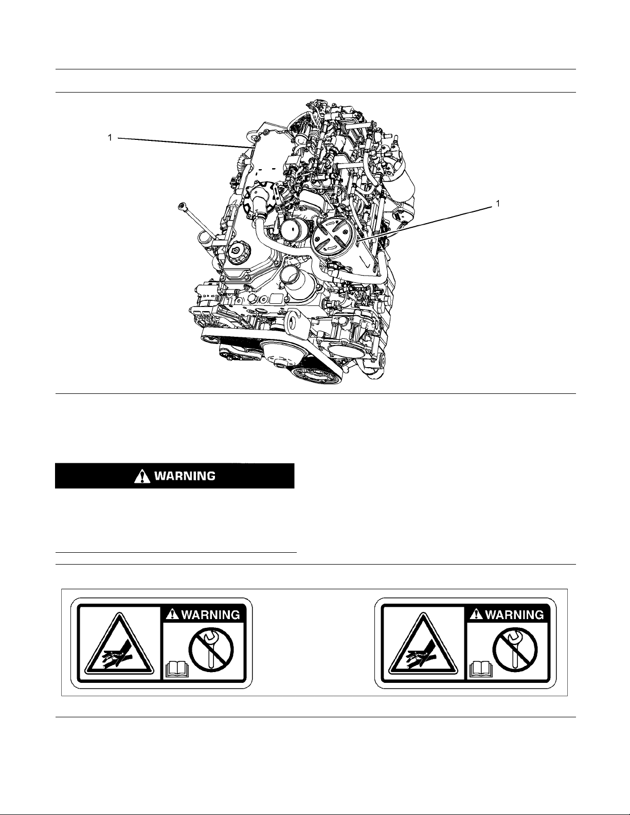
The Universal W
positions. The warning labels are located on the rear
right side of the valve mechanism cover and located
on the top for t
arning label (1) is located in two
he NOx reduction system (NRS).
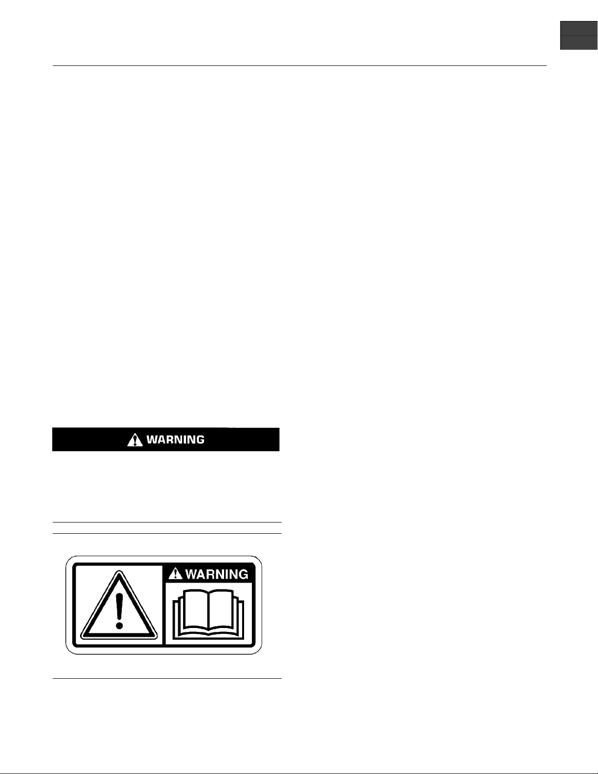
(1) Universal Warning
Do not operate or work on this equipment unless
ave read and understand the instructions
you h
and warnings in the Operation and Maintenance
Manuals. Failure to follow the instructions or
the warnings could result in serious injury
heed
or death.
Illustration 1
ypical example
T
g01154807
Page 6
6 SEBU8605-01
Safety Section
Safety Messages
Illustration 2
ersal Warning
(1) Univ
(2) Han
d (High Pressure)
Contact with high pressure fuel may cause fluid
penetration and burn hazards. High pressure fu-
ay may cause a fire hazard. Failure to fol-
el spr
low these inspection, maintenance and service instructions may cause personal injury or death.
g02406137
Illustration 3
Typical example
2382677
g0
Page 7
SEBU8605-01 7
Safety Section
General Hazard Information
Illustration 4
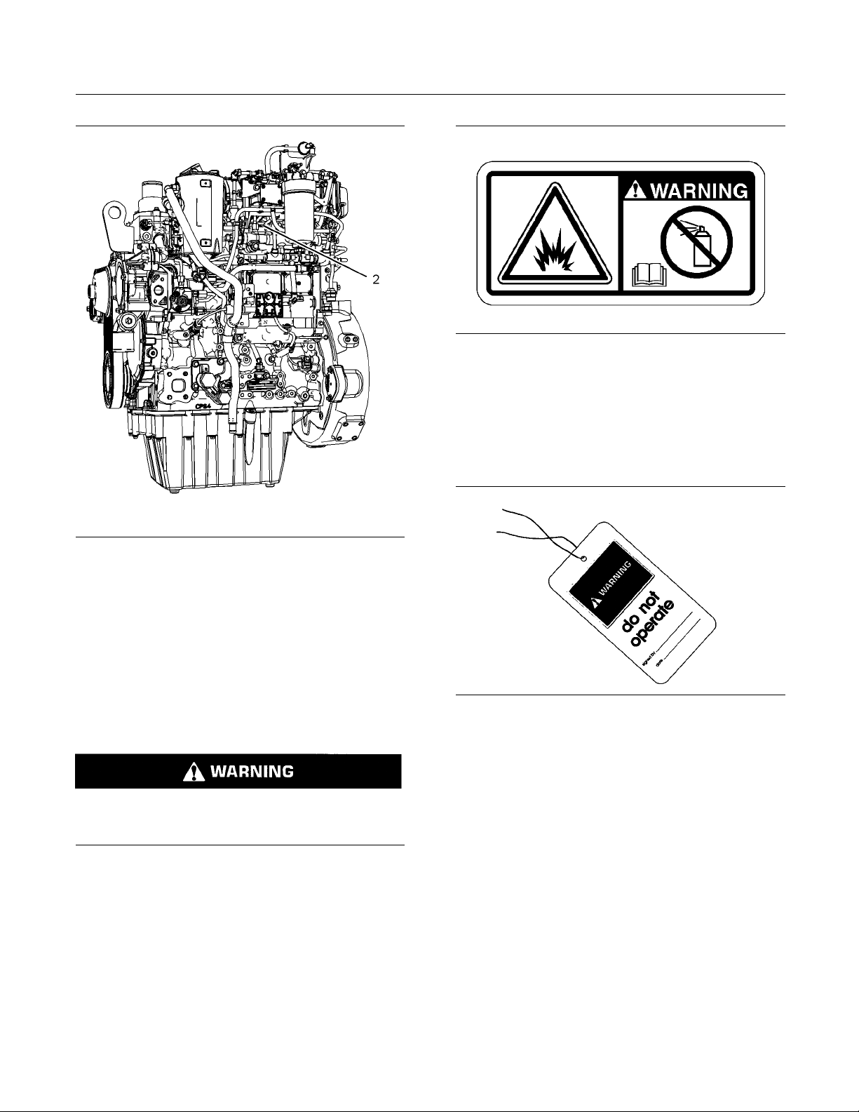
(2) Hand
(High Pressure )
g02406178
The warning label for the Hand (High Pressure)
(2) is a
wrap around label that is installed on the
high-pressure fuel line.
Ether Warning
her warning label will be installed on the air
The et
cleaner or close to the air cleaner. The location will
depend on the application.
Do not use aerosol types of starting aids suc h as
ether. Such use could result in an explosion and
personal injury.
Illustration 5
Typical exa mple
g01154809
i03566024
General Hazard Inf ormation
Illustration 6
Attach a “Do Not Operate” warning tag or a similar
warning tag to the start switch or to the controls
before the engine is serviced or before the engine is
repaired. Attach the warning tags to the engine and to
each operator control station. When it is appropriate,
disconnect the starting controls.
Do not allow unauthorized personnel on the engine,
or around the engine when the engine is being
serviced.
g00104545
Tampering with the engine installation or tampering
•
with the OEM supplied wiring can be dangerous.
Personal injury, death and/or engine damage could
result.
Vent the engine exhaust to the outside when the
•
engine is operated in an enclosed area.
Page 8
8 SEBU8605-01
Safety Section
General Hazard Information
If the engine is
•
secondary brake or the parking brake systems
unless the vehicle is blocked or unless the vehicle
is restrained
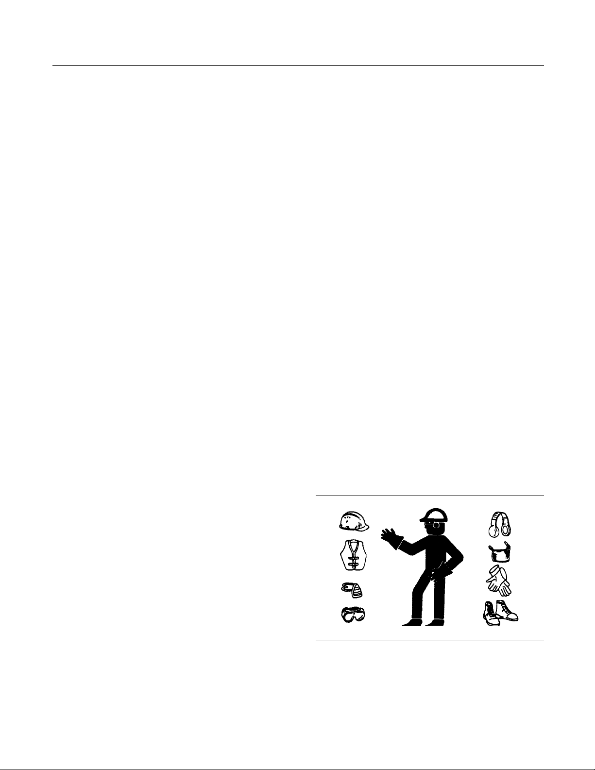
Wear a hard hat, protective glasses, and other
•
protective e
When work is performed around an engine that is
•
operating,
to help prevent damage to hearing.
Do not wear l
•
on controls or on other parts of the engine.
Ensure tha
•
securedinplaceontheengine.
Never put m
•
Glass containers can break.
Use all cl
•
Report all necessary repairs.
•
Unless other instructions are provided, perform the
maintenance under the following conditions:
not running, do not release the
.
quipment, as required.
wear protective devices for ears in order
oose clothing or jewelry that can snag
t all protective guards and all covers are
aintenance fluids into glass containers.
eaning solutions with care.
For initial sta
•
engine that has been serviced, make provisions to
stop the engine if an overspeed occurs. This may
be accomplish
and/or the air supply to the engine.
Start the eng
•
Never short across the starting motor terminals or
the batteries. This could bypass the engine neutral
start syste
damaged.
Engine exha
which may be harmful to your health. Always start the
engine and operate the engine in a well ventilated
area. If th
engine exhaust to the outside.
Cautiousl
prevent spraying or splashing of pressurized fluids,
hold a rag over the part that is being removed.
Filler caps
•
Grease fit
•
Pressure taps
•
rt-up of a new engine or for starting an
ed by shutting off the fuel supply
ine from the operator's station (cab).
m and/or the electrical system could be
ust contains products of combustion
e engine is in an enclosed area, vent the
y remove the following parts. To help
tings
The engine is stopped. Ensure that the engine can
•
not be started.
Theprotectivelocksorthecontrolsareinthe
•
applied position.
Engage the secondary brakes or parking brakes.
•
the vehicle or restrain the vehicle before
Block
•
maintenance or repairs are performed.
nnect the batteries when maintenance
Disco
•
is performed or when the electrical system is
serviced. Disconnect the battery ground leads.
the leads in order to help prevent sparks.
Ta p e
Disconnect the connector for the unit injector that
•
cated on the valve cover base. This will help
is lo
prevent personal injury from the high voltage to the
unit injectors. Do not come in contact with the unit
ector terminals while the engine is operating.
inj
Do not attempt any repairs or any adjustments to
•
engine while the engine is operating.
the
Do not attempt any repairs that are not understood.
•
e the proper tools. Replace any equipment that
Us
is damaged or repair the equipment.
Breathers
•
Drain pl
•
Use caution when cover plates are removed.
Gradua
bolts or nuts that are located at opposite ends of
the cover plate or the device. Before removing the
last t
relieve any spring pressure or other pressure.
Illustration 7
Wear a hard hat, protective glasses, and other
•
protective equipment, as required.
ugs
lly loosen, but do not remove the last two
wo bolts or nuts, pry the cover loose in order to
g00702020
When work is performed around an engine that is
•
operating, wear protective devices for ears in order
to help prevent damage to hearing.
Page 9
SEBU8605-01 9
Safety Section
General Hazard Information
Do not wear loos
•
on controls or on other parts of the engine.
Ensure that al
•
securedinplaceontheengine.
Never put mai
•
Glass containers can break.
Use all clea
•
Report all necessary repairs.
•
Unless other instructions are provided, perform
the maintenance under the following conditions:
The engine is stopped. Ensure that the engine
•
cannot be started.
Disconnect the batteries when maintenance
•
is performed or when the electrical system is
serviced
Tape the leads in order to help prevent sparks.
Do not att
•
Use the proper tools. Replace any equipment that
is damaged or repair the equipment.
. Disconnect the battery ground leads.
empt any repairs that are not understood.
e clothing or jewelry that can snag
l protective guards and all covers are
ntenance fluids into glass containers.
ning solutions with care.
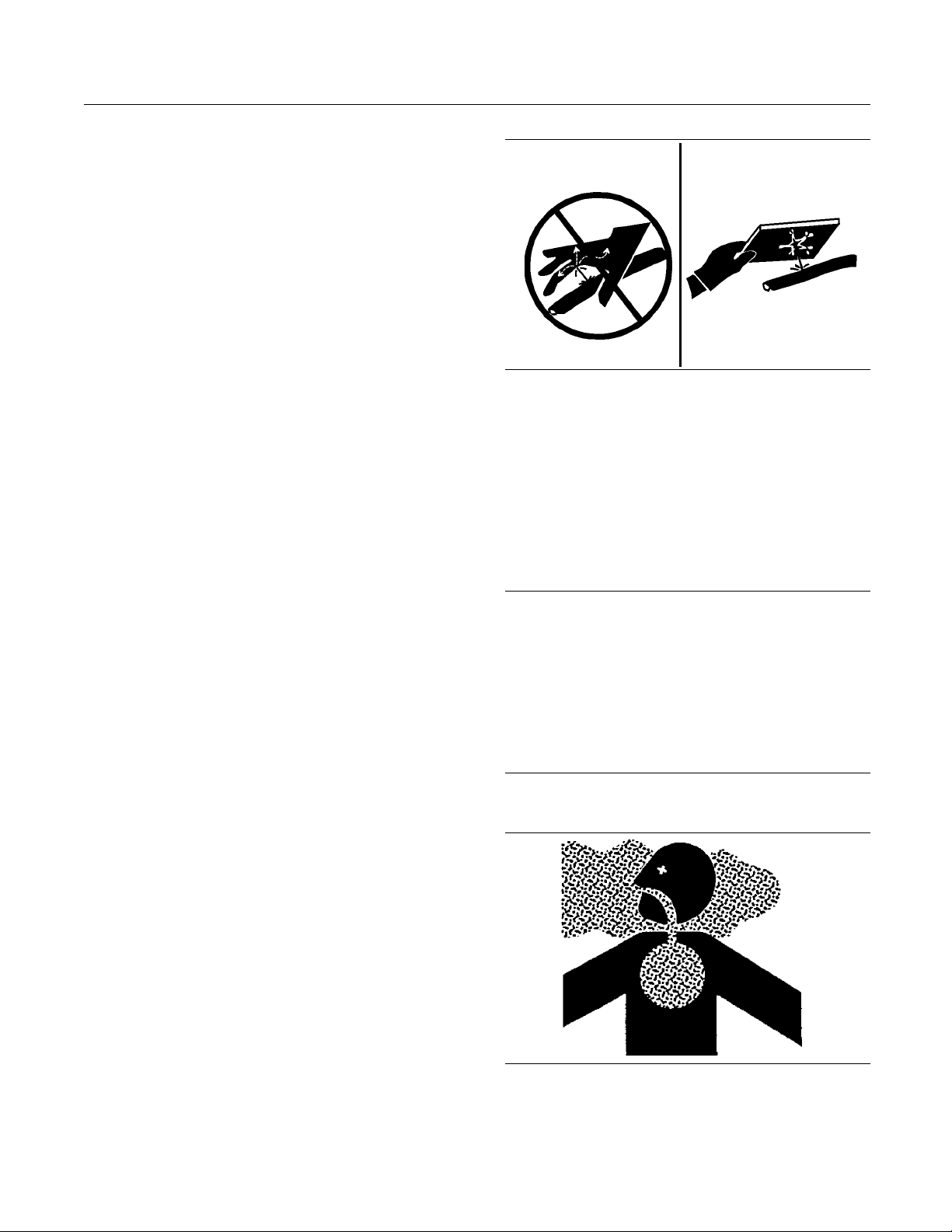
Illustration 8
Always use a board or cardboard when you check
for a leak. Leaking fluid that is under pressure can
penetrate body tissue. Fluid penetration can cause
serious injury and possible death. A pin hole leak can
cause severe injury. If fluid is injected into your skin,
you must get treatment immediately. Seek treatment
from a doctor that is familiar with this type of injury.
g00687600
Containing Fluid Spillage
Pressurized Air and Water
Pressurized air and/or water can cause debris
and/or hot water to be blown out. This could result in
person
When pressurized air and/or pressurized water is
used f
shoes, and eye protection. Eye protection includes
goggles or a protective face shield.
The maximum air pressure for cleaning purposes
must be below 205 kPa (30 psi). The maximum
wate
275kPa(40psi).
al injury.
or cleaning, wear protective clothing, protective
r pressure for cleaning purposes must be below
Fluid Penetration
sure can be trapped in the hydraulic circuit long
Pres
after the engine has been stopped. The pressure can
cause hydraulic fluid or items such as pipe plugs to
ape rapidly if the pressure is not relieved correctly.
esc
Do not remove any hydraulic components or parts
il pressure has been relieved or personal injury
unt
may occur. Do not disassemble any hydraulic
components or parts until pressure has been relieved
personal injury may occur. Refer to the OEM
or
information for any procedures that are required to
relieve the hydraulic pressure.
NOTICE
Care must be taken to ensure that fluids are contained
during performance of inspection, maintenance, testing, adjustingand repair of the product. Be prepared to
collect the fluid with suitable containers before opening any compartment or disassembling any component containing fluids.
Dispose of all fluids according to local regulations and
mandates.
Asbestos Information
Illustration 9
g00702022
Page 10
10 SEBU8605-01
Safety Section
Burn Prevention
Perkins replac
Perkins are asbestos free. Perkins recommends
the use of only genuine Perkins replacement parts.
Use the follow
replacement parts that contain asbestos or when you
handle asbestos debris.
Use caution. Avoid inhaling dust that might be
generated when you handle components that contain
asbestos fib
to your health. The components that may contain
asbestos fibers are brake pads, brake bands, lining
material, c
asbestos that is used in these components is usually
boundinaresinorsealedinsomeway.Normal
handling i
contains asbestos is generated.
If dust tha
are several guidelines that should be followed:
Never use
•
Avoid brushing materials that contain asbestos.
•
Avoid grinding materials that contain asbestos.
•
ement parts that are shipped from
ing guidelines when you handle any
ers. Inhaling this dust can be hazardous
lutch plates, and some gaskets. The
s not hazardous unless airborne dust that
t may contain asbestos is present, there
compressed air for cleaning.
Dispose of Waste Properly
Illustration 10
Improperly disposing of waste can threaten the
environment. Potentially harmful fluids should be
dispose
Always use leakproof containers when you drain
fluids. D
drain, or into any source of water.
d of according to local regulations.
o not pour waste onto the ground, down a
g0070640
4
Use a wet
•
materials.
A vacuum
•
efficiency particulate air filter (HEPA) can also be
used.
Use exhaust ventilation on permanent machining
•
jobs.
Wear an approved respirator if there is no other
•
way to control the dust.
Comply with applicable rules and regulations
•
for the work place. In the United States, use
Occu
(OSHA) requirements. These OSHA requirements
can be found in “29 CFR 1910.1001”.
Obey environmental regulations for the disposal
•
of asbestos.
Stay away from areas that might have asbestos
•
particles in the air.
method in order to clean up asbestos
cleaner that is equipped with a high
pational Safety and Health Administration
i04224009
Burn Prevention
Do not touch any part of an operating engine
system. The engine, the exhaust, and the engine
aftertreatment system surface temperatures can
reach temperatures of approximately 600° C
(1112 ° F) under normal operating conditions.
Allow the engine system to cool before any
maintenance is performed.
Relieve all pressure in the following systems,
hydraulic system, lubrication system, fuel system,
and the coolant system before the related items are
disconnected.
Contact with high pressure fuel may cause fluid
penetration and burn hazards. High pressure fuel spray may cause a fire hazard. Failure to follow these inspection, maintenance and service instructions may c ause personal injury or death.
After the engine has stopped, you must wait for 10
minutes in order to allow the fuel pressure to be
purged from the high-pressure fuel lines before any
service or repair is performed on the engine fuel lines.
Page 11
SEBU8605-01 11
Safety Section
Fire Prevention and Explosion Prevention
Allow the press
the hydraulic system, in the lubrication system, or
in the cooling system before any lines, fittings, or
related items
Induction Sys
Sulfuric Acid Burn Hazard may cause serious personal injury or death.
The exhaust gas cooler may contain a small
amount of sulfuric acid. The use of fuel with sulfur levels
amount of sulfuric acid formed. The sulfuric acid
may spill from the cooler during service of the
engine. Th
and clothing on contact. Always wear the appropriate personal protective equipment (PPE) that
is noted o
for sulfuric acid. Always follow the directions for
first aid that are noted on a material safety data
sheet (M
ure to be purged in the air system, in
are disconnected.
tem
greater than 15 ppm may increase the
e sulfuric acid will burn the eyes, skin
n a material safety data sheet (MSDS)
SDS) for sulfuric acid.
Batteries
Electrolyte i
injury. Do not allow electrolyte to contact the skin or
the eyes. Always wear protective glasses for servicing
batteries. Wa
and connectors. Use of gloves is recommended.
s an acid. Electrolyte can cause personal
sh hands after touching the batteries
i03652933
Fire Prevention and Explosion
Prevention
Coolant
When the engine is at operating temperature, the
engine
pressure. The radiator and all lines to the heaters or
to the engine contain hot coolant.
Any contact with hot coolant or with steam can cause
severe burns. Allow cooling system components to
cool b
Check that the coolant level after the engine has
stop
Ensure that the filler cap is cool before removing the
fille
withabarehand.Removethefiller cap slowly in
order to relieve pressure.
Cooling system conditioner contains alkali. Alkali can
cause personal injury. Do not allow alkali to contact
the
Oil
Hot oil and hot lubricating components can cause
pe
skin. Also, do not allow hot components to contact
the skin.
coolant is hot. The coolant is also under
efore the cooling system is drained.
ped and the engine has been allowed to cool.
rcap.Thefiller cap must be cool enough to touch
skin, the eyes, or the mouth.
s
rsonal injury. Do not allow hot oil to contact the
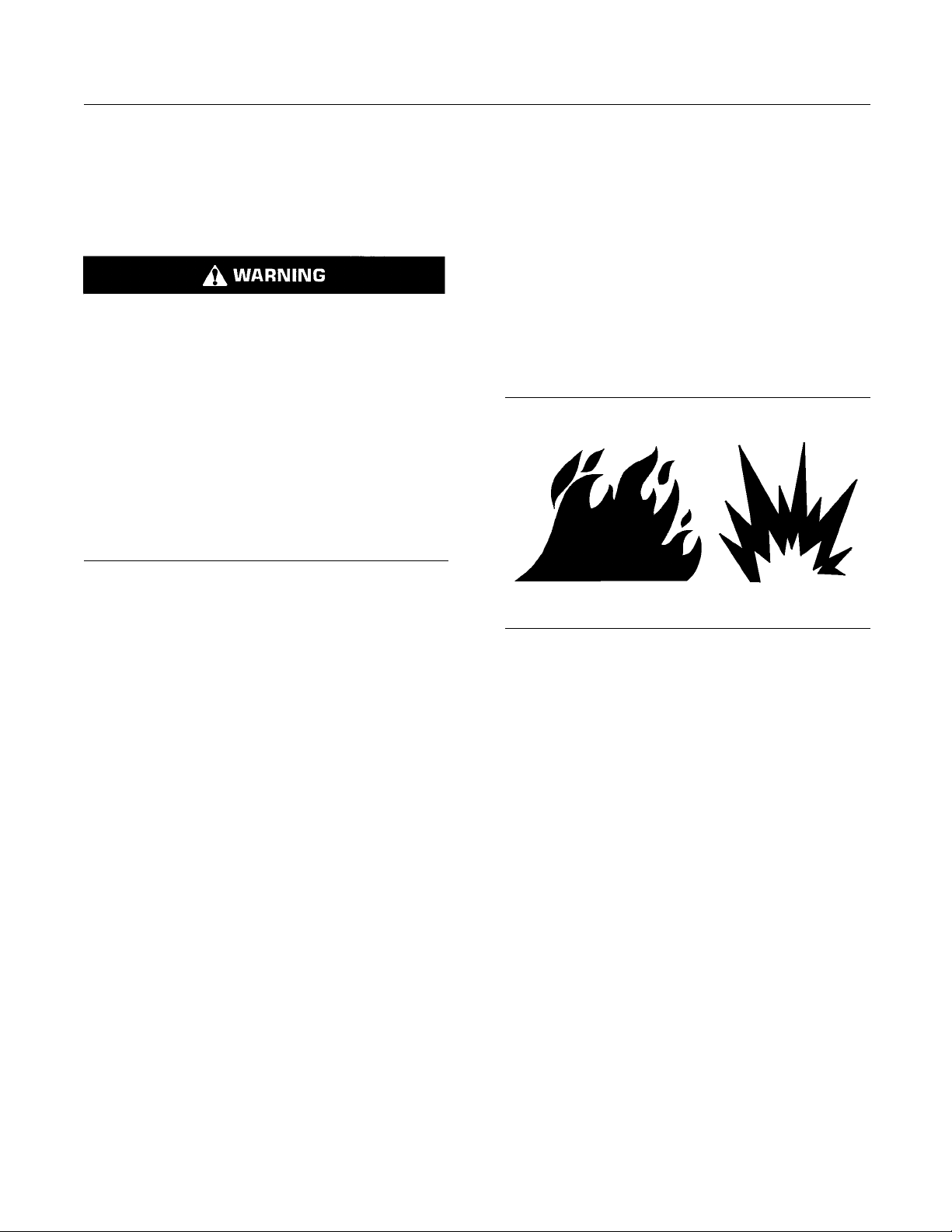
Illustration 11
All fuels, most lubricants, and some coolant mixtures
are flammable.
Flammable fluids that are leaking or spilled onto hot
surfaces or onto electrical components can cause
a fire. Fire may cause personal injury and property
damage.
After the emergency stop button is operated ensure
that you allow 15 minutes, before the engine covers
are removed.
Determinewhethertheenginewillbeoperatedinan
environment that allows combustible gases to be
drawn into the air inlet system. These gases could
cause the engine to overspeed. Personal injury,
property damage, or engine damage could result.
If the application involves the presence of combustible
gases, consult your Perkins dealer and/or your
Perkins distributor for additional information about
suitable protection devices.
Remove all flammable combustible materials or
conductive materials such as fuel, oil, and debris from
the engine. Do not allow any flammable combustible
materials or conductive materials to accumulate on
the engine.
g00704000
Page 12
12 SEBU8605-01
Safety Section
Fire Prevention and Explosion Prevention
Store fuels and
lubricants in correctly marked
containers away from unauthorized persons. Store
oily rags and any flammable materials in protective
containers. D
o not smoke in areas that are used for
storing flammable materials.
Do not expose
theenginetoanyflame.
Exhaust shields (if equipped) protect hot exhaust
components
from oil or fuel spray in case of a line,
a tube, or a seal failure. Exhaust shields must be
installed correctly.
Do not weld on lines or tanks that contain flammable
fluids. Do not flame cut lines or tanks that contain
flammable fl
uid. Clean any such lines or tanks
thoroughly with a nonflammable solvent prior to
welding or flame cutting.
Wiring must be kept in good condition. All electrical
wires must be correctly routed and securely attached.
Check all
electrical wires daily. Repair any wires
that are loose or frayed before you operate the
engine. Clean all electrical connections and tighten
all elect
rical connections.
Eliminate all wiring that is unattached or unnecessary.
Do not us
e any wires or cables that are smaller than
the recommended gauge. Do not bypass any fuses
and/or circuit breakers.
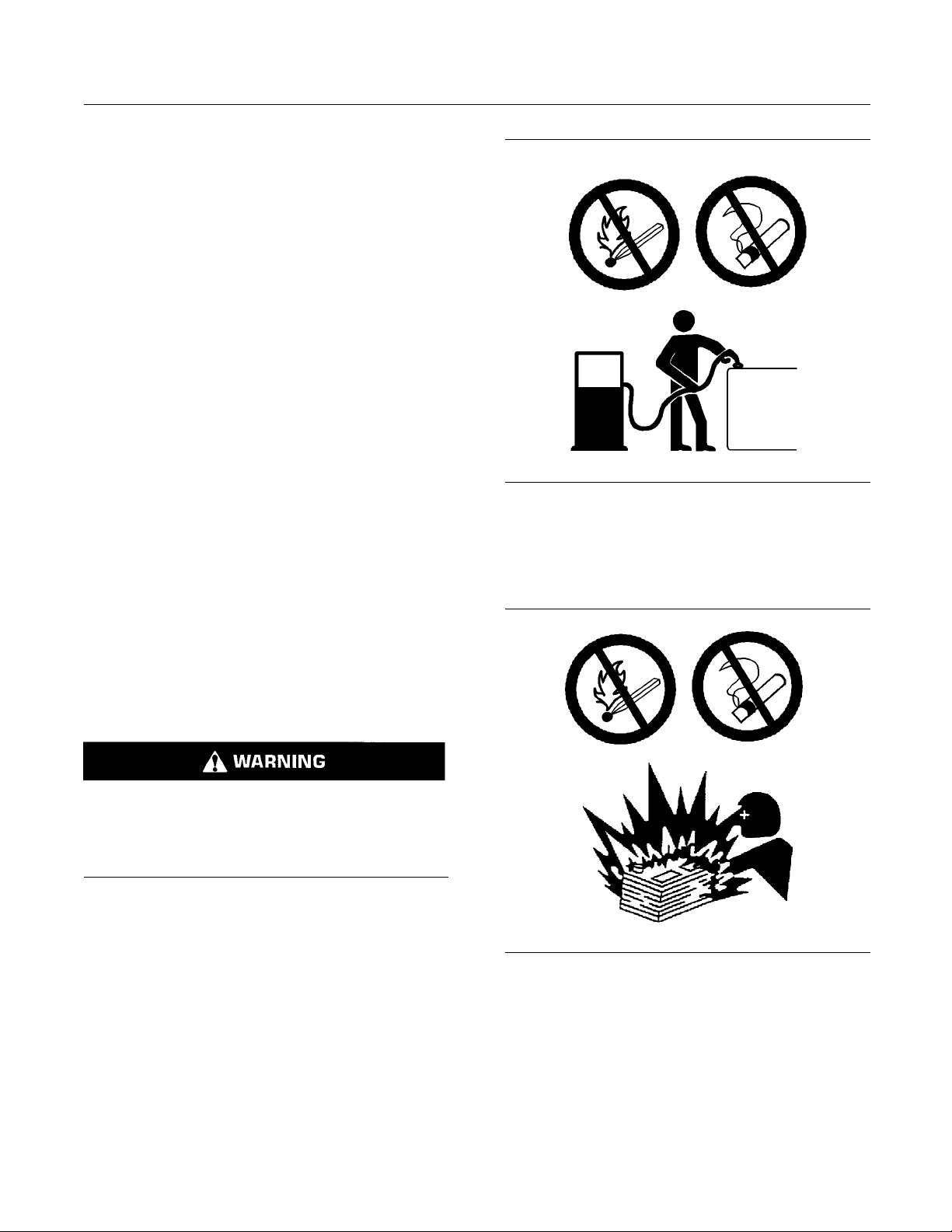
Illustration 12
g00704059
Use caution when you are refueling an engine. Do
not smoke while you are refueling an engine. Do not
refuel an engine near open flames or sparks. Always
stop the engine before refueling.
Arcing or sparking could cause a fire. Secure
connections, recommended wiring, and correctly
ined battery cables will help to prevent arcing
mainta
or sparking.
Contact with high pressure fuel may cause fluid
tration and burn hazards. High pressure fu-
pene
el spray may cause a fire hazard. Failure to follow these inspection, maintenance and service in-
ctions may cause personal injury or death.
stru
After the engine has stopped, you must wait for 10
utes in order to allow the fuel pressure to be
min
purged from the high pressure fuel lines before any
service or repair is performed on the engine fuel lines.
Ensure that the engine is stopped. Inspect all lines
and hoses for wear or for deterioration. The hoses
st be correctly routed. The lines and hoses must
mu
have adequate support and secure clamps.
l filters and fuel filters must be correctly installed.
Oi
The filter housings must be tightened to the correct
torque. Refer to the Disassembly and Assembly
anual for more information.
m
Illustration 13
g00704135
Gases from a battery can explode. Keep any open
flames or sparks away from the top of a battery. Do
not smoke in battery charging areas.
Never check the battery charge by placing a metal
object across the terminal posts. Use a voltmeter or
ahydrometer.
Page 13

SEBU8605-01 13
Safety Section
Crushing Prevention and Cutting Prevention
Incorrect jump
an explosion that can result in injury. Refer to
the Operation Section of this manual for specific
instructions
Do not charge a frozen battery. This may cause an
explosion.
The batteries must be kept clean. The covers
(if equippe
recommended cables, connections, and battery box
covers when the engine is operated.
er cable connections can cause
.
d) must be kept on the cells. Use the
Fire Extinguisher
Make sure that a fire extinguisher is available. Be
familiar with the operation of the fire extinguisher.
Inspect th
extinguisher regularly. Obey the recommendations
on the instruction plate.
e fire extinguisher and service the fire
Lines, Tubes and Hoses
Do not bend high pressure lines. Do not strike high
pressure lines. Do not install any lines that are
damaged
Leaks can cause fires. Consult your Perkins dealer
or your P
Replace the parts if any of the following conditions
are pre
.
erkins distributor for replacement parts.
sent:
i02143194
Crushing Prevention and
Cutting Preve
Support the component correctly when work beneath
the component is performed.
Unless other maintenance instructions are provided,
never attempt adjustments while the engine is
running.
Stay clear of all rotating parts and of all moving
parts. Lea
is performed. After the maintenance is performed,
reinstall the guards.
Keep objects away from moving fan blades. The fan
blades will throw objects or cut objects.
When objects are struck, wear protective glasses in
order to avoid injury to the eyes.
Chips or other debris may fly off objects when objects
are struck. Before objects are struck, ensure that no
one will
ve the guards in place until maintenance
be injured by flying debris.
ntion
i04016709
Mounting and Dismounting
High pressure fuel line or lines are removed.
•
End fittings are damaged or leaking.
•
coverings are chafed or cut.
Outer
•
Wires are exposed.
•
Outer coverings are ballooning.
•
ible part of the hoses are kinked.
Flex
•
Outer covers have embedded armoring.
•
End fittings are displaced.
•
e sure that all clamps, guards, and heat shields
Mak
are installed correctly. During engine operation, this
will help to prevent vibration, rubbing against other
ts, and excessive heat.
par
Do not climb on the engine or the engine
aftertreatment. The engine and aftertreatment have
not been designed with mounting or dismounting
locations.
Refer to the OEM for the location of foot and hand
holds for your specific application.
i03814031
h Pressure Fu el Lines
Hig
Contact with high pressure fuel may cause fluid
enetration and burn hazards. High pressure fu-
p
el spray may cause a fire hazard. Failure to follow these inspection, maintenance and service in-
tructions may c ause personal injury or death.
s
Page 14
14 SEBU8605-01
Safety Section
High Pressure Fuel Lines
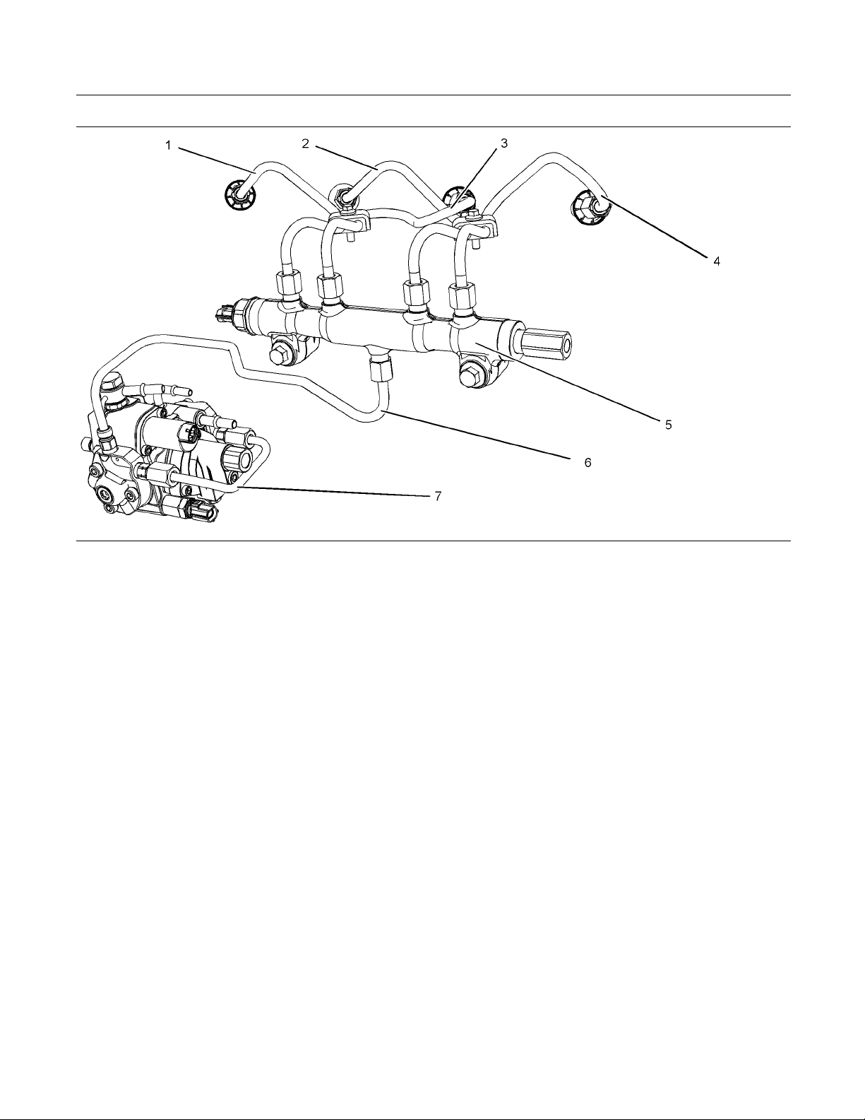
Illustration 14
(1) High
(2) High
(3) Hig
-pressure line
-pressure line
h-pressure line
-pressure line
(4) High
-pressure fuel manifold (rail)
(5) High
h-pressure line
(6) Hig
The high-pressure fuel lines are the fuel lines that
are bet
ween the high-pressure fuel pump and the
high-pressure fuel manifold and the fuel lines that are
between the fuel manifold and cylinder head. These
ines are different from fuel lines on other fuel
fuel l
systems.
These
•
•
•
differences are because of the following items:
The high-pressure fuel lines are constantly charged
high pressure.
with
The internal pressures of the high-pressure fuel
s are higher than other types of fuel system.
line
The high-pressure fuel lines are formed to shape
then strengthened by a special process.
and
Do not step on the high-pressure fuel lines. Do not
ect the high-pressure fuel lines. Do not bend or
defl
strike the high-pressure fuel lines. Deformation or
damage of the high-pressure fuel lines may cause a
int of weakness and potential failure.
po
Do not check the high-pressure fuel lines with the
gine or the starting motor in operation. After the
en
engine has stopped wait 10 minutes in order to allow
the fuel pressure to be purged from the high-pressure
uel lines. before any service or repair is performed.
f
g02067853
transfer line that is high pressure
(7) Fuel
Do not loosen the high-pressure fuel lines in order
to remo
ve air from the fuel system. This procedure
is not required.
lly inspect the high-pressure fuel lines before
Visua
the engine is started. This inspection should be each
day.
If you inspect the engine in operation, always use
the proper inspection procedure in order to avoid
d penetration hazard. Refer to Operation and
a flui
Maintenance Manual, “General hazard Information”.
ect the high-pressure fuel lines for damage,
Insp
•
deformation, a nick, a cut, a crease, or a dent.
ot operate the engine with a fuel leak. If there
Do n
•
is a leak, do not tighten the connection in order
to stop the leak. The connection must only be
htened to the recommended torque. Refer to
tig
Disassembly and Assembly, “Fuel injection lines Remove and Fuel injection lines - Install”.
If the high-pressure fuel lines are torqued correctly,
•
and the high-pressure fuel lines are leaking the
gh-pressure fuel lines must be replaced.
hi
Page 15

SEBU8605-01 15
Safety Section
Before Starting Engine
Ensure that all
•
are in place. Do not operate the engine with clips
that are damaged, missing, or loose.
Do not attach any other item to the high-pressure
•
fuel lines.
Loosened high-pressure fuel lines must be
•
replaced. Also removed high-pressure fuel lines
must be repl
Assembly manual, “ Fuel Injection Lines - Install”.
clips on the high-pressure fuel lines
aced. Refer to Disassembly and
i02813489
Before Starting Engine
Before the initial start-up of an engine that is new,
serviced or repaired, make provision to shut the
engine off, in order to stop an overspeed. This may
be accomplished by shutting off the air and/or fuel
supply to the engine.
Overspeed shutdown should occur automatically for
engines that are controlled electronically. If automatic
shutdown does not occur, press the emergency stop
button in order to cut the fuel and/or air to the engine.
Inspect the engine for potential hazards.
Before starting the engine, ensure that no one is on,
underneath, or close to the engine. Ensure that the
area is free of personnel.
If equipped, ensure that the lighting system for the
engine is suitable for the conditions. Ensure that all
lights work correctly, if equipped.
All protective guards and all protective covers must
be installed if the engine must be started in order
to perform service procedures. To help prevent an
accident that is caused by parts in rotation, work
around the parts carefully.
Do not bypass the automatic shutoff circuits. Do not
disable the automatic shutoff circuits. The circuits are
provided in order to help prevent personal injury. The
circuits are also provided in order to help prevent
engine damage.
See the Service Manual for repairs and for
adjustments.
i03996487
Engine Starting
Do not use aerosol types of starting aids such as
ether. Such use could result in an explosion and
personal in
If a warning tag is attached to the engine start switch,
or to the co
the controls. Consult with the person that attached
the warning tag before the engine is started.
All protective guards and all protective covers must
be installed if the engine must be started in order
to perfor
accident that is caused by parts in rotation, work
around the parts carefully.
Start the engine from the operators compartment or
from the engine start switch.
Always start the engine according to the procedure
that is described in the Operation and Maintenance
Manual
Section. Knowing that the correct procedure will help
to prevent major damage to the engine components.
Knowin
personal injury.
To ens
and/or the lube oil heater (if equipped) is working
correctly, check the water temperature gauge. Also,
check
operation.
ne exhaust contains products of combustion
Engi
which can be harmful to your health. Always start the
engine and operate the engine in a well ventilated
. If the engine is started in an enclosed area,
area
vent the engine exhaust to the outside.
e: The engine is equipped with a device for cold
Not
starting. If the engine will be operated in very cold
conditions, then an extra cold starting aid may be
uired. Normally, the engine will be equipped with
req
the correct type of starting aid for your region of
operation.
These engines are equipped with a glow plug starting
aid in each individual cylinder that heats the intake air
order to improve starting. Some Perkins engines
in
may have a cold starting system that is controlled by
the ECM that allows a controlled flow of ether into
he engine. The ECM will disconnect the glow plugs
t
before the ether is introduced. This system would
be installed at the factory.
jury.
ntrols DO NOT start the engine or move
m service procedures. To help prevent an
, “Engine Starting” topic in the Operation
g that the procedure will also help to prevent
ure that the jacket water heater (if equipped)
the oil temperature gauge during the heater
Page 16
16 SEBU8605-01
Safety Section
Engine Stopping
i02234873
Engine Stopping
Stop the engin
the Operation and Maintenance Manual, “Engine
Stopping (Operation Section)” in order to avoid
overheating
the engine components.
Use the Emer
in an emergency situation. Do not use the Emergency
Stop Button for normal engine stopping. After an
emergency
problem that caused the emergency stop has been
corrected.
Stop the engine if an overspeed condition occurs
during the initial start-up of a new engine or an engine
that has b
To stop an electronically controlled engine, cut the
power to t
to the engine.
e according to the procedure in
of the engine and accelerated wear of
gency Stop Button (if equipped) ONLY
stop, DO NOT start the engine until the
een overhauled.
he engine and/or shutting off the air supply
i04231629
Grounding Practices
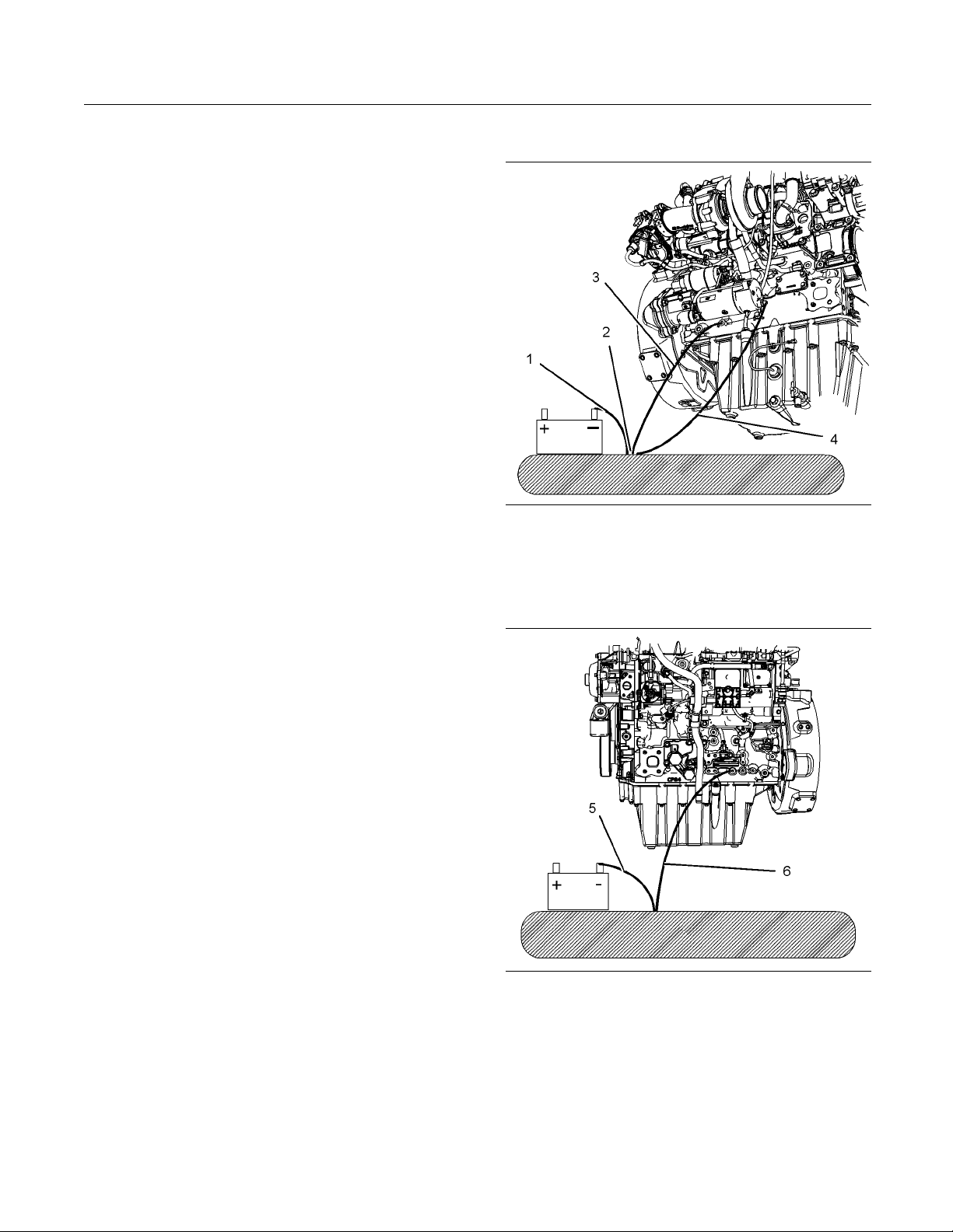
Illustration 15
Typical exa mple
(1) Ground to the battery
(2) Primary position for grounding
(3) Ground to the starting motor
(4) Ground to the engine block
g02407417
Electrical System
Never disconnect any charging unit circuit or battery
circuit cable from the battery when the charging unit
is operating. A spark can cause the combustible
gases that are produced by some batteries to ignite.
To help prevent sparks from igniting combustible
gases that are produced by some batteries, the
negative “−” cable should be connected last from
the external power source to the primary position for
grounding.
Check the electrical wires daily for wires that
are loose or frayed. Tighten all loose electrical
connections before the engine is started. Repair all
frayed electrical wires before the engine is started.
See the Operation and Maintenance Manual for
specific starting instructions.
Illustration 16
Typical exa mple
(5) Ground to the battery
(6) Ground to the cylinder block
g02407418
Correct grounding for the engine electrical system
is necessary for optimum engine performance
and reliability. Incorrect grounding will result in
uncontrolled electrical circuit paths and in unreliable
electrical circuit paths.
Page 17
SEBU8605-01 17
Safety Section
Engine Electronics
Uncontrolled e
damage to the crankshaft bearing journal surfaces
and to aluminum components.
Engines that are installed without engine-to-frame
ground straps can be damaged by electrical
discharge.
To ensure that the engine and the engine electrical
systems fun
ground strap with a direct path to the battery must be
used. This path may be provided by way of a direct
engine grou
The connections for the grounds should be tight and
free of cor
grounded to the negative “-” battery terminal with
a wire that is adequate to handle the full charging
current of
The power supply connections and the ground
connecti
be from the isolator to the battery.
lectrical circuit paths can result in
ction correctly, an engine-to-frame
nd to the frame.
rosion. The engine alternator must be
the alternator.
ons for the engine electronics should always
i03642610
Engine Electronics
Derate
•
Shutdown
•
The following monitored engine operating conditions
have the ability to limit engine speed and/or the
engine power
Engine Coolant Temperature
•
Engine Oil Pressure
•
Engine Spee
•
Intake Manifold Air Temperature
•
Engine Intake Throttle Valve Fault
•
Wastegate
•
Supply Voltage to Sensors
•
Fuel Pressure in Manifold (Rail)
•
NOx Reduc
•
Engine Aftertreatment System
•
:
d
Regulator
tion System
Tampe
or the OEM wiring installation can be dangerous
and could result in personal injury o r death and/or
engin
Electrical Shock Hazard. The electronic unit injectors use DC voltage. The ECM s ends this voltage
to the electronic unit injectors. Do not come in
contact with the harness connector for the electronic unit injectors while the engine is operating.
Failure to follow this instruction could result in
personal injury or death.
This engine has a comprehensive, programmable
Engine Monitoring System. The Electronic Control
Module (ECM) has the ability to monitor the engine
operating conditions. If any of the engine parameters
extend outside an allowable range, the ECM will
initiate an immediate action.
ring with the electronic system installation
e damage.
The Engine Monitoring package can vary for different
engine models and different engine applications.
However
monitoring control will be similar for all engines.
Note: M
modules that are available for Perkins Engines will
work in unison with the Engine Monitoring System.
Toget
monitoring function for the specific engine application.
Refer to Troubleshooting for more information on the
Engin
, the monitoring system and the engine
any of the engine control systems and display
her, the two controls will provide the engine
eMonitoringSystem.
The following actions are available for engine
monitoring control:
Warning
•
Page 18
18 SEBU8605-01
Product Information Section
Model Views
Product Information
Section
Model Views
i04231649
Model View Illustrations
The following model views show typical features
of the engine and the aftertreatment system.
Due to individual applications, your engine, or
your aftertreatment may appear different from the
illustrations.
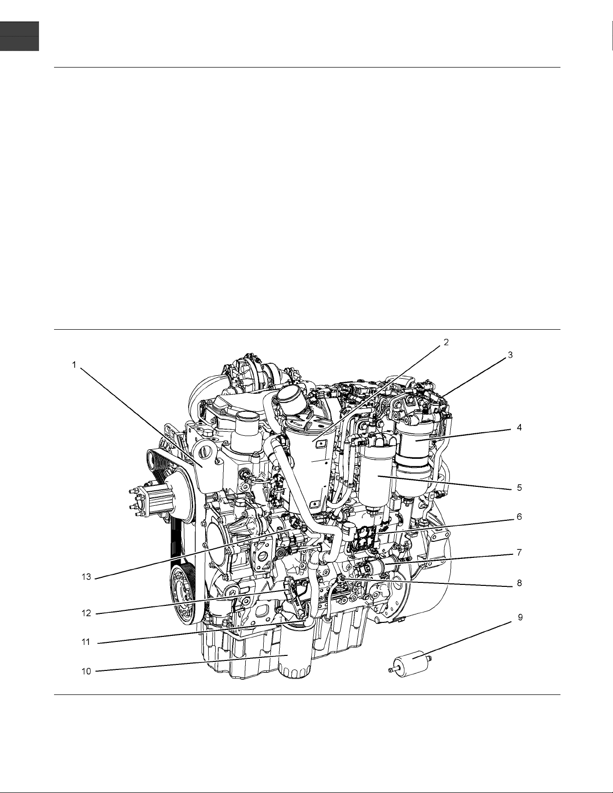
1204E-E44TTA
Illustration 17
(1) Front lifting eye
(2) Crankcase breather
(3) N Ox Reduction system (NRS)
(4) Primary fuel filter
(5) Secondary fuel filter
(6) Electronic control module (ECM)
(7) Fuel priming pump
(8) Oil gauge (dipstick)
(9) Fuel strainer
(10) Oil filter
g02409511
(11) Oil sampling valve
(12) Oil filler
(13) High-pressure fuel pump
Page 19
SEBU8605-01 19
Product Information Section
Model Views
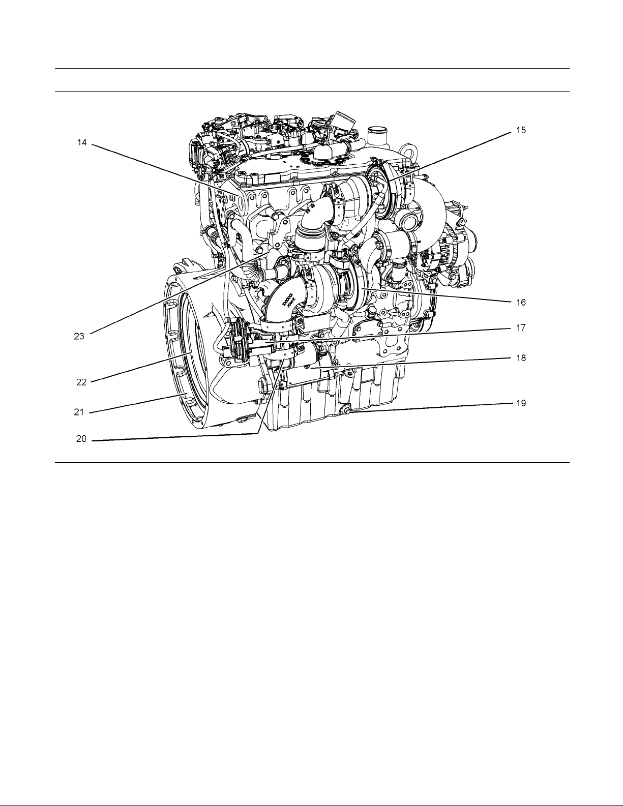
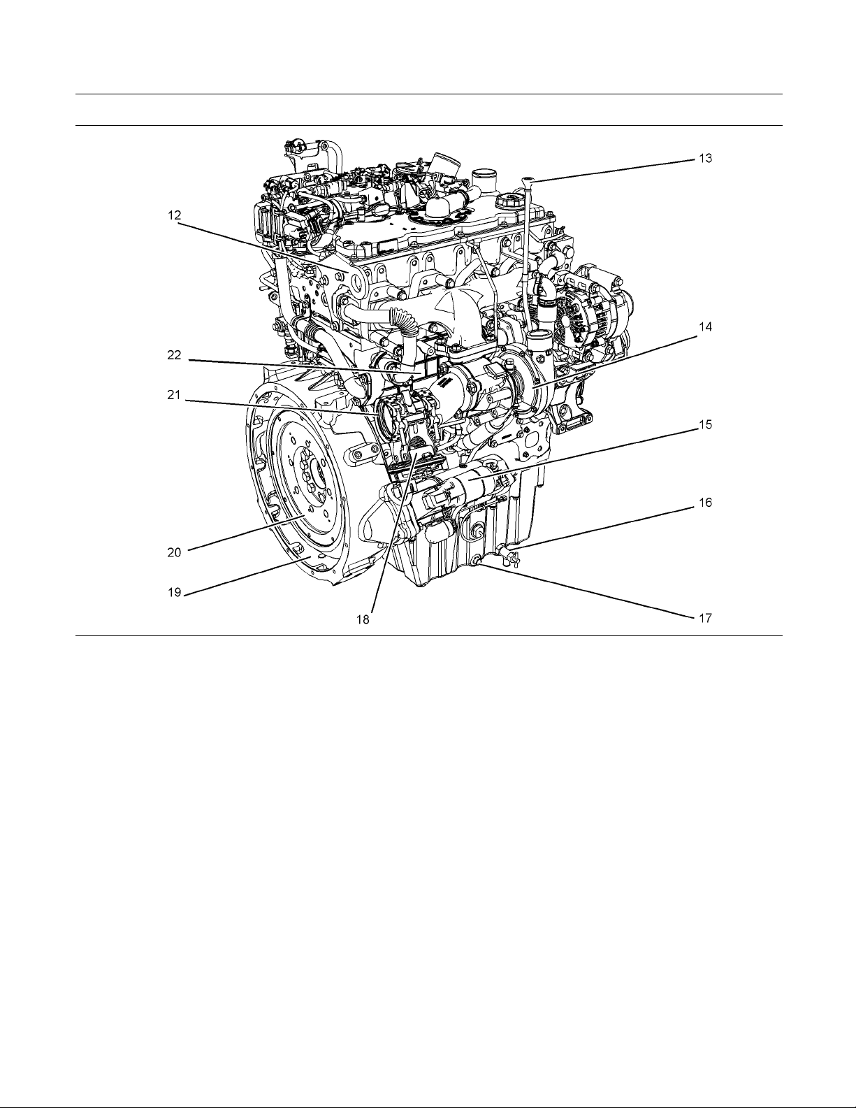
Illustration 18
(14) Rear lifting eye
(15) High-pressure turbocharger
(16) Low-pressure turbocharger
(17) Back pressure valve
(18) Starting motor
(19) Oil drain plug
(20) Exhaust outlet
(21) Flywheel housing
g02409512
(22) Flywheel
(23) NRS cooler
Page 20
20 SEBU8605-01
Product Information Section
Model Views
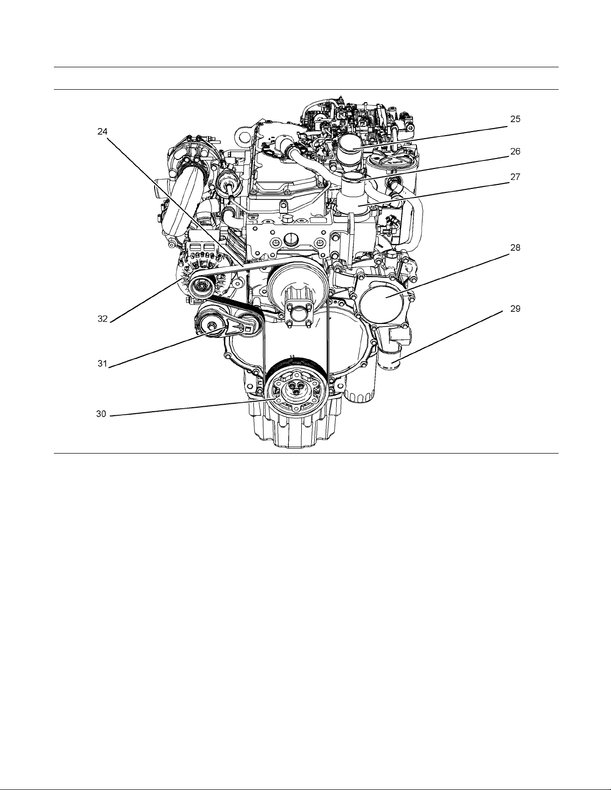
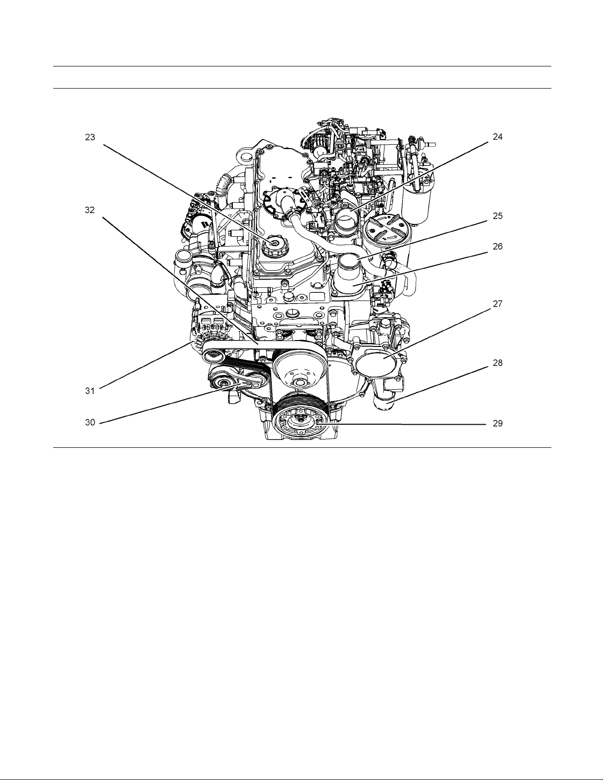
Illustration 19
(24) Belt
(25) Air intake
(26) Coolant outlet connection
(27) Thermostat housing
(28) Water pum p
(29) Coolant inlet connection
g02409862
(30) Crankshaft pulley
(31) Belt tensioner
(32) Alternator
Page 21
SEBU8605-01 21
Product Information Section
Model Views
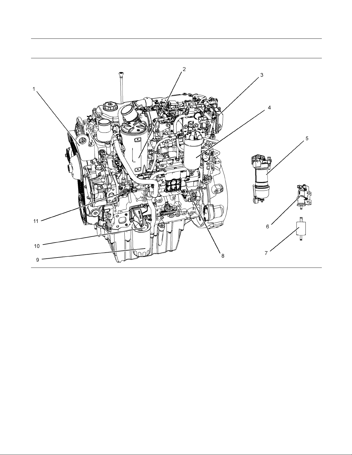
1204E-E44TA
Illustration 20
(1) Front lifting eye
(2) Crankcase breather
(3) NOx reduction system (NRS)
(4) Secondary fuel filter
(5) Primary f u el filter
(6) Fuel priming pump
(7) Fuel strainer
(8) Electronic control module (ECM)
g02407436
(9) Oil fi lter
(10) Oil sampling valve
(11) High-pressure fuel pump
Page 22
22 SEBU8605-01
Product Information Section
Model Views
Illustration 21
(12) Rear lifting eye
(13) Oil gauge (dipstick)
(14) Turbocharger
(15) Starting motor
(16) Oil drain valve
(17) Oil drain plug
(18) Back pressure valve
(19) Flywheel housing
g02407536
(20) Flywheel
(21) Exhaust outlet
(22) NRS cooler
Page 23
SEBU8605-01 23
Product Information Section
Model Views
Illustration 22
(23) Oil filler
(24) Air intake
(25) Outlet connection for coolant
(26) Thermostat housing
(27) Water pum p
(28) Coolant intake connector
(29) Rear lifting eye
(30) Belt tensioner
g02407537
(31) Alternator
(32) Belt
Page 24
24 SEBU8605-01
Product Information Section
Model Views
Engine Aftertreatment System
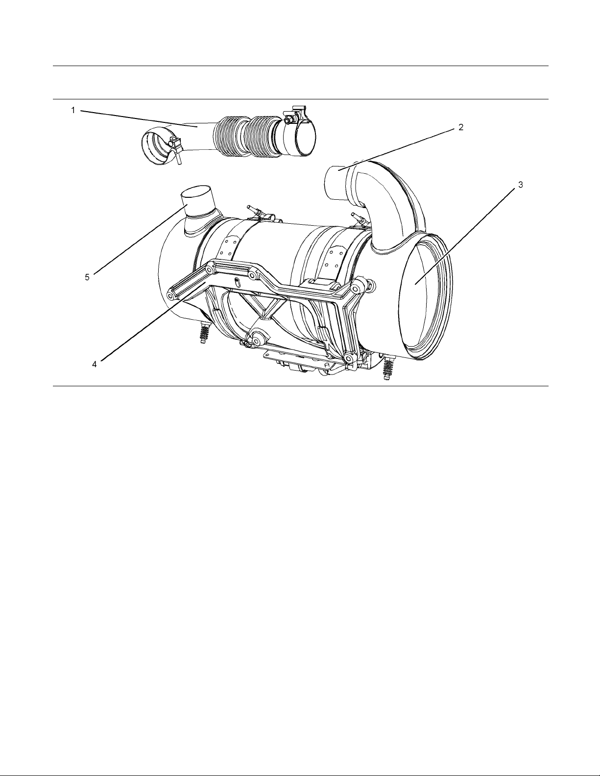
Illustration 23
Typical example
xible exhaust pipe
(1) Fle
et connection
(2) Inl
Engin
e Description
an emissions module
(3) Cle
nting cradle
(4) Mou
i04340692
Perkins has designed two versions of the 1204E
industrial engine.
1204E-E44TA (MK)
•
4E-E44TTA (ML)
120
•
The 1204E-E44TA (MK) engine is equipped with a
gle turbocharger.
sin
The 1204E-E44TTA (ML) engine is equipped with
ries turbochargers. An engine that is equipped
se
with series turbochargers have a low-pressure
turbocharger and a high-pressure turbocharger.
g02483
let connec tion
(5) Out
Turbocharged charge cooled
•
Engine Specifications
The front end of the engine is opposite the flywheel
end of the engine. The left and the right sides of the
ne are determined from the flywheel end. The
engi
number 1 cylinder is the front cylinder.
616
The Perkins 1204E industrial engines have the
following characteristics.
In-line four cylinder
•
our stroke cycle
F
•
Page 25
SEBU8605-01 25
Product Information Section
Model Views
Electronic Engine Features
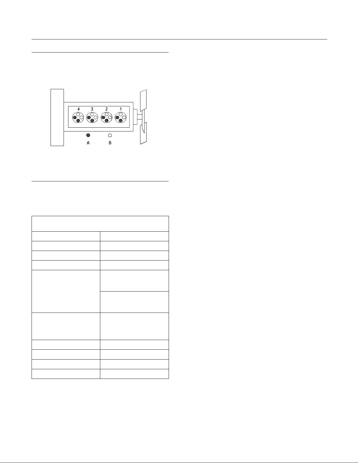
Illustration 24
(A) Exhaust valves
(B) Inlet valves
Table 1
1204E-E44TA and 1204E-E44TTA Engine
Operating Range (rpm) 800 to 2200
Number of Cylinders 4 In-Line
Bore
Stroke 127 mm (4.99 inch)
Power
Aspiration
Compression Ratio
Displacement
Firing Order 1-3-4-2
Rotation (flywheel end) Counterclockwise
(1)
The operating rpm is dependent on the engine rating, the
application, and the configuration of the throttle.
Specifications
105 mm (
(80.46 to 147.51 hp)
(140.805 to 173.65 hp)
MK Single Turbocharged
charge cooled
ML Series Turbocharged
charge cooled
4.4 L (268.504 cubic inch)
4.13 inch)
MK
60 to 110 kW
ML
105 to129.5 kW
16.5:1
g01187485
(1)
Theengineope
rating conditions are monitored.
The Electronic Control Module (ECM) controls the
response of the engine to these conditions and to
the demands of
the operator. These conditions and
operator demands determine the precise control of
fuel injection by the ECM. The electronic engine
control syst
Engine monitoring
•
Engine speed governing
•
Control of t
•
Cold start strategy
•
Automatic air/fuel ratio control
•
Torque ri
•
Injection timing control
•
System diagnostics
•
Aftertr
•
em provides the following features:
he injection pressure
se shaping
eatment low temperature regeneration
For more information on electronic engine features,
refer to
the Operation and Maintenance Manual,
“Features and Controls” topic (Operation Section).
Engine Diagn ostics
The eng
that the engine systems are functioning correctly. The
operator will be alerted to the condition by a “Stop or
Warni
horsepower and the vehicle speed may be limited.
Theelectronicservicetoolmaybeusedtodisplay
the di
There are three types of diagnostic codes: active,
logg
Most of the diagnostic codes are logged and stored
in th
the Operation and Maintenance Manual, “Engine
Diagnostics” topic (Operation Section).
The ECM provides an electronic governor that
controls the injector output in order to maintain the
des
ine has built-in diagnostics in order to ensure
ng” lamp. Under certain conditions, the engine
agnostic codes.
ed, and event.
e ECM. For additional information, refer to
ired engine rpm.
gine Cooling and Lubrication
En
The cooling system and lubrication system consists
the following components:
of
Gear-driven centrifugal water pump
•
Page 26

26 SEBU8605-01
Product Information Section
Model Views
Water temperat
•
engine coolant temperature
Gear-driven r
•
Oil cooler
•
The engine lubricating oil is supplied by a rotor type
oil pump. The engine lubricating oil is cooled and the
engine lubr
can provide unrestricted flow of lubrication oil to
the engine if the oil filter element should become
plugged.
Engine efficiency, efficiency of emission controls, and
engine per
operation and maintenance recommendations.
Engine performance and efficiency also depend on
the use of r
coolants. Refer to this Operation and Maintenance
Manual, “Maintenance Interval Schedule” for more
informat
formance depend on adherence to proper
ion on maintenance items.
Aftertre
The aftertreatment system is approved for use by
Perkins
approved Perkins aftertreatment system must be
used on a Perkins engine.
. In order to be emission-compliant only the
ure regulator which regulates the
otor type oil pump
icating oil is filtered. The bypass valve
ecommended fuels, lubrication oils, and
atment System
Expected engin
average power that is demanded. The average power
that is demanded is based on fuel consumption of the
engine over a p
at full throttle and/or operating at reduced throttle
settings result in a lower average power demand.
Reduced hour
operating time before an engine overhaul is required.
e life is generally predicted by the
eriod. Reduced hours of operation
s of operation will increase the length of
Aftermarket Products and Perkins
Engines
Perkins does not warrant the quality or performance
of non-Perk
When auxiliary devices, accessories, or consumables
(filters, a
manufacturers are used on Perkins products, the
Perkins warranty is not affected simply because of
such use.
However, failures that result from the installation
or use of o
accessories, or consumables are NOT Perkins
defects. Therefore, the defects are NOT covered
under th
ins fluids and filters.
dditives, catalysts,) which are made by other
ther manufacturers devices,
e Perkins warranty.
Clean Emission Mo dule (CEM)
The CEM
single unit, the Diesel Oxidation Catalyst DOC and
the Diesel Particulate Filter DPF. The function of the
CEM is
the required emissions regulation for the country of
operation.
Theengineexhaustisconnectedbyaflexible pipe to
the CEM. The exhaust gases pass through the DOC
in or
and hydrocarbons. The exhaust gases then enter the
DPF where any particulate matter soot and ash will
be tr
The CEM uses a passive regeneration process to
ure that normal operation of the engine removes
ens
the soot. The soot is removed at an equal rate of
which the soot is captured. The ash remains in the
DPF
En
Engine efficiency and maximum utilization of engine
rformance depend on the adherence to proper
pe
operation and maintenance recommendations. In
addition, use recommended fuels, coolants, and
bricants. Use the Operation and Maintenance
lu
Manual as a guide for required engine maintenance.
comprises of two main components in a
to ensure that the engine exhaust meets
der to remove contaminants, carbon monoxide,
apped.
and must be removed at an engine overhaul.
gine Service Life
Page 27
SEBU8605-01 27
Product Information Section
Product Identification Information
Product Identification
Information
i03865704
Plate Locations and Film
Locations
(Engine Aftertreatment System
)
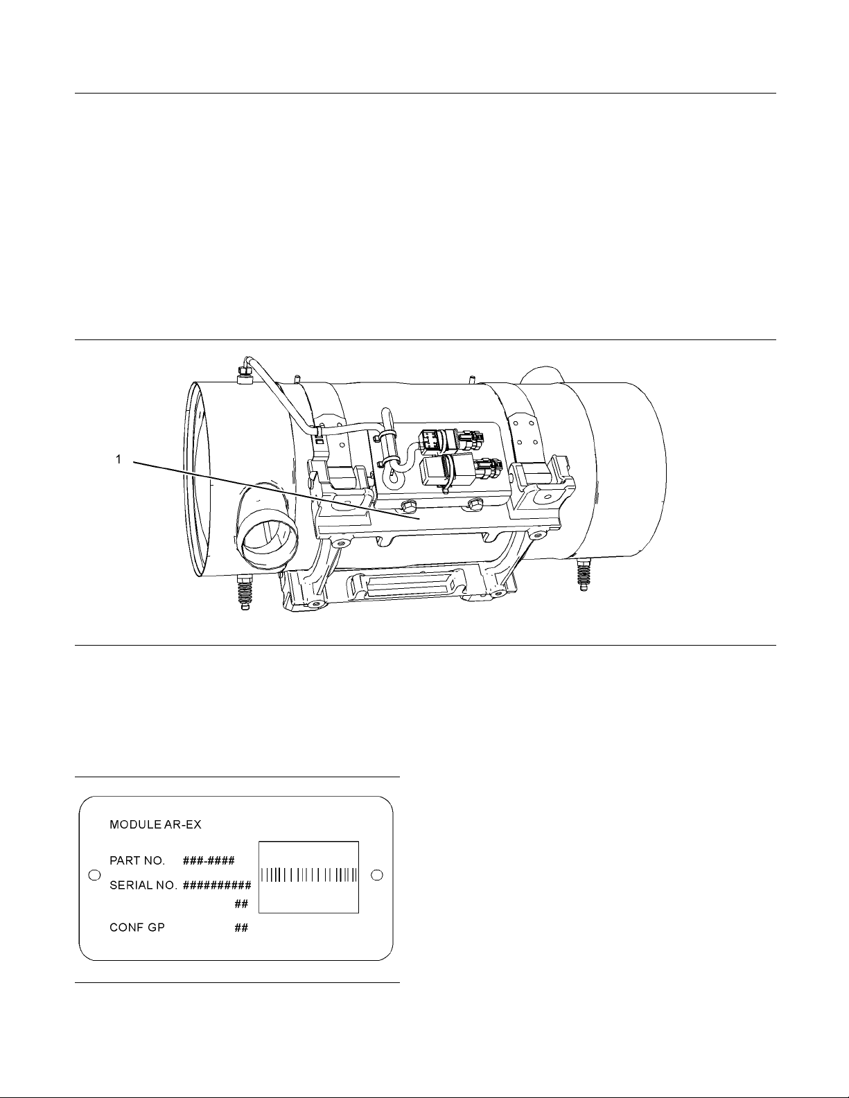
Illustration 25
Typical example
The module arrangement exhaust plate is installed
on the mounting plate (1). The location of the
arrangement plate mounting plate can alter
depending on the application.
Illustration 26
Module Arrangement Exhaust Plate
g02109493
g02109488
Record the information that is on the plate. This
information identifies the engine aftertreatment
system. This information will be required by your
Perkins distributor. The information is essential in
order to be emissions complaint.
Page 28
28 SEBU8605-01
Product Information Section
Product Identification Information
Plate Locations and Film
Locations
(Engine)
i03827189
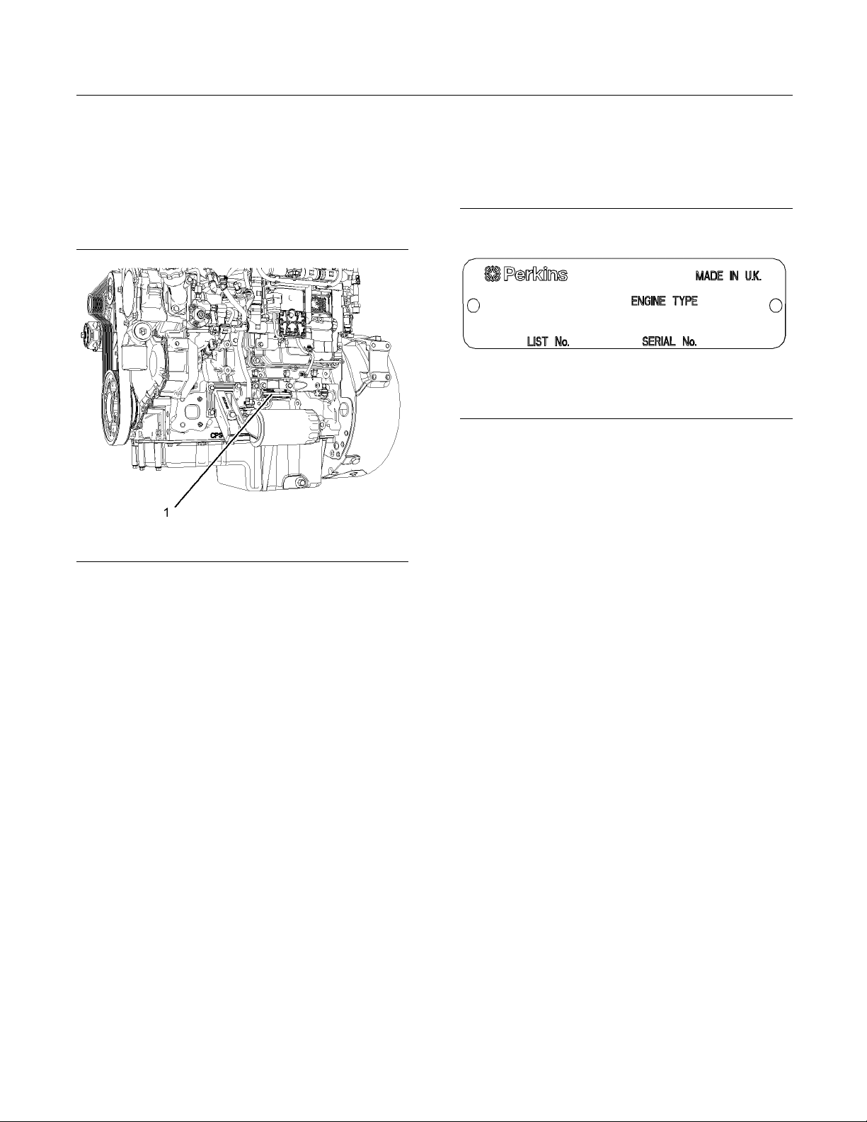
Serial Number Plate (1)
Theengineserialnumberplateislocatedonthe
left side of the cylinder block to the rear of the front
engine mounting.
ation 28
Illustr
Serial number plate
g02101733
i038672
Reference Num bers
76
Illustration 27
g02077373
Perkins engines are identified by an engine serial
number.
An example of an engine number is
ML*****U000001U.
*****
____________________The list number for the engine
_____________________________________The type of engine
ML
____________________________ Built in the United Kingdom
U
000001
U
___________________________ Engine Serial Number
_____________________________________Year of Manufacture
Perkins dealers or Perkins distributors need all of
these numbers in order to determine the components
that were included with the engine. This information
permits accurate identification of replacement part
numbers.
The numbers for fuel setting information for electronic
engines are stored within the flash file. These
numbers can be read by using the electronic service
tool.
ation for the following items may be needed to
Inform
order parts. Locate the information for your engine.
Record the information in the appropriate space.
Make a
copy of this list for a record. Keep the
information for future reference.
Record for Reference
ne Model
Engi
Engine Serial number _____________________________________
Engine Low Idle rpm ______________________________________
ine Full Load rpm
Eng
Primary Fuel Filter _________________________________________
Water Separator Element ________________________________
condary Fuel Filter Element
Se
Lubrication Oil Filter Element ___________________________
Auxiliary Oil Filter Element _______________________________
otal Lubrication System Capacity
T
_______________________________________________
_____________________________________
__________________________
_____________________
Total Cooling System Capacity _______ __________________
Air Cleaner Element _______________________________________
Page 29
SEBU8605-01 29
Product Information Section
Product Identification Information
Drive Belt ____
________________________________________________
Engine Aftertreatment System
Part Number ________________________________________________
______________________________________________
Serial Numbe
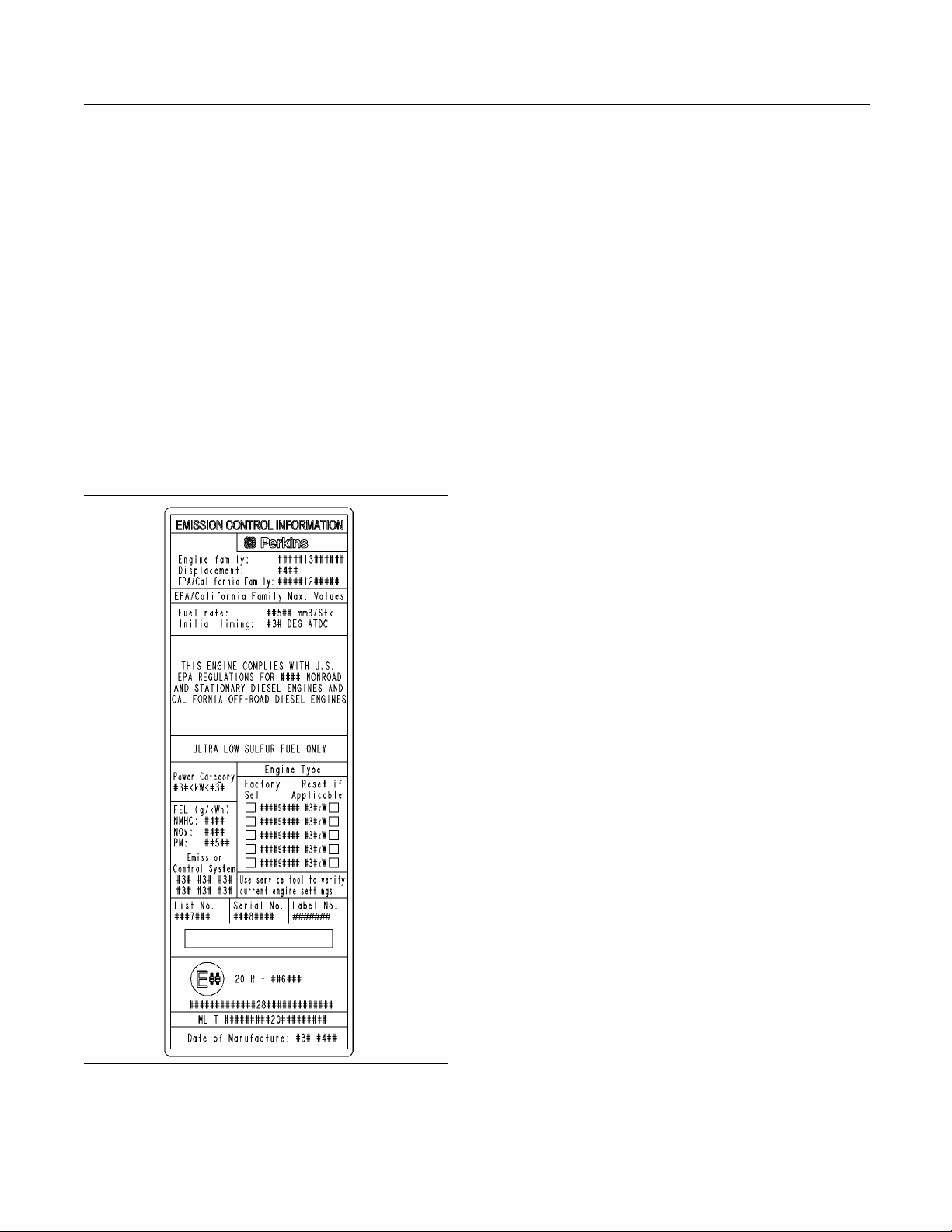
Emissions C
An emission label is installed on the front gear cover.
Note: Asec
the engine. If necessary, the second emission label
will be installed on the application by the original
equipment
r
i04274850
ertification Film
ondemissionlabelwillbesuppliedwith
manufacturer.
Illustration 29
Typical example
g02443596
Page 30
30 SEBU8605-01
Operation Section
Lifting and Storage
Operation Section
Lifting and Storage
Product Lifting
(Engine)
i04332972
Some removals r
obtain correct balance and safety.
To re mov e th e e
are on the engine.
Lifting eyes
engine arrangements. Alterations to the lifting eyes
and/or the engine make the lifting eyes and the lifting
fixtures obs
that correct lifting devices are provided. Consult
your Perkins dealer or your Perkins distributor for
informatio
lifting.
n regarding fixtures for correct engine
equire lifting the fixtures in order to
ngine ONLY, use the lifting eyes that
are designed and installed for specific
olete. If alterations are made, ensure
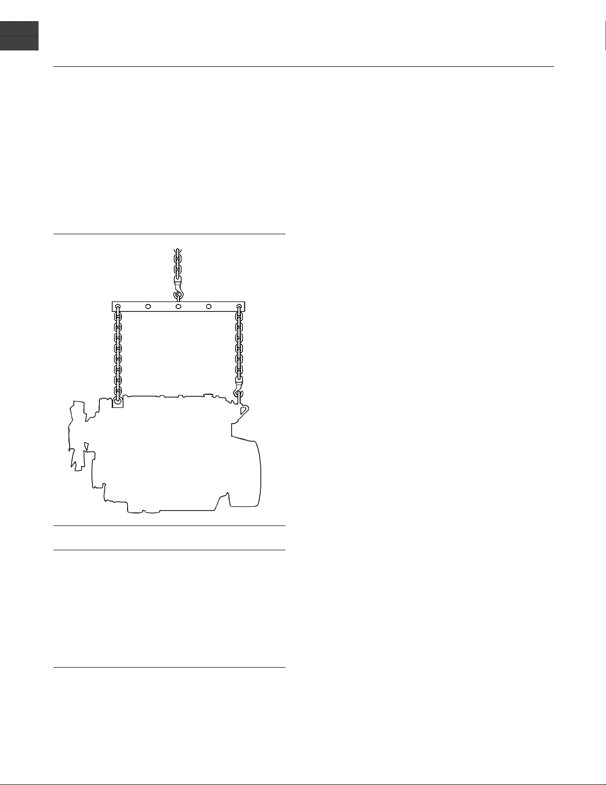
Illustration 30
NOTICE
er bend the eyebolts and the brackets. Only load
Nev
the eyebolts and the brackets under tension. Remember that the capacity of an eyebolt is less as the angle
ween the supporting members and the object be-
bet
comes less than 90 degrees.
en it is necessary to remove a component at an
Wh
angle, only use a link bracket that is properly rated for
the weight.
Use a hoist to remove heavy components. Use
an adjustable lifting beam to lift the engine. All
upporting members (chains and cables) should be
s
parallel to each other. The chains and cables should
be perpendicular to the top of the object that is being
lifted.
g01097527
Page 31

SEBU8605-01 31
Operation Section
Lifting and Storage
Industrial Open Power Unit
Illustration 31
Typical example
ation of f ront lifting eye
(1) Loc
ation of rear lifting eye
(2) Loc
g02488
437
Page 32

32 SEBU8605-01
Operation Section
Lifting and Storage
Product Lifting
(Clean Emissi
on Module)
i04195469
i04084189
Product Storag e
(Engine and Af
Perkins are not responsible for damage which may
occur when an engine is in storage after a period in
service.
Your Perkins dealer or your Perkins distributor can
assist in pr
periods.
Condition for Storage
The engine
The building must be kept at a constant temperature.
Engines that are filled with Perkins ELC will have
coolant p
−36° C (−32.8° F). The engine must not be subjected
to extreme variations in temperature and humidity.
Storage Period
eparing the engine for extended storage
must be stored in a water proof building.
rotectiontoanambienttemperatureof
tertreatment)
Illustration 32
Ensure that the correct clothing is worn, refer to
this Operation and Maintenance Manual, “General
Hazard Information”.
The weight of the clean emission module (CEM)
when laden is approximately 50 kg (110 lb). Two
suitable double looped slings are required in order to
lift the CEM. Also a suitable hoist will be required in
order to remove and install the assembly.
The slings must be attached to the CEM in the
positions as shown in illustration 32.
Ensure that the slings only contact the body of the
CEM. A test lift may be required in order to achieve
the correct balance of the assembly.
Some applications may require a frame or jig in order
to lift the CEM. A frame or jig must only be connected
to the cradle of the CEM. Refer to the OEM for more
information.
g02385036
An engin
all the recommendation are adhered to.
Storag
Keep a record of the procedure that has been
comple
Note: Do not store an engine that has biodiesel in
the fu
1. Ensure that the engine is clean and dry.
2. Dra
e can be stored for up to 6 months provided
e Procedure
ted on the engine.
el system.
a. If the engine has been operated using biodiesel,
thesystemmustbedrainedandnewfilters
alled. The fuel tank will require flushing.
inst
b. Fill the fuel system with an ultra low sulfur fuel.
ore information on acceptable fuels refer
For m
to this Operation and Maintenance Manual,
“Fluid recommendations”. Operate the engine
15 minutes in order to remove all biodiesel
for
from the system.
in any water from the primary filter water
separator. Ensure that the fuel tank is full.
e engine oil will not need to be drained in
3. Th
order to store the engine. Provided the correct
specification of engine oil is used the engine
n be stored for up to 6 months. For the
ca
correct specification of engine oil refer to this
Operation and Maintenance Manual, “Fluid
ecommendations”.
r
Page 33

SEBU8605-01 33
Operation Section
Lifting and Storage
4. Remove the driv
Sealed Coolant System
Ensure that the cooling system is filled with Perkins
ELC, or an antifreeze that meets “ASTM D6210”
specificatio
Open C ooling System
Ensure that all cooling drain plugs have been
opened. Allow the coolant to drain. Install the drain
plugs. Plac
The coolant system must be sealed once the vapor
phase inhibitor has been introduced. The effect of the
vapor phas
is open to the atmosphere.
For mainte
and Maintenance Manual.
Aftertre
No special procedures are required. The exhaust
outlet o
storing, the engine and the aftertreatment must be
enclosed in a cover.
n.
e a vapor phase inhibitor into the system.
e inhibitor will be lost if the cooling system
nance procedures ref to this Operation
atment
f the aftertreatment should be capped. Before
e belt from the engine.
Monthly Checks
The cra
the spring loading on the valve train. Rotate
the crankshaft more than 180 degrees. Visibly
check f
aftertreatment.
Ensur
covered completely before storage. Log the
procedure in the record for the engine.
nkshaft must be rotated in order to change
or damage or corrosion to the engine and
e that the engine and aftertreatment are
Page 34

34 SEBU8605-01
Operation Section
Gauges and Indicators
Gauges and Ind icators
i04220531
Gauges and Indicators
Your engine
the gauges that are described. For more information
about the gauge package, see the OEM information.
Gauges provide indications of engine performance.
Ensure that the gauges are in good working order.
Determine
the gauges over a period of time.
Noticeab
potential gauge or engine problems. Problems may
also be indicated by gauge readings that change
even if t
Determine and correct the cause of any significant
change in the readings. Consult your Perkins
distrib
Some engine applications are equipped with Indicator
Lamps.
aid. There are two lamps. One lamp has an orange
lens and the other lamp has a red lens.
These indicator lamps can be used in two ways:
The in
•
current operational status of the engine. The
indicator lamps can also indicate that the engine
has a f
via the ignition switch.
The i
•
diagnostic codes. This system is activated by
pressing the Flash Code button.
Refer to the Troubleshooting Guide, “Indicator
Lamps” for further information.
If no oil pressure is indicated, STOP the engine. If
maximum coolant temperature is exceeded, STOP
the engine. Engine damage can result.
SAE10W40is350to450kPa(50to65psi)atrated
rpm.
A lower oil pressure is normal at low idle. If the load
is stable and the gauge reading changes, perform
the following procedure:
may not have the same gauges or all of
the normal operating range by observing
le changes in gauge readings indicate
he readings are within specifications.
utor for assistance.
Indicator lamps can be used as a diagnostic
dicatorlampscanbeusedtoidentifythe
ault. This system is automatically operated
ndicator lamps can be used to identify active
NOTICE
Engine Oil Pressure – The oil pressure
should be greatest after a cold engine is
started. The typical engine oil pressure with
1. Remove the load
2. Stop the engine.
3. Check and maintain the oil level.
Jacket Water
Typical temperature range is 82° to 94°C
(179.6° to 201.2°F). This temperature range
will vary ac
temperature.
A 100 kPa (14.5 psi) radiator cap must be installed
on the cooli
for the cooling system is 108° C (226.4° F). This
temperature is measured at the outlet for the
water temp
temperature is regulated by the engine sensors
and the engine ECM. This programming cannot be
altered. A
engine coolant temperature is exceeded.
If the eng
reduce the engine load. If high coolant temperatures
are a frequent event, perform the following
procedu
1. Reduce the load and the engine rpm.
2. Determine if the engine must be shut down
immediately or if the engine can be cooled by
reduci
3. Inspect the cooling system for leaks. If necessary,
consul
load, the engine is running at high idle. The engine is
runni
lever is at the full throttle position with maximum
rated load.
Operation at speeds exceeding high idle rpm should
be kept to a minimum. Overspeeding can result in serious damage to the engine.
indicator should be to the “+” side of “0” (zero).
is in the “on” position.
cordingtoengineloadandtheambient
ng system. The maximum temperature
erature regulator. The engine coolant
n engine derate can occur if the maximum
ine is operating above the normal range,
res:
ng the load.
t your Perkins distributor for assistance.
Tachometer – This gauge indicates engine
speed
ismovedtothefullthrottlepositionwithout
ng at the full load rpm when the throttle control
Ammeter – This gauge indicates the
amount of charge or discharge in the
battery charging circuit. Operation of the
Fuel Level – This gauge indicates the fuel
level in the fuel tank. The fuel level gauge
operates when the “START/STOP” switch
.
Coolant Temperature –
(rpm). When the throttle control lever
NOTICE
Page 35

SEBU8605-01 35
Operation Section
Gauges and Indicators
Oil pressure
Service Hour Meter – The gauge indicates
total operating hours of the engine.
Indicator L a m
There is four indicator lamps that are available.
Shutdown Lamp
•
ps
•
Intake temperature
•
Intake pressure
•
Atmospheric
•
Fuel temperature
•
pressure
Warning Lam
•
Wait to Start Lamp
•
Low Oil Pressure Lamp
•
For inform
System (Table for the Indicator Lamps)” for the
sequence of operation of the shutdown lamp and the
warning l
The function of the wait to start lamp is automatically
controll
The function of the low oil pressure lamp is controlled
by the en
the lamp will be illuminated. The reason for the
illumination of the low-pressure lamp should be
investi
All lamps will illuminate for 2 seconds in order to
check t
keyswitch is turned to the ON position. If any of the
lamps stay illuminated, the reason for illumination
should
ed at engine start-up.
gated immediately.
hat the lamps are functioning when the
be investigated immediately.
p
ation, refer to this manual, “Monitoring
amp.
gine ECM. If low oil pressure is detected,
Instr
In order to monitor the engine a wide verity of
instr
panels can contain the indicator lamps and the
gauges for the application.
Also available are mini power displays and
performance monitors. These displays and monitors
can s
information.
•
•
•
•
•
•
ument panels and Displays
ument panels are available. These instrument
how the operator the following engine
system configuration parameters
The
The customer specified parameters
Diagnostic codes
ent codes
Ev
Coolant temperature
Oil temperature
Page 36

36 SEBU8605-01
Operation Section
Features and Controls
Features and Controls
i04340829
Monitoring System
If the Shutdown mode has been selected and the
warning in
take as little as 20 seconds from the time the warning indicator is activated. Depending on the application
avoid personal injury. The engine ca n be restarted
following shutdown for emergency maneuvers, if
necessar
The Engine Monitoring System is not a guarantee
against catastrophic failures. Programmed delays
and derate schedules are designed to minimize false
alarms and provide time for the operator to stop the
engine.
dicator activates, engine shutdown may
, special precautions should be taken to
y.
NOTICE
Programmable Options and
Systems Operation
If the Warning/Derate/Shutdown mode has been
selected and the warning indicator activates,
bring the engine to a stop whenever possible. Depending on the application, special precautions
should be taken to avoid personal injury.
The engine can be programmed to the following
modes:
“Warning”
The orange “Warning” lamp will turn “ON” and the
warning signal is activated continuously in order to
alert the operator that one or more of the engine
parameters is not within normal operating range.
“Derate”
The orange warning lamp will be flashing. After the
warning, the engine power will be derated.
The following parameters are monitored:
Coolant temperature
•
Intake manifold air temperature
•
Intake manifold air pressure
•
Oil pressure
•
Pressure in the fuel rail
•
Engine speed/timing
•
Fuel temperature
•
Atmospheric pressure (Barometric pressure)
•
The Inlet pressure and outlet pressure of the NOx
•
reduction system
Temperature of the NOx reduction system
•
Water in fuel switch
•
The amount of soot in the Diesel particulate filter
•
The engine will be derated if the engine exceeds
preset operational limits. The engine derate is
achieved by restricting the amount of fuel that is
available for each injection. The amount of this
reduction of fuel is dependent on the severity of the
fault that has caused the engine derate, typically up
to a limit of 50%. This reduction in fuel results in a
predetermined reduction in engine power.
“Shutdown”
The orange warning lamp will be flashing and the red
shutdown lamp will be on solid. After the warning,
the engine power will be derated. The engine will
continue at the rpm of the set derate until a shutdown
of the engine occurs. The engine can be restarted
after a shutdown for use in an emergency.
A shutdown of the engine may occur in as little
as 20 seconds. The engine can be restarted after
a shutdown for use in an emergency. However,
the cause of the initial shutdown may still exist.
Theenginemayshutdownagaininaslittleas20
seconds.
If there is a signal for high coolant temperature,
there will be a 2 second delay in order to verify the
condition.
If there is a signal for low oil pressure, there will be a
2 second delay in order to verify the condition.
Page 37

SEBU8605-01 37
Operation Section
Features and Controls
For informatio
and the shutdown lamp, refer to this Operation and
Maintenance Manual, “ Monitoring System (Table
for Indicator
modes, refer to Troubleshooting Guide, “Indicator
Lamps” for more information on Indicator Lamps.
For more information or assistance for repairs,
consult your Perkins distributor or your Perkins
dealer.
n on the operation of the warning lamps
Lamps)”. For each of the programmed
Page 38

38 SEBU8605-01
Operation Section
Features and Controls
i04201172
Monitoring System
(Table for the
Note: When in operation the amber warning lamp
has three states, solid, flashing, and fast flashing.
The sequenc
importance of the warning. Some application can
have an audible warning installed.
Ensure that the engine maintenance is carried out at
the correct intervals. A lack of maintenance can result
in illumin
intervals of maintenance, refer to the Operation
and Maintenance Manual, “Maintenance Interval
Schedule”
Table 2
Warning
Lamp
On On Lamp Check When the keyswitch is moved to the
Off Off
On Solid Off
Flashing
Flashing On Engine
eistogiveavisualindicationofthe
ation of the warning lamp. For the correct
.
Shutdown
Lamp
Off
Indicator lamps)
Lamp State Description of the Indication Engine Status
ON position, the lamps come on for 2
seconds and the lamps will then go
off.
No Faults With the engine in operation, there
Warning Level 1 warning The engine is operating normally but
Warning Level 2 warning The engine continues to be operated,
Shutdown
are no active warnings, diagnostic
codes, or event codes.
Level 3 w arning
If both the warning lamp and the
shutdown lamp are in operation, this
issue indicates one of the following
conditions.
1. One or more of the shutdown
values for the engine protection
strategy has been exceeded.
The keyswitch is in the ON position but
the engine has not yet been cranked.
The engine is operating with no detected
faults.
there is one or more faults with the
electronic management system for the
engine.
but the level of importance of the
warning has increased.
Depending on the particular fault and
the severity the engine may be de-rated.
The engine could be damaged if
continued to be operated.
The engine is either shutdown or an
engine shutdown is imminent. One or
more monitored engine parameters
have exceeded the limit for an engine
shutdown. This pattern of lamps can be
caused by the detection of a serious
active diagnostic code.
2. A serious active diagnostic code
has been detected.
After a short time period, the engine
may shut down.
Page 39

SEBU8605-01 39
Operation Section
Features and Controls
i04215952
Sensors and Electrical
Components
(Aftertreatment)
The illustration within the section shows the
typical loc
components on the industrial engine. Specific engine
aftertreatment systems may appear different due to
the applica
ations of the sensors and other electrical
tion.
Illustration 33
(1) Temperature Sensor
(2) Connec tor for Temperature Sensor
(3) Soot Sensor Connection
(4) Aftertreatment Identification Module
(5) Soot Sensor Connection
(6) Soot Sensor
Note: The location of the soot sensor will depend
on the application.
g02395776
i04238530
Sensors and Electrical
Components
The illustration within the section shows the
typical locations of the sensors and other electrical
components on a 1204 Industrial engine. Specific
engines may appear different due to the application.
Page 40

40 SEBU8605-01
Operation Section
Features and Controls
Illustration 34
(1) Coolant Temperature Sensor
(2) Fuel Pressure Sensor (Fuel Rail
Pressure Sensor)
(3) Intake Manifold Air Temperature Sensor
(4) Intake Manifold Pressure Sensor
(5) E lectronic Control Module (ECM)
(6) Atmospheric Pressure Sensor
(Barometric Pressure Sensor)
(7) Primary Speed/Timing sensor
(Crankshaft Position Sensor)
(8) Diagnostic Conn ector
(9) Oil Pressure Sensor
(10) Fuel Temperature Sensor
(11) Solenoid for the High Pressure Fuel
Pump
(12) Wastegate Regulator
g02411637
(13) Inlet Pressure Sensor for the NOx
Reduction System (NRS)
(14) Outlet Pressure Sensor for the NRS
(15) Control Valve for the NRS
(16) Temperature Sensor for the NRS
Page 41

SEBU8605-01 41
Operation Section
Features and Controls
Illustration 35
(17) Back Pressur e Valve
(18) Alternator
ustration 36
Ill
(1) Coolant Temperature Sensor
(2) Fuel Pressure Sensor (Fuel Rail
Pressure Sensor)
(19) Secondary Speed/Timing Sensor
(Camshaft Position Sensor)
(20) Starting Motor
(3) Intake Manifold A ir Temperature Sensor
(4) Intake Manifold Pressure Sensor
(5) Electronic Control Module (ECM)
g02411837
(21) Water in Fuel Sw itch
(22) Oil Level Switch (if Equipped)
(23) Electric P riming Pump
g02413838
Page 42

42 SEBU8605-01
Operation Section
Features and Controls
Illustration 37
(6) Atmospheric Pressure Sensor
(Barometric Pressure Sensor)
stration 38
Illu
(10) Fuel Temperature Sensor
(11) Solenoid for the High Pressure F uel
Pump
(7) Primary Speed/Timing sensor
(Crankshaft Position Sensor)
(12) Wastegate Regulator
(13) Inlet Pressure Sensor for the NOx
Reduction System (NRS)
g02413839
(8) Diagnostic C o nnector
(9) Oil Pressure Sensor
g02413840
(14) Outlet Pressure Sensor for the NRS
Page 43

SEBU8605-01 43
Operation Section
Features and Controls
Illustration 39
(15) Control Valve for the NRS (16) Temperature Sensor for the NRS (17) Back Pressure Valve
stration 40
Illu
(18) Alternator (19) Secondary Speed/Timing Sensor
(Camshaft Position Sensor)
(20) Starting Motor
g02414076
g02414077
Page 44

44 SEBU8605-01
Operation Section
Features and Controls
Illustration 41
(21) Water in Fuel Switch
(22) Oil Level Switch (if Equipped)
(23) Electric Priming Pump
i04372832
Engine Shutoffs and Engine
Alarms
Shutoffs
The shutoffs are electrically operated or mechanically
operated. The electrically operated shutoffs are
controlled by the ECM.
Shutoffs are set at critical levels for the following
items:
Operating temperature
•
Operating pressure
•
Operating level
•
Operating rpm
•
g02414506
Types and locations of the shutoff
•
Conditions which cause each shutoff to function
•
The resetting procedure that is required to restart
•
the engine
Alarms
The alarms are electrically operated. The operation
of the alarms is controlled by the ECM.
The alarm is operated by a sensor or by a switch.
When the sensor or the switch is activated, a signal
is sent to the ECM. An event code is created by
the ECM. The ECM will send a signal in order to
illuminate the lamp.
Your engine may be equipped with the following
sensors or switches:
Coolant level – The low coolant level switch
indicates when the coolant level is low.
The particular shutoff may need to be reset before
the engine will start.
NOTICE
Always determine the cause of the engine shutdown.
Make necessary repairs before attempting to restart
the engine.
Be familiar with the following items:
Coolant temperature – The coolant temperature
sensor indicates high jacket water coolant
temperature.
Intake manifold air temperature – The intake
manifold air temperature sensor indicates high intake
air temperature.
Page 45

SEBU8605-01 45
Operation Section
Features and Controls
Intake manifol
pressure sensor checks the rated pressure in the
engine manifold.
Fuelrailpressure –The fuel rail pressure sensor
checks for high pressure or low pressure in the fuel
rail.
Engine oil pressure – The engine oil pressure
sensor indi
system pressure, at a set engine speed.
Engine over
overspeed setting, the alarm will be activated.
Air filter r
filter when the engine is operating.
User-Defin
the engine remotely.
Water in f
in the primary fuel filter when the engine is operating.
Fuel temp
monitors the pressurized fuel in the high-pressure
fuel pump.
d pressure – The intake manifold
cates when oil pressure drops below rated
speed – If the engine rpm exceeds the
estriction – The switch checks the air
ed switch – This switch can shut down
uel switch – This switch checks for water
erature – The fuel temperature sensor
i03554501
Overspeed
ECM _________
•
RPM ________________________ Revolutions Per Minute
•
An overspeed is detected by the speed/timing
sensors.
Thedefaultsettingforanoverspeedis3000rpm.
The ECM will cut the power to the electronic unit
injectors
overspeed setting. A diagnostic fault code will be
logged into the ECM memory and a warning lamp will
indicate a
An overspeed can be set from 2600 rpm to 3000 rpm.
This sett
, until the rpm drops below 200 rpm of the
ing depends on the application.
_____________
diagnostic fault code.
Electronic Control Module
Note: The sensing element of the coolant
temperature switch must be submerged in coolant
in order
Engines may be equipped with alarms in order
to aler
conditions occur.
When an alarm is activated, corrective measures must
be tak
in order to avoid possible engine damage.
If co
reasonable time, engine damage could result. The
alarm will continue until the condition is corrected.
The
Tes
Turning the keyswitch to the ON position will check
th
indicator lights will be illuminated for 2 seconds after
the keyswitch is operated. Replace suspect bulbs
im
to operate.
t the operator when undesirable operating
NOTICE
en before the situation becomes an emergency
rrective measures are not taken within a
alarm may need to be reset.
ting
e indicator lights on the control panel. All the
mediately.
Refer to Troubleshooting, KENR9116 for more
formation.
in
Page 46

46 SEBU8605-01
Operation Section
Engine Diagnostics
Engine Diagnostics
i02651093
Self-Diagnostics
Perkins electronic engines have the capability to
perform a self-diagnostics test. When the system
detects an active problem, a diagnostic lamp
is activated. Diagnostic codes will be stored in
permanent memory in the Electronic Control Module
(ECM). The diagnostic codes can be retrieved
by using the electronic service tool. Refer to
Troubleshooting , “Electronic Service Tools” for
further information.
Some installations have electronic displays that
provide direct readouts of the engine diagnostic
codes. Refer to the manual that is provided
by the OEM for more information on retrieving
engine diagnostic codes. Alternatively refer to
Troubleshooting , “Indicator Lamps” for further
information.
Active codes represent problems that currently exist.
These problems should be investigated first.
Logged codes represent the following items:
Intermittent problems
•
Recorded events
•
Performance history
•
The problems may have been repaired since the
logging of the code. These codes do not indicate that
a repair is needed. The codes are guides or signals
when a situation exists. Codes may be helpful to
troubleshoot problems.
When the problems have been corrected, the
corresponding logged fault codes should be cleared.
i02651107
Diagnostic Lamp
A diagnostic lamp is used to indicate the existence of
active fault. Refer to Troubleshooting , “Indicator
an
Lamps” for more information. A fault diagnostic
code will remain active until the problem is repaired.
he diagnostic code may be retrieved by using the
T
electronic service tool. Refer to Troubleshooting ,
“Electronic Service Tools” for more information.
i04215570
Diagnostic Flash Code
Retrieval
Use the “DIAGNOSTIC” lamp or an electronic service
tool to determine the diagnostic flash code.
Usethefollowingproceduretoretrievetheflash
codes if the engine is equipped with a “DIAGNOSTIC”
lamp:
1. Move the keyswitch from the on/off two times
within3se
A flashing YELLOW lamp indicates a 3-digit code for
the engine
system diagnostic message. Count the first sequence
of flashes in order to determine the first digit of the
flash code
sequence of flashes will identify the second digit of
the flash code. After the second pause, the third
sequenc
Table 3
Injector fault
Injector number 2 current out of range
Injector number 3 current out of range 113
Injector number 4 current out of range 114
Injector number 5 current out of range
(6 cylinder only)
Injector number 6 current out of range
(6 cylinder only)
Intake manifold air temperature
sensor out of range
Engine speed sensor out of range
Engine timing offset fault
Engine operation mode selector
switch erratic, intermittent, or
incorrect
High air filter restriction - Warning
Atmospheric pressure sensor out of
range
Throttle position sensor out of range 154
Secondary throttle position sensor
out of range
Oil pressure sensor out of range
conds.
. The sequence of flashes represents the
. After a two second pause, the second
eofflashes will identify the flash code.
Flash Code Table
Description
Flash Code
111
112
115
116
133
141
143
144
151
152
155
157
(continued)
Page 47

SEBU8605-01 47
Operation Section
Engine Diagnostics
(Table 3, contd)
Fuel rail pressure sensor out of range
Fuel temperature sensor out of range
Engine coolant temperature sensor
out of range
Low Engine Coolant Level Shutdown
Turbo waste
Intake manifold pressure sensor out
of range
Glow plug start aid relay current
above normal
Diesel Particulate Filter DPF Intake
temperature sensor out of range
DPFSootsensorsoutofrange
Exhaust gas recirculation
temperature/pressure out of range
Exhaust gas recirculation valve
control current out of range
Exhaust gas recirculation valve
control voltage out of range
Exhaust gas recirculation pressure
sensor out of range
Air inlet temperature sensor voltage
out of range
r injection control solenoid out of
Ethe
range
Idlevalidationswitch#1erratic,
intermittent, or incorrect
Idlevalidationswitch#2erratic,
intermittent, or incorrect
Exhaust Gas Recirculation Outlet
Pressure Sensor out of range
Exhaust back pressure regulator
position voltage out of range
Engine Fuel Supply Lift Pump Relay
out of range
ersonality module erratic,
P
intermittent, or incorrect
Machine security system module
abnormal update rate
Ignition key switch loss of signal
Electrical System Voltage fault
SAE J1939 Data L ink abnormal
update rate
5 Volt sensor DC power supply
voltage out of range
gate drive out of range 177
159
165
168
169
197
199
224
226
227
228
229
231
232
233
245
246
247
249
253
15
4
426
429
511
514
516
(continued)
(Table 3, contd)
8 V DC Supply voltage out of range
Programmed parameter fault erratic,
intermittent, or incorrect
5 Volt Sensor DC Power Supply #2
out of range
No diagnostic code detected 551
517
527
528
Refer to Troubleshooting, “Diagnostic Flash Code
Cross Reference” for more information.
i01902949
Fault Logging
The system provides the capability of Fault Logging.
When the Electronic Control Module (ECM)
generates an active diagnostic code, the code will
be logged in the memory of the ECM. The codes
that have been logged by the ECM can be identified
by the electronic service tool. The active codes that
have been logged will be cleared when the fault
has been rectified or the fault is no longer active.
The following logged faults can not be cleared from
the memory of the ECM without using a factory
password: Overspeed, low engine oil pressure, and
high engine coolant temperature.
Page 48

48 SEBU8605-01
Operation Section
Engine Diagnostics
i03554534
Engine Operation with A ctive
Diagnostic Co
If a diagnostic lamp illuminates during normal engine
operation, the system has identified a situation that
is not withi
tools to check the active diagnostic codes.
Note: If the
there is a low oil pressure condition, the Electronic
Control Module (ECM) will limit the engine power
until the p
within the normal range, the engine may be operated
at the rated speed and load. However, maintenance
should be p
The active diagnostic code should be investigated.
The cause
soon as possible. If the cause of the active diagnostic
code is repaired and there is only one active
diagnos
Operation of the engine and performance of the
engine c
diagnostic code that is generated. Acceleration
rates may be significantly slower. Refer to the
Troubl
relationship between these active diagnostic codes
and engine performance.
n the specification. Use electronic service
customer has selected “DERATE” and if
roblem is corrected. If the oil pressure is
erformed as soon as possible.
of the problem should be corrected as
tic code, the diagnostic lamp will turn off.
an be limited as a result of the active
eshooting Guide for more information on the
des
i01902995
Engine Operation with
Intermittent
If a diagnostic lamp illuminates during normal engine
operation and the diagnostic lamp shuts off, an
intermitte
occurred, the fault will be logged into the memory of
the Electronic Control Module (ECM).
In most cases, it is not necessary to stop the engine
because of an intermittent code. However, the
operator s
and the operator should reference the appropriate
information in order to identify the nature of the event.
The operat
have caused the lamp to light.
Low power
•
Limits of the engine speed
•
Excessive smoke, etc
•
This inf
thesituation.Theinformationcanalsobeusedfor
future reference. For more information on diagnostic
codes,
engine.
nt fault may have occurred. If a fault has
hould retrieve the logged fault codes
or should log any observation that could
ormation can be useful to help troubleshoot
refer to the Troubleshooting Guide for this
Diagnostic Codes
i04217251
Configuration Parameters
The engine electronic control module (ECM) has
two types of configuration parameters. The system
configuration parameters and the customer specified
parameters.
The electronic service tool is required in order to alter
the configuration parameters.
System Configuration Parameters
System configuration parameters affect the emissions
of the engine or the power of the engine. System
configuration parameters are programmed at the
factory. Normally, system configuration parameters
would never require changing through the life
of the engine. System configuration parameters
must be reprogrammed if an ECM is replaced.
System configuration parameters do not require
reprogrammed if the ECM software is changed.
Factory passwords are required to change these
parameters.
Page 49

SEBU8605-01 49
Operation Section
Engine Diagnostics
Table 4
System Configuration Parameters
Configuration Parameters Record
Full Load Setting
Full Torque
Rating
Engine Serial Number
Factory Installed Aftertreatment Identification Number
DPF Soot Loading Sensing System Configuration Code
Limp Home Engine Speed Ramp Rate
ECM Software Release Date
Setting
Customer Specified Parameters
Customer specified parameters allow the engine to
be configured to the exact needs of the application.
The electronic service tool is required in order to alter
the customer configuration parameters.
Customer parameters may be changed repeatedly as
operational requirements change.
Table 5
Customer Specified Parameters
Specified Parameters Record
Low Idle Parameters
ECM Identification Parameter
Ether Solenoid Configuration
PTO and Throttle Lock Parameters
Throttle Lock Feature Installation Status
PTO Mode
Throttle Lock Engine Set Speed 1
Throttle Lock Engine Set Speed 2
Throttle Lock Increment Speed Ramp Rate
Throttle Lock Decrement Speed Ramp Rate
Throttle Lock Engine Set Speed Increment
Throttle Lock Engine Set Speed Decrement
Monitoring Mode Shutdowns
Monitoring Mode Derates
Limp Home Desired Engine Speed
Engine Acceleration Rate
Engine Speed Decelerating Ramp Rate
Coolant Level Switch
(continued)
Page 50

50 SEBU8605-01
Operation Section
Engine Diagnostics
(Table 5, contd)
Air Filter Restriction Switch Installation Status
Air Filter Restriction Switch Configuration
System Operating Voltage Configuration
Minimum Ambient Air Temperature
Maximum Ambient Air Temperature
Shutdown Enable Status
Shutdown Delay Time
Ambient Temperature Override Enable Status
Air Shutoff
Intermediate Engine Speed
Engine Fan Control
Engine Fan Type Configuration
Pulley Ratio
Temperature Error Increasing Hysteresis
Temperature Error Decreasing Hysteresis
Current Ramp Rate
peed
Fan S
Top F a n S pee d
Minimum Desired Fan Speed
Solenoid Minimum Current
Solenoid Maximum Current
Solenoid Dither Frequency
Solenoid Dither Amplitude
Charge Air Cooler Outlet Temperature Input Enable
Maximum Air Flow Charge Air Cooler Outlet Temperature
Minimum Air Flow Charge Air Cooler Outlet Temperature
Coolant Temperature Input Enable Status
Maximum Air Flow Coolant Temperature
Minimum Air Flow Coolant Temperature
Transmission Oil Temperature Input Enable Status
Maximum Air Flow Transmission Oil Temperature
Minimum Air Flow Transmission Oil Temperature
Hydraulic Oil Temperature Input Enable Status
Maximum Air Flow Hydraulic Oil Temperature
Minimum Air Flow Hydraulic Oil Temperature
Auxiliary #1 Temperature Input Enable Status
Maximum Air Flow Auxiliary #1 Temperature
Minimum Air Flow Auxiliary #1 Temperature
Auxiliary #2 Temperature Input Enable Status
(continued)
Page 51

SEBU8605-01 51
Operation Section
Engine Diagnostics
(Table 5, contd)
Maximum Air Flow Auxiliary #2 Temperature
Minimum Air Flow Auxiliary #2 Temperature
Reversing Feature
Reverse Operation Early Termination Enable Status
Manual Purge
Suspend Purge
Purge Cycle Interval
Purge Cycle Duration
Coolant Level Switch
Air Filter Restriction Switch Installation Status
Air Filter Restriction Switch Configuration
WaterinFuelSwitchInstallationStatus
User Defined Switch Installation Status
iary Temperature Sensor Installation Status
Auxil
Auxiliary Pressure Sensor Installation Status
Diesel Particulate Filter Regeneration Force/Inhibit Switch
Installation
Remote Torque Speed Control Enable Status
System Operating Voltage Configuration
Customer Password 1
Customer Password 2
CAN Communication Protocol Write Security
AN Communication Protocol Read Security
C
Page 52

52 SEBU8605-01
Operation Section
Engine Starting
Engine Starting
i03648917
Before Starting Engine
S/N: MK11-U
Perform the required daily maintenance and other
periodic m
Inspect the engine compartment. This inspection can
help prevent major repairs at a later date. Refer to the
Operation
Interval Schedule” for more information.
Ensure th
•
supply.
Open the
•
All valves in the fuel return line must be open and fuel
supply
can occure if fuel lines are closed with the engine in
operation.
p
aintenance before the engine is started.
and Maintenance Manual, “Maintenance
at the engine has an adequate fuel
fuel supply valve (if equipped).
NOTICE
lines must be open. Damage to the fuel system
i04084389
Starting th e Engine
Note: Do not ad
start-up. The electronic control module (ECM) will
control the engine speed during start-up.
Starting the Engine
1. Disengage any equipment that is driven by the
engine.
2. Turn the keyswitch to the RUN position. Leave the
keyswitchintheRUNpositionuntilthewarning
light for t
Note: During the key on, the indicator lamps will
be illumi
operation. If any of the lamps do not illuminate,
replace the bulb.
3. When the warning light for the glow plugs is
nated for 2 seconds in order to check lamp
extinguished, turn the keyswitch to the START
n in order to engage the electric starting
positio
motor and crank the engine.
justtheenginespeedcontrolduring
he glow plugs is extinguished.
If the engine has not been started for several weeks,
fuel may have drained from the fuel system. Air
may have entered the filter housing. Also, when fuel
filters have been changed, some air pockets will be
trapped in the engine. In these instances, prime the
fuel system. Refer to the Operation and Maintenance
Manual, “Fuel System - Prime” for more information
on priming the fuel system. Also, check that the fuel
specification is correct and that the fuel condition
is correct. Refer to the Operation and Maintenance
Manual, “Fuel Recommendations”.
Engine exhaust contains products of combustion
ich may be harmful to your health. Always start
wh
and operate the engine in a well ventilated area
and, if in an enclosed area, vent the exhaust to the
tside.
ou
Do not start the engine or move any of the controls
•
f there is a “DO NOT OPERATE” warning tag or
i
similar warning tag attached to the start switch or
to the controls.
Note: Th
the glow plugs will change due to the temperature
of the engine.
Do not engage the starting motor when flywheel is
turning. Do not start the engine under load.
If the engine fails to start within 30 seconds, release
the starter switch or button and wait two minutes to
allo
start the engine again.
4. Allo
5. Rep
e operating period of the warning light for
NOTICE
w the starting motor to cool before attempting to
w the keyswitch to return to the RUN position
after the engine starts.
eat step 2 through step 4 if the engine fails
to start.
i03570564
Cold Weather Starting
Reset all of the shutoffs or alarm components.
•
Ensure that any driven equipment has been
•
disengaged. Minimize electrical loads or remove
any electrical loads.
Do not use aerosol types of starting aids such as
ether. Such use could result in an explosion and
personal injury.
Page 53

SEBU8605-01 53
Operation Section
Engine Starting
Startability w
−18 °C (0 °F) from the use of a jacket water heater
or extra battery capacity.
When Group 2 diesel fuel is used, the following items
provide a means of minimizing starting problems
and fuel prob
heaters, jacket water heaters, fuel heaters, and fuel
line insulation.
Use the procedure that follows for cold weather
starting.
Note: Do not adjust the engine speed control during
start-up. The electronic control module (ECM) will
control th
1. Disengage any driven equipment.
2. Turn the keyswitch to the RUN position. Leave the
keyswitch in the RUN position until the warning
light for
Do not engage the starting motor when flywheel is
turning
If the engine fails to start within 30 seconds, release
the star
allow the starting motor to cool before attempting to
start the engine again.
illbeimprovedattemperaturesbelow
lems in cold weather: Engine oil pan
e engine speed during start-up.
the glow plugs is extinguished.
NOTICE
. Do not start the engine under load.
ter switch or button and wait two minutes to
7. Operate the eng
reach operating temperature. Check the gauges
during the warm-up period.
ine at low load until a ll systems
i03663103
Starting with Jump Start
Cables
Improper jump start ca ble connections can cause
an explosi
Prevent sparks near the batteries. Sparks could
cause vap
cable ends to contact each other or the engine.
Note: If
the starting failure. Refer to Troubleshooting, “Engine
Will Not Crank and Engine Cranks But Will Not Start”
for furt
If the engine will not start only due to the condition
of the battery, either charge the battery, or start the
engine
cables.
The condition of the battery can be rechecked after
the eng
on resulting in personal injury.
ors to explode. Do not allow jump start
it is possible, first diagnose the reason for
her information. Make any necessary repairs.
by using another battery with jump start
inehasbeenswitchedOFF.
3. When the warning light for the glow plugs is
extinguished turn the keyswitch to the START
ion in order to engage the electric starting
posit
motor and crank the engine.
: The operating period of the warning light for
Note
the glow plugs will change due to the temperature
of the engine.
4. Allow the keyswitch to return to the RUN position
after the engine starts.
5. Repeat step 2 through step 4 if the engine fails
to start.
Note: The engine should not be “raced” in order to
speed up the warm up process.
6. Allow the engine to idle for three to five minutes, or
allow the engine to idle until the water temperature
dicator begins to rise. When idling after the
in
engine has started in cold weather, increase the
engine rpm from 1000 to 1200 rpm. This will
rm up the engine more quickly. Maintaining
wa
an elevated low idle speed for extended periods
will be easier with the installation of a hand
hrottle. Allow the white smoke to disperse before
t
proceeding with normal operation.
NOTICE
Using a battery source with the same voltage as the
electric starting motor. Use ONLY equal voltage for
jump starting. The use of higher voltage will damage
the electrical system.
Do not reverse the battery cables. The alternator can
be damaged. Attach ground cable last and remove
first.
Turn all electrical accessories OFF before attaching
the jump start cables.
Ensure that the main power switch is in the OFF position before attaching the jump start cables to the engine being started.
1. Turn the start switch on the stalled engine to the
OFF position. Turn off all the engine's accessories.
2. Connect one positive end of the jump start cable
to the positive cable terminal of the discharged
battery. Connect the other positive end of the jump
start cable to the positive cable terminal of the
electrical source.
Page 54

54 SEBU8605-01
Operation Section
Engine Starting
3. Connect one neg
to the negative cable terminal of the electrical
source. Connect the other negative end of the
jump start cab
chassis ground. This procedure helps to prevent
potential sparks from igniting the combustible
gases that ar
Note: The engine ECM must be powered before the
starting mo
4. Start the engine in the normal operating procedure.
Refer to thi
“Starting the Engine”.
5. Immediate
the jump start cables in reverse order.
After jump
fully recharge batteries that are severely discharged.
The batteries must be replaced or charged to the
proper vo
is stopped. Many batteries which are considered
unusable are still rechargeable. Refer to Operation
and Maint
Testing and Adjusting Manual, “Battery - Test”.
tor is operated or damage can occur.
starting, the alternator may not be able to
ltage with a battery charger after the engine
enance Manual, “Battery - Replace” and
ative end of the jump start cable
le to the engine block or to the
e produced by some batteries.
s Operation and Maintenance Manual,
ly after the engine is started, disconnect
i02330138
After Starting Engine
Note: In ambie
(32 to 140°F), the warm-up time is approximately
three minutes. In temperatures below 0°C (32°F),
additional w
When the engine idles during warm-up, observe the
following c
Do not check the high pressure fuel lines with the
engine or t
inspect the engine in operation, always use the
proper inspection procedure in order to avoid a
fluid penet
Maintenance Manual, “General hazard Information”.
Check for
•
and at one-half full rpm (no load on the engine)
before operating the engine under load. This is not
possible
Allow the engine to idle for three to five minutes, or
•
allow th
indicator begins to rise. Check all gauges during
the warm-up period.
nt temperatures from 0 to 60°C
arm-up time may be required.
onditions:
he starting motor in operation. If you
ration hazard. Refer to Operation and
any fluid or for any air leaks at idle rpm
in some applications.
e engine to idle until the water temperature
Note: Gauge readings should be observed and
the data should be recorded frequently while the
engine
will help to determine normal readings for each
gauge. Comparing data over time will also help
detec
changes in the readings should be investigated.
is operating. Comparing the data over time
t abnormal operating developments. Significant
Page 55

SEBU8605-01 55
Operation Section
Engine Operation
Engine Operation
i03858430
Engine Operation
Proper oper
in obtaining the maximum life and economy of
the engine. If the directions in the Operation and
Maintenan
minimized and engine service life can be maximized.
Thetimeth
normal operating temperature can be less than the
time taken for a walk-around inspection of the engine.
The engine can be operated at the rated rpm after
the engine is started and after the engine reaches
operati
operating temperature sooner during a low engine
speed (rpm) and during a low-power demand. This
procedu
at no load. The engine should reach operating
temperature in a few minutes.
ation and maintenance are key factors
ce Manual are followed, costs can be
at is needed for the engine to reach
ng temperature. The engine will reach normal
re is more effective than idling the engine
Engine Operati
During normal engine operation, the operator of the
engine may not
exhaust system.
Passive rege
by the DPF in order to remove soot from the DPF.
In some applications, the engine idle speed will
automatica
regeneration to occur.
lly be increased in order to allow passive
on and a DPF
ice the lack of black smoke from the
neration is the process that is used
Avoid excess idling. Excessive idling causes carbon
buildup, engine slobber, and soot loading of the
Diesel
harmful to the engine.
Gauge
should be recorded frequently while the engine
is operating. Comparing the data over time will
help t
Comparing data over time will also help detect
abnormal operating developments. Significant
chan
Redu
The Diesel Particulate Filter (DPF) will reduce
par
any ash that is produced by the combustion in the
engine. During regeneration, the soot is converted
int
Ash remains in the DPF.
Th
particular value in order for regeneration to occur.
The exhaust gas provides heat for the regeneration
pr
Particulate Filter (DPF). These issues are
readings should be observed and the data
o determine normal readings for each gauge.
ges in the readings should be investigated.
ction of Particulate Emissions
ticulate emissions. The DPF collects the soot and
o a gas which is released into the atmosphere. The
e temperature of the DPF must be above a
ocess.
Passive Regeneration – Theengineprovides
ufficient exhaust gas temperature for regeneration.
s
Page 56

56 SEBU8605-01
Operation Section
Engine Operation
i04018232
Fuel Conservation Practices
The efficiency
economy. Perkins design and technology in
manufacturing provides maximum fuel efficiency in
all applicat
in order to attain optimum performance for the life
of the engine.
Avoid spilling fuel.
•
Fuel expan
may overflow from the fuel tank. Inspect fuel lines for
leaks. Repair the fuel lines, as needed.
Be aware of the properties of the different fuels.
•
Use only the recommended fuels. Refer to the
Operatio
Recommendations”for further information.
Avoid unn
•
Shut off the engine rather than idle for long periods of
time.
Observe the service indicator frequently. Keep the
•
air clea
Ensure that the turbocharger is operating correctly.
•
For mor
Maintenance Manual , “Turbocharger - Inspect”
of the engine can affect the fuel
ions. Follow the recommended procedures
ds when the fuel is warmed up. The fuel
ns and Maintenance Manual, “Fuel
ecessary idling.
ner elements clean.
e information refer to this Operation and
ain a good electrical system.
Maint
•
One faulty battery cell will overwork the alternator.
ault will consume excess power and excess
This f
fuel.
elt should be in good condition. Refer to the
The b
•
Systems Operation, T esting and Adjusting, “V-Belt
Test” for further information.
Ensure that all of the connections of the hoses are
•
tight. The connections should not leak.
Ensure that the driven equipment is in good
•
working order.
Cold engines consume excess fuel. Utilize heat
•
from the jacket water system and the exhaust
stem, when possible. Keep cooling system
sy
components clean and keep cooling system
components in good repair. Never operate the
gine without water temperature regulators.
en
All of these items will help maintain operating
temperatures.
Page 57

SEBU8605-01 57
Operation Section
Engine Stopping
Engine Stopping
i02334873
Stopping the Engine
NOTICE
Stopping the engine immediately after it has been
working under load, can result in overheating and accelerated wear of the engine components.
Avoid accelerating the engine prior to shutting it down.
Avoiding hot engine shutdowns will maximize turbocharger shaft and bearing life.
Note: Individual applications will have different
control systems. Ensure that the shutoff procedures
are understood. Use the following general guidelines
in order to stop the engine.
1. Remove the load from the engine. Reduce the
engine speed (rpm) to low idle. Allow the engine
to idle for five minutes in order to cool the engine.
2. Stop the engine after the cool down period
according to the shutoff system on the engine and
turn the ignition key switch to the OFF position.
If necessary, refer to the instructions that are
provided by the OEM.
i01903586
Emer
gency Stopping
i03648931
After Stopping Engine
Note: Before y
the engine for at least 10 minutes in order to allow
the engine oil to return to the oil pan.
Contact wit
penetration and burn hazards. High pressure fuel spray may cause a fire hazard. Failure to follow these i
structions may c ause personal injury or death.
After the
•
10 minutes in order to allow the fuel pressure to
be purged from the high pressure fuel lines before
any servi
fuel lines. If necessary, perform minor adjustments.
Repair any leaks from the low pressure fuel
system a
systems. Replace any high pressure fuel line that
has leaked. Refer to Disassembly and assembly
Manual,
Check the crankcase oil level. Maintain the oil level
•
betwee
the engine oil level gauge.
If the e
•
note the reading. Perform the maintenance that
is in the Operation and Maintenance Manual,
tenance Interval Schedule”.
“Main
ou check the engine oil, do not operate
h high pressure fuel may cause fluid
nspection, maintenance and service in-
engine has stopped, you must wait for
ce or repair is performed on the engine
nd from the cooling, lubrication or air
“Fuel Injection Lines - Install”.
n the “MIN” mark and the “MAX” mark on
ngine is equipped with a service hour meter,
NOTICE
Emergency shutoff controls are for EMERGENCY use
ONLY. DO NOT use emergency shutoff devices or
controls for normal stopping procedure.
The OEM may have equipped the application with
an emergency stop button. For more information
about the emergency stop button, refer to the OEM
information.
Ensure that any components for the external system
that support the engine operation are secured after
the engine is stopped.
Fill the fuel tank in order to help prevent
•
Only use antifreeze/coolant mixtures recommended in
the
is in this Operation and Maintenance Manual. Failure
to do so can cause engine damage.
Pressurized System: Hot coolant can cause serious burns. To open the cooling system filler cap,
stop the engine and wait until the cooling system
components are cool. Loosen the cooling system
pressure cap slowly in order to relieve the pressure.
•
mulation of moisture in the fuel. Do not overfill
accu
the fuel tank.
NOTICE
Refill Capacities and Recommendations topic that
Allow the engine to cool. Check the coolant level.
Page 58

58 SEBU8605-01
Operation Section
Engine Stopping
Check the coola
•
and the correct corrosion protection. Add the
correct coolant/water mixture, if necessary.
Perform all required periodic maintenance on all
•
driven equipment. This maintenance is outlined in
the instruct
nt for correct antifreeze protection
ions from the OEM.
Page 59

SEBU8605-01 59
Operation Section
Cold Weather Operation
Cold Weather Operation
i04321989
Cold Weather Operat ion
Perkins Diesel Engines can operate effectively in
cold weather. During cold weather, the starting and
the operation of the diesel engine is dependent on
the following items:
The type of fuel that is used
•
The viscosity of the engine oil
•
The operation of the glow plugs
•
Optional Cold starting aid
•
Battery condition
•
This section will cover the following information:
Potential problems that are caused by cold-weather
•
operation
Suggest steps which can be taken in order to
•
minimize starting problems and operating problems
when the ambient air temperature is between
0° to−40 °C (32° to 40 °F).
Install the cor
•
before the beginning of cold weather.
Check all rubb
•
weekly.
Check all ele
•
fraying or damaged insulation.
Keep all bat
•
Fill the fuel tank at the end of each shift.
•
Check the air cleaners and the air intake daily.
•
Check the air intake more often when you operate
in snow.
Ensure that the glow plugs are in working order.
•
Refer to Tr
Tes t”.
Personal injury or property damage can result
from alcohol or starting fluids.
Alcohol or starting fluids are highly flammable and
toxic and if improperly stored could result in injur y
or prope
rect specification of engine lubricant
er parts (hoses, fan drive belts,)
ctrical wiring and connections for any
teries fully charged and warm.
oubleshooting, “Glow Plug Starting Aid-
rty damage.
The operation and maintenance of an engine in
freezing temperatures is complex . This complexity is
because of the following conditions:
Weather conditions
•
Engine applications
•
Recommendations from your Perkins dealer or
your Perkins distributor are based on past proven
practices. The information that is contained in
this section provides guidelines for cold-weather
operation.
Hints for Cold Weather Operation
If the engine will start, operate the engine until a
•
minimum operating temperature of 80° C (176° F)
is achieved. Achieving operating temperature will
help prevent the intake valves and exhaust valves
from sticking.
The cooling system and the lubrication system
•
for the engine do not lose heat immediately upon
shutdown. This means that an engine can be shut
down for a period and the engine can still have the
ability to start readily.
Do not use aerosol types of starting aids such as
ether. Such use could result in an explosion and
personal injury.
Forjumpstartingwithcablesincoldweather,
•
refer to the Operation and Maintenance Manual,
“Starting with Jump Start Cables.” for instructions.
Viscosity of the Engine Lubrication
Oil
Correct engine oil viscosity is essential. Oil viscosity
affects the amount of torque that is needed to
crank the engine. Refer to this Operation and
Maintenance Manual, “Fluid Recommendations” for
the recommended viscosity of oil.
Recommendations for the Coolant
Provide cooling system protection for the lowest
expected outside temperature. Refer to this Operation
and Maintenance Manual, “Fluid Recommendations”
for the recommended coolant mixture.
Page 60

60 SEBU8605-01
Operation Section
Cold Weather Operation
In cold weather
correct glycol concentration in order to ensure
adequate freeze protection.
, check the coolant often for the
Engine Block Heaters
Engine block
engine jacket water that surrounds the combustion
chambers. This heat provides the following functions:
Startability is improved.
•
Warm up time
•
An electric block heater can be activated once the
engine is s
240 V dc. The output can be 750/1000W. Consult
your Perkins dealer or your Perkins distributor for
more infor
Idling th
When idling after the engine is started in cold
weather,
rpm. This idling will warm up the engine more quickly.
Maintaining an elevated low idle speed for extended
periods
throttle. The engine should not be “raced” in order to
speed up the warm-up process.
While the engine is idling, the application of a light
load (parasitic load) will assist in achieving the
minimu
operating temperature is 8 0° C (176° F).
heaters (if equipped) heat the
is reduced.
topped. A block heater can be 110 V dc or
mation.
e Engine
increase the engine rpm from 1000 to 1200
will be easier with the installation of a hand
m operating temperature. The minimum
When starting a
times without being operated in order to warm up
completely, the carbon deposits become thicker.
This starting
problems:
Free operati
•
Valves become stuck.
•
Pushrods may become bent.
•
Other damag
•
result.
For this re
the engine must be operated until the coolant
temperature is 80° C (176° F) minimum. Carbon
deposits o
and the free operation of the valves and the valve
components will be maintained.
The engine must be thoroughly warmed in order
to keep other engine parts in better condition. The
service l
Lubrication will be improved. There will be less acid
and less sludge in the oil. This condition will provide
longer s
rings, and other parts. However, limit unnecessary
idle time to 10 minutes in order to reduce wear and
unneces
ife of the engine will be generally extended.
ervice life for the engine bearings, the piston
sary fuel consumption.
nd stopping an engine many
and stopping can cause the following
on of the valves is prevented.
e to valve train components can
ason, when the engine is started,
n the valve stems will be kept at a minimum
The Water Temperature Regulator and
Insula
ted Heater Lines
Recommendations for Coolant
Warm U
Warm up an engine that has cooled below normal
opera
-up should be performed before the engine is
returned to full operation. During operation in very
temperature conditions, damage to engine
cold
valve mechanisms can result from engine operation
for short intervals. This damage can happen if the
ne is started and the engine is stopped many
engi
times without being operated in order to warm up
completely.
When the engine is operated below normal operating
temperatures, fuel and oil are not completely burned
he combustion chamber. This fuel and oil causes
in t
soft carbon deposits to form on the valve stems.
Generally, the deposits do not cause problems and
e deposits are burned off during operation at
th
normal engine operating temperatures.
p
ting temperatures due to inactivity. This warm
The engine is equipped with a water temperature
ator. When the engine coolant is below the
regul
correct operating temperature, jacket water circulates
through the engine cylinder block and into the
e cylinder head. The coolant then returns to the
engin
cylinder block via an internal passage that bypasses
the valve of the coolant temperature regulator. This
res that coolant flows around the engine under
ensu
cold operating conditions. The water temperature
regulator begins to open when the engine jacket
r has reached the correct minimum operating
wate
temperature. As the jacket water coolant temperature
rises above the minimum operating temperature, the
er temperature regulator opens further allowing
wat
more coolant through the radiator to dissipate excess
heat.
The progressive opening of the water temperature
regulator operates the progressive closing of the
pass passage between the cylinder block and
by
head. This action ensures maximum coolant flow
to the radiator in order to achieve maximum heat
ssipation.
di
Page 61

SEBU8605-01 61
Operation Section
Cold Weather Operation
Note: Do not res
the air flow can damage the fuel system. Perkins
discourages the use of all air flow restriction
devices such a
air flow can result in the following: high exhaust
temperatures, power loss, excessive fan usage, and
reduction in
A cab heater is beneficial in very cold weather. The
feed from th
cab should be insulated in order to reduce heat loss
to the outside air.
trict the air flow. Restriction of
s radiator shutters. Restriction of the
fuel economy.
eengineandthereturnlinesfromthe
Recommendation for Crankcase Breather
Protection
Crankcase ventilation gases contain a large quantity
of water vapor. This water vapor can freeze in
cold ambie
the crankcase ventilation system. If the engine is
operated in temperatures below −25° C (−13° F),
measures
plugging of the breather system. Insulated hoses and
a heated canister assembly should be installed.
Consult with your Perkins dealer or your Perkins
distributer for the recommended breather
compone
(−13° to -72.°F).
nt conditions and can plug or damage
must be taken to prevent freezing and
nts for operation from −25° to -40°C
i02685960
Fuel and the Effect from Cold
Weather
Note: Only use grades of fuel that are recommended
by Perkins. Refer to this Operation and Maintenance
Manual, “Fl
The following components provide a means of
minimizing
Glow plugs (if equipped)
•
Engine coolant heaters, which may be an OEM
•
option
Fuel heaters, which may be an OEM option
•
Fuel line
•
The cloud point is a temperature that allows wax
crystal
the fuel filters to plug.
The pour
will thicken. The diesel fuel becomes more resistant
to flow through fuel lines, fuel filters,and fuel pumps.
uid Recommendations”.
problems in cold weather:
insulation, which may be an OEM option
s to form in the fuel. These crystals can cause
point is the temperature when diesel fuel
Be aware of these facts when diesel fuel is
purchased. Consider the average ambient air
temper
are fueled in one climate may not operate well if the
engines are moved to another climate. Problems can
resul
Before troubleshooting for low power or for poor
perfo
Low temperature fuels may be available for engine
oper
fuels limit the formation of wax in the fuel at low
temperatures.
For more information on cold weather operation, refer
to the Operation and Maintenance Manual, “Cold
Wea
Cold Weather”.
ature for the engine's application. Engines that
t due to changes in temperature.
rmance in the winter, check the fuel for waxing.
ation at temperatures below 0 °C (32 °F). These
ther Operation and Fuel Related Components in
Page 62

62 SEBU8605-01
Operation Section
Cold Weather Operation
i02323237
Fuel Related Components in
Cold Weather
Fuel Tanks
Condensation can form in partially filled fuel tanks.
Top off the fuel tanks after you operate the engine.
Fuel tanks should contain some provision for draining
water and sediment from the bottom of the tanks.
Some fuel tanks use supply pipes that allow water
and sediment to settle below the end of the fuel
supply pip
Some fuel tanks use supply lines that take fuel
directly
equipped with this system, regular maintenance of
the fuel system filter is important.
e.
from the bottom of the tank. If the engine is
Drain the water and sediment from any fuel storage
tank at the following intervals: weekly, service
ls, and refueling of the fuel tank. This will help
interva
prevent water and/or sediment from being pumped
from the fuel storage tank and into the engine fuel
tank.
Fuel Fi
A primary fuel filter is installed between the fuel
tank a
the fuel filter, always prime the fuel system in order
to remove air bubbles from the fuel system. Refer
to the
Maintenance Section for more information on priming
the fuel system.
The location of a primary fuel filter is important in cold
weather operation. The primary fuel filter and the fuel
supp
are affected by cold fuel.
lters
nd the engine fuel inlet. After you change
Operation and Maintenance Manual in the
ly line are the most common components that
Fuel Heaters
e: The OEM may equip the application with fuel
Not
heaters. If this is the case, the temperature of the fuel
must not exceed 73 °C (163 °F) at the fuel transfer
p.
pum
For more information about fuel heaters (if equipped),
fer to the OEM information.
re
Page 63

SEBU8605-01 63
Maintenance Section
Refill Capacities
Maintenance Section
Refill Capacities
i04262329
Refill Capaci ties
Lubrication System
The refill capacities for the engine crankcase
reflect the approximate capacity of the crankcase
or sump plus standard oil filters. Auxiliary oil filter
systems will require additional oil. Refer to the OEM
specifications for the capacity of the auxiliary oil filter.
Refer to the Operation and Maintenance Manual,
“Maintenance Section” for more information on
Lubricant Specifications.
Table 6
Engine
Refill Capacities
Compartment or System
Crankcase Oil Sump
(1)
The minimum value is the approximate capacity for the
crankcase oil sump (aluminum) which includes the standard
factory installed oil filters. Engines with auxiliary oil filters will
require additional oil. Refer to the OEM specifications for the
capacity of the auxiliary oil filter. The design of the oil pan can
change the oil capacity of the oil pan.
(2)
Approximate capacity of the largest crankcase oil sump. Refer
to OEM for more information.
Minimum
(1)
6L(1.32
Imp gal)
Maximum
(2)
14L(3.1
Imp gal)
Cooling System
Refer to the OEM specifications for the External
System capacity. This capacity information will
be needed in order to determine the amount of
coolant/antifreeze that is required for the Total
Cooling System.
Page 64

64 SEBU8605-01
Maintenance Section
Refill Capacities
Table 7
Engine
Refill Capacities
Compartment or System
Engine Engine
(1)
Engine Only
External System Per OEM
(1)
Single Turbocharger
(2)
Series Turbochargers
(3)
The External S ystem includes a radiator or an expansion tank with the following components: heat exchanger and piping. Refer to the
OEM specifications. Enter the value for the capacity of the External System in this row.
(3)
TA
9 L (1.97 Imp gal) 9.4 L (2.07 Imp gal)
Liters
TTA
(2)
i04229329
Fluid Recommendations
General Coolant Information
NOTICE
Never add coolant to an overheated engine. Engine
damage could result. Allow the engine to cool first.
NOTICE
If the e
with below freezing temperatures, the cooling system
must be either protected to the lowest outside temperature
Frequently check the specific gravity of the coolant for
proper freeze protection or for anti-boil protection.
Cle
•
•
•
Never operate an engine without water temperature
r
regulators help to maintain the engine coolant at the
proper operating temperature. Cooling system probl
tors.
ngine is to be stored in, or shipped to an area
or drained completely to prevent damage.
NOTICE
an the cooling system for the following reasons:
Contamination of the cooling system
Overheating of the engine
aming of the coolant
Fo
NOTICE
egulators in the cooling system. Water temperature
ems can develop without water temperature regula-
These failures can be avoided with correct cooling
system ma
intenance. Cooling system maintenance is
as important as maintenance of the fuel system and
the lubrication system. Quality of the coolant is as
importa
nt as the quality of the fuel and the lubricating
oil.
Coolant
is normally composed of three elements:
Water, additives, and glycol.
Water
Waterisusedinthecoolingsysteminorderto
er heat.
transf
Distilled water or deionized water is
mended for use in engine cooling systems.
recom
DO NOT use the following types of water in cooling
ms: Hard water, softened water that has been
syste
conditioned with salt, and sea water.
stilled water or deionized water is not available,
If di
use water with the properties that are listed in Table 8.
Table 8
Acceptable Water
Property Maximum Limit
Chloride (Cl) 40 mg/L
Sulfate (SO4)100mg/L
Total Hardness 170 mg/L
otal Solids
T
Acidity
For a water analysis, consult one of the following
sources:
40 mg/L
3
pH of 5.5 to 9.0
Many engine failures are related to the cooling
system. The following problems are related to cooling
system failures: Overheating, leakage of the water
pump, and plugged radiators or heat exchangers.
Local water utility company
•
Agricultural agent
•
Page 65

SEBU8605-01 65
Maintenance Section
Refill Capacities
Independent la
•
boratory
Additives
Additives help to protect the metal surfaces of
the cooling system. A lack of coolant additives or
insufficient
conditions to occur:
Corrosion
•
Formation of mineral deposits
•
Rust
•
Scale
•
Foaming of the coolant
•
Many additives are depleted during engine operation.
These additives must be replaced periodically.
Additives must be added at the correct concentration.
Over concentration of additives can cause the
inhibit
enable the following problems to occur:
Formati
•
Reduction of heat transfer
•
Leakage of the water pump seal
•
Pluggi
•
amounts of additives enable the following
ors to drop out-of-solution. The deposits can
on of gel compounds
ng of radiators, coolers, and small passages
Table 9
Ethylene Glycol
Concentration Freeze Protection
50 Percent −36 °C (−33 °F)
60 Percent
NOTICE
Do not use propylene glycol in concentrations that exceed 50 percent glycol because of the reduced heat
transfer capability of propylene glycol. Use ethylene
glycol in conditions that require additional protection
against boiling or freezing.
Table 10
Propylene Glycol
Concentration Freeze Protection
50 Percent −29 °C (−20 °F)
To check the concentration of glycol in the coolant,
measure the specific gravity of the coolant.
−51 °C (−60 °
F)
Coolant Recommendations
ELC____________________________ Extended Life Coolant
•
SCA___________________ Supplement Coolant Additive
•
ASTM__________________________________________ American
•
Society for Testing and Materials
Glycol
Glycol in the coolant helps to provide protection
against the following conditions:
Boiling
•
zing
Free
•
Cavitation of the water pump
•
For optimum performance, Perkins recommends a
1:1 mixture of a water/glycol solution.
Note: Use a mixture that will provide protection
against the lowest ambient temperature.
Note: 100 percent pure glycol will freeze at a
temperature of −13 °C (8.6 °F).
Most conventional antifreezes use ethylene glycol.
Propylene glycol may also be used. In a 1:1 mixture
th water, ethylene and propylene glycol provide
wi
similar protection against freezing and boiling. Refer
to Table 9 and refer to table 10.
The following two coolants are used in Perkins diesel
engines:
Preferred – Perkins ELC
Acceptable – A commercial heavy-duty antifreeze
that meets “ASTM D6210 ” specifications
NOTICE
The 1200 series industrial engines must be operated with a 1:1 mixture of water and glycol. This
concentration allows the NOx reduction system to
operate correctly at high ambient temperatures.
NOTICE
Do not use a commercial coolant/antifreeze that only meets the ASTM D3306 specification. This type of
coolant/antifreeze is made for light automotive applications.
Perkins recommends a 1:1 mixture of water and
glycol. This mixture of water and glycol will provide
optimum heavy-duty performance as an antifreeze.
This ratio may be increased to 1:2 water to glycol if
extra freezing protection is required.
Page 66

66 SEBU8605-01
Maintenance Section
Refill Capacities
AmixtureofSCA
inhibitor and water is acceptable but
will not give the same level of corrosion, boiling and,
freezing protection as ELC. Perkins recommends a 6
percent to 8 pe
rcent concentration of SCA in those
cooling systems. Distilled water or deionized water
is preferred. Water which has the recommended
properties m
Table 11
Commercia
Antifreeze that meets
“ASTM D6210”
Commercial SCA inhibitor
(1)
Use the interval that occurs first. The cooling system must
also be flushed out at this time.
ay be used.
Coolant Service Life
Coolant Type Service Life
Perkins ELC
lHeavy-Duty
and Water
6,000 Service Hours or
Three Years
3000 Service Hours or
Two Year
3000 Service Hours or
One Year
(1)
ELC
Perkins provides ELC for use in the following
applications:
Heavy-duty spark ignited gas engines
•
Heavy-duty diesel engines
•
Automotive applications
•
The anti-corrosion package for ELC is different from
the anti-corrosion package for other coolants. ELC
is an ethylene glycol base coolant. However, ELC
contains organic corrosion inhibitors and antifoam
agents with low amounts of nitrite. Perkins ELC
has been formulated with the correct amount of
these additives in order to provide superior corrosion
protection for all metals in engine cooling systems.
ELC is available in a premixed cooling solution with
distilled water. ELC is a 1:1 mixture. The Premixed
ELC provides freeze protection to −36 °C (−33 °F).
The Premixed ELC is recommended for the initial
fill of the cooling system. The Premixed ELC is also
recommended for topping off the cooling system.
Containers of several sizes are available. Consult
your Perkins distributor for the part numbers.
ELC Cooling System Maintenance
Correct ad ditions to the Extended Life
Coolant
NOTICE
Use only Perkins products for pre-mixed or concentrated coolants.
Mixing Extended Life Coolant with other products reduces the Extended Life Coolant service life. Failure to
follow the
tem components life unless appropriate corrective action is performed.
In order to maintain the correct balance between
the antifreeze and the additives, you must maintain
the recommended concentration of ELC. Lowering
the proportion of antifreeze lowers the proportion of
additive. This will lower the ability of the coolant to
protect the system from pitting, from cavitation, from
erosion, and from deposits.
Do not use a conventional coolant to top-off a cooling
system
Do not use standard supplemental coolant additive
(SCA)
When using Perkins ELC, do not use standard SCA's
or SCA
ELC Cooling System Cleaning
Note
cleaning agents are not required to be used at
the specified coolant change interval. Cleaning
age
contaminated by the addition of some other type of
coolant or by cooling system damage.
Clean water is the only cleaning agent that is required
when ELC is drained from the cooling system.
Before the cooling system is filled, the heater control
(if equipped) must be set to the hot position. Refer
the OEM in order to set the heater control. After
to
the cooling system is drained and the cooling system
is refilled, operate the engine until the coolant level
eaches the normal operating temperature and
r
until the coolant level stabilizes. As needed, add
the coolant mixture in order to fill the system to the
pecified level.
s
recommendations can reduce cooling sys-
NOTICE
that is filled with Extended Life Coolant (ELC).
.
filters.
: If the cooling system is already using ELC,
nts are only required if the system has been
Changing to Perkins ELC
To change from heavy-duty antifreeze to the Perkins
ELC, perform the following steps:
Page 67

SEBU8605-01 67
Maintenance Section
Refill Capacities
NOTICE
Care must be ta
contained during performance of inspection, maintenance, testing, adjusting and the repair of the
product. Be pr
containers before opening any compartment or disassembling any component containing fluids.
Dispose of all fluids according to local regulations and
mandates.
1. Drain the co
2. Dispose of the coolant according to local
regulatio
3. Flush the system with clean water in order to
remove any
4. Use an appropriate cleaner to clean the system.
Follow th
5. Drain the cleaner into a suitable container. Flush
the cool
6. Fill the cooling system with clean water and
operate
49° to 66°C (120° to 150°F).
Incorr
can result in damage to copper and other metal components.
ing system with clean water.
the engine until the engine is warmed to
ect or incomplete flushing of the cooling system
kentoensurethatallfluids are
epared to collect the fluidwithsuitable
olant into a suitable container.
ns.
debris.
e instruction on the label.
NOTICE
ELC Cooling S ys
Mixing ELC with other products reduces the effectiveness of the ELC and shortens the ELC service life.
Use only Perkins Products for premixed or concentrate coolants. Failure to follow these recommendations can result in shortened cooling system component life.
ELC cooling systems can withstand contamination to
a maximum of 10 percent of conventional heavy-duty
antifreeze or SCA. If the contamination exceeds 10
percent of the total system capacity, perform ONE of
the following procedures:
Drain the cooling system into a suitable container.
•
Dispose of the coolant according to local
regulations. Flush the system with clean water. Fill
the system with the Perkins ELC.
Drain a portion of the cooling system into a suitable
•
container according to local regulations. Then,
fill the cooling system with premixed ELC. This
procedure should lower the contamination to less
than 10 percent.
Maintain the system as a conventional Heavy-Duty
•
Coolant. Treat the system with an SCA. Change
the coolant at the interval that is recommended for
the conventional Heavy-Duty Coolant.
tem Contamination
NOTICE
Commercial Heavy-Duty Antifreeze and
SCA
To avoid damage to the cooling system, make sure to
completely flushthecoolingsystemwithclearwater.
inue to flush the system until all the signs of the
Cont
cleaning agent are gone.
7. Drai
Not
flushed from the cooling system. Cooling system
cleaner that is left in the system will contaminate the
coo
system.
8. Re
9. Fi
n the cooling system into a suitable container
and flush the cooling system with clean water.
e: The cooling system cleaner must be thoroughly
lant. The cleaner may also corrode the cooling
peat Steps 6 and repeat steps 7 until the
system is completely clean.
ll the cooling system with the Perkins Premixed
ELC.
NOTICE
ercial Heavy-Duty Coolant which contains
Comm
Amine as part of the corrosion protection system must
not be used.
NOTICE
Never operate an engine without water temperature
regulators in the cooling system. Water temperature
regulators help to maintain the engine coolant at the
correct operating temperature. Cooling system problems can develop without water temperature regulators.
Check the antifreeze (glycol concentration) in
order to ensure adequate protection against boiling
or freezing. Perkins recommends the use of a
refractometer for checking the glycol concentration.
A hydrometer should not be used.
Perkins engine cooling systems should be tested at
500 hour intervals for the concentration of SCA.
Page 68

68 SEBU8605-01
Maintenance Section
Refill Capacities
Additions of SC
Aarebasedontheresultsofthetest.
An SCA that is liquid may be needed at 500 hour
intervals.
Adding the SCA to Heavy-Duty Coolant
at the Initial Fill
Use the equation that is in Table 12 to determine the
amount of SCA that is required when the cooling
system is in
Table 12
Equation For Adding The SCA To The Heavy-Duty
V is the total volume of the cooling system.
X is the amount of SCA that is required.
itially filled.
Coolant At The Initial Fill
V × 0.045 = X
Table13isanexampleforusingtheequationthat
is in Table 12.
Table 13
Example Of The Equation For Adding The SCA To
The Heavy-Duty Coolant At The Initial Fill
Tot al Vo
of the Cooling
System (V)
15 L (4 US gal)
lume
Multipl
Factor
×0.045
ication
Amount of
SCA that is
Required (X)
0.7 L (24 oz)
Adding The SCA to The Heavy-Duty
Coolant For Maintenance
Heavy-duty antifreeze of all types REQUIRE periodic
additions of an SCA.
Test the antifreeze periodically for the concentration
of SCA. For the interval, refer to the Operation
and Maintenance Manual, “Maintenance Interval
Schedule” (Maintenance Section). Cooling System
Supplemental Coolant Additive (SCA) Test/Add.
Table15isanex
ample for using the equation that
is in Table 14.
Table 15
Example Of The Equation For Adding The SCA To
The Heavy-Duty Coolant For Maintenance
Total Volume
of the Cooling
System (V)
15 L (4 US gal)
Multiplication
Factor
×0.014
Amount of
SCA that is
Required (X)
0.2 L (7 oz)
Cleaning the System of H eavy-Duty
Antifreeze
Clean the cooling system after used coolant is
•
drained or before the cooling system is filled with
new coolant.
Clean the cooling system whenever the coolant is
•
contaminated or whenever the coolant is foaming.
i04156282
Fluid Recommendations
General Lubricant Information
Because of government regulations regarding the
certification of exhaust emissions from the engine,
the lubricant recommendations must be followed.
API_____________________ American Petroleum Institute
•
SAE___________________________________________ Society Of
•
Automotive Engineers Inc.
ACEA__________________________________Association des
•
Constructers European Automobiles.
ECF-3_______________________ Engine Crankcase Fluid
•
Additions of SCA are based on the results of the
test. The size of the cooling system determines the
amount of SCA that is needed.
Use the equation that is in Table 14 to determine the
amount of SCA that is required, if necessary:
Table 14
Equation For Adding The SCA To The Heavy-Duty
is the total volume of the cooling system.
V
X is the amount of SCA that is required.
Coolant For Maintenance
V × 0.014 = X
Licensing
TheEngineOilLicensingandCertification System
by the American Petroleum Institute (API) and
the Association des Constructers European
Automobilesand (ACRA) is recognized by Perkins.
For detailed information about this system, see the
latest edition of the “API publication No. 1509”.
Engine oils that bear the API symbol are authorized
by API.
Page 69

SEBU8605-01 69
Maintenance Section
Refill Capacities
Illustration 42
Typical API symbol
g01987816
Termin olo gy
Certain abbreviations follow the nomenclature of
“SAE J754”. Some classifications follow “SAE J183”
abbreviations, and some classifications follow the
“EMA Recommended Guideline on Diesel Engine
Oil”. In addition to Perkins definitions, there are other
definitions that will be of assistance in purchasing
lubricants. Recommended oil viscosities can be found
in this publication, “Fluid Recommendations/Engine
Oil” topic (Maintenance Section).
Engine Oil
The chemical li
to maintain the expected life of the engine
aftertreatment system. The performance of the
engine aftert
affected if oil that is not specified in table 16 is used.
Thelifeofyo
the accumulation of ash on the surface of the filter.
Ash is the inert part of the particulate matter. The
system is de
matter. There is a very small percentage of particulate
matter that is left behind as the soot is burnt. This
matter will
of performance and increased fuel consumption.
Most of the ash comes from the engine oil which is
gradually
ash is passes through the exhaust. To meet the
designed life of the product, the use of the appropriate
engine oil
listed in table 16 has low ash content.
Maintena
biodiesel – The oil change interval can be adversely
affected by the use of biodiesel. Use oil analysis in
order to m
oil analysis also in order to determine the oil change
interval that is optimum.
Note: These engine oils are not approved by
Perkins and these engine oils must not be
used:CC
mits were developed in order
reatment system can be adversely
ur Aftertreatment system is defined by
signed in order to collect this particulate
eventually block the filter, causing loss
consumed during normal operation. This
is essential. The oil specification that is
nce intervals for engines that use
onitor the condition of the engine oil. Use
, CD, CD-2, CF-4, CG-4, CH-4, and CI-4.
Commercial Oils
NOTIC
Perkins require the use of the following specification of engine oil. Failure to use the appropriate
fication of engine oil w ill reduce the life of
speci
your engine. Failure to use the appropriate specification of engine oil will also reduce the life of
aftertreatment system.
your
Table 16
Classifications for the 1200 Series Industrial Engine
Oil Specification
API CJ-4
ACEA E9
ECF-3
API CJ-4 and ACEA E9 oil categories have the
following chemical limits:
1 percent maximum sulfated ash
•
0.12 percent maximum phosphorous
•
E
Lubricant Viscosity Recommendations
for Dir
The correct SAE viscosity grade of oil is determined
by the
cold engine start-up, and the maximum ambient
temperature during engine operation.
Refer to illustration 43 (minimum temperature) in
order to determine the required oil viscosity for
star
Refer to illustration 43 (maximum temperature) in
orde
the highest ambient temperature that is anticipated.
Gen
available to meet the requirement for the temperature
at start-up.
ect Injection (DI) Diesel Engines
minimum ambient temperature during
ting a cold engine.
r to select the oil viscosity for engine operation at
erally, use the highest oil viscosity that is
0. 4 percent maximum sulfur
•
Page 70

70 SEBU8605-01
Maintenance Section
Refill Capacities
Illustration 43
Lubricant Viscosities
Supplemental heat is recomme nded for cold soaked starts below
the minimum ambient temperature. Supplemental heat may be
required for cold soaked starts that are above the minimum
temperature that is stated, de pending on the parasitic load and
other factors. Cold soaked starts occur when the engine has not
been operated for a period of time. This interval will allow the oil to
become more v iscous due to cooler ambient temper atures.
g02210556
Aftermarket Oil Additives
Perkins does not recommend the use of aftermarket
additives in oil. It is not necessary to use aftermarket
additives in order to achieve the engines maximum
service life or rated performance. Fully formulated,
finished oils consist of base oils and of commercial
additive packages. These additive packages are
blended into the base oils at precise percentages in
order to help provide finished oils with performance
characteristics that meet industry standards.
Perform mainte
•
specified in the Operation and Maintenance
Manual, “Maintenance Interval Schedule”.
nance at the intervals that are
Oil analysis
Some engines
valve. If oil analysis is required, the oil sampling valve
is used to obtain samples of the engine oil. The oil
analysis wi
program.
The oil anal
determine oil performance and component wear
rates. Contamination can be identified and measured
by using oi
following tests:
The Wear Ra
•
engines metals. The amount of wear metal and
type of wear metal that is in the oil is analyzed. The
increase
oil is as important as the quantity of engine wear
metal in the oil.
Tests are conducted in order to detect
•
contamination of the oil by water, glycol, or fuel.
The Oil Condition Analysis determines the loss of
•
the oils lubricating properties. An infrared analysis
is used
properties of the used oil sample. This analysis
allows technicians to determine the amount of
oration of the oil during use. This analysis
deteri
also allows technicians to verify the performance
of the oil according to the specification during the
e oil change interval.
entir
maybeequippedwithanoilsampling
ll complement the preventive maintenance
ysis is a diagnostic tool that is used to
l analysis. The oil analysis includes the
te Analysis monitors the wear of the
in the rate of engine wear metal in the
to compare the properties of new oil to the
i04224221
Fluid Recommendations
There are no industry standard tests that evaluate
the performance or the compatibility of aftermarket
additives in finished oil. Aftermarket additives may
not be compatible with the finished oils additive
package, which could lower the performance of the
finished oil. The aftermarket additive could fail to mix
with the finished oil. This failure could produce sludge
in the crankcase. Perkins discourages the use of
aftermarket additives in finished oils.
To achieve the best performance from a Perkins
engine, conform to the following guidelines:
See the appropriate “Lubricant Viscosities”. Refer
•
totheillustration43inordertofind the correct oil
viscosity grade for your engine.
At the specified interval, service the engine. Use
•
new oil and install a new oil filter.
Glossary
•
ISO International Standards Organization
•
ASTM American Society for T esting and Materials
•
HFRR High Frequency Reciprocating Rig for
•
Lubricity testing of diesel fuels
FAME Fatty Acid Methyl Esters
•
CFR Co-ordinating Fuel Research
•
ULSD Ultra Low Sulfur Diesel
•
RME Rape Methyl Ester
•
Page 71

SEBU8605-01 71
Maintenance Section
Refill Capacities
SME Soy Methyl E
•
EPA Environmental Protection Agency of the
•
ster
United States
PPM Parts Per Million
•
DPF Diesel Particulate Filter
•
General Information
NOTICE
Every attempt is made to provide accurate, up-to-date
information. By use of this document you agree that
Perkins En
gines Company Limited is not responsible
for errors or omissions.
NOTICE
These recommendations are subject to change without notice. Contact your local Perkins distributor for
the most up-to-date recommendations.
Diesel Fuel Requirements
Perkins is not in a position to continuously evaluate
and monitor all worldwide distillate diesel fuel
cations that are published by governments and
specifi
technological societies.
The Per
kins Specification for Distillate Diesel Fuel
provides a known reliable baseline in order to judge
the expected performance of distillate diesel fuels
re derived from conventional sources.
that a
Satisfactory engine performance is dependent on the
f a good quality fuel. The use of a good quality
use o
fuel will give the following results: long engine life
and acceptable exhaust emissions levels. The fuel
meet the minimum requirements that are stated
must
in the table 17.
NOTICE
The footnotes are of the key part Perkins Specifica-
n for Distillate Diesel Fuel Table. Read ALL of the
tio
footnotes.
Table 17
Perkins Specification for Distillate Diesel Fuel
Property
Aromatics
Ash
Carbon Residue on
10% Bottoms
Cetane Number
(2)
UNITS
%Volume 35% maximum
%Weight 0.01% maximum
%Weight 0.35% maximum
-
Requirements
40 minimum
(1)
“ASTM”Test “ISO”Test
D1319
D482
D524
D613/D6890 “ISO”5165
“ISO”3837
“ISO”6245
“ISO”4262
(continued)
Page 72

72 SEBU8605-01
Maintenance Section
Refill Capacities
(Table 17, contd)
Cloud Point °C
The cloud point must
not exceed the
lowest
expected ambient
temperature.
Copper Strip
-
No. 3 maximum D130 “ISO”2160
Corrosion
Density at 15 °C
(59 °F)
(3)
Distillation
3
Kg / M
°C 10% at 282 °C
801 minimum and 876
maximum
(539.6 °F) maximum
90% at 360 °C (680 °F)
maximum
Flash Point
Thermal Stability
°C
-
legal limit D93
Minimum of 80%
reflectance after aging
for 180 minutes at
150 °C (302 °F)
Pour Point °C 6 °C (42.8 °F) minimum
below ambient
temperature
(1)
Sulfur
Kinematic Viscosity
%mass
(4)
“MM”2“/S (cSt)” The viscosity of the
0.0015
hat is delivered to
fuel t
the fuel injection pump.
“1.4 minimum/4.5
um”
maxim
Water and sediment
Water
% weight 0.1% maximum
% weight 0.1% maximum
Sediment % weight 0.05% maximum
Gums and Resins
(5)
mg/100mL
10 mg per 100 mL
maximum
Lubricity corrected
mm
0.52 maximum D6079
wear scar diameter at
60 °C (140 °F).
(1)
This s pecific ation includes the requirements for Ultra Low Sulfur Diesel (ULSD). ULSD fuel will have ≤ 15 ppm (0.0015%) sulfur. Refer to
“ASTM D5453”, “ASTM D2622”, or “ISO 20846, ISO 20884” test methods.
(2)
A f uel with a higher cetane number is recommended in or der to operate at a higher altitude or in cold weather.
(3)
“Via standards tables, the equivalent AP I gravity for the minimum density of 801 kg / m3(kilograms per cu bic meter) is 45 and for the
maximum density of 876 kg / m
(4)
The values of the fuel v iscosity are the values as the fuel is delivered to the fuel injection pumps. Fuel should also meet the minimum
viscosity requirement and the fuel should m eet the maximum viscosity requirements at 40 °C (104 °F ) of either the “ASTM D445” test
method or the “ ISO 3 104” test method. If a fuel with a low viscosity is used, cooling of the fuel m ay be required to maintain “1.4 cSt”or
greater viscosity at the fuel injection pump. Fuels with a high viscosity might require fuel heaters in order to lower the viscosity to “1.4
cSt” at the fuel injection pump.
(5)
Follow the test conditions and procedures for gasoline (m otor).
(6)
The lubricity of a fuel is a concern with ultra low sulfur fuel. To determine the lubricity of the fuel, use the “ISO 12156-1 or ASTM D6079
High Frequency Reciprocating Rig (HFRR)” test. If the lubricity of a fuel does not meet the minimum require ments, consult your fuel
supplier. Do not treat the fuel without consulting the fuel supplier. Some additives are not compatible. These additives can cause
problems in the fuel system.
(6)
3
is 30”.
D2500
No equivalent test
D86
“ISO”3015
“ISO 3675 ”“ISO 12185”
“ISO”3405
“ISO”2719
D6468 No equiva
lent test
D97 “ISO”3016
D5453/D26222 “ISO 20846 ”“ISO 20884”
D445
D1796
“ISO”3405
“ISO”3734
D1744 No equivalent test
D473
D381
“ISO”3735
“ISO”6246
SO”12156-1
“I
Engines that are manufactured by Perkins are
certified with the fuel that is prescribed by the United
States Environmental Protection Agency. Engines
that are manufactured by Perkins are certified
with the fuel that is prescribed by the European
Certification. Perkins does not certify diesel engines
on any other fuel.
Note: The owner and the operator of the engine has
the responsibility of using the fuel that is prescribed by
the EPA and other appropriate regulatory agencies.
Page 73

SEBU8605-01 73
Maintenance Section
Refill Capacities
NOTICE
Operating wit
h fuels that do not meet the Perkins recommendations can cause the following effects: Starting difficulty, reduced fuel filter service life, poor combustion, depo
sits in the fuel injectors, significantly reduce service life of the fuel system, deposits in the
combustion chamber, and reduced service life of the
engine.
NOTICE
The Perkins 1200 series of diesel engine must be operated using Ultra Low Sulfur Diesel. The sulphur content of this fuel must be lower than 15 PPM. This fuel
complies with the emissions regulations that are prescribed by the Environmental Protection Agency of the
United States.
Illustration 44
g02157153
Illustration 44 is a representation of the label that will
be installed next to the fuel filler cap on the fuel tank
of the application.
The fuel specifications that are listed in the table 18
are released as acceptable to use on all 1200 series
of engine.
Table 18
Acceptable Fuel Specification for the 1200 Series of Engines
Fuel Specification Comments
EN590
“ASDM D975 GRADE 1D S15” “North American Light Distillate Diesel fuel with less than 15
“ASTM D975 GRADE 2D S15” “North American Middle Distillate general purpose Diesel fuel
“JIS K2204” “Japanese Diesel Fuel” Must meet the requirements that are
“BS 2869: 2010 CLASS A2 or EU equivalent ” “EU Off Road Diesel fuel. Acceptable from 2011 MUST have
(1)
All the fuels must comply with the specification in the table for the Pe r k in s Specification Distillate D iesel Fuel.
European Automotive Diesel Fuel (DERV)
PPM sulfur level”
with less than 15 PPM sulfur level”
stated in the section “Lubricity”.
less than 10 PPM sulfur level”
(1)
Page 74

74 SEBU8605-01
Maintenance Section
Refill Capacities
Diesel Fuel Characteristics
Cetane Number
Fuel that has a high cetane number will give a
shorter ignition delay. A high cetane number will
produce a better ignition quality. Cetane numbers are
derived for fuels against proportions of cetane and
heptamethylnonane in the standard CFR engine.
Refer to “ISO 5165” for the test method.
Cetane numbers in excess of 45 are normally
expected from current diesel fuel. However, a cetane
number of 40 may be experienced in some territories.
The United States of America is one of the territories
that can have a low cetane value. A minimum cetane
value of 40 is required during average starting
conditions. A fuel with higher cetane number is
recommended for operations at high altitudes or in
cold-weather operations.
Fuel with a low cetane number can be the root cause
of problems during a cold start.
Viscosity
Viscosity is the property of a liquid of offering
resistance to shear or flow. Viscosity decreases
with increasing temperature. This decrease in
viscosity follows a logarithmic relationship for normal
fossil fuel. The common reference is to kinematic
viscosity. Kinematic viscosity is the quotient of the
dynamic viscosity that is divided by the density. The
determination of kinematic viscosity is normally by
readings from gravity flow viscometers at standard
temperatures. Refer to “ISO 3104” for the test
method.
The viscosity of the fuel is significant because fuel
serves as a lubricant for the fuel system components.
Fuel must have sufficient viscosity in order to lubricate
the fuel system in both extremely cold temperatures
and extremely hot temperatures. If the kinematic
viscosity of the fuel is lower than “1.4 cSt” at the fuel
injection pump, damage to the fuel injection pump
can occur. This damage can be excessive scuffing
and seizure. Low viscosity may lead to difficult hot
restarting, stalling, and loss of performance. High
viscosity may result in seizure of the pump.
Perkins recommends kinematic viscosities of 1.4 and
4.5 mm2/sec that is delivered to the fuel injection
pump. If a fuel with a low viscosity is used, cooling of
the fuel may be required to maintain 1.4 cSt or greater
viscosity at the fuel injection pump. Fuels with a high
viscosity might require fuel heaters in order to lower
the viscosity to 4.5 cSt at the fuel injection pump.
Density
Density is the mass of the fuel per unit volume
at a specificte
direct influence on engine performance and a direct
influence on emissions. This influence determines
from a heat ou
parameter is quoted in the following kg/m
(59 °F).
Perkins recommends a density of 841 kg/m
to obtain the correct power output. Lighter fuels are
acceptable
power.
mperature. This parameter has a
tput given injected volume of fuel. This
but these fuels will not produce the rated
3
at 15 °C
3
in order
Sulfur
The level of sulfur is governed by emissions
legislati
or international regulations can require a fuel with
aspecific sulfur limit. The sulfur content of the fuel
and the fu
regulations for emissions.
Perkins
designed to operate only with ULSD. By using the
test methods “ASTM D5453, ASTM D2622, or ISO
20846 IS
must be below 15 PPM (mg/kg) or 0.0015% mass.
Use of d
it in these engines will harm or permanently damage
emissions control systems and/or shorten their service i
ons. Regional regulation, national regulations,
el quality must comply with all existing local
1200 series diesel engines have been
O 20884”, the content of sulfur in ULSD fuel
NOTICE
iesel fuel with higher than 15 PPM sulphur lim-
nterval.
Lubricity
icity is the capability of the fuel to prevent pump
Lubr
wear. The fluids lubricity describes the ability of the
fluid to reduce the friction between surfaces that are
r load. This ability reduces the damage that is
unde
caused by friction. Fuel injection systems rely on the
lubricating properties of the fuel. Until fuel sulfur limits
e mandated, the fuels lubricity was generally
wer
believed to be a function of fuel viscosity.
lubricity has particular significance to the current
The
ultra low sulfur fuel, and low aromatic fossil fuels.
These fuels are made in order to meet stringent
haust emissions.
ex
The lubricity of these fuels must not exceed wear scar
ameter of 0.52 mm (0.0205 inch). The fuel lubricity
di
test must be performed on an HFRR, operated at
60 °C (140 °F). Refer to “ISO 12156-1 ”.
Page 75

SEBU8605-01 75
Maintenance Section
Refill Capacities
NOTICE
The fuels syst
ing lubricity up to 0.52 mm (0.0205 inch) wear scar
diameter as tested by “ISO 12156-1”. Fuel with higher
wear scar diam
lead to reduced service life and premature failure of
the fuel system.
Fuel additives can enhance the lubricity of a fuel.
Contact your fuel supplier for those circumstances
when fuel ad
can make recommendations for additives to use, and
for the proper level of treatment.
em has been qualified with fuel hav-
eter than 0.52 mm (0.0205 inch) will
ditives are required. Your fuel supplier
Distillation
Distillat
hydrocarbons in the fuel. A high ratio of light weight
hydrocarbons can affect the characteristics of
combusti
ion is an indication of the mixture of different
on.
Recommendation for B iodiesel
Biodiesel is a fuel that can be defined as mono-alkyl
esters of fatty acids. Biodiesel is a fuel that can be
made fro
available biodiesel in Europe is Rape Methyl Ester
(REM). This biodiesel is derived from rapeseed
oil. So
biodiesel in the United States. This biodiesel is
derived from soybean oil. Soybean oil or rapeseed oil
are the
known as Fatty Acid Methyl Esters (FAME).
Raw pr
use as a fuel in any concentration in compression
engines. Without esterification, these oils solidify in
the cr
not be compatible with many of the elastomers that
are used in engines that are manufactured today.
In or
as a fuel in compression engines. Alternate base
stocks for biodiesel may include animal tallow, waste
cook
use any of the products that are listed as fuel, the oil
must be esterified.
Fuel made of 100 percent FAME is generally referred
to as B100 biodiesel or neat biodiesel.
Biodiesel can be blended with distillate diesel fuel.
The blends can be used as fuel. The most commonly
av
biodiesel and 95 percent distillate diesel fuel. B20,
which is 20 percent biodiesel and 80 percent distillate
esel fuel.
di
m various feedstock. The most commonly
y Methyl Ester (SME) is the most common
primary feedstocks. These fuels are together
essed vegetable oils are NOT acceptable for
ankcase and the fuel tank. These fuels may
iginal forms, these oils are not suitable for use
ing oils, or various other feedstocks. In order to
ailable biodiesel blends are B5, which is 5 percent
The U.S. distil
D975-09a” includes up to B5 (5 percent) biodiesel.
European dist
2010 includes up B7 (7 percent) biodiesel.
Note: Engine
are certified by use of the prescribed Environmental
Protection Agency (EPA) and European Certification
fuels. Perk
fuel. The user of the engine has the responsibility
of using the correct fuel that is recommended by
the manufac
appropriate regulatory agencies.
Specificat
The neat biodiesel must conform to the latest
“EN14214 o
biodiesel can only be blended in mixture of up to
20% by volume in acceptable mineral diesel fuel
meeting l
designation.
In United
meet the requirements listed in the latest edition of
“ASTM D7467” (B6 to B20) and must be of an API
gravity
In North America biodiesel and biodiesel blends
must be p
producers and BQ-9000 certified distributors.
In othe
that is BQ-9000 accredited and certified, or that is
accredited and certified by a comparable biodiesel
quali
standards is required.
Engin
Aggressive properties of biodiesel fuel may cause
debr
properties of biodiesel will clean the fuel tank
and fuel lines. This cleaning of the fuel system
can p
recommend that after the initial usage of B20
biodiesel blended fuel the fuel filters must be replaced
at 5
G
fue
the regular service interval should be reduced to 250
hours.
of 30-45.
r areas of the world, the use of biodiesel
ty body to meet similar biodiesel quality
e Service Requirements
is in the fuel tank and fuel lines. The aggressive
rematurely block of the fuel filters. Perkins
0 hours.
lycerides present in
l filters to become blocked more quickly. Therefore
late diesel fuel specification “ASTM
illate diesel fuel specification EN590:
s that are manufactured by Perkins
ins does not certify engines on any other
turer and allowed by the EPA and other
ion Requirements
rASTMD6751”(intheUSA).The
atest edition of “EN590 or ASTM D975 S15”
States Biodiesel blends of B6 to B20 must
urchased from the BQ-9000 accredited
biodiesel fuel will also cause
Note: The percentages given are volume-based.
Page 76

76 SEBU8605-01
Maintenance Section
Refill Capacities
When biodiesel
aftertreatment systems may be influenced. This
influence is due to the chemical composition and
characterist
volatility, and to chemical contaminants that can be
present in this fuel, such as alkali and alkaline metals
(sodium, pot
Crankcase oil fuel dilution can be higher when
•
biodiesel o
increased level of fuel dilution when using biodiesel
or biodiesel blends is related to the typically lower
volatility
strategies utilized in many of the industrial latest
engine designs may lead to a higher level of
biodiesel
effect of biodiesel concentration in crankcase oil is
currently unknown.
Perkins recommend the use of oil analysis in order
•
to check the quality of the engine oil if biodiesel
fuel is us
the fuel is noted when the oil sample is taken.
Performa
Due to the lower energy content than the standard
ate fuel B20 will cause a power loss in order
distill
of 2 to 4 percent. In addition, over time the power
may deteriorate further due to deposits in the fuel
rs.
injecto
Biodiesel and biodiesel blends are known to cause
ease in fuel system deposits, most significant
an incr
of which are deposits within the fuel injector. These
deposits can cause a loss in power due to restricted
or mod
issues associated with these deposits.
Note:
effective in cleaning and preventing the formation
of deposits. Perkins Diesel Fuel Conditioner helps
to li
biodiesel and biodiesel blends. For more information
refer to “Perkins Diesel Fuel System Cleaner”.
Biodiesel fuel contains metal contaminants (sodium,
potassium, calcium, and/or magnesium) that form ash
pro
ash can have an impact on the life and performance
of aftertreatment emissions control devices and can
acc
the need for more frequent ash service intervals and
cause loss of performance
ified fuel injection or cause other functional
Perkins T400012 Fuel Cleaner is most
mit deposit issues by improving the stability of
ducts upon combustion in the diesel engine. The
umulate in DPF. The ash accumulation may cause
fuel is used, crank case oil and
ics of biodiesel fuel, such as density and
assium, calcium, and magnesium).
r biodiesel blends are used. This
of biodiesel. In-cylinder emissions control
concentration in the sump. The long-term
ed. Ensure that the level of biodiesel in
nce Related Issues
General Requir
Biodiesel has poor oxidation stability, which can result
in long-term p
Biodiesel fuel should be used within 6 months of
manufacture. Equipment should not be stored with
the B20 biodi
than 3 months.
Duetopooro
issues, it is strongly recommended that engines with
limited operational time either not use B20 biodiesel
blends or, w
blend to a maximum of B5. Examples of applications
that should limit the use of biodiesel are the following:
Standby Ge
vehicles.
Perkins st
operated engines have the fuel systems, including
fuel tanks, flashed with conventional diesel fuel
before pr
an application that should seasonally flush the fuel
system is a combine harvester.
Microbial contamination and growth can cause
corrosion in the fuel system and premature plugging
of the fu
assistance in selecting appropriate anti-microbial
additive.
Water accelerates microbial contamination and
growth. When biodiesel is compared to distillate
fuels,
biodiesel. It is therefore essential to check frequently
and if necessary, drain the water separator.
Materials such as brass, bronze, copper, lead, tin,
and zinc accelerate the oxidation process of the
biodi
deposits formation therefore these materials must not
be used for fuel tanks and fuel lines.
olonged shutdown periods. An example of
el filter. Consult your supplier of fuel for
water is naturally more likely to exist in the
esel fuel. The oxidation process can cause
ements
roblems in the storage of biodiesel.
esel blends in the fuel system for longer
xidation stability and other potential
hile accepting some risk, limit biodiesel
nerator sets and certain emergency
rongly recommended that seasonally
Fuel for Cold Weather Operation
uropean standard “EN590” contains climate
The E
dependant requirements and a range of options. The
options can be applied differently in each country.
re a re five classes that are given to arctic climates
The
and severe winter climates. 0, 1, 2, 3, and 4.
l that complies with “EN590 ” CLASS 4 can be
Fue
used at temperatures as low as −44 °C (−47.2 °F).
Refer to “EN590” for a detailed discretion of the
ysical properties of the fuel.
ph
The diesel fuel “ASTM D975 1-D” used in the
ited States of America may be used in very cold
Un
temperatures that are below −18 °C (−0.4 °F).
Page 77

SEBU8605-01 77
Maintenance Section
Refill Capacities
Aftermarket Fu
Supplemental diesel fuel additives are not generally
recommended.
potential damage to the fuel system or the engine.
Your fuel supplier or the fuel manufacturer will add
the appropri
Perkins recognizes the fact that additives may be
required in
your fuel supplier for those circumstances when
fuel additives are required. Your fuel supplier can
recommend t
correct level of treatment.
Note: For t
treat the fuel when additives are required. The treated
fuel must meet the requirements that are stated in
table 17.
Perkins Diesel Fuel System Cleaner
Perkins T400012 Fuel Cleaner is the only fuel
cleaner that is recommended by Perkins.
If biodiesel or biodiesel blends of fuel are to be
used, Perkins require the use of Perkins fuel
cleaner
deposits within the fuel system that is created
with the use of biodiesel. For more information on
the use o
“Recommendation for Biodiesel”.
ate supplemental diesel fuel additives.
some special circumstances. Contact
he best results, your fuel supplier should
. The use of the fuel is in order to remove
f biodiesel and biodiesel blends refer to
el Additives
This recommendation is due to
he appropriate fuel additive and the
s fuel cleaner will remove deposits that can
Perkin
form in the fuel system with the use of biodiesel and
biodiesel blends. These deposits can create a loss
er and engine performance.
of pow
Once the fuel cleaner has been added to the fuel,
posits within the fuel system are removed
the de
after 30 hours of engine operation. For maximum
results, continue to use the fuel cleaner for up to
urs. Perkins fuel cleaner can be used on an
80 ho
on-going basis with no adverse impact on engine or
fuel system durability.
Details instruction on the rate of which the fuel
cleaner must be use are on the container.
Note: Perkins fuel cleaner is compatible with existing
and U.S. EPA Tier 4 nonroad certified diesel engine
ssion control catalysts and particulate filters.
emi
Perkins fuel system cleaner contains less than 15
ppm of sulfur and is acceptable for use with ULSD
el.
fu
Page 78

78 SEBU8605-01
Maintenance Section
Maintenance Recommendations
Maintenance
Recommendations
i03648938
System Pressure Release
Coolant S ystem
Pressurized system: Hot coolant can cause serious burn. T
diator is cool. Then loosen cap slowly to relieve
the pressure.
The engine can have the ability to auto start. Ensure
that the power supply is isolated before any service
or repai
To relieve the pressure from the coolant system, turn
off the e
to cool. Remove the cooling system pressure cap
slowly in order to relieve pressure.
o ope n cap, stop engine, wait until ra-
risperformed.
ngine. Allow the cooling system pressure cap
Before any serv
engine fuel lines, perform the following tasks:
1. Stop the engin
2. Wait for 10 minutes.
Do not loosen the high pressure fuel lines in order to
remove air from the fuel system.
ice or repair is performed on the
e.
Engine Oil
To relieve pressure from the lubricating system, turn
off the engine.
i04103081
Welding on Engines with
Electronic Controls
NOTICE
Because the strength of the frame may decrease,
some manufacturers do not recommend welding
onto a chassis frame or rail. Consult the OEM of the
equipment or your Perkins dealer regarding welding
on a chassis frame or rail.
Fuel System
To relieve the pressure from the fuel system, turn off
the engine.
High Pressure Fuel Lines
Contact with high pressure fuel may cause fluid
penetration and burn hazards. High pressure fuel spray may cause a fire hazard. Failure to follow these inspection, maintenance and service instructions may cause personal injury or death.
The high pressure fuel lines are the fuel lines that
are between the high pressure fuel pump and the
high pressure fuel manifold and the fuel lines that are
between the fuel manifold and cylinder head. These
fuel lines are different from fuel lines on other fuel
systems.
This is because of the following differences:
The high pressure fuel lines are constantly charged
•
with high pressure.
Proper welding procedures are necessary in order
to avoid damage to the engines ECM, sensors, and
associated components. When possible, remove
the component from the unit and then weld the
component. If removal of the component is not
possible, the following procedure must be followed
when you weld on a unit equipped with an Electronic
Engine. The following procedure is considered to be
the safest procedure to weld on a component. This
procedure should provide a minimum risk of damage
to electronic components.
ICE
NOT
Do not ground the welder to electrical components
such as the ECM or sensors. Improper grounding can
use damage to the drive train bearings, hydraulic
ca
components, electrical components, and other components.
Clamp the ground cable from the welder to the component that will be welded. Place the clamp as close
s possible to the weld. This will help reduce the pos-
a
sibility of damage.
ote: Perform the welding in areas that are free from
N
explosive hazards.
The internal pressures of the high pressure fuel
•
lines are higher than other types of fuel system.
1. Stop the engine. Turn the switched power to the
OFF position.
Page 79

SEBU8605-01 79
Maintenance Section
Maintenance Recommendations
2. Ensure that the
fuel supply to the engine is turned
off.
3. Disconnect th
e negative battery cable from the
battery. If a battery disconnect switch is provided,
open the switch.
4. Disconnect all electronic components from
the wiring harnesses. Include the following
components
Electronic components for the driven equipment
•
ECM
•
Sensors
•
Electronically controlled valves
•
Relays
•
Aftertre
•
:
atment ID module
NOTICE
Do not use electrical components (ECM or ECM sensors) or electronic component grounding points for
groundi
ng the welder.
Illustration 45
Use the e
the grou
compon
(1) Engine
(2) Welding electrode
(3) Keyswitch in the OFF position
(4) Battery disconnect switch in the open position
(5) Disconnected battery cables
(6) Battery
(7) Electrical/Electronic component
(8) Minimum distance between the component that is being welded
(9) The component that is being welded
(10) Current path of the welder
(11) Ground clamp for the welder
xample above. The current flow from the welder to
nd clamp of the welder will not dam age any associated
ents.
and any electrical/electronic com ponent
g01075639
5. Connect the welding ground cable directly to
the part that will be welded. Place the ground
eascloseaspossibletotheweldinorderto
cabl
reduce the possibility of welding current damage
to the following components. Bearings, hydraulic
ponents, electrical components, and ground
com
straps.
e: If electrical/electronic components are used
Not
as a ground for the welder, or electrical/electronic
components are located between the welder ground
d the weld, current flow from the welder could
an
severely damage the component.
otect the wiring harness from welding debris
6. Pr
and spatter.
se standard welding practices to weld the
7.U
materials.
Page 80

80 SEBU8605-01
Maintenance Section
Maintenance Interval Schedule
i04238330
Maintenance Interval Schedule
When Required
Battery - Replace .................................................. 81
Battery or Battery Cable - Disconnect .................. 82
Engine - Cle
Engine Air Cleaner Element (Dual Element) -
Clean/Replace .................................................... 90
Engine Air C
Inspect/Replace .................................................. 92
Engine Oil Sample - Obtain .................................. 96
Fuel Syste
Severe Service Application - Check ................... 108
Daily
Cooling System Coolant Level - Check ................ 87
Driven Equipment - Check .................................... 89
Engine Ai
Engine Air Precleaner - Check/Clean ................... 93
Engine O il Level - Check ...................................... 96
Fuel Sys
Drain ................................................................. 103
Walk-Around Inspection ....................................... 110
an ...................................................... 89
leaner Element (Single Element) -
m - Prime ........................................... 100
r Cleaner Service Indicator - Inspect ..... 92
tem Primary Filter/Water Separator -
Every 1500 Serv
Engine Crankcase Breather Element - Replace ... 93
Every 2000 Ser
Aftercooler Core - Inspect ..................................... 81
Alternator -
Engine Mounts - Inspect ....................................... 95
Starting Motor - Inspect ...................................... 108
Turbocharg
Inspect ............................................... 81
er - Inspect ........................................ 109
ice Hours
vice Hours
Every 3000 Service Hours
Alternator
Belt Tensioner - Inspect ........................................ 83
Radiator Pressure Cap - Clean/Replace ............ 107
Every 3000
Cooling System Coolant (Commercial Heavy-Duty) -
Change ............................................................... 84
and Fan Belts - Replace ....................... 81
ServiceHoursor2Years
Every 4000 Service Hours
Aftercoo
ler Core - Clean/Test ............................... 81
Every 12 000 Service Hours or 6 Years
Cooling
System Coolant (ELC) - Change ............. 85
Every We
Hoses and Clamps - Inspect/Replace ................ 105
Every 5
Fuel Tank Water and Sediment - Drain ............... 105
Every
Belt - Inspect ......................................................... 83
Engin
Fan Clearance - Check ......................................... 99
ek
0 Service Hours or Weekly
500 Service Hours
e Oil and Filter - Change ............................. 97
Every 500 Service Hours or 1 Year
Battery Electrolyte Level - Check .......................... 82
Cooling System Supplemental Coolant Additive
) - Test/Add ................................................. 88
(SCA
Engine Air Cleaner Element (Dual Element) -
Clean/Replace .................................................... 90
ine Air Cleaner Element (Single Element) -
Eng
Inspect/Replace .................................................. 92
Fuel System Primary Filter (Water Separator)
ment - Replace ............................................ 101
Ele
Fuel System Secondary Filter - Replace ............ 103
Radiator - Clean .................................................. 107
Commissioning
Fan Cle
arance - Check ......................................... 99
ery 1000 Service Hours
Ev
Water Pump - Inspect .......................................... 112
Page 81

SEBU8605-01 81
Maintenance Section
Aftercooler Core - Clean/Test
i01807350
Aftercooler Cor e - Clean/Test
(Air-To-Air A
Theair-to-airaftercoolerisOEMinstalledinmany
applications. Please refer to the OEM specifications
for informa
tion that is related to the aftercooler.
Aftercoole
Note: Adjust the frequency of cleaning according to
the effects of the operating environment.
Inspect the aftercooler for these items: damaged fins,
corrosion, dirt, grease, insects, leaves, oil, and other
debris. C
For air-to-air aftercoolers, use the same methods that
are used
lean the aftercooler, if necessary.
for cleaning radiators.
ftercooler)
i02322295
r Core - Inspect
i02322311
Alternator - Inspect
Perkins recom
the alternator. Inspect the alternator for loose
connections and correct battery charging. Check the
ammeter (if e
order to ensure correct battery performance and/or
correct performance of the electrical system. Make
repairs, as
Check the alternator and the battery charger for
correct op
charged, the ammeter reading should be very near
zero. All batteries should be kept charged. The
batteries
affects the cranking power. If the battery is too cold,
the battery will not crank the engine. When the
engine is
engine is run for short periods, the batteries may not
fully charge. A battery with a low charge will freeze
more easi
mends a scheduled inspection of
quipped) during engine operation in
required.
eration. If the batteries are correctly
should be kept warm because temperature
not run for long periods of time or if the
ly than a battery with a full charge.
i02680137
Personal injury can result from air pressure.
Person
er procedure. When using pressure air, wear a protective face shield and protective clothing.
Maximum air pressure at the nozzle must be less
than 205 kPa (30 psi) for cleaning purposes.
After cleaning, start the engine and accelerate the
engine to high idle rpm. This will help in the removal
of de
Use a light bulb behind the core in order to inspect
the core for cleanliness. Repeat the cleaning, if
nece
Inspect the fins for damage. Bent fins may be opened
wit
Note: If parts of the aftercooler system are repaired
or r
Inspect these items for good condition: Welds,
mo
and seals. Make repairs, if necessary.
al injury can result without following prop-
bris and drying of the core. Stop the engine.
ssary.
ha“comb”.
eplaced, a leak test is highly recommended.
unting brackets, air lines, connections, clamps,
Alternator and Fan Belts Replace
Refer to Disassembly and Assembly Manual , “
Alternator Belt - Remove and Install”.
i03559623
Battery - Replace
Batteries give off combustible gases which can
explode. A spark can cause the combustible gases to ignite. This can re sult in severe personal injury or death.
Ensure proper ventilation for batteries that are in
an enclosure. Follow the proper procedures in order to help prevent electrical arcs and/or sparks
near batteries. Do not smoke when batteries are
serviced.
Page 82

82 SEBU8605-01
Maintenance Section
Battery Electrolyte Level - Check
The battery cables or the batteries should not be
removed with the battery cover in place. The battery cover should be removed before any servicing is attempted.
Removing the battery cables or the batteries with
the cover in place may cause a battery explosion
resulting in personal injury.
1. Switch the engine to the OFF position. Remove
all electrical loads.
2. Turn off any battery chargers. Disconnect any
battery chargers.
3. Ensure that the battery disconnect switch is in the
OFF position.
4. Disconnect the NEGATIVE “-” cable from the
NEGATIVE “-” battery terminal.
5. Disconnect the POSITIVE “+” cable from the
POSITIVE “+” battery terminal.
Note: Always recycle a battery. Never discard a
battery. Dispose of used batteries to an appropriate
recycling facility.
All lead-acid batteries contain sulfuric acid which
can burn the skin and clothing. Always wear a face
shield and protective clothing when working on or
near batteries.
1. Remove the filler caps. Maintain the electrolyte
level to the “FULL” mark on the battery.
If the addition of water is necessary, use distilled
water. If distilled water is not available use clean
water that is low in minerals. Do not use artificially
softened water.
2. Check the condition of the electrolyte with a
suitable battery tester.
3. Install the caps.
4. Keep the batteries clean.
Clean the battery case with one of the following
cleaning solutions:
Use a solution of 0.1 kg (0.2 lb) baking soda
•
and 1 L (1 qt) of clean water.
Use a solution of ammonium hydroxide.
•
6. Remove the used battery.
7. Install the new battery.
Note: Before the cables are connected, ensure that
the battery disconnect switch is in the OFF position.
8. Connect the POSITIVE “+” cable to the POSITIVE
“+” battery terminal.
9. Connect the NEGATIVE “-” cable to the NEGATIVE
“-” battery terminal.
10. Turn the battery disconnect switch to the ON
position.
i02747977
Battery Electrolyte Level Check
When the engine is not run for long periods of time or
when the engine is run for short periods, the batteries
may not fully recharge. Ensure a full charge in order
to help prevent the battery from freezing. If batteries
are correctly charged, the ammeter reading should
be very near zero, when the engine is in operation.
Thoroughly rinse the battery case with clean water.
i02323088
Batte
ry or Battery Cable -
Disconnect
battery cables or the batteries should not be
The
removed with the battery cover in place. The battery cover should be removed before any servic-
is attempted.
ing
Removing the battery cables or the batteries with
e cover in place may cause a battery explosion
th
resulting i n personal injury.
rn the start switch to the OFF position. Turn the
1. Tu
ignition switch (if equipped) to the OFF position
and remove the key and all electrical loads.
2. Disconnect the negative battery terminal. Ensure
that the cable cannot contact the terminal. When
our 12 volt batteries are involved, two negative
f
connection must be disconnected.
Page 83

SEBU8605-01 83
Maintenance Section
Belt - Inspect
3. Remove the posi
4. Clean all disconnected connection and battery
terminals.
5. Use a fine grade of sandpaper to clean the
terminals an
until the surfaces are bright or shiny. DO NOT
remove material excessively. Excessive removal
of material
correctly. Coat the clamps and the terminals with
a suitable silicone lubricant or petroleum jelly.
6. Tape the cable connections in order to help
prevent accidental starting.
7. Proceed with necessary system repairs.
8. In order to
positive connection before the negative connector.
tive connection.
dthecableclamps.Cleantheitems
cancausetheclampstonotfit
connect the battery, connect the
i03973719
Belt-Inspect
Inspect the bel
•
displacement of the cord and evidence of fluid
contamination.
The belt must be replaced if the following conditions
are present.
The belt has a crack in more than one rib.
•
More than on
•
one rib of a maximum length of 50.8 mm (2 inch).
To replace t
Assembly, “Alternator Belt - Remove and Install”.
If necessary, replace the belt tensioner. Refer
to Disasse
Remove and Install” for the correct procedure.
Belt Tens
t for cracks, splits, glazing, grease,
e section of the belt is displaced in
he belt, refer to Disassembly and
mbly and Assembly, “Alternator Belt -
i03868550
ioner - Insp ect
NOTICE
Ensure that the engine is stopped before any servicing
or repair is performed.
Illustration 46
Typical example
To maximize the engine performance, inspect the belt
(1) for wear and for cracking. Replace the belt if the
belt is worn or damaged.
g01906354
Illustration 47
Typical exa mple
Remove the belt. Refer to Disassembly and
Assembly, “Alternator Belt - Remove and Install”.
Ensure that the belt tensioner is securely installed.
Visually inspect the belt tensioner (2) for damage.
Check that the pulley on the tensioner rotates freely
and that the bearing is not loose. Some engines
have an idler pulley (1). Ensure that the idler pulley
is securely installed. Visually inspect the idler pulley
for damage. Ensure that the idler pulley can rotate
freely and that the bearing is not loose. If necessary,
replace damaged components.
g02111454
Page 84

84 SEBU8605-01
Maintenance Section
Cooling System Coolant (Commercial Heavy-Duty) - Change
Install the bel
“Alternator Belt - Remove and Install”.
t. Refer to Disassembly and Assembly,
i04262370
Cooling System Coo lant
(Commercial Heavy-Du ty) Change
NOTICE
Care must be taken to ensure that fluids are contained
during performance of inspection, maintenance, testing, adjusting and repair of the product. Be prepared to
collect the fluid with suitable containers before opening any compartment or disassembling any component containing fluids.
Dispose of all fluids according to Local regulations and
mandates.
NOTICE
Keep all parts clean from contaminants.
Drain
Pressurized S
ous burns. To open the cooling system filler cap,
stop the engine and wait until the cooling system
components a
pressure cap slowly in order to relieve the pressure.
1. Stop the engine and allow the engine to cool.
Loosen the cooling system filler cap slowly in
order to rel
system filler cap.
ystem: Hot coolant can cause seri-
re cool. Loosen the cooling system
ieve any pressure. Remove the cooling
Contaminants may cause rapid wear and shortened
component life.
Clean the cooling system and flush the cooling
system before the recommended maintenance
interval if the following conditions exist:
The engine overheats frequently.
•
Foaming of the coolant is observed.
•
The oil has entered the cooling system and the
•
coolant is contaminated.
The fuel has entered the cooling system and the
•
coolant is contaminated.
Note: When the cooling system is cleaned, only
clean water is needed.
NOTICE
When any servicing or repair of the engine cooling system is performed, the procedure must be
performed with the engine on level ground. This procedure will allow you to accurately check the coolant
level.Thisprocedurewillalsohelpinavoidingtherisk
of introducing an air lock into the coolant system.
Illustration 48
Typical exa mple
2. Open the drain cock or remove the drain plug (1)
on the engine. Also, remove the drain plug (2).
Open the drain cock or remove the drain plug on
the radiator.
Note: Some applications have two drain plugs on the
cooler, only one is required for draining.
Allow the coolant to drain.
NOTICE
Dispose of used engine coolant or recycle. Various
methods have been proposed to reclaim used coolant
for reuse in engine cooling systems. The full distillation
procedure is the only method acceptable by Perkins to
reclaim the coolant.
g02119093
For information regarding the disposal and the
recycling of used coolant, consult your Perkins dealer
or your Perkins distributor.
Page 85

SEBU8605-01 85
Maintenance Section
Cooling System Coolant (ELC) - Change
Flush
1. Flush the cool
to remove any debris.
2. Close the drai
Close the drain cock or install the drain plug on
the radiator.
Do not fill th
(1.3 US gal) per minute, in order to avoid air locks.
Cooling sy
3. Fill the cooling system with clean water. Install the
cooling sy
4. Start and run the engine at low idle until the
temperat
5. Stop the engine and allow the engine to cool.
Loosen t
order to relieve any pressure. Remove the cooling
system filler cap. Open the drain cock or remove
the drai
or remove the drain plug on the radiator. Allow
the water to drain. Flush the cooling system with
clean w
ing system with clean water in order
n cock or install the drain plugs.
NOTICE
e cooling system faster than 5 L
stem air locks may result in engine damage.
stem filler cap.
ure reaches 49 to 66 °C (120 to 150 °F).
he cooling system filler cap slowly in
n plug on the engine. Open the drain cock
ater.
Fill
1. Close the drain cock or install the drain plug on the
e. Close the drain cock or install the drain
engin
plug on the radiator.
4. Maintain the co
that is correct for your application.
Illustration 49
Filler cap
5. Clean the cooling system filler cap and inspect the
gasket. If the gasket is damaged, discard the old
filler cap and install a new filler cap. If the gasket
is not damaged, use a suitable pressurizing pump
in order to test the pressure of the filler cap. The
correct pressure is stamped on the face of the
filler cap. If the filler cap does not retain the correct
pressure, install a new filler cap.
6. Start the engine. Inspect the cooling system for
leaks and for correct operating temperature.
olant level at the maximum mark
g00103639
i04262389
Cooling System Coola nt ( ELC)
-Change
NOTICE
Do no
(1.3 US gal) per minute, in order to avoid air locks.
Cool
2. Fill the cooling system with Commercial
3. Start and run the engine at low idle. Increase
t fill the cooling system faster than 5 L
ing system air locks may result in engine damage.
vy-Duty Coolant. Add Supplemental Coolant
Hea
Additive to the coolant. For the correct amount,
refer to the Operation and Maintenance Manual,
luid Recommendations” topic (Maintenance
“F
Section) for more information on cooling system
specifications. Do not install the cooling system
ler cap.
fil
he engine rpm to high idle. Operate the engine
t
in order to open the engine thermostat. This
procedure will allow any air in the system to be
urged. Decrease the engine speed to low idle.
p
Stop the engine.
NOTICE
Care must be taken to ensure that fluids are contained
during performance of inspection, maintenance, testing, adjustingand repair of the product. Be prepared to
collect the fluid with suitable containers before opening any compartment or disassembling any component containing fluids.
Dispose of all fluids according to Local regulations and
mandates.
OTICE
N
Keep all parts clean from contaminants.
ontaminants may cause rapid wear and shortened
C
component life.
Clean the cooling system and flush the cooling
system before the recommended maintenance
interval if the following conditions exist:
Page 86

86 SEBU8605-01
Maintenance Section
Cooling System Coolant (ELC) - Change
The engine over
•
Foaming of the coolant is observed.
•
The oil has entered the cooling system and the
•
coolant is contaminated.
The fuel has entered the cooling system and the
•
coolant is contaminated.
Note: When the cooling system is cleaned, only
clean water is needed when the ELC is drained and
replaced.
Note: Inspect the water pump and the water
temperatu
been drained. This inspection is a good opportunity
to replace the water pump, the water temperature
regulator
When any servicing or repair of the engine cooling syste
performed with the engine on level ground. This procedure will allow you to accurately check the coolant
level. T
of introducing an air lock into the coolant system.
re regulator after the cooling system has
, and the hoses, if necessary.
m is performed, the procedure must be
hisprocedurewillalsohelpinavoidingtherisk
heats frequently.
NOTICE
Illustration 50
Typical exa mple
2. Open the drain cock or remove the drain plug (1)
on the engine. Also remove the drain plug (2).
Open the drain cock or remove the drain plug on
the radiator.
g02119093
Drain
urized System: Hot coolant can cause seri-
Press
ous burns. To open the c ooling system filler cap,
stop the engine and wait until the cooling system
compo
pressure cap slowly in order to relieve the pressure.
1. Stop the engine and allow the engine to cool.
nents are cool. Loosen the cooling system
Loosen the cooling system filler cap slowly in
r to relieve any pressure. Remove the cooling
orde
system filler cap.
Note: Some applications have two drain plugs on the
cooler, only one is required for draining.
Allow the coolant to drain.
NOTICE
Dispose of used engine coolant or recycle. Various
methods have been proposed to reclaim used coolant
for reuse in engine cooling systems. The full distillation
procedure is the only method acceptable by Perkins to
reclaim the coolant.
For information regarding the disposal and the
recycling of used coolant, consult your Perkins dealer
or your Perkins distributor.
Flush
1. Flush the cooling system with clean water in order
to remove any debris.
2. Close the drain cock or install the drain plugs.
Close the drain cock or install the drain plug on
the radiator.
NOTICE
Do not fill the cooling system faster than 5 L
(1.3 US gal) per minute, in order to avoid air locks.
Cooling system air locks may result in engine damage.
Page 87

SEBU8605-01 87
Maintenance Section
Cooling System Coolant Level - Check
3. Fill the coolin
cooling system filler cap.
4. Start and run t
temperature reaches 49 to 66 °C (120 to 150 °F).
5. Stop the engi
Loosen the cooling system filler cap slowly in
order to relieve any pressure. Remove the cooling
system fille
the drain plug on the engine. Open the drain cock
or remove the drain plug on the radiator. Allow
the water to
clean water.
g system with clean water. Install the
he engine at low idle until the
ne and allow the engine to cool.
r cap. Open the drain cock or remove
drain. Flush the cooling system with
Fill
1. Close the d
engine. Close the drain cock or install the drain
plug on the radiator.
Do not fill the cooling system faster than 5 L
(1.3 US gal) per minute, in order to avoid air locks.
Cooling system air locks may result in engine damage.
rain cock or install the drain plug on the
NOTICE
5. Clean the cooli
gasket. If the gasket is damaged, discard the old
filler cap and install a new filler cap. If the gasket
is not damaged
in order to test the pressure of the filler cap. The
correct pressure is stamped on the face of the
filler cap. If
pressure, install a new filler cap.
6. Start the en
leaks and for correct operating temperature.
ng system filler cap and inspect the
, use a suitable pressurizing pump
the filler cap does not retain the correct
gine. Inspect the cooling system for
i03576064
Cooling System Coolant Level
- Check
Engines With a Coolant Recovery
Tank
Note: The cooling system may not have been
provided by Perkins. The procedure that follows
is for typical cooling systems. Refer to the OEM
information for the correct procedures.
2. Fill th
3. Start and run the engine at low idle. Increase the
4. Maintain the coolant level at the maximum mark
e cooling system with Extended Life
Coolant (ELC). Refer to the Operation and
Maintenance Manual, “Fluid Recommendations”
Maintenance Section) for more information
topic (
on cooling system specifications. Do not install the
cooling system filler cap.
engine rpm to high idle. Operate the engine in
to open the engine thermostat. Operate
order
the engine will allow any air in the system to be
purged. Decrease the engine speed to low idle.
the engine.
Stop
is correct for your application.
that
Check the coolant level when the engine is stopped
and cool.
NOTICE
When any servicing or repair of the engine cooling
system is performed the procedure must be performed
with the engine on level ground. This will allow you to
accurately check the coolant level. This will also help
in avoiding the risk of introducing an air lock into the
coolant system.
1. Observe the coolant level in the coolant recovery
tank. Maintain the coolant level to “COLD FULL”
mark on the coolant recovery tank.
Pressurized System: Hot coolant can cause serious burns. To open the cooling system filler cap,
stop the engine and wait until the cooling system
components are cool. Loosen the cooling system
pressure cap slowly in order to relieve the pressure.
2. Loosen filler cap slowly in order to relieve any
pressure. Remove the fi ller cap.
Illustration 51
Filler cap
g00103639
Page 88

88 SEBU8605-01
Maintenance Section
Cooling System Supplemental Coolant Additive (SCA) - Test/Add
3. Pour the correc
Refer to the Operation and Maintenance Manual,
“Refill Capacities and Recommendations” for
information o
coolant. Refer to the Operation and Maintenance
Manual, “Refill Capacities and Recommendations”
for the cooli
coolant recovery tank above “COLD FULL” mark.
Illustration 52
4. Clean filler cap and the receptacle. Reinstall the
filler cap and inspect the cooling system for leaks.
Note: The coolant will expand as the coolant heats
up during normal engine operation. The additional
volume will be forced into the coolant recovery tank
during engine operation. When the engine is stopped
and cool, the coolant will return to the engine.
t coolant mixture into the tank.
n the correct mixture and type of
ng system capacity. Do not fill the
g00103639
Engines Without a Coolant
Recovery Tank
Check the coolant level when the engine is stopped
and cool.
Pressurized System: Hot coolant can cause serious burns. To open the cooling system filler cap,
stop the engine and wait until the cooling system
components are cool. Loosen the cooling system
pressure cap slowly in order to relieve the pressure.
1. Remove the cooling system filler cap slowly in
order to relieve pressure.
2. Maintain the coolant level at the maximum mark
that is correct for your application. If the engine is
equipped with a sight glass, maintain the coolant
level to the correct level in the sight glass.
3. Clean the cooling system filler cap and inspect the
gasket. If the gasket is damaged, discard the old
filler cap and install a new filler cap. If the gasket
is not damaged, use a suitable pressurizing pump
in order to pressure test the filler cap. The correct
pressure is stamped on the face of the filler cap. If
the filler cap does not retain the correct pressure,
install a new fi ller cap.
4. Inspect the cooling system for leaks.
948
i03644
Cooling System Supplemental
Coolan
t Additive (SCA) -
Test/Add
Illustration 53
Cooling system filler cap
0285520
g0
Cooling system coolant additive contains alkali.
To help prevent personal injury, avoid contact with
the skin and the eyes. Do not drink cooling system
coolant additive.
Test for SCA Concentration
Heavy-Duty Coolant/Antifreeze and SCA
NOTICE
not exceed the recommended six percent supple-
Do
mental coolant additive concentration.
Use a Coolant Conditioner Test Kit in order to check
he concentration of the SCA.
t
Page 89

SEBU8605-01 89
Maintenance Section
Driven Equipment - Check
Add the SCA, If Necessary
NOTICE
Do not exceed the recommended amount of supplemental coolant additive concentration. Excessive
supplemental coolant additive concentration can form
deposits on the higher temperature surfaces of the
cooling system, reducing the engine's heat transfer
characteristics. Reduced heat transfer could cause
cracking of the cylinder head and other high temperature components. Excessive supplemental coolant
additive concentration could also result in radiator
tube blockage, overheating, and/or accelerated water
pump seal wear. Never use both liquid supplemental
coolant additive and the spin-on element (if equipped)
at the same time. The use of those additives together
could result in supplemental coolant additive concentration exceeding the recommended maximum.
Pressurized System: Hot coolant can cause serious burns. To open the c ooling system filler cap,
stop th
components are cool. Loosen the cooling system
pressure cap slowly in order to relieve the pressure.
e engine and wait until the cooling system
4. Clean the cooli
gasket. If the gasket is damaged, discard the old
filler cap and install a new filler cap. If the gasket
is not damaged
in order to pressure test the filler cap. The correct
pressure is stamped on the face of the filler cap. If
the filler cap
install a new fi ller cap.
Driven Equ
Refer to the OEM specifications for more information
on the following maintenance recommendations for
the drive
•
•
•
•
Perform any maintenance for the driven equipment
which is recommended by the OEM.
nequipment:
Inspection
Adjustment
Lubrica
Other maintenance recommendations
tion
ng system filler cap and inspect the
, use a suitable pressurizing pump
does not retain the correct pressure,
i02151646
ipment - Check
NOTICE
When any servicing or repair of the engine cooling
system is performed the procedure must be performed
with the engine on level ground. This will allow you to
accurately check the coolant level. This will also help
in avoiding the risk of introducing an air lock into the
coolant system.
1. Slowly loosen the cooling system filler cap in
order to relieve the pressure. Remove the cooling
system filler cap.
Note: Always discard drained fluids according to
local regulations.
2. If necessary, drain some coolant from the cooling
system into a suitable container in order to allow
spacefortheextraSCA.
3. Add the correct amount of SCA. Refer to the
Operation and Maintenance Manual, “Refill
Capacities and Recommendations” for more
information on SCA requirements.
i03991933
Engine - Clean
Personal i njury or death can result from high voltage.
Moisture can create paths of electrical conductivity.
Make sure that the electrical system is OFF. Lock
out the starting controls and tag the controls “DO
NOT OPERATE”.
NOTICE
cumulatedgreaseandoilonanengineisafire haz-
Ac
ard. Keep the engine clean. Remove debris and fluid
spills whenever a significant quantity accumulates on
he engine.
t
Periodic cleaning of the engine is recommended.
Steam cleaning the engine will remove accumulated
oil and grease. A clean engine provides the following
benefits:
Page 90

90 SEBU8605-01
Maintenance Section
Engine Air Cleaner Element (Dual Element) - Clean/Replace
Easy detection
•
Maximum heat transfer characteristics
•
Ease of maintenance
•
Note: Cautio
electrical components from being damaged by
excessive water when the engine is cleaned.
Pressure wa
directed at any electrical connectors or the junction of
cables into the rear of the connectors. Avoid electrical
components
the ECM. Protect the fuel injection pump from fluids
in order to wash the engine.
of fluid leaks
nmustbeusedinordertoprevent
shers and steam cleaners should not be
such as the alternator, the starter, and
Aftertreatment
During the engine cleaning process, ensure
that water or cleaning fluids cannot enter the
aftertre
aftertreatment system, damage could occur.
atment system. If cleaning fluids enters the
i02334355
Engine Air Cleaner Elemen t
(Dual E lement) - Clean/Replace
Check the precl
•
bowl daily for accumulation of dirt and debris.
Remove any dirt and debris, as needed.
Operating in dirty conditions may require more
•
frequent service of the air cleaner element.
The air cleaner element should be replaced at least
•
one time per year. This replacement should be
performed r
Replace the dirty air cleaner elements with clean air
cleaner ele
elements should be thoroughly checked for tears
and/or holes in the filter material. Inspect the gasket
or the seal
Maintain a supply of suitable air cleaner elements
for replacement purposes.
ments. Before installation, the air cleaner
of the air cleaner element for damage.
eaner (if equipped) and the dust
egardless of the number of cleanings.
Dual Element Air Cleaners
The dual e
cleaner element and a secondary air cleaner element.
The prim
to six times if the element is properly cleaned and
properly inspected. The primary air cleaner element
should b
replacement should be performed regardless of the
number of cleanings.
lement air cleaner contains a primary air
ary air cleaner element can be used up
e replaced at least one time per year. This
NOTICE
Never run the engine without an air cleaner element
lled. Never run the engine with a damaged air
insta
cleaner element. Do not use air cleaner elements with
damaged pleats, gaskets or seals. Dirt entering the
e causes premature wear and damage to engine
engin
components. Air cleaner elements help to prevent airborne debris from entering the air inlet.
NOTICE
Never service the air cleaner element with the engine
running since this will allow dirt to enter the engine.
Servicing the Air Cleaner Elements
Note: The air filter system may not have been
provided by Perkins. The procedure that follows
is for a typical air filter system. Refer to the OEM
information for the correct procedure.
If the air cleaner element becomes plugged, the air
can split the material of the air cleaner element.
Unfiltered air will drastically accelerate internal
engine wear. Refer to the OEM information for the
correct air cleaner elements for your application.
The secondary air cleaner element is not serviceable.
Refer to the OEM information for instructions in order
ace the secondary air cleaner element.
to repl
When the engine is operating in environments that
sty or dirty, air cleaner elements may require
are du
more frequent replacement.
0736431
Illustration 54
(1) Cover
(2) Primary air cleaner element
(3) Secondary air cleaner element
(4) Air inlet
emove the cover. Remove the primary air
1.R
cleaner element.
g0
Page 91

SEBU8605-01 91
Maintenance Section
Engine Air Cleaner Element (Dual Element) - Clean/Replace
2. The secondary a
removed and discarded for every three cleanings
of the primary air cleaner element.
Note: Refer to “Cleaning the Primary Air Cleaner
Elements”.
3. Cover the air inlet with tape in order to keep dirt
out.
4. Clean the inside of the air cleaner cover and body
with a clean, dry cloth.
5. Remove the tapefrom the air inlet. Install the
secondary air cleaner element. Install a primary
air cleane
6. Install the air cleaner cover.
7. Reset the air cleaner service indicator.
r element that is new or cleaned.
ir cleaner element should be
Cleaning the Primary Air Cleaner
Elements
Refer to the OEM information in order to determine
the numb
be cleaned. When the primary air cleaner element is
cleaned, check for rips or tears in the filter material.
The prim
at least one time per year. This replacement should
be performed regardless of the number of cleanings.
er of times that the primary filter element can
ary air cleaner element should be replaced
Visually inspe
before cleaning. Inspect air cleaner elements for
damage to the pleats, the seals, the gaskets and
the outer cove
element.
Two methods m
primary air cleaner element:
pressurize
•
Vacuum cleaning
•
ct the primary air cleaner element
r. Discard any damaged air cleaner
ay be used in order to clean the
dair
Pressurized Air
Personal injury can result from air pressure.
Personal injury can result without following proper procedure. When using pressure air, wear a protective face shield and protective clothing.
Maximum air pressure at the nozzle must be less
than 205 kPa (30 psi) for cleaning purposes.
Pressurized air can be used to clean primary air
cleaner elements that have not been cleaned more
than three times. Use fi ltered, dry air with a maximum
pressure of 207 kPa (30 psi). Pressurized air will not
remove deposits of carbon and oil.
NOTICE
Do not tap or strike the air cleaner element.
Do not
Use low pressure (207 kPa; 30 psi maximum) pressuris
air cleaner element.
Tak e
cleaner elements.
Do no
pleats, gaskets or seals.
Ref
the number of times that the primary air cleaner
element can be cleaned. Do not clean the primary
ai
air cleaner element must be replaced at least one
time per year.
Cleaning the air filter element will not extend the life
of the air filter element.
wash the primary air cleaner element.
ed air or vacuum cleaning to clean the primary
extreme care in order to avoid damage to the air
t use air cleaner elements that have damaged
er to the OEM information in order to determine
r filter element more than three times. The primary
Illustration 55
Note: When the primary air cleaner elements are
cleaned, always begin with the clean side (inside)
in order to force dirt particles toward the dirty side
(outside).
Aim the air hose so that air flows along the length of
the filter. Follow the direction of the paper pleats in
order to prevent damage to the pleats. Do not aim
the air directly at the face of the paper pleats.
Note: Refer to “Inspecting the Primary Air Cleaner
Elements”.
g00281692
Page 92

92 SEBU8605-01
Maintenance Section
Engine Air Cleaner Element (Single Element) - Inspect/Replace
Vacuum Cleanin
Vacuum cleaning is a good method for removing
accumulated d
primary air cleaner element. Vacuum cleaning is
especially useful for cleaning primary air cleaner
elements whi
dry, dusty environment.
Cleaning fr
air is recommended prior to vacuum cleaning the
dirty side (outside) of a primary air cleaner element.
Note: Refer to “Inspecting the Primary Air Cleaner
Elements”.
ch require daily cleaning because of a
om the clean side (inside) with pressurized
g
irt from the dirty side (outside) of a
Inspecting the Primary Air Cleaner
Elements
i02152042
Engine A ir Cleaner
Element (Sing
le Element) -
Inspect/Replace
Refer to Operation and Maintenance Manual, “Engine
Air Cleaner
Never run the engine without an air cleaner element
installed. Never run the engine with a damaged air
cleaner element. Do not use air cleaner elements with
damaged pleats, gaskets or seals. Dirt entering the
engine causes premature wear and damage to engine
components. Air cleaner elements help to prevent airborne debris from entering the air inlet.
Never service the air cleaner element with the engine
running
Service Indicator-Inspect”.
NOTICE
NOTICE
since this will allow dirt to enter the engine.
693
Illustration 56
Inspect the clean, dry primary air cleaner element.
Usea60wattbluelightinadarkroomorinasimilar
ity. Place the blue light in the primary air cleaner
facil
element. Rotate the primary air cleaner element.
Inspect the primary air cleaner element for tears
or holes. Inspect the primary air cleaner element
and/
for light that may show through the filter material. If it
is necessary in order to confirm the result, compare
rimary air cleaner element to a new primary air
the p
cleaner element that has the same part number.
ot use a primary air cleaner element that has
Do n
any tears and/or holes in the filter material. Do not
use a primary air cleaner element with damaged
ats, gaskets or seals. Discard damaged primary
ple
air cleaner elements.
g00281
A wide variety of air cleaners may be installed for use
is engine. Consult the OEM information for the
with th
correct procedure to replace the air cleaner.
i02335405
Engin
e Air Clean er Service
Indicator - Inspect
Some engines may be equipped with a different
vice indicator.
ser
Some engines are equipped with a differential gauge
inlet air pressure. The differential gauge for inlet
for
air pressure displays the difference in the pressure
that is measured before the air cleaner element and
e pressure that is measured after the air cleaner
th
element. As the air cleaner element becomes dirty,
the pressure differential rises. If your engine is
uipped with a different type of service indicator,
eq
follow the OEM recommendations in order to service
the air cleaner service indicator.
The service indicator may be mounted on the air
cleaner element or in a remote location.
Page 93

SEBU8605-01 93
Maintenance Section
Engine Air Precleaner - Check/Clean
i02343354
Engine Air Precleaner Check/Clean
Illustration 57
Typical service indicator
Observe the service indicator. The air cleaner
element should be cleaned or the air cleaner element
should be replaced when one of the following
conditions occur:
The yellow diaphragm enters the red zone.
•
The red piston locks in the visible position.
•
g00103777
Test the Service Indicator
Service indicators are important instruments.
Check for ease of resetting. The service indicator
•
should reset in less than three pushes.
Check the movement of the yellow core when
•
the engine is accelerated to the engine rated
speed. The yellow core should latch at the greatest
vacuum that is attained.
If the service indicator does not reset easily, or if the
yellow core does not latch at the greatest vacuum,
the service indicator should be replaced. If the new
service indicator will not reset, the hole for the service
indicator may be restricted.
tion 58
Illustra
Typical exa mple
(1) Wing nut
(2) Cover
(3) Body
Remove w
accumulation of dirt and debris in body (3). Clean the
body, if necessary.
After cleaning the precleaner, install cover (2) and
wing nut (1).
Note: When the engine is operated in dusty
applications, more frequent cleaning is required.
ing nut (1) and cover (2). Check for an
g00287039
i04243333
Engine Crankcase Breather
Element - Replace
The service indicator may need to be replaced
frequently in environments that are severely dusty.
Hot o il and hot components can cause personal
injury. Do not allow hot oil or hot components to
ntact the skin.
co
NOTICE
Ensure that the engine is stopped before any servicing
or repair is performed.
Page 94

94 SEBU8605-01
Maintenance Section
Engine Crankcase Breather Element - Replace
NOTICE
Care must be ta
ken to ensure that fluids are contained
during performance of inspection, maintenance, testing, adjusting and repair of the product. Be prepared to
collect the flu
id with suitable containers before opening any compartment or disassembling any component containing fluids.
Dispose of all fluids according to Local regulations and
mandates.
The c rankca
se breather is a very important
component in order to keep your engine emissions
compliant.
The filter element within the crankcase breather
•
must be serviced at the prescribed service interval.
The correct filter element must be installed before
•
the engine is operated.
Theinstallationofthefilter element is very
•
important.
The quality of the filter element that is installed is
•
very important.
The filter element protects the engine from
•
excessive quantities of oil from entering the
ion system. The filter element also protects
induct
the engine aftertreatment system.
Note: E
xcessive quantities of oil that enter the
induction system of the engine can rapidly increase
the engine speed without control.
For information on aftermarket products, refer
to Operation and Maintenance Manual, “Engine
ription”. Within that section, refer to the title
Desc
“Aftermarket Products and Perkins Engines”.
Illustration 59
Typical exa mple
g02415998
1. Ensure that dirt cannot enter the breather
assembly. Ensure that the outside body of the
breather assembly is clean and free from damage.
Place a container under the breather assembly.
2. Rotate the cap (1) counterclockwise into the
unlocked position. Remove the cap from the body
of the breather (3).
3. Note the orientation of the filter element (2).
Remove the filter element .
Illustration 60
(B) Alignment position
g01884135
4. Remove the old seal (4) and install a new seal.
Page 95

SEBU8605-01 95
Maintenance Section
Engine Mounts - Inspect
Note: The cut aw
ay from section (5) in the cap allows
access to the seal.
5. Install a new fi
lter element into the breather body
(3) and orient the filter element so that position (A)
is aligned. Refer to illustration 59. Align position
(B) on the cap
with position (A) on the filter
element.
Illustration 61
Typical example
g02415999
6. Install the cap (1). Rotate the cap by hand
clockwise until the cap locks into the locked
position C on the breather body.
7. Remove the container.
Check the System
Illustration 62
Typical exa mple
(1) Conn ection to breather cap for the engine
(2) Oil drain
(3) Tube assembly to atmosphere
(4) Outlet
g02416001
Check the system for damage. Replace any
component that is damaged. Ensure that the outlet
(4) is clear and free from obstructions.
323089
i02
Engine Moun ts - Inspect
e: The engine mounts may not have been
Not
supplied by Perkins. Refer to the OEM information
for further information on the engine mounts and the
rrect bolt torque.
co
Inspect the engine mounts for deterioration and for
rrect bolt torque. Engine vibration can be caused
co
by the following conditions:
ncorrect mounting of the engine
I
•
Deterioration of the engine mounts
•
Loose engine mounts
•
Page 96

96 SEBU8605-01
Maintenance Section
Engine Oil Level - Check
Any engine moun
be replaced. Refer to the OEM information for the
recommended torques.
t that shows deterioration should
i03996001
Engine Oil Level - Check
Hot oil and
injury. Do not allow hot oil or hot components to
contact the skin.
hot c omponents can cause personal
If an increase i
Troubleshooting, “Oil Contains Fuel”.
n the oil level is noticed, refer to
i01907674
Engine Oil Sample - Obtain
The condition of the engine lubricating oil may be
checked at regular intervals as part of a preventive
maintenance program. Perkins include an oil
sampling valve as an option. The oil sampling valve
(if equipped) is included in order to regularly sample
the engine lubricating oil. The oil sampling valve is
positioned on the oil filter head or the oil sampling
valve is positioned on the cylinder block.
Perkins recommends using a sampling valve in order
to obtain oil samples. The quality and the consistency
of the samples are better when a sampling valve is
used. The location of the sampling valve allows oil
that is flowing under pressure to be obtained during
normal engine operation.
3847
Illustration 63
“L” Low
gh
“H” Hi
NOTICE
Perform this maintenance with the engine stopped.
Note: Ensure that the engine is either level or that
the engine is in the normal operating position in order
to obtain a true level indication.
Note: After the engine has been switched OFF, wait
for 10 minutes in order to allow the engine oil to drain
to the oil pan before checking the oil level.
1. Maintain the oil level between the mark (L) and
the mark (H) on the engine oil dipstick. Do not fill
the crankcase above the “H”.
NOTICE
Operating your engine when the oil level is above the
“FULL” mark could cause your crankshaft to dip into
the oil. The air bubbles created from the crankshaft
dipping into the oil reduces the oil's lubricating characteristics and could result in the loss of power.
2. Remove the oil filler cap and add oil, if necessary.
Clean the oil filler cap. Install the oil filler cap.
g0217
Obtain the Sample and the Analysis
Hot o il and hot components can cause personal
injury. Do not allow hot oil or hot components to
contact the skin.
In order to help obtain the most accurate analysis,
recordthefollowinginformationbeforeanoilsample
is taken:
The date of the sample
•
Engine model
•
Engine number
•
Service hours on the engine
•
The number of hours that have accumulated since
•
the last oil change
The amount of oil that has been added since the
•
last oil change
Ensure that the container for the sample is clean and
dry. Also ensure that the container for the sample is
clearly labelled.
To ensure that the sample is representative of the
oil in the crankcase, obtain a warm, well mixed oil
sample.
Page 97

SEBU8605-01 97
Maintenance Section
Engine Oil and Filter - Change
To avoid contam
and the supplies that are used for obtaining oil
samples must be clean.
The sample can be checked for the following: the
quality of the oil, the existence of any coolant in the
oil, the exis
the oil, and the existence of any nonferrous metal
particles in the oil.
ination of the oil samples, the tools
tence of any ferrous metal particles in
i03886201
Engine Oil and Filter - C ha nge
Hot oil and hot components can cause personal
injury. Do not allow hot oil or hot components to
contact the skin.
NOTICE
Care mus
during performance of inspection, maintenance, testing, adjusting and repair of the product. Be prepared to
collec
ing any compartment or disassembling any component containing fluids.
Dispose of all fluids according to local regulations and
mandates.
Keep all parts clean from contaminants.
t be taken to ensure that fluids are contained
tthefluid with suitable containers before open-
NOTICE
After the engin
temperature, stop the engine. Use one of the
following methods to drain the engine oil pan:
Illustration 64
If the engine is equipped with a drain valve (2),
•
turn the drain valve knob counterclockwise in order
to drain the oil. After the oil has drained, turn the
drain valve knob clockwise in order to close the
drain valve.
If the engine is not equipped with a drain valve,
•
remove the oil drain plug (1) in order to allow the oil
to drain. If the engine is equipped with a shallow oil
pan, remove the bottom oil drain plugs from both
ends of the oil pan.
e has been run at the normal operating
g02131361
Contaminants may cause rapid wear and shortened
component life.
ot drain the engine lubricating oil when the
Do n
engine is cold. As the engine lubricating oil cools,
suspended waste particles settle on the bottom of
oil pan. The waste particles are not removed with
the
draining cold oil. Drain the oil pan with the engine
stopped. Drain the oil pan with the oil warm. This
aining method allows the waste particles that are
dr
suspended in the oil to be drained properly.
ilure to follow this recommended procedure will
Fa
cause the waste particles to be recirculated through
theenginelubricationsystemwiththenewoil.
Drain the Engine Lubricating Oil
Note: Ensure that the vessel that will be used is large
enough to collect the waste oil.
After the oil has drained, the oil drain plug should be
cleaned and installed. If necessary, replace the O
ring seal. Tighten the drain plug to 34 N·m (25 lb ft).
Remove the container and disposal of the waste oil
in accordance with local regulations.
Replace the Oil Filter
NOTICE
Perkins oil filters are manufactured to Perkins specifications.Useofanoilfilter that is not recommended
by Perkins, could result in severe damage to the engine bearings, crankshaft, etc., as a result of the larger
waste particles from unfiltered oil entering the engine
lubricating system. Only use oil filters recommended
by Perkins.
1. Place a suitable container below the oil filter
assembly. Remove the oil filter with a suitable tool.
Page 98

98 SEBU8605-01
Maintenance Section
Engine Oil and Filter - Change
Illustration 65
g02131364
2. Clean sealing surface (1).
3. Apply clean engine oil to O ring seal (2) for the
new oil filter (3).
Horizontal Oil
Illustration 66
Filter
g02132333
1. Place a suitable container below the oil filter
assembly. Remove the drain plug (1) and allow
the oil to drain.
NOTICE
Do not fill the oil filters with oil before installing them.
This oil would not be filtered and could be contaminated. Contaminated oil can cause accelerated wear to
engine components.
4. Install the new oil filter (3). Spin on the oil filter
until the O ring contacts the sealing surface (2).
Then rotate the oil filter ¾ of a full turn. Remove
the container and disposal of the waste oil in
accordance with local regulations.
2. Remove the oil filter with a suitable tool.
Note: The following actions can be carried out as
part of the preventive maintenance program.
3. Cut the oil filter open with a suitable tool. Break
apart the pleats and inspect the oil filter for metal
debris. An excessive amount of metal debris in
the oil filter may indicate early wear or a pending
failure.
Use a magnet to differentiate between the ferrous
metals and the nonferrous metals that are found in
the oil filter element. Ferrous metals may indicate
wear on the steel and cast iron parts of the engine.
Nonferrous metals may indicate wear on the
aluminum parts, brass parts, or bronze parts of
the engine. Parts that may be affected include the
following items: main bearings, rod bearings, and
turbocharger bearings.
Due to normal wear and friction, it is not
uncommon to find small amounts of debris in the
oil filter.
4. Install the drain plug (1) and tighten to a torque of
12 N·m (106 lb in).
5. Clean the sealing surface (2).
Page 99

SEBU8605-01 99
Maintenance Section
Fan Clearance - Check
NOTICE
Do not fill the o
This oil would not be filtered and could be contaminated. Contaminated oil can cause accelerated wear to
engine compon
6. Apply clean engine oil to O ring seal (3) for the
new oil filte
7. Install the new oil filter. Spin on the oil filter (4)
until the O r
Then rotate the oil filter ¾ of a full turn. Remove
the container and disposal of the waste oil in
accordanc
Fill the Oi
1. Remove the oil filler cap. Refer to this
Operatio
Recommendations” for more information on
suitable oils. Fill the oil pan with the correct
amount o
to this Operation and Maintenance Manual,
“Refill Capacities” for more information on refill
capacit
il filters with oil before installing them.
ents.
r(4).
ing contacts the sealing surface (2).
e with local regulations.
lPan
n and Maintenance Manual, “Fluid
f new engine lubricating oil. Refer
ies.
4. Remove the engi
check the oil level. Maintain the oil level between
“L” and “H” marks on the engine oil level gauge.
Do not fill the c
Fan Clearanc
There are different types of cooling systems. Refer to
the OEM for information on clearance for the fan.
Ensure that the engine is stopped. Ensure that the
cooling system is full. The clearance between the
cover (1) a
gap (A) between the edge of the cover and the tip of
the fan blade must be checked in four equally spaced
positions
nd the fan (2) will require checking. The
.
ne oil level gauge in order to
rankcase above the “H” mark.
i04323342
e - C heck
NOTICE
If equipped with an auxiliary oil filter system or a remote filter system, follow the OEM or the filter manufactures recommendations. Under filling or over filling
the crankcase with oil can cause engine damage.
2. Start the engine and run the engine at “LOW
IDLE” for 2 minutes. Perform this procedure in
order to ensure that the lubrication system has
oil and that the oil filters are filled. Inspect the oil
filter for oil leaks.
3. Stop the engine and allow the oil to drain back to
the oil pan for a minimum of 10 minutes.
Illustration 67
“L” Low
“H” High
g02173847
Page 100

100 SEBU8605-01
Maintenance Section
Fuel System - Prime
Illustration 68
Typical example
Adjustment of the cover will change the clearance
(gap) between the edge of the cover and the tip of
the fan blade. Ensure that the cover is centralized to
the fan.
The maximum clearance is 18 mm (0.71 inch). The
minimum clearance is 10 mm (0.39 inch).
i03906114
Fuel System - Prime
Note: Refer to Systems Operation, Testing,
and Adjusting, “Cleanlines s of Fuel System
Components” for detailed information on the
standards of cleanliness that must be observed
during ALL work on the fuel system.
Ensure that all adjustments and repairs are performed
by authorized personnel that have had the correct
training.
g02479476
NOTICE
Do not crank the engine continuously for more than
30 seconds. Allow the starting motor to cool for two
minutes before cranking the engine again.
If air enters the fuel system, the air must be purged
from the fuel system before the engine can be
started. Air can enter the fuel system when the
following events occur:
The fuel tank is empty or the fuel tank has been
•
partially drained.
The low-pressure fuel lines are disconnected.
•
A leak exists in the low-pressure fuel system.
•
The fuel filter has been replaced.
•
Use the following procedures in order to remove air
from the fuel system:
 Loading...