


Model 5600 & 5600 Econominder®
Service Manual
IMPORTANT: Fill in pertinent information on page 3 for future reference.

Model 5600 & 5600 Econominder®
Table of Contents
Job Specification Sheet . . . . . . . . . . . . . . . . . . . . . . . . . . . . . . . . . . . . . . . . . . . . . . . . . . . . . . . . . . . . . . . . . . . . . . . . . . . . . . . . . . . 3 General Residential Installation Check List . . . . . . . . . . . . . . . . . . . . . . . . . . . . . . . . . . . . . . . . . . . . . . . . . . . . . . . . . . . . . . . . . . . 4 Valve Installation and Start-up Procedures . . . . . . . . . . . . . . . . . . . . . . . . . . . . . . . . . . . . . . . . . . . . . . . . . . . . . . . . . . . . . . . . . . . . 5 Model 5600 Installation and Start-up Procedures . . . . . . . . . . . . . . . . . . . . . . . . . . . . . . . . . . . . . . . . . . . . . . . . . . . . . . . . . . . . . . . 6 Model 5600 Backwash Filter Installation and Start-up Procedures . . . . . . . . . . . . . . . . . . . . . . . . . . . . . . . . . . . . . . . . . . . . . . . . . 7 Model 5600 Econominder Installation and Start-up Procedures . . . . . . . . . . . . . . . . . . . . . . . . . . . . . . . . . . . . . . . . . . . . . . . . . . . 9 Water Conditioner Flow Diagrams . . . . . . . . . . . . . . . . . . . . . . . . . . . . . . . . . . . . . . . . . . . . . . . . . . . . . . . . . . . . . . . . . . . . . . . . . 10
Service Position . . . . . . . . . . . . . . . . . . . . . . . . . . . . . . . . . . . . . . . . . . . . . . . . . . . . . . . . . . . . . . . . . . . . . . . . . . . . . . . . . . . . 10 Preliminary Rinse Position . . . . . . . . . . . . . . . . . . . . . . . . . . . . . . . . . . . . . . . . . . . . . . . . . . . . . . . . . . . . . . . . . . . . . . . . . . . . 10 Backwash Position . . . . . . . . . . . . . . . . . . . . . . . . . . . . . . . . . . . . . . . . . . . . . . . . . . . . . . . . . . . . . . . . . . . . . . . . . . . . . . . . . . 11 Brine Position . . . . . . . . . . . . . . . . . . . . . . . . . . . . . . . . . . . . . . . . . . . . . . . . . . . . . . . . . . . . . . . . . . . . . . . . . . . . . . . . . . . . . . 11 Slow Rinse Position . . . . . . . . . . . . . . . . . . . . . . . . . . . . . . . . . . . . . . . . . . . . . . . . . . . . . . . . . . . . . . . . . . . . . . . . . . . . . . . . . 12 Rapid Rinse Position . . . . . . . . . . . . . . . . . . . . . . . . . . . . . . . . . . . . . . . . . . . . . . . . . . . . . . . . . . . . . . . . . . . . . . . . . . . . . . . . . 12 Settling Rinse Position . . . . . . . . . . . . . . . . . . . . . . . . . . . . . . . . . . . . . . . . . . . . . . . . . . . . . . . . . . . . . . . . . . . . . . . . . . . . . . . 13 Brine Tank Fill Position . . . . . . . . . . . . . . . . . . . . . . . . . . . . . . . . . . . . . . . . . . . . . . . . . . . . . . . . . . . . . . . . . . . . . . . . . . . . . . 13
Model 5600 Control Valve Drive Assembly . . . . . . . . . . . . . . . . . . . . . . . . . . . . . . . . . . . . . . . . . . . . . . . . . . . . . . . . . . . . . . . . . . . 14 Model 5600 and 5600 Econominder Control Valve Drive Assembly . . . . . . . . . . . . . . . . . . . . . . . . . . . . . . . . . . . . . . . . . . . . . . . . 16 Model 5600 Econominder Control Valve Drive Assembly . . . . . . . . . . . . . . . . . . . . . . . . . . . . . . . . . . . . . . . . . . . . . . . . . . . . . . . . 18 Bypass Valve Assembly, Plastic . . . . . . . . . . . . . . . . . . . . . . . . . . . . . . . . . . . . . . . . . . . . . . . . . . . . . . . . . . . . . . . . . . . . . . . . . . . . 20 Bypass Valve Assembly, Brass . . . . . . . . . . . . . . . . . . . . . . . . . . . . . . . . . . . . . . . . . . . . . . . . . . . . . . . . . . . . . . . . . . . . . . . . . . . . . 21 Model 5600 Econominder Meter Assembly . . . . . . . . . . . . . . . . . . . . . . . . . . . . . . . . . . . . . . . . . . . . . . . . . . . . . . . . . . . . . . . . . . . 22 Service Instructions . . . . . . . . . . . . . . . . . . . . . . . . . . . . . . . . . . . . . . . . . . . . . . . . . . . . . . . . . . . . . . . . . . . . . . . . . . . . . . . . . . . . . 23
Replace Time Brine Valve, Injectors and Screen . . . . . . . . . . . . . . . . . . . . . . . . . . . . . . . . . . . . . . . . . . . . . . . . . . . . . . . . 23 Replace Timer. . . . . . . . . . . . . . . . . . . . . . . . . . . . . . . . . . . . . . . . . . . . . . . . . . . . . . . . . . . . . . . . . . . . . . . . . . . . . . . . . . . 24 Replace Piston Assembly . . . . . . . . . . . . . . . . . . . . . . . . . . . . . . . . . . . . . . . . . . . . . . . . . . . . . . . . . . . . . . . . . . . . . . . . . . 25 Replace Seals and Spacers . . . . . . . . . . . . . . . . . . . . . . . . . . . . . . . . . . . . . . . . . . . . . . . . . . . . . . . . . . . . . . . . . . . . . . . . 26 Replace Meter . . . . . . . . . . . . . . . . . . . . . . . . . . . . . . . . . . . . . . . . . . . . . . . . . . . . . . . . . . . . . . . . . . . . . . . . . . . . . . . . . . 27 Replace Meter Cover and/or Impeller . . . . . . . . . . . . . . . . . . . . . . . . . . . . . . . . . . . . . . . . . . . . . . . . . . . . . . . . . . . . . . . . 28
Model 5600 and 5600 Econominder Troubleshooting . . . . . . . . . . . . . . . . . . . . . . . . . . . . . . . . . . . . . . . . . . . . . . . . . . . . . . . . . . . 29 General Service Hints for Meter Control . . . . . . . . . . . . . . . . . . . . . . . . . . . . . . . . . . . . . . . . . . . . . . . . . . . . . . . . . . . . . 30 Model 5600SF Troubleshooting . . . . . . . . . . . . . . . . . . . . . . . . . . . . . . . . . . . . . . . . . . . . . . . . . . . . . . . . . . . . . . . . . . . . . . . . . . . 31
Service Assemblies . . . . . . . . . . . . . . . . . . . . . . . . . . . . . . . . . . . . . . . . . . . . . . . . . . . . . . . . . . . . . . . . . . . . . . . . . . . . . . . . . . . . . . 32
2

Model 5600 & 5600 Econominder®
Job Specification Sheet
Job Number ___________________________________
Model Number ________________________________
Water Test ____________________________________
Capacity of Unit ________________________ Max. _____________ Per Regeneration
Mineral Tank Size: Diameter ___________________ Height _____________________
Brine Tank Size and Salt Setting Per Regeneration: ___________________________________
Control Valve Specifications
Type of Timer: ___ Std. |
___ "L" ___ 7-day ___ 12-day ___ Meter, Std. ___ Meter, Ext. |
Day/Time of Regeneration _____________________________ |
|
Drain Line Flow Control _______________________________ gpm |
|
Brine Refill Rate _____________________________________ gpm |
|
Injector Size ________________________________________ |
|
Meter Gallon Setting _________________________________ gal |
|
|
|
Slow Rinse |
Brine Draw |
|
|
Tank Size |
|
Rate (gpm) |
Rate (gpm) |
BLFC1 |
BLFC2 |
(diameter) |
Injector |
@ 40 psi |
@ 40 psi |
||
|
|
|
|
|
|
6" |
#0 red |
.31 gpm |
.28 gpm |
.5 gpm |
1.2 gpm |
7" |
#0 red |
.31 gpm |
.28 gpm |
.5 gpm |
1.2 gpm |
|
|
|
|
|
|
8" |
#1 white |
.45 gpm |
.38 gpm |
.5 gpm |
1.5 gpm |
9" |
#1 white |
.45 gpm |
.38 gpm |
.5 gpm |
2.0 gpm |
10" |
#1 white |
.45 gpm |
.38 gpm |
.5 gpm |
2.4 gpm |
|
|
|
|
|
|
12" |
#2 blue |
.84 gpm |
.56 gpm |
1.0 gpm |
3.5 gpm |
13" |
#2 blue |
.84 gpm |
.56 gpm |
1.0 gpm |
4.0 gpm |
|
|
|
|
|
|
14" |
#3 yellow |
1.0 gpm |
.63 gpm |
1.0 gpm |
5.0 gpm |
16" |
#3 yellow |
1.0 gpm |
.63 gpm |
1.0 gpm |
7.0 gpm |
|
|
|
|
|
|
NOTE: Due to varying water conditions, tank sizes and water pressures, use the above settings as guidelines only.
1BLFC (Brine Line Flow Control), refill rate for filling brine tank. 2DLFC (Drain Line Flow Control), backwash and rapid rinse flow rates.
3
Model 5600 & 5600 Econominder®
General Residential Installation Check List
Water Pressure
A minimum of 25 lbs of water pressure is required for regeneration valve to operate effectively.
Electrical Facilities
An uninterrupted alternating current (A/C) supply is required. Please make sure voltage supply is compatible with unit before installation.
Existing Plumbing
Condition of existing plumbing should be free from lime and iron buildup. Replace piping that has heavy lime and/or iron build-up. If piping is clogged with iron, install a separate iron filter unit ahead of the water softener.
Location of Softener and Drain
Locate the softener close to a clean working drain and connect according to local plumbing codes.
Bypass Valves
Always provide for the installation of a bypass valve if unit is not equipped with one.
CAUTION
•Do not exceed 120 psi water pressure.
•Do not exceed 110°F water temperature.
•Do not subject unit to freezing conditions.
4

Model 5600 & 5600 Econominder®
Valve Installation and Start-up Procedures
1.Place the softener tank where you want to install the unit. NOTE: Be sure the tank is level and on a firm base.
2.During cold weather it is recommended that the installer warm the valve to room temperature before operating.
3.Perform all plumbing according to local plumbing codes.
—Use a 1/2" minimum pipe size for the drain.
—Use a 3/4" drain line for backwash flow rates that exceed 7 gpm or length that exceeds 20′ (6 m).
4.Cut the 1" distributor tube (1.050 O.D.) flush with top of each tank. NOTE: Only use silicone lubricant.
5.Lubricate the distributor o-ring seal and tank o-ring seal. Place the main control valve on tank.
6.Solder joints near the drain must be done before connecting the Drain Line Flow Control fitting (DLFC). Leave at least 6" (152 mm) between the DLFC and solder joints when soldering pipes that are connected on the DLFC. Failure to do this could cause interior damage to DLFC.
7.Use only Teflon tape on the drain fitting.
8.Be sure the floor under the salt storage tank is clean and level.
9.Place approximately 1" (25 mm) of water above the grid plate. If a grid is not utilized, fill to the top of the air check in the salt tank. Do not add salt to the brine tank at this time.
10.On units with a bypass, place in Bypass position.
—Turn on the main water supply.
—Open a cold soft water tap nearby and let water run a few minutes or until the system is free of foreign material (usually solder) resulting from the installation. Close the water tap when water runs clean.
11.Place the bypass in the In Service position and let water flow into the mineral tank. When water flow stops, slowly open a cold water tap nearby and let water run until air is purged from the unit. Then close tap.
12.Plug the valve into an approved power source. When the valve has power it drives to the In Service position.
5

Model 5600 & 5600 Econominder®
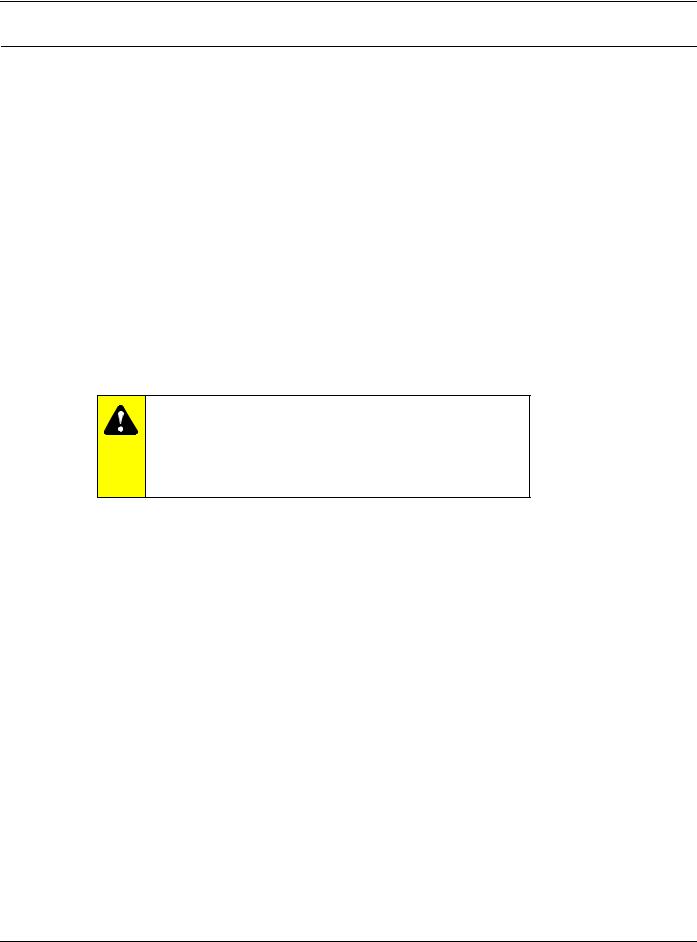
Model 5600 Installation and Start-up Procedures
NOTE: Install the water softener with the inlet, outlet and drain connections made according to manufacturer’s recommendations and to meet applicable plumbing codes.
Manual |
|
Regeneration Knob |
24-Hour Gear |
|
Skipper Wheel |
Red Time |
(shows every |
Set Button |
other day |
|
regeneration) |
Time of Day Arrow |
Red Pointer |
Figure 1: Model 5600 Softener Control
1.Manually index the softener control into the In Service position and let water flow into the resin tank. When the water flow stops, open a softened water tap until all air is released from the lines. Then close tap.
NOTE: Manually dial the various regeneration positions by turning the knob on the front of the control until the indicator shows that the softener is in the desired position.
2.Manually index the control to the Backwash position and allow water to flow at the drain for 3 or 4 minutes.
3.Remove back cover plate.
4.Make sure that the salt dosage is set as recommended by the manufacturer. If necessary, set salt according to the setting instruction sheet. Manually index the control to the Brine Fill position and allow the brine tank to fill to the top of the air check.
5.Manually index the control to the Brine Draw position and allow the control to draw water from the brine tank until it stops.
6.Plug in the electrical cord and look in the sight hole in the back of the motor to see that it is running. Set the days that regeneration is to occur by sliding tabs on skipper wheel outward to expose trip fingers.
—Each tab is one day.
—Finger at red pointer is tonight.
—Moving clockwise from red pointer, extend or retract fingers to obtain the desired regeneration schedule.
7.Manually advance the control to the beginning of the Brine Fill position and allow the control to return to the In Service position automatically.
8.Fill the brine tank with salt.
9.Replace back cover on the control.
10.Make sure that any bypass valving is left in the normal In Service position.
6
Model 5600 & 5600 Econominder®
Model 5600 Backwash Filter Installation and Start-up Procedures
NOTE: Install the water softener with the inlet, outlet and drain connections made according to manufacturer’s recommendations and to meet applicable plumbing codes.
Manual |
|
|
Regeneration Knob |
24-Hour Gear |
|
|
Skipper Wheel |
|
Red Time |
(shows every |
|
other day |
||
Set Button |
||
backwash) |
||
|
Time of Day Arrow |
Red Pointer |
Figure 2: Model 5600 Backwash Filter Control
Before Plugging in the Unit
1.Open a treated water tap down stream of the filter.
2.Manually index the filter to the In Service position and allow the mineral tank to fill by slowly opening the main water supply valve. Any bypass should be in the In Service position.
NOTE: The water flowing from the downstream tap is cloudy and/or contains media fines as well as air. Allow the water to run until it appears clean and free of air.
3.When a steady clean flow appears at the tap, close the tap and the main water supply valve and allow the filter media bed to settle for 15–20 minutes.
4.Manually index the filter to the Backwash position.
5.To prevent a sudden surge of water and air, partially open the main water supply valve so that the flow at the drain of the filter is approximately 1 gpm. The water at the drain is cloudy again and/or contains media fines as well as air. Allow water to flow at the drain until it appears clean and free of air.
6.Continue to open the water supply valve until it is completely open. Allow water to flow at the drain until all media fines are washed out of the filter.
7.Manually index the filter to the In Service position, and again open the downstream tap. Check to be sure that the water flows clear. If necessary, allow water to flow until all media fines are gone. If the tap is equipped with an aerator check that is not plugged with media fines and pipe scale.
8.Plug in the electrical cord and look in the sight hole on the back of the timer motor to ensure that it is running. Set the days backwashing is to occur by sliding tabs on the skipper wheel outward to expose trip fingers. Each tab is one day. Finger at red pointer is tonight. Moving clockwise from red pointer, extend or retract fingers to obtain the desired backwash schedule.
9.Set time of day by pushing red button and spin the 24-hour gear until the present time of day is visible above the time of day arrow.
7

Model 5600 & 5600 Econominder®
Model 5600 Backwash Filter Installation and Start-up Procedures (Cont’d.)
Cycle Times and Flow Diagrams
1.In Service position. See Figure 4, page 10.
2.Preliminary Rinse position.
—Same as Figure 4, page 10 with standard piston (white end plug) or filter piston (black end plug).
—Eliminated with low water piston (gray end plug).
3.Backwash position.
—Same as Figure 6, page 11 with standard piston.
—15 minutes with filter piston.
—7 minutes with low water piston.
4.Brine Rinse position.
—Eliminated, resulting in a 50 minute pause, no water flows during this time.
5.Slow Rinse position.
—Eliminated, resulting in a 50 minute pause, no water flows during this time.
6.Second Backwash position.
—Same as Figure 9, page 12 with standard piston.
—15 minutes with filter piston.
—7 minutes with low water piston.
7.Settling Rinse position.
—Same as Figure 10, page 13 with standard or filter piston.
—Eliminate with low water piston.
8.Brine Tank Refill position.
—Eliminated, filter is back in service at this time.
8
Model 5600 & 5600 Econominder®
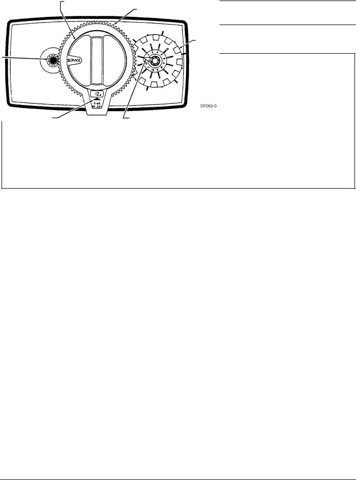
Model 5600 Econominder Installation and Start-up Procedures
NOTE: Install the water softener with the inlet, outlet and drain connections made according to manufacturer’s recommendations and to meet applicable plumbing codes.
Manual Regeneration Knob |
24-Hour Gear |
Program Wheel |
|
|
|
Red Time |
|
People Dial |
|
|
|
Set Button |
|
Grains Per Gallon |
|
|
Water Hardness |
|
|
Scale |
|
White Dot |
Gallons Label |
|
|
|
|
Figure 3: Model 5600 Econominder |
|
1.Manually index the softener control to the In Service position and let water flow into the resin tank. When the water flow stops, open a softened water tap until all air is released from the lines. Then close tap.
NOTE: The various regeneration positions may be dialed manually by turning the knob on the front of the control until the indicator shows that the softener is in the desired position.
2.Set water usage program wheel using any one of the following procedures:
—Typical Residential Application
To program, just set the time, set the hardness and it automatically monitors system needs and regenerates only when necessary. To set time of day press red time set button and turn 24-hour gear until present time of day is at “time of day.” Set program wheel by lifting the “people” dial and rotating it so that the number of people in the household is aligned with the household grains per gallon water hardness. Release the dial and check for firm engagement at setting. This method provides reserve capacity based on 75 gallons per person.
—Optional Programming Procedures
Calculate the gallon capacity of the system, subtract the necessary reserve requirement and set the gallons available at the small white dot on program wheel gear. Note, drawing shows 850 gallon setting. The capacity (gallons) arrow denotes remaining gallons exclusive of fixed reserve.
3.Rotate program wheel counterclockwise until it stops at Regeneration position.
4.Manually index the control to the Backwash position and allow water to flow at the drain for 3 or 4 minutes.
5.Remove back cover plate.
6.Make sure than the salt dosage is set as recommended by the manufacturer. Manually index the control to the Brine Fill position and allow the brine tank to fill to the top of the air check.
7.Manually index the control to the Brine Rinse position and allow the control to draw water from the brine tank until it stops.
8.Plug in the electrical cord and look in the sight hole in the back of the monitor to see that it is running.
9.Manually advance the control to the beginning of the Brine Fill position and allow the control to return to the In Service position automatically.
10.Fill the brine tank with salt.
11.Replace back cover on the control. Be sure cable is not pinched between cover and housing.
12.Make sure that any bypass valving is left in the normal In Service position.
9
Model 5600 & 5600 Econominder®
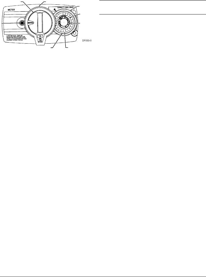
Water Conditioner Flow Diagrams
Service Position
Figure 4: Service Position
Preliminary Rinse Position
Figure 5: Preliminary Rinse Position
10
Model 5600 & 5600 Econominder®
Water Conditioner Flow Diagrams (Cont’d.)
Backwash Position
Figure 6: Backwash Position
Brine Position
Figure 7: Brine Position
11
 Loading...