


IMP521-1IS
Pelco IMP521-1IS, IMP521-1ES, IMP321-1RS, IMP321-1IS, IMP321-1ES User Manual
...
C2292M-B-EN (12/16)
IMP121-1IS
IMP221-1IS
IMP321-1IS
IMP521-1IS
Sarix
®
Professional IMP
Series 3.75” Indoor Dome
User Manual
C2292M-B-EN (12/16)
IJP121-1IS
IJP221-1IS
Sarix
®
Professional IJP
Series 2” Micro Indoor Dome
User Manual
2

Contents
Important Notices Statement ........................................................................................................................................................ 5
Regulatory Notices .............................................................................................................................................................. 5
Radio and Television Interference ....................................................................................................................................... 5
Korean Class A EMC .................................................................................................................................................. 5
Warranty Statement ..................................................................................................................................................................... 5
UL Safety Notices ................................................................................................................................................................ 5
Preface ......................................................................................................................................................................................... 6
1. Product Overview .............................................................................................................................................................. 7
1.1 Dimensions .................................................................................................................................................................... 7
1.1.1 IMP Series 3.75” Indoor Dome ........................................................................................................................... 7
1.1.2 IJP Series 2” Micro Indoor Dome ....................................................................................................................... 7
1.2 Models Introduction ....................................................................................................................................................... 8
1.2.1 IMP Series 3.75” Indoor Dome ........................................................................................................................... 8
1.2.2 IJP Series 2” Micro Indoor Dome ....................................................................................................................... 8
1.3 Physical Characteristics ................................................................................................................................................. 9
1.3.1 IMP Series 3.75” Indoor Dome ........................................................................................................................... 9
1.3.2 IJP Series 2” Micro Indoor Dome ..................................................................................................................... 11
2. Installation and Connection ........................................................................................................................................ 12
2.1 Unpacking Everything .................................................................................................................................................. 12
2.1.1 IMP Series 3.75” Indoor Dome ......................................................................................................................... 12
2.1.2 IJP Series 2” Micro Indoor Dome ..................................................................................................................... 12
2.2 Optional Accessories ................................................................................................................................................... 13
2.2.1 IMP Series 3.75” Indoor Dome ......................................................................................................................... 13
2.2.2 IJP Series 2” Micro Indoor Dome ..................................................................................................................... 13
2.3 Installation - IMP Series 3.75” Indoor Dome ................................................................................................................ 13
2.3.1 Checking Appearance ...................................................................................................................................... 13
2.3.2 Disassembling the Camera .............................................................................................................................. 14

2.3.3 Connecting the Wires ....................................................................................................................................... 15
2.3.4 Mounting the Camera ....................................................................................................................................... 15
2.3.5 Adjusting the Camera Position ......................................................................................................................... 22
2.3.6 Adjusting the Focus .......................................................................................................................................... 23
2.3.7 Network Topology ............................................................................................................................................ 23
2.3.8 System Requirements ...................................................................................................................................... 24
2.4 Installation - IJP Series 2” Micro Indoor Dome ............................................................................................................. 25
2.4.1 Checking Appearance ...................................................................................................................................... 25
2.4.2 Disassembling the Camera .............................................................................................................................. 25
2.4.3 Connecting the Wires ....................................................................................................................................... 26
2.4.4 Mounting the Camera ....................................................................................................................................... 27
2.4.5 Adjusting the Camera Position ......................................................................................................................... 30
2.4.6 Network Topology ............................................................................................................................................ 30
2.4.7 System Requirements ...................................................................................................................................... 31
2.5 Connection ................................................................................................................................................................... 32
2.5.1 Default IP address ............................................................................................................................................ 32
2.5.2 Connecting From a Computer & Viewing Preparation ...................................................................................... 32
3. Administration and Configuration .............................................................................................................................. 34
3.1 Live .............................................................................................................................................................................. 34
3.1.1 Zoom and Focus Controls ................................................................................................................................ 35
3.2 Settings ........................................................................................................................................................................ 35
3.2.1 System ............................................................................................................................................................. 36
3.2.2 Network ............................................................................................................................................................ 39
3.2.3 Imaging ............................................................................................................................................................. 51
3.2.4 A/V Streams ..................................................................................................................................................... 59
3.2.5 Users ................................................................................................................................................................ 65
3.2.6 Events .............................................................................................................................................................. 68
Pelco Troubleshooting Contact Information ............................................................................................................................... 79
4
Important Notices Statement
For information about Pelco’s product-specific important notices and thereto related information, refer to www.pelco.com/legal.
REGULATORY NOTICES
This device complies with Part 15 of the FCC Rules. Operation is subject to the following two conditions: (1) this device may
not cause harmful interference, and (2) this device must accept any interference received, including interference that may
cause undesired operation.
RADIO AND TELEVISION INTERFERENCE
This equipment has been tested and found to comply with the limits of a Class A digital device, pursuant to Part 15 of the FCC
rules. These limits are designed to provide reasonable protection against harmful interference when the equipment is operated
in a commercial environment. This equipment generates, uses, and can radiate radio frequency energy and, if not installed
and used in accordance with the instruction manual, may cause harmful interference to radio communications. Operation of
this equipment in a residential area is likely to cause harmful interference in which case the user will be required to correct the
interference at his own expense.
Changes and Modifications not expressly approved by the manufacturer or registrant of this equipment can void your authority
to operate this equipment under Federal Communications Commission’s rules.
CAN ICES-3(A)/NMB-3(A)
Korean Class A EMC
Warranty Statement
For information about Pelco’s product warranty and thereto related information, refer to www.pelco.com/warranty.
UL SAFETY NOTICES
The product is intended to be supplied by a Listed Power Unit marked "L.P.S." (or "Limited Power Source") and rated output
12Vdc/0.70A or 24Vac, 0.56A minimum or 48Vdc, 0.15A minimum.
The product shall be installed by a qualified service person and the installation shall conform to all local codes.
5

Preface
This user manual is to be used as a reference for the installation and manipulation of the camera unit including features,
functions, and a detailed explanation of the menu tree.
This manual provides the following information:
Product Overview: The main functions and system requirements of the unit.
Installation and Connection: Instructions on unit installation and wire connections.
Administration and Configuration: The main menu navigation and controls explanations.
6
1. Product Overview
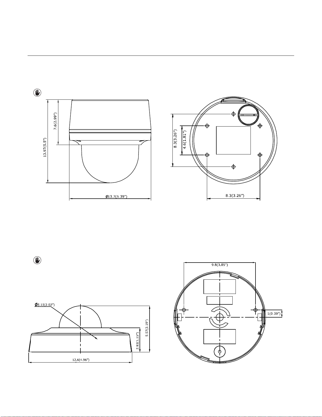
1.1 Dimensions
1.1.1 IMP Series 3.75” Indoor Dome
The dimension of the Sarix® Professional Series 3.75” Indoor Dome camera is depicted within the Figure 1-1 below.
VALUES IN PARENTHESES ARE INCHES; ALL OTHERS ARE
FIGURE 1-1: PHYSICAL DIMENSIONS
1.1.2 IJP Series 2” Micro Indoor Dome
CENTIMETERS.
3.75” INDOOR DOME
The dimension of the Sarix® Professional Series IP 2” Micro Indoor Dome camera is depicted within the Figure 1-2 below.
VALUES IN PARENTHESES ARE INCHES; ALL OTHERS ARE
FIGURE 1-2: PHYSICAL DIMENSIONS
7
CENTIMETERS.
2” MICRO INDOOR DOME

1.2 Models Introduction
Model
Description
IMP121-1ES
1MP Indoor Dome with Vari-focal lens
IMP221-1ES
2MP Indoor Dome with Vari-focal lens
IMP321-1ES
3MP Indoor Dome with Vari-focal lens
IMP521-1ES
5MP Indoor Dome with Vari-focal lens
Model
Description
IJP121-1IS
1MP 2” Micro Indoor Dome
IJP221-1IS
2MP 2” Micro Indoor Dome
1.2.1 IMP Series 3.75” Indoor Dome
The physical appearance and installation methods for the IMP 3.75” Indoor Series models indicated within the list below are,
by and large, the same. Therefore, please regard this manual where we use the example from IMP521-1IS as a reference to
apply to all the varied models.
TABLE 1-1: MODELS LIST
1.2.2 IJP Series 2” Micro Indoor Dome
The physical appearances and installation methods for the IJP 2” Indoor models indicated within the list below are, by and
large, the same. Therefore, please regard this manual where we use the example from IJP221-1IS as a reference to apply to
all the models.
TABLE 1-2: MODELS LIST
8
1.3 Physical Characteristics
1
2 3 4 5 6
7 8 10
11
12
13
9
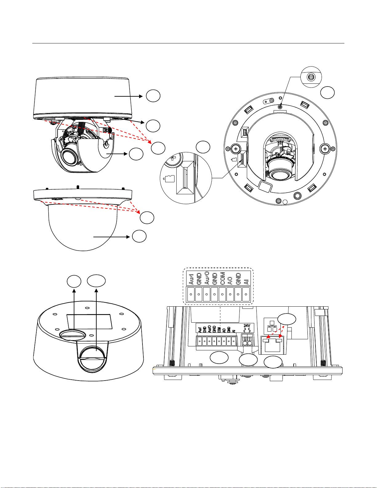
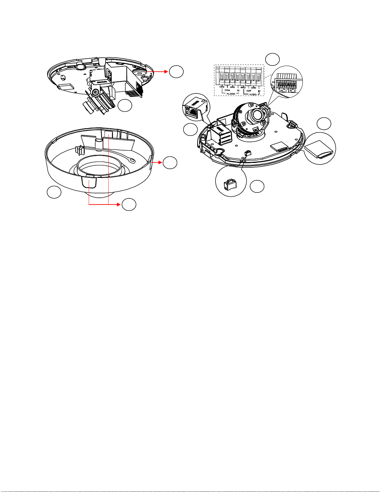
1.3.1 IMP Series 3.75” Indoor Dome
FIGURE 1-3: CAMERA CONNECTIONS AND FEATURES 1/4 FIGURE 1-4: CAMERA CONNECTIONS AND FEATURES 2/4
FIGURE 1-5: CAMERA CONNECTIONS AND FEATURES 3/4 FIGURE 1-6: CAMERA CONNECTIONS AND FEATURES 4/4
1. Back box: The bottom case of the camera.
2. Lens Base: The physical main body of the camera.
3. Torx Screws of Lens Base * 3: The screws for fixing lens base with back box.
4. Inner Liner: The inner adjustable liner to cover and beautify camera lens assembly.
9

5. Torx Screws of Top Cover * 3: The screws for fixing top cover with lens base.
6. Top Cover: The top cover of the camera.
7. Micro SD Card Slot: The slot is for inserting micro SD card for file storage.
8. Default & Reset Button:
Default: Press the button for 6 seconds to restore the camera’s settings back to the factory default.
Reset: Press the button for below 1 second to reboot the camera.
9. Bottom Conduit Hole: The bottom hole for cable entry.
10. Side Conduit Hole: The side hole for cable entry.
11. Digital I/O Connectors:
Audio In: Via “Au/I” and “GND” ports, connect to external device like microphone that receives sound for camera.
Audio Out: Via “Au/O” and “GND” ports, connect to device like speaker to be triggered through alarm output signals.
Alarm Out: Via “COM” and “AO” ports, connect to external device to be triggered through alarm output signals.
Alarm In: Via “GND” and “AI” ports, connect to external device that can trigger alarm input signals.
12. Power Terminal: The port is to connect with external either DC 12V or AC 24V power supply.
13. RJ-45 Network Port: Connect the RJ-45 connector to this port with a PoE (Class 2) compatible network
device that supplies power through the Ethernet cable.
14. LED Indicators:
Green LED: With solid green, the LED indicates a live connection is established.
Orange LED: With flashing orange, the LED indicates data is being transmitted / received between camera
and Internet.
10
1.3.2 IJP Series 2” Micro Indoor Dome
1 2 3
4 5 6 7 8
9
FIGURE 1-7: CAMERA CONNECTIONS AND FEATURES 1/2 FIGURE 1-8: CAMERA CONNECTIONS AND FEATURES 2/2
1. Camera Body: The physical main body of the camera.
2. Bottom Conduit Hole: The conduit hole designed for bottom conduit cabling.
3. Top Cover: The upper dome cover for the camera.
4. Latch Buttons: The 2 latch bottoms along the 2 sides of top cover are the cruxes to disassemble the camera.
5. Side Conduit Hole: The conduit hole designed for side conduit cabling.
6. RJ-45 Network Port: Connect the RJ-45 connector to this port with a PoE (Class 2) compatible network
device that supplied power through the Ethernet cable.
7. Default & Reset Button:
Default: Press the button for 6 seconds to restore the camera’s settings back to the factory default.
Reset: Press the button for below 1 second to reboot the camera.
8. Micro SD Card Slot: The slot is for inserting micro SD card for file storage.
9. Digital I/O Connectors:
Alarm Out: Via “OUT” and “COM” ports, connect to external device to be triggered through alarm output signals.
Alarm In: Via “GND” and “IN” ports, connect to external device that can trigger alarm input signals.
Audio Out: Via “GND” and “OUT” ports, connect to device like speaker to be triggered through alarm output signals.
Audio In: Via “GND” and “IN“ ports, connect to external device like microphone that receives sound for camera.
11

2. Installation and Connection
2.1 Unpacking Everything
2.1.1 IMP Series 3.75” Indoor Dome
Check all items in the product box against the order form and the packing slip. In addition to this manual, the items below are
included in the product box:
3.75” Indoor Dome camera * 1
Plastic Anchor * 4
Flat Head Screw (Tapping Type) * 4
T10 Security Torx Wrench * 1
Mounting Template * 2
Terminal Block * 1
Conduit Hole Plug * 1
Important Notices Declaration * 1
Printed Quick Start Guide * 1
Supplemental Resources Sheet * 1
Important Safety Instruction * 1
ROHS Statement Slip * 1
Please contact your dealer if any items are missing.
2.1.2 IJP Series 2” Micro Indoor Dome
Check all items in the product box against the order form and the packing slip. In addition to this manual, the items below are
included in the product box:
Fixed Indoor Dome Camera * 1
Plastic Anchor * 2
Flat Head Screw (Tapping Type) * 2
Mounting Template * 1
Important Notices Declaration * 1
Printed Quick Start Guide * 1
Supplemental Resources Sheet * 1
Important Safety Instruction * 1
ROHS Statement Slip * 1
Please contact your dealer if any items are missing.
12

2.2 Optional Accessories
2.2.1 IMP Series 3.75” Indoor Dome
IMPICM-1l: In-ceiling wall mount, for use with the indoor dome models
IMPPM-1l: Pendant adapter, for use with the indoor dome models
IMPLD2-0I: Lower dome (smoked)
IMPLD2-1I: Lower dome (clear)
2.2.2 IJP Series 2” Micro Indoor Dome
IMPEBAP: 4S electrical box adapter for micro dome models
IMPPMB-1I: Wall mount L-shape bracket for micro indoor dome models
2.3 Installation - IMP Series 3.75” Indoor Dome
Following tools might help you complete the installation:
A drill
Screwdrivers
Wire cutters
2.3.1 Checking Appearance
Although the protective materials used for the packaging should be able to protect the unit from most accidents during
transportation, check the unit and its accessories for any visible damage. Remove the protective film to check items in
accordance with the list in 2.1 Unpacking Everything.
13
2.3.2 Disassembling the Camera
2
1 3 4
Please refer to the steps with the figure below for the correct disassembling order.
1. Loosen the 3 camera top cover screws.
2. Gently pull the top cover downward to take it apart from the camera body.
3. Further loosen the 3 camera lens base screws.
4. Gently lift the camera lens base off from the back box.
FIGURE 2 - 1: DISASSEMBLING THE CAMERA
14

2.3.3 Connecting the Wires
1. Loosen the 3 top cover
screws by torx wrench
(supplied) followed by
removing the top cover.
2. Lift to open the inner liner.
3. Loosen another 3 screws of
camera lens base via torx
wrench (supplied).
4. Remove the lens base from
theback box.
1
4
3
2
After disassembling, the I/O interfaces will be seen on the rear of the lens base.
Connect the power cable to the power port via one of the following 3 alternatives.
AC 24V: Connect a power cable that supplies AC24V power source to the power terminal.
DC 12V: Connect a power cable that supplies DC12V power source to the power terminal.
PoE (Class 2): Connect an Ethernet cable terminated with RJ-45 connector to the PoE RJ-45 port for both power
supply and network connectivity purposes simultaneously.
Insert audio in/out cables and alarm in/out cables to the corresponding terminals of the camera if required.
FIGURE 2 - 2: REAR SIDE FOR WIRING CONNECTION
2.3.4 Mounting the Camera
Step 1. Preparation by Disassembling
Remove the camera housing, inner liner and bottom case.
15
FIGURE 2 - 3: DISASSEMBLING THE CAMERA
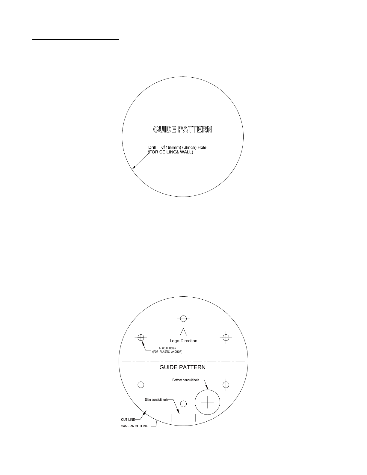
Step 2. Mark Mounting Area
T2
T2
T1
T1
T1
T1
Use the guide pattern to prepare a mounting area for In-Ceiling Flush Mount.
1. Attach the mounting template on a desired mounting surface (normally for in-ceiling).
2. Drill a round hole (∅198mm) based on the template on the surface to have the camera embedded within the hole later.
FIGURE 2 - 4: MOUNTING TEMPLATE FOR FLUSH MOUNT
Use the mounting template to prepare a mounting area for Surface Mount.
1. Place the supplied mounting template on a mounting surface. Drill 6 mm (0.2”) outer holes at the T1 or T2 template
positions on the mounting surface. Then insert 4 or 2 supplied plastic anchors into the holes. (T1: for single-gang socket,
T2: for double-gang socket, if applicable on mounting surface)
2. If you want to feed wiring from the hole on the top of the back box, create a circular opening corresponding to the
“Bottom conduit hole” of mounting template on the mounting surface.
3. If feeding wiring from the side of the back box, you don’t need to drill a hole on the mounting surface. The “Side conduit
hole” indication on the mounting template is for user to identify while mounting.
FIGURE 2 - 5: MOUNTING TEMPLATE FOR SURFACE MOUNT
16

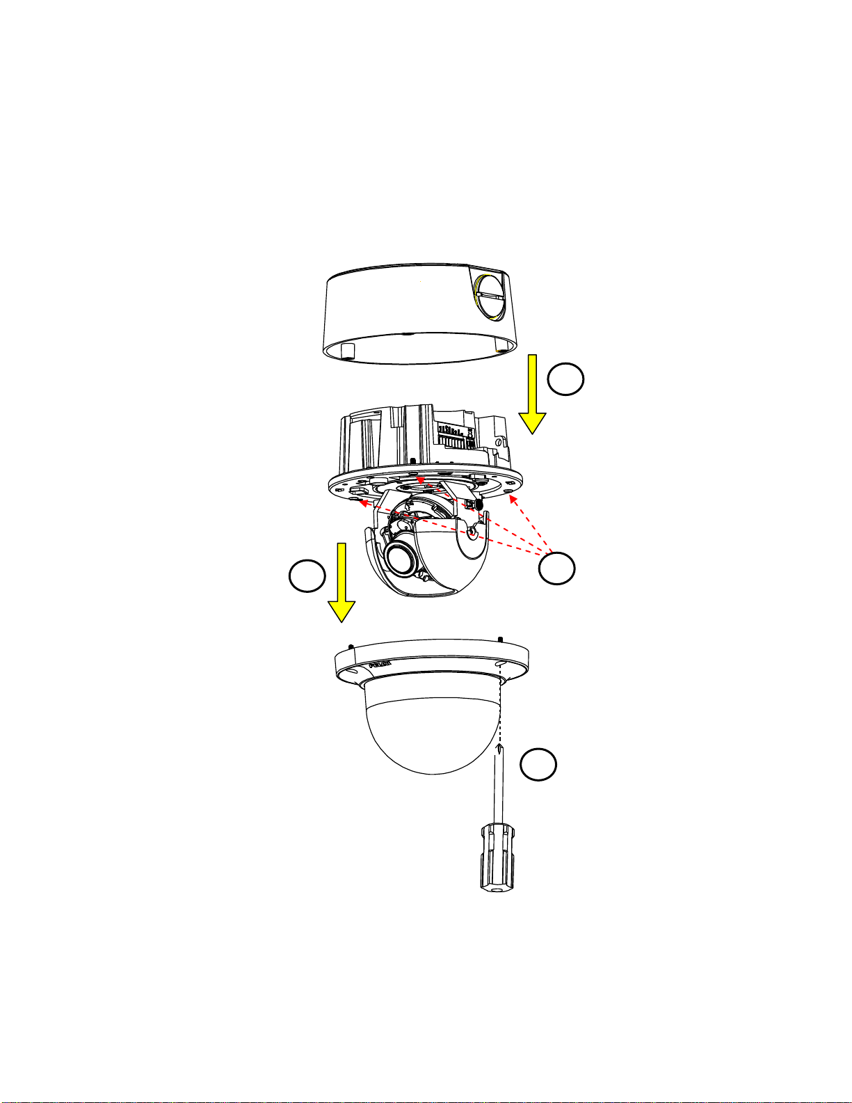
Step 3. Mounting Schemes
Locking Arms
Tighten the screws to
extend the locking arms
Method 1: Flush Mount (requires In-Ceiling mounting accessory)
1. Embed the in-ceiling mount bracket into the hole that was drilled based on the mounting template.
FIGURE 2 - 6: FLUSH MOUNT 1/3
2. Use a cross screw driver to turn the 2 bracket screws clockwise to extend the locking arms and tighten them
securely to compress the locking arms so that the bracket can be fixed within the in-ceiling area firmly.
17
FIGURE 2 - 7: FLUSH MOUNT 2/3
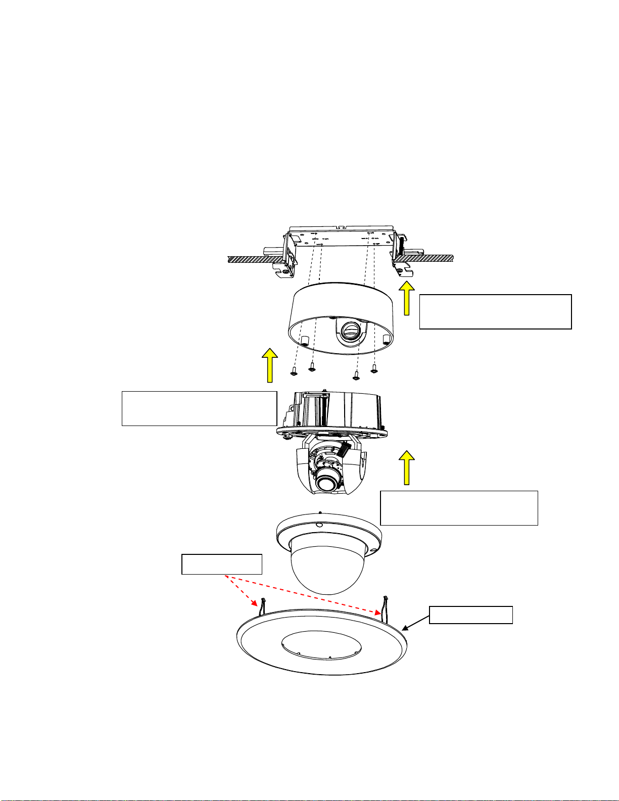
3. Based on your needs, use the bottom conduit hole or side conduit hole on the back box for cable entry and
Protective Cover
Spring Hook * 2
Fix back box onto the in-ceiling
bracket by securing the 4 screws.
Assemble lens base with lower
case and fasten the 3 torx screws.
Further mount top cover onto lens
base and tighten the 3 torx screws.
connect the required cables.
NOTE: Please properly lock the conduit hole plug on the unused hole. For example, lock the side conduit hole
with the plug while using the bottom conduit hole for cable entry and vice versa.
4. Fix the back box onto the in-ceiling bracket by fastening the 4 screws followed by aligning the identifying red
dots of back box and lens base to properly assemble them together with securing the 3 lens base screws.
5. After adjusting focus position to the satisfied field of view, mount the top cover on the lens base, both of which
have a red dot respectively also for aligning identification and tighten the 3 top cover screws firmly.
6. Attach the 2 spring hooks flanked the protective cover to the in-ceiling bracket for mounting completion.
NOTE: It is strongly recommended that you first ensure the mounting area is stable enough to withstand the in-ceiling
bracket and locking arms clamping on the ground of safety concern.
18
FIGURE 2 - 8: FLUSH MOUNT 3/3
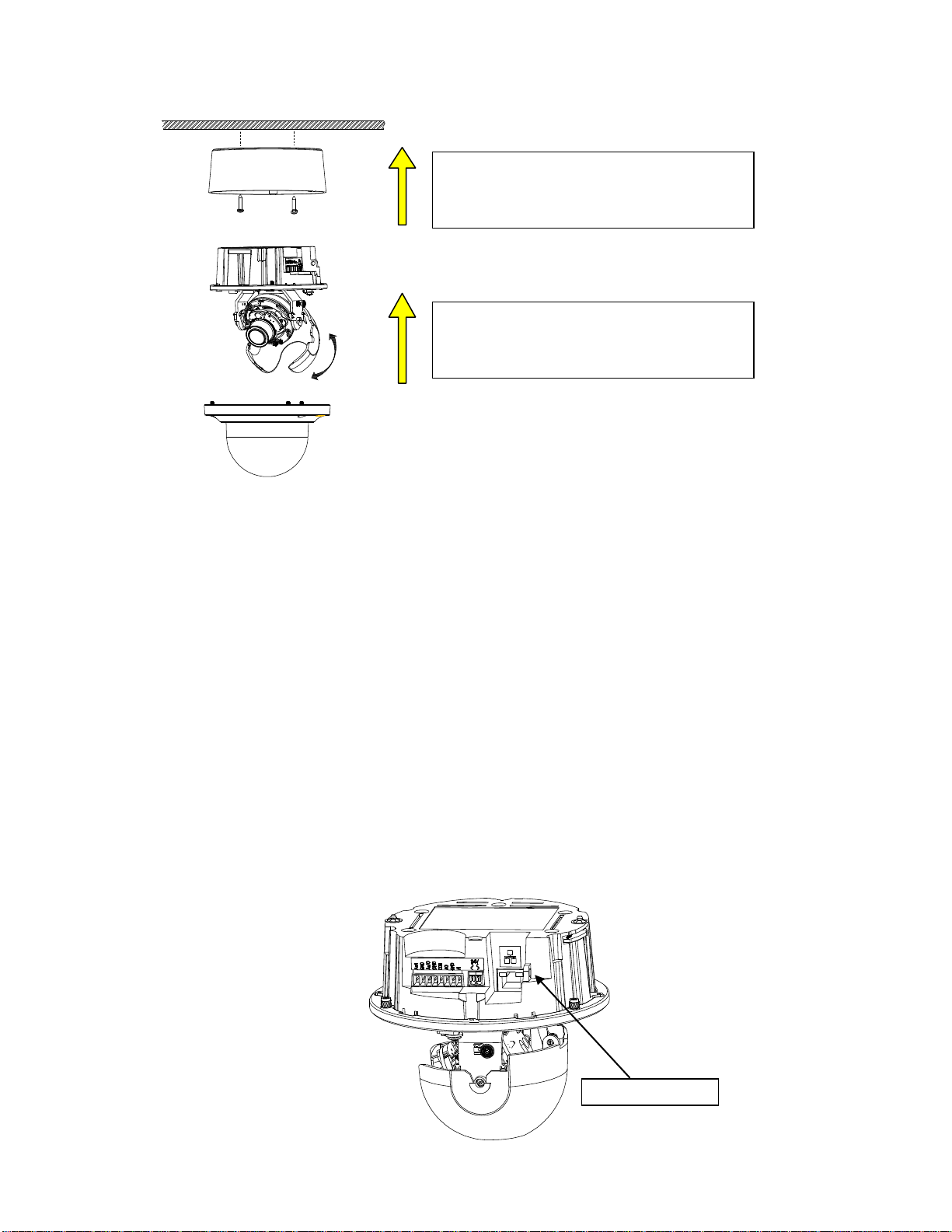
Method 2: Surface Mount
After cable entry and wiring, align the red dots
of back box and lens base followed by securing
the torx screws tightly.
After adjusting focus angle, align the red dots of
lens base and top cover followed by fastening
the torx screws to complete the procedure.
Safety-cord screw
FIGURE 2 - 9: SURFACE MOUNT
1. Based on your needs, use the bottom or side conduit hole on the back box for cable entry and connect the
required cables first. Then mount the back box on a surface by securing screws (supplied) into the inserted
plastic anchors tightly.
2. Align the back box and the lens base, both of which have a red dot on the top side respectively for aligning
identification. Use the red dots to properly align them and then securely fasten the 3 screws of the lens base to
the bottom case with torx key (supplied).
3. Adjust the focusing position by rotating, panning and tilting the camera lens base. When rotating the camera
lens, do not rotate it over the stop point.
4. Fit the inner liner over the camera lens base until it snaps into the place.
5. Mount the top cover on the lens base, both of which similarly have a red dot for aligning identification. Be
aware that the red dot of top cover is within interior instead of top side.
6. Use the torx wrench (supplied) to tighten the 3 top cover screws to complete mounting.
NOTE: Please properly lock the conduit hole plug on the unused hole. For example, lock the side conduit hole with
the plug while using the bottom conduit hole for cable entry and vice versa.
If you possess a safety wire (sold separately), connect the safety wire with one end to the mounting surface
and the other end to the safety-cord screw of the camera in case of accidentally falling off.
FIGURE 2 -10: SAFETY-CORD SCREW
19
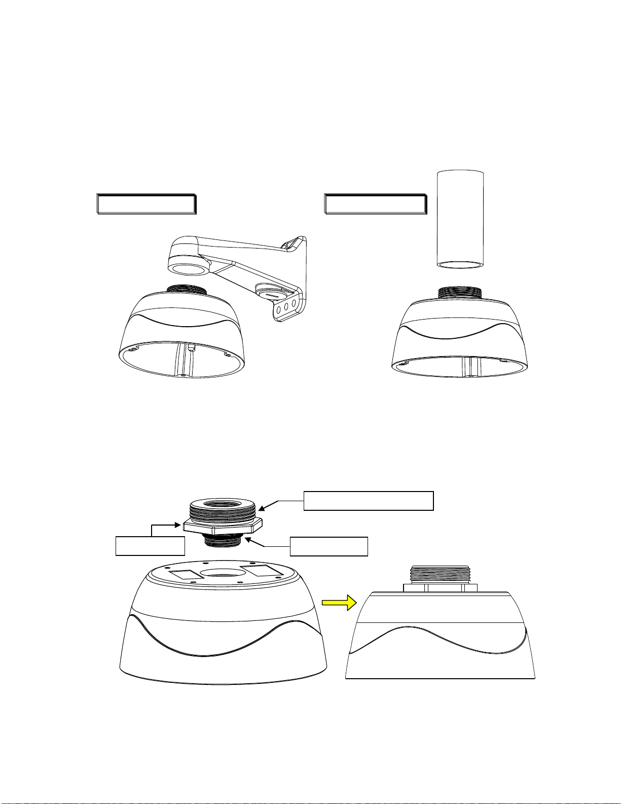
Method 3: Pendant Mount (requires pendant adapter mounting accessory)
Adaptor Ring
Apply Waterproof Repellent
Rubber O-Ring
Pendant Wall Mount
Pendant Pole Mount
The Pendant Installation involves mounting IMPPM-1l Sarix Indoor Pendant Mount for Indoor Dome camera. The
camera must be first installed within the pendant mount back box with an adaptor ring before assembled with
additional pendant mount brackets. Below are the recommended brackets, which are NOT provided, for additional
pendant mount applications for your reference.
NOTE: Mounts and conduits must be sealed to prevent condensation in the camera
FIGURE 2-10: PENDANT MOUNT APPLICATIONS
1. Rotate the adaptor ring, which can connect with brackets of 1 1/2”-conform screw thread, clockwise to the pendant
mount back box securely as shown below. The rubber o-ring provides seal on grooves between back box and
adaptor ring. Note that it is highly suggested to apply waterproof repellent onto the upper screw thread as shown
below for complete ingress protection. The diagram in the right side is the back box mounted with the adaptor ring.
20
FIGURE 2 -11: PENDANT MOUNT 1/2
NOTE: Anti-seize compound should be applied on pendant mount. Not doing so might prevent the unit from
being separated in the future. Waterproof tape can also be used to help prevent water ingress damage.
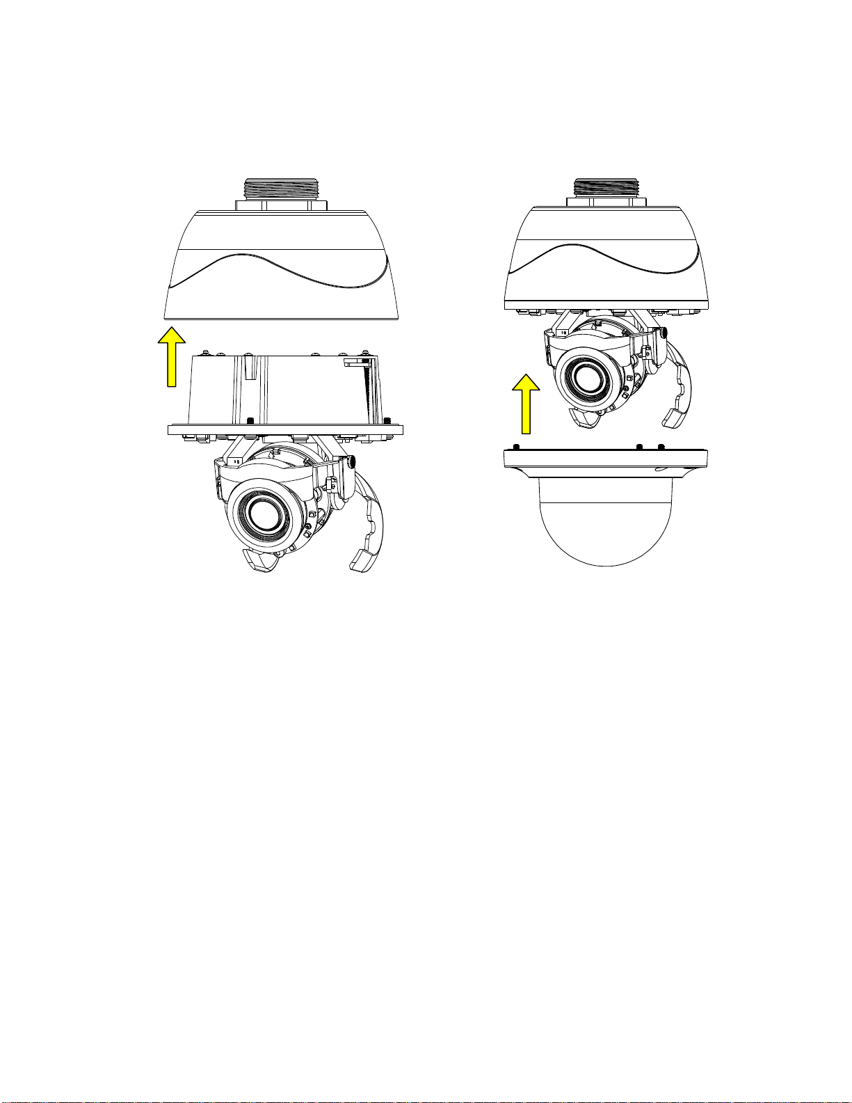
2. After wires connection, attach the lens base to the pendant mount back box by aligning the red dots for
identification of both parts and securely fasten the 3 screws of the lens base with the torx wrench (supplied).
Finally, assemble the top cover with the lens base, both of which, similarly, have red dots for aligning
identification, followed by fastening the 3 screws of top cover to complete the installation.
FIGURE 2 -13: PENDANT MOUNT 2/2
21
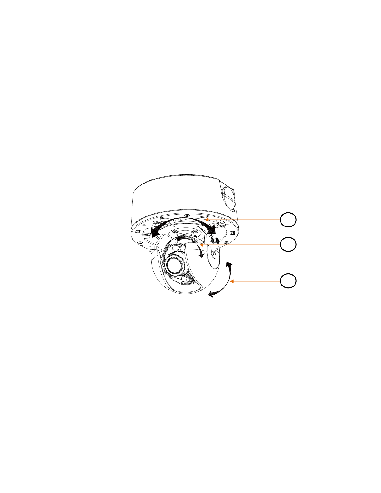
2.3.5 Adjusting the Camera Position
A B C
The camera has three axes for adjusting field of view on different applications. While screening live view on your monitor,
adjust the position using the procedures below simultaneously for desired focusing position.
Pan Adjustment (A)
Rotate the lens base until you are satisfied with the field of view. Note that the side conduit hole of back box is the point
where the camera lens shouldn’t be rotated over.
Horizontal Rotation (B)
Rotate 3D assembly in the lens base, but do not turn assembly more than 355° as this may have the internal cables
twisted, disconnected, or broken.
Tilt Adjustment (C)
Lift to open the inner liner, and tilt the camera lens to your desired angle. Restore the inner liner back to its default
position after adjustment.
NOTE: Limitation for three axes position: Pan range: ±177°, Rotate range: ±177°, Tilt range: 35°~ 90°
FIGURE 2 – 14: ADJUSTING THE CAMERA POSITION
22
2.3.6 Adjusting the Focus
1. View the camera image using the browser (refer to 2.5 Connection on page 32).
2. Use the settings in the Web interface (refer to 3.2.3.4 Focus on page 56) to adjust the zoom and focus of the lens to the
desired field of view.
3. Also, the focus can be adjusted by moving the zoom slider and using the Focus options in the live webpage.
NOTE: Focus adjustment is done exclusively with Web UI.
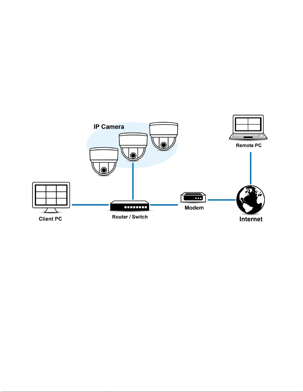
2.3.7 Network Topology
The unit, which is equipped with Ethernet RJ-45 network interface, can deliver video images in real time via either Internet or
Intranet. Please refer to the skeleton drawings shown below to enhance your understanding.
FIGURE 2-15: NETWORK TOPOLOGY
23

2.3.8 System Requirements
System Hardware
CPU
Intel® Pentium® 4 microprocessor, 2.4GHz or equivalent
RAM
1 GB or above
Monitor
Minimum of 1024 x 768 resolution, 16- or 32-bit pixel color resolution
System Software
Operating System
Microsoft Windows XP, Vista 32 and 64 bit, Win7 32 and 64 bit
Browser
Microsoft IE 9.0 and later
Media Player
Pelco Media Player or QuickTime® 7.6.5 for Windows XP, Windows Vista, and Windows 7; or
QuickTime 7.6.4 for Mac OS X 10.4 (or later)
Unit
Power Supply
PoE / AC 24V /DC 12V
Note
1. All the installation and operations should comply with your local electricity safety rules.
2. Pelco Media Player is recommended for control, smoothness, and reduced latency as compared to
QuickTime. The PMP is downloadable from Pelco web site: www.pelco.com/mediaplayer.
3. This product is not compatible with QuickTime version 7.6.4 for Windows XP or Windows Vista. If
you have this version installed on your PC, you will need to upgrade to QuickTime version 7.6.5.
4. Network and processor bandwidth limitations might cause the video stream to pause or appear
pixelated when additional Web-interface users connect to the camera. Decrease the images per
second (ips), resolution, compression, or bit rate settings of the Web interface video streams to
compensate for network or processor limitations.
The table below lists the minimum requirements to implement and operate a unit. Network and processor bandwidth limitations
might cause the video stream to pause or appear pixilated when additional Web-interface users connect to the camera.
Decrease the images per second (ips), resolution, compression, or bit rate settings of the Web interface video streams to
compensate for network/processor limitations.
TABLE 2-1: SYSTEM REQUIREMENTS
24
 Loading...