


Pelco IMP521-1RS, IMP521-1ES, IMP321-1RS, IMP321-1ES, IMP221-1ES User Manual
...Sarix® Professional IMP
Series Environmental Vandal
Dome
User Manual
IMP121-1ES IMP321-1ES
IMP121-1RS IMP321-1RS
IMP221-1ES IMP521-1ES
IMP221-1RS IMP521-1RS
C2294M-A-EN (1/16)
2
Contents |
|
|
Important Notices Statement........................................................................................................................................................ |
5 |
|
Warranty Statement ..................................................................................................................................................................... |
5 |
|
Preface......................................................................................................................................................................................... |
|
6 |
1. Product Overview.............................................................................................................................................................. |
6 |
|
1.1 |
Dimensions .................................................................................................................................................................... |
6 |
1.2 |
Models Introduction ....................................................................................................................................................... |
7 |
1.3 |
Physical Characteristics................................................................................................................................................. |
8 |
2. Installation and Connection ........................................................................................................................................ |
10 |
|
2.1 |
Unpacking Everything .................................................................................................................................................. |
10 |
2.2 |
Optional Accessories ................................................................................................................................................... |
10 |
2.3 |
Installation.................................................................................................................................................................... |
10 |
|
2.3.1 Checking Appearance ...................................................................................................................................... |
10 |
|
2.3.2 Disassembling the Camera .............................................................................................................................. |
11 |
|
2.3.3 Connecting the Wires ....................................................................................................................................... |
12 |
|
2.3.4 Mounting the Camera ....................................................................................................................................... |
12 |
|
2.3.5 Top Cover Defog .............................................................................................................................................. |
19 |
|
2.3.6 Adjusting the Camera Position ......................................................................................................................... |
20 |
|
2.3.7 Adjusting the Focus .......................................................................................................................................... |
20 |
|
2.3.8 Network Topology ............................................................................................................................................ |
21 |
|
2.3.9 System Requirements ...................................................................................................................................... |
22 |
2.4 |
Connection................................................................................................................................................................... |
23 |
|
2.4.1 Default IP address............................................................................................................................................ |
23 |
|
2.4.2 Connecting From a Computer & Viewing Preparation ...................................................................................... |
23 |
3. Administration and Configuration.............................................................................................................................. |
25 |
|
3.1 |
Live .............................................................................................................................................................................. |
25 |
|
3.1.1 Zoom and Focus Controls ................................................................................................................................ |
26 |
3.2 |
Settings........................................................................................................................................................................ |
26 |
3
3.2.1 System ............................................................................................................................................................. |
27 |
3.2.2 Network ............................................................................................................................................................ |
30 |
3.2.3 Imaging............................................................................................................................................................. |
41 |
3.2.4 A/V Streams ..................................................................................................................................................... |
50 |
3.2.5 Users ................................................................................................................................................................ |
55 |
3.2.6 Events .............................................................................................................................................................. |
58 |
Pelco Troubleshooting Contact Information ............................................................................................................................... |
69 |
4
Important Notices Statement
For information about Pelco’s product-specific important notices and thereto related information, refer to www.pelco.com/legal.
Warranty Statement
For information about Pelco’s product warranty and thereto related information, refer to www.pelco.com/warranty.
5
Preface
This user manual is to be used as a reference for the installation and manipulation of the camera unit including features, functions, and a detailed explanation of the menu tree.
This manual provides the following information:
Product Overview: The main functions and system requirements of the unit.
Installation and Connection: Instructions on unit installation and wire connections.
Administration and Configuration: The main menu navigation and controls explanations.
1.Product Overview
1.1 Dimensions
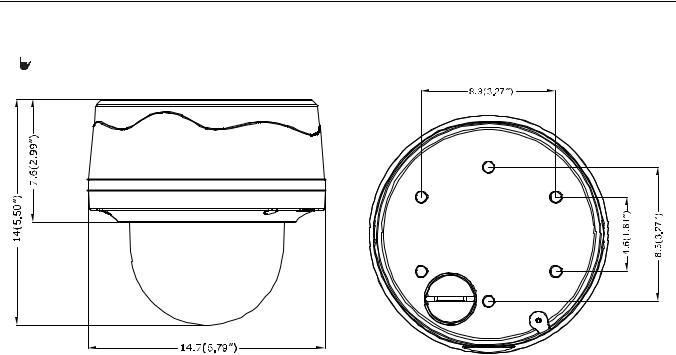
The dimension of the Sarix Professional Series Environmental Vandal Dome camera is depicted within the Figure 1-1 below.
 VALUES IN PARENTHESES ARE INCHES; ALL OTHERS ARE CENTIMETERS.
ENVIRONMENTAL VANDAL DOME
FIGURE 1-1: PHYSICAL DIMENSIONS
6

1.2 Models Introduction
The physical appearances and installation methods for the models indicated within the list below are similar. Consequently, please regard this manual where we use the example from IMP521-1RS as a reference to apply to all the varied models.
Model |
Description |
|
|
IMP121-1ES |
1MP Environmental Vandal Dome with Vari-focal lens |
|
|
IMP121-1RS |
1MP Environmental Vandal Dome with IR and Vari-focal lens |
|
|
IMP221-1ES |
2MP Environmental Vandal Dome with Vari-focal lens |
|
|
IMP221-1RS |
2MP Environmental Vandal Dome with IR and Vari-focal lens |
|
|
IMP321-1ES |
3MP Environmental Vandal Dome with Vari-focal lens |
|
|
IMP321-1RS |
3MP Environmental Vandal Dome with IR and Vari-focal lens |
|
|
IMP521-1ES |
5MP Environmental Vandal Dome with Vari-focal lens |
|
|
IMP521-1RS |
5MP Environmental Vandal Dome with IR and Vari-focal lens |
|
|
|
TABLE 1-1: MODELS LIST |
7

1.3 Physical Characteristics
|
1 |
|
2 |
|
3 |
4 |
8 |
5
9
10
6
7
FIGURE 1-2: CAMERA CONNECTIONS AND FEATURES 1/4 |
FIGURE 1-3: CAMERA CONNECTIONS AND FEATURES 2/4 |
11 12 13
17
14 |
15 |
16 |
|
|
FIGURE 1-4: CAMERA CONNECTIONS AND FEATURES 3/4 |
FIGURE 1-5: CAMERA CONNECTIONS AND FEATURES 4/4 |
1.Lower Case: The bottom case of the camera.
2.Lens Base: The physical main body of the camera.
3.Torx Screws of Lens Base * 3: The screws for fixing lens base with lower case.
4.Inner Liner: The inner adjustable liner to cover and beautify camera lens assembly.
5.IR Board: The IR LED embedded board for illumination under low-light environment.
6.Torx Screws of Top Cover * 3: The screws for fixing top cover with lens base.
8
7.Top Cover: The top cover of the camera.
8.Fool-proofing Design: The design is as a smart isolation to enable/disable auto defog function.
9.Micro SD Card Slot: The slot is for inserting extra micro SD card for file storage.
10.Default & Reset Button:
Default: Press the button for 6 seconds to restore the camera’s settings back to the factory default.
Reset: Press the button for below 1 second to reboot the camera.
11.Bottom Conduit Hole: The bottom hole for cable entry.
12.Side Conduit Hole: The side hole for cable entry.
13.Safety Wire Cord: The cord designed to connect with safety wire for additional suspension.
14.Digital I/O Connectors:
Audio In: Via “Au/I” and “GND” ports, connect to external device like microphone that receives sound for camera.
Audio Out: Via “Au/O” and “GND” ports, connect to device like speaker to be triggered through alarm output signals.
Alarm Out: Via “COM” and “AO” ports, connect to external device to be triggered through alarm output signals.
Alarm In: Via “GND” and “AI” ports, connect to external device that can trigger alarm input signals.
15.Power Terminal: The port is to connect with external either DC 12V or AC 24V power supply.
16.RJ-45 Network Port: Connect the RJ-45 connector to this port with a PoE+ (Class 4) compatible network device that supplies power through the Ethernet cable.
17.LED Indicators:
Green LED: With solid green, the LED indicates a live connection is established.
Orange LED: With flashing orange, the LED indicates data is being transmitted / received between camera and Internet.
9

2. Installation and Connection
2.1 Unpacking Everything
Check all items in the product box against the order form and the packing slip. In addition to this manual, the items below are included in the product box:
Environmental Vandal Dome camera * 1
Plastic Anchor * 4
Flat Head Screw (Tapping Type) * 4
Security Torx Wrench * 1
Mounting Template * 2
Printed quick installation guide * 1
Resource sheet * 1
Terminal Block * 1
Conduit Hole Plug * 1
Important Safety Instruction * 1
Anti-Seize lubricant (only necessary with pendant version, not supplied)
Please contact your dealer if any items are missing.
2.2 Optional Accessories
IMPICM-1ER: In-ceiling wall mount, for use with the environmental models
IMPPM-1ER: Pendant adapter, for use with the environmental models
2.3 Installation
Following tools might help you complete the installation:
A drill
Screwdrivers
Wire cutters
2.3.1 Checking Appearance
Although the protective materials used for the packaging should be able to protect the unit from most accidents during transportation, check the unit and its accessories for any visible damage. Remove the protective film to check items in accordance with the list in 2.1 Unpacking Everything.
10
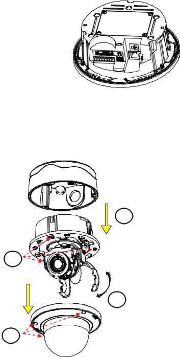
2.3.2 Disassembling the Camera
Please refer to the steps in the figure below for correct disassembling order.
1.Loosen the 3 camera top cover screws.
2.Gently pull the top cover downward to take it apart from the camera body.
3.Further loosen the 3 camera lens base screws.
4.Gently lift the camera lens base off from the lower case.
4
2 |
3 |
1
FIGURE 2 - 1: DISASSEMBLING THE CAMERA
11
2.3.3 Connecting the Wires
After disassembling, the I/O interfaces will be seen on the rear of the lens base.
Connect the power cable to the power port via one of the following 3 alternatives.
AC 24V: Connect a power cable that supplies AC24V power source to the power terminal.
DC 12V: Connect a power cable that supplies DC12V power source to the power terminal.
PoE+ (Class 4): Connect an Ethernet cable terminated with RJ-45 connector to the PoE+ RJ-45 port for both power supply and network connectivity purposes simultaneously.
Insert audio in/out cables and alarm in/out cables to the corresponding terminals of the camera if required.
FIGURE 2 - 2: REAR SIDE FOR WIRING CONNECTION
2.3.4 Mounting the Camera
Step 1. Preparation by Disassembling
Remove the camera housing, inner liner and bottom case.
4
3
2
1.Loosen the 3 top cover screws by torx wrench (supplied) followed by removing the top cover.
2.Lift to open the inner liner.
3.Loosen another 3 screws of camera lens base via torx wrench (supplied).
4.Remove the lens base from the lower case.
1
FIGURE 2 - 3: DISASSEMBLING THE CAMERA
12
Step 2. Mark Mounting Area
Use the guide pattern to prepare a mounting area for In-Ceiling Flush Mount.
1.Attach the mounting template on a desired mounting surface (normally for in-ceiling).
2.Drill a round hole ( 198mm) based on the template on the surface to have the camera embedded within the hole later.
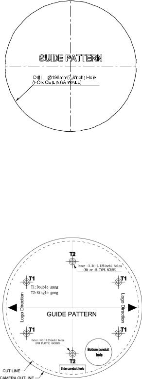
FIGURE 2 - 4: MOUNTING TEMPLATE FOR FLUSH MOUNT
Use the mounting template to prepare a mounting area for Surface Mount.
1.Place the supplied mounting template on a mounting surface. Drill 6 mm (0.2”) outer holes at the T1 or T2 template positions on the mounting surface. Then insert 4 or 2 supplied plastic anchors into the holes. (T1: for single-gang socket, T2: for double-gang socket, if applicable on mounting surface)
2.If you want to feed wiring from the hole on the top of the lower case, create a circular opening corresponding to the “Bottom conduit hole” of mounting template on the mounting surface.
3.If feeding wiring from the side of the lower case, you don’t need to drill a hole on the mounting surface. The “Side conduit hole” indication on the mounting template is for user to identify while mounting.
FIGURE 2 - 5: MOUNTING TEMPLATE FOR SURFACE MOUNT
13
Step 3. Mounting Schemes
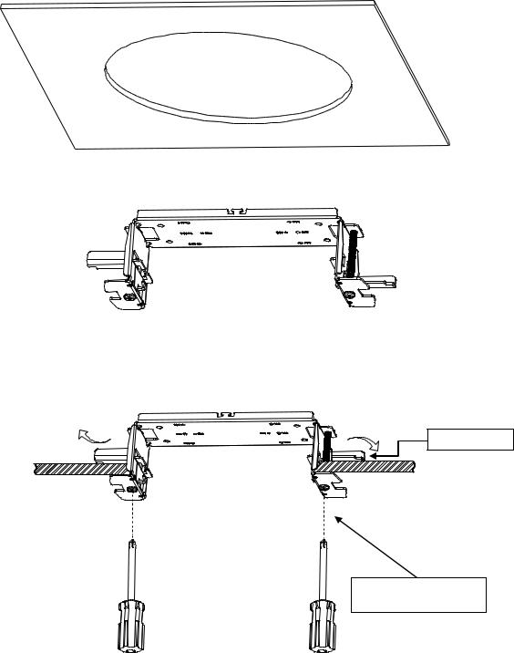
Method 1: Flush Mount (In-Ceiling)
1.Embed the in-ceiling mount bracket into the hole that was drilled based on the mounting template.
FIGURE 2 - 6: FLUSH MOUNT
2.Use a cross screw driver to turn the 2 bracket screws clockwise to extend the locking arms and tighten them securely to compress the locking arms so that the bracket can be fixed within the in-ceiling area firmly.
Locking Arms
Tighten the screws to extend the locking arms
FIGURE 2 - 7: FLUSH MOUNT
14
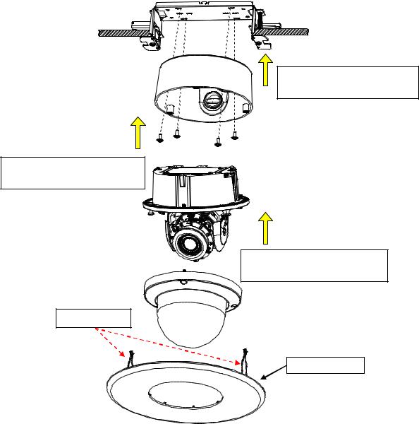
3.Based on your needs, use the bottom conduit hole or side conduit hole on the lower case for cable entry and connect the required cables.
NOTE: Please properly lock the conduit hole plug on the unused hole. For example, lock the side conduit hole with the plug while using the bottom conduit hole for cable entry and vice versa.
4.Fix the lower case onto the in-ceiling bracket by fastening the 4 screws followed by aligning the identifying red dots of lower case and lens base to properly assemble them together with securing the 3 lens base screws.
5.After adjusting focus position to the satisfied field of view, mount the top cover on the lens base, both of which have a red dot respectively also for aligning identification and tighten the 3 top cover screws firmly.
6.Attach the 2 spring hooks flanked the protective cover to the in-ceiling bracket for mounting completion.
Assemble lens base with lower case and fasten the 3 torx screws.
Fix lower case onto the in-ceiling bracket by securing the 4 screws.
Further mount top cover onto lens base and tighten the 3 torx screws.
Spring Hook * 2
Protective Cover
FIGURE 2 - 8: SURFACE MOUNT
NOTE: It is strongly recommended that you first ensure the mounting area is stable enough to withstand the in-ceiling bracket and locking arms clamping on the ground of safety concern.
15
Method 2: Surface Mount
After cable entry and wiring, align the red dots of lower case and lens base followed by securing the torx screws tightly.
After adjusting focus angle, align the red dots of lens base and top cover followed by fastening the torx screws to complete the procedure.
FIGURE 2 - 9: SURFACE MOUNT
1.Based on your needs, use the bottom or side conduit hole on the lower case for cable entry and connect the required cables first. Then mount the lower case on a surface by securing screws (supplied) into the inserted plastic anchors tightly.
2.Align the lower case and the lens base, both of which have a red dot on the top side respectively for aligning identification. Use the red dots to properly align them and then securely fasten the 3 screws of the lens base to the bottom case with torx key (supplied).
3.Adjust the focusing position by rotating, panning and tilting the camera lens base. When rotating the camera lens, do not rotate it over the stop point.
4.Fit the inner liner over the camera lens base until it snaps into the place.
5.Mount the top cover on the lens base, both of which similarly have a red dot for aligning identification. Be aware that the red dot of top cover is within interior instead of top side.
6.Use the torx wrench (supplied) to tighten the 3 top cover screws to complete mounting.
NOTE: Please properly lock the conduit hole plug on the unused hole. For example, lock the side conduit hole with the plug while using the bottom conduit hole for cable entry and vice versa.
16
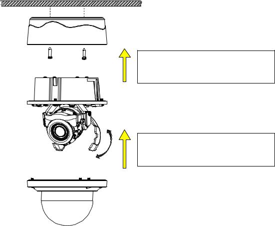
Method 3: Pendant Mount (requires pendant adapter mounting accessory)
NOTE: Mounts and conduits must be sealed to prevent condensation in the camera
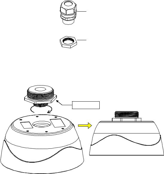
The Pendant Installation involves mounting the camera to the wall with IMPPM-1ER Sarix Environmental Pendant Mount for Environmental Vandal Dome. The camera must be installed in the back box with a 3/4” rain-tight compression gland (#1) and a lock nut (#2) as shown below. The compression gland and lock nut are not provided.
Rain-tight Compression
Gland
Lock Nut
FIGURE 2-10: RAIN-TIGHT& LOCK NUT
1.Rotate the adaptor ring, which can connect with 1 1/2” pole later, clockwise to the pendant mount back box securely as shown below. The diagram in the right side is the back box mounted with the adaptor ring.
Adaptor Ring
FIGURE 2 -11: PENDANT MOUNT 1/2
NOTE: Anti-seize compound should be applied on environmental pendant. Not doing so might prevent the unit from being separated in the future. Waterproof tape can also be used to help prevent water ingress damage.
17
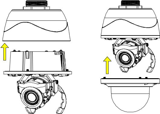
2.Attach the lens base to the pendant mount back box after wires connection and securely fasten the 3 screws of the lens base by the torx wrench (supplied). Finally, assemble the top cover with the lens base, which is already attached to the back box, followed by fastening the 3 screws of top cover to complete the installation.
FIGURE 2 -12: PENDANT MOUNT 2/2
18
If you possess a safety wire (sold separately), connect the safety wire with one end to the mounting surface and the other end to the safety-cord screw of the camera. Depending on different applications, please connect the safety wire to the corresponding safety-cord screw as shown in the following figures.
Safety-cord screw |
Safety-cord screw |
FIGURE 2 -13: SAFETY-CORD SCREW
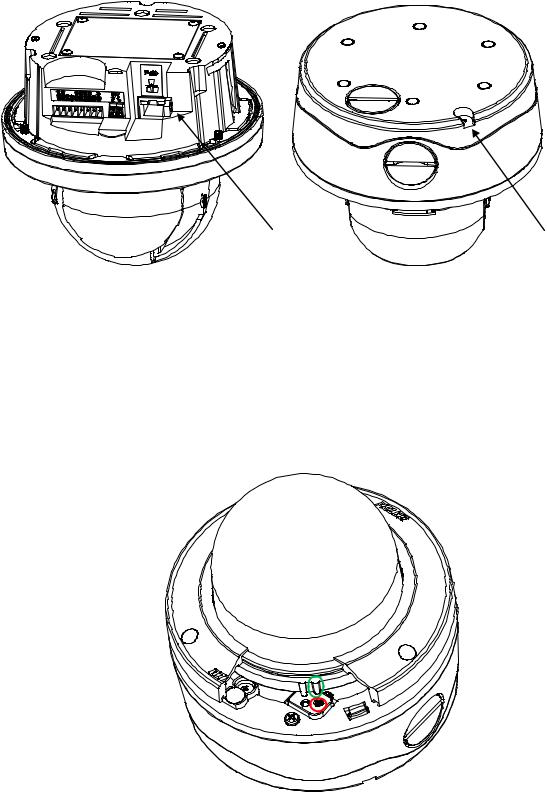
2.3.5 Top Cover Defog
Defog function, which heats up camera to overcome certain extreme weather conditions (e.g., snow or frost), which may harm the operation of camera, is embedded within this vandal camera. However, in order to prevent scald incident from happening to installers, the Defog heating function won’t be activated when the top cover is detached from the camera body as the shown in the following figure where a button at the camera body (marked red) is not pressed by the salient point of top cover (marked green). Instead, when the salient point presses the button of camera body, the heating function will activate automatically.
FIGURE 2 -14: TOP COVER DEFOG ACTIVATION
19
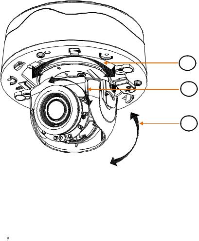
2.3.6 Adjusting the Camera Position
The camera has three axes for adjusting field of view on different applications. While screening live view on your monitor, adjust the position by procedures below simultaneously for desired focusing position.
Pan Adjustment (A)
Rotate the lens base until you are satisfied with the field of view. Note that the side conduit hole of lower case is the point where the camera lens shouldn’t be rotated over.
Horizontal Rotation (B)
Rotate 3D assembly in the lens base, but do not turn assembly more than 355° as this may have the internal cables twisted, disconnected, or broken.
Tilt Adjustment (C)
Lift to open the inner liner, and tilt the camera lens to your desired angle. Restore the inner liner back to its default position after adjustment.
NOTE: Limitation for three axes position: Pan range: ±177°, Rotate range: ±177°, Tilt range: 35° 90°
A
B
C
FIGURE 2 -15: ADJUSTING THE CAMERA POSITION
2.3.7 Adjusting the Focus
1.View the camera image using the browser (refer to 2.4 Connection on page 23).
2.Use the settings in the Web interface (refer to 3.2.3.4 Focus on page 46) to adjust the zoom and focus of the lens to the desired field of view.
3.Also the focus can be adjusted b moving the zoom slider and using the Focus options in the live webpage.
NOTE: Focus adjustment is done exclusively with Web UI.
20
2.3.8 Network Topology
The unit, which is equipped with Ethernet RJ-45 network interface, can deliver video images in real time via either Internet or Intranet. Please refer to the skeleton drawings shown below to aid your understanding.
FIGURE 2-16: NETWORK TOPOLOGY
21
 Loading...