


 Loading...
Pelco IMM12036-EBASUS, IMM12036-E-BASE, IMM12036-BASE, IMM12036-B1SUS, IMM12036-B1S User Manual
...Optera IMM Installation
Parts List
All Models
Camera |
Lower Dome |
Documentation |
2 Mac Address T20 Bit |
8-Pin Connector |
|
|
|
Labels |
|
|
|
|
||
In-Ceiling Models |
Surface Mounts Models |
Pendant Models |
||
Back Box |
Mounting Plate |
Surface Mount |
Pendant Mount |
Anti-Seize Lubricant |
Unsupplied Parts
All Models
•Pipe/conduit (if applicable)
•Conduit adapters (if applicable)
•Cat5 (or higher) cable, appropriately terminated for POE+
•24 AWG, 8-wire multiconductor cable (if using alarm, relays, and/or audio)
•SD card, 32GB SanDisk Extreme® PLUS microSDHC™ UHS-I
Surface Mount Models
1 of the following mounting substrates and fasteners:
•Standard 4 in. square electrical box and appropriate fasteners
•Standard 2-gang electrical box and appropriate fasteners
•Any substrate using 3 standard screws, size M6 or 1/4 in.
Pendant Models
WMVE-SR Wall Mount (if using the wall mount for environmental and vandal-resistant models)
WMVE-SW Wall Mount (if using the wall mount for indoor models)
INSTALLATION MANUAL
C2283M | 9/15

Product Overview
NOTICE: Pelco recommends installing the camera at a height of 3 meters (10 feet) or higher for best results. To ensure an unobstructed view, the expected field of view should be at least 4 meters (12 feet) away from the camera.
R
- |
+ |
- |
+ |
-A |
+ |
-R |
+ |
R |
Panomersive |
||
with |
Sure |
Vision |
|
||
PoE+
To ensure reliable local storage, Pelco recommends using a new 32 GB SanDisk Extreme® PLUS microSDHC™ UHS-I card. If the card has been used or reformatted, local storage may not function properly.
RUsing a small tool, like a paper clip, press once to restart the camera. Press and hold for 10 seconds to restore the camera to factory settings.
•Flashes green: cycling power.
•Solid Green: power is active.
•Flashes green: network activity
•Solid amber: 1000 Mbps network connection
•Solid green: 100 Mbps network connection
•Red (solid or flashing): contact Pelco Product Support at 1-800-289-9100 (USA and Canada) or +1-559-292-1981 (international).
2
Wiring Information
|
|
|
|
|
|
|
|
|
|
|
|
|
|
|
|
|
|
|
|
|
|
|
|
|
|
|
|
|
|
|
|
|
|
|
|
|
|
|
|
|
|
|
|
|
|
|
|
|
|
|
|
|
|
|
|
|
|
|
|
|
|
|
|
|
|
|
|
|
|
|
|
|
|
|
|
|
|
|
|
|
|
|
|
|
|
|
|
|
|
|
|
|
|
|
|
|
|
|
|
|
|
|
|
|
|
|
|
|
|
|
|
|
|
|
|
|
|
|
|
|
|
|
PoE+ |
|
|
|
|
|
|
|
|
|
|
|
|
|
|
|
|
|
|
|
|
|
|
|
Pin |
|
Function |
Pin |
PoE+ Mode A |
PoE+ Mode B |
|||||||||||||||
|
|
|
|
|
|
|
|
|
|
|
|
|
|
|
|
|
|
|
|
|
1 |
|
|
|
|
|
|
|
|
Audio Out– |
1 |
TX+, PoE+ 1-2 |
TX+ |
||||||||
|
|
|
|
|
|
|
|
|
|
|
|
|
|
|
|
|
|
|
|
|
2 |
|
|
|
|
|
|
|
|
Audio Out+ |
2 |
TX–, PoE+ 1-2 |
TX– |
||||||||
|
|
|
|
|
|
|
|
|
|
|
|
|
|
|
|
|
|
|
|
|
3 |
|
|
|
|
|
|
|
|
Audio In– |
3 |
RX+, PoE+ 3-4 |
RX+ |
||||||||
|
|
|
|
|
|
|
|
|
|
|
|
|
|
|
|
|
|
|
|
|
4 |
|
|
|
|
|
|
|
|
Audio In+ |
4 |
Not used |
PoE+ 1-2 |
||||||||
|
|
|
|
|
|
|
|
|
|
|
|
|
|
|
|
|
|
|
|
|
5 |
|
|
|
|
|
|
|
|
Alarm Input |
5 |
Not used |
PoE+ 1-2 |
||||||||
|
|
|
|
|
|
|
|
|
|
|
|
|
|
|
|
|
|
|
|
|
6 |
|
|
|
|
|
|
|
|
Ground |
6 |
RX–, PoE+ 3-4 |
RX– |
||||||||
|
|
|
|
|
|
|
|
|
|
|
|
|
|
|
|
|
|
|
|
|
7 |
|
|
|
|
|
|
|
|
Relay N.O. |
7 |
Not used |
PoE+ 3-4 |
||||||||
|
|
|
|
|
|
|
|
|
|
|
|
|
|
|
|
|
|
|
|
|
8 |
|
|
|
|
|
|
|
|
Relay Return |
8 |
Not used |
PoE+ 3-4 |
||||||||
|
|
|
|
|
|
|
|
|
|
|
|
|
|
|
|
|
|
|
|
|
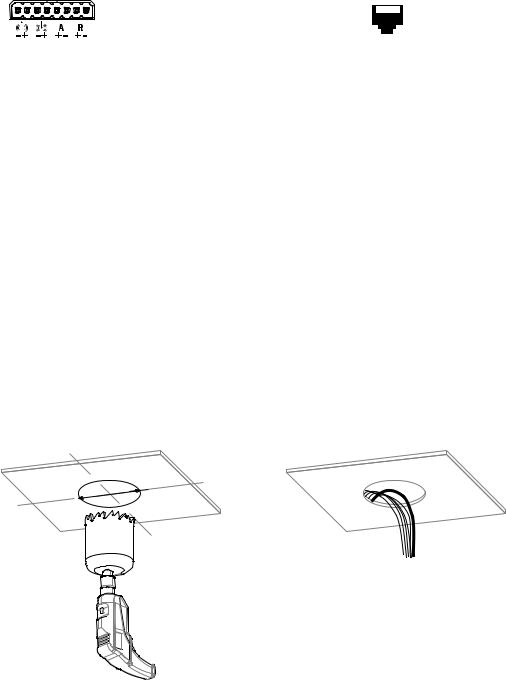
Installing the In-Ceiling Mount
1.
Ø 15.24 cm (6.00 in)
3

2.Remove either the conduit plug (side) or grommet (top) for side or top wire entry.
3.Prepare the wire entry holes. If using the supplied grommet (plenum rating is not required), set the grommet aside for use later. If using conduit (not supplied), replace with 25mm or 2/4 in. conduit adapters.
Installing the Back Box
1.Ensure that the support wings are rotated inward, and push the back box through the mounting hole.
2.Replace the other entry opening with the supplied conduit plug.
3.Tighten the two mounting screws to secure the back box using the supplied bit.
4.Feed the wires:
•If using conduit (not supplied): Feed wires through the conduit adapter, into the back box, and attach the conduit to the adapter.
•If using the grommet (supplied): Feed the wires into the back box; pass the unterminated cables through the grommet; and then insert the grommet.
5.Terminate the wires using an appropriate connector (not supplied).
4
Loading...