

Installation and Assembly:
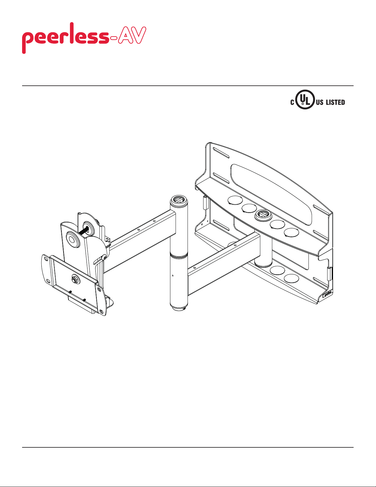
Articulating Swivel Arm for 37" - 60" Flat Panel Displays
Models: PLA60, PLA60-S, PLAV60, PLAV60-S
Max UL Load Capacity:
175 lb (79 kg)
2300 White Oak Circle • Aurora, Il 60502 • (800) 865-2112 • Fax: (800) 359-6500 • www.peerlessmounts.com
ISSUED: 05-02-06 SHEET #: 202-9112-4 06-01-11

Note: Read entire instruction sheet before you start installation and assembly.
WARNING
• Do not begin to install your Peerless product until you have read and understood the instructions and warnings
contained in this Installation Sheet. If you have any questions regarding any of the instructions or warnings, for US
customers please call Peerless customer care at 1-800-865-2112, for all international customers, please contact
your local distributor.
• This product should only be installed by someone of good mechanical aptitude, has experience with basic building
construction, and fully understands these instructions.
• Make sure that the supporting surface will safely support the combined load of the equipment and all attached
hardware and components.
• Never exceed the Maximum Load Capacity. See page one.
• If mounting to wood wall studs, make sure that mounting screws are anchored into the center of the studs. Use of
an "edge to edge" stud fi nder is highly recommended.
• Always use an assistant or mechanical lifting equipment to safely lift and position equipment.
• Tighten screws fi rmly, but do not overtighten. Overtightening can damage the items, greatly reducing their holding
power.
• This product is intended for indoor use only. Use of this product outdoors could lead to product failure and personal
injury.
• This product was designed to be installed on the following wall construction only;
WALL CONSTRUCTION HARDWARE REQUIRED
• Wood Stud Included
• Wood Beam Included
• Solid Concrete Included
• Cinder Block Included
• Metal Stud Do not attach except with Peerless Metal Stud Accessory Kit
(not evaluated by UL)
• Brick Contact Qualifi ed Professional (not evaluated by UL)
• Other or unsure? Contact Qualifi ed Professional
Tools Needed for Assembly
• stud fi nder ("edge to edge" stud fi nder is recommended)
• drill
• 3/16" (5mm) drill bit for wood studs
• 3/8" (10mm) masonry drill bit for concrete
• 7/16" socket wrench with extension (recommended)
• level
• phillips screwdriver
Accessories
• External Wall Plate (WSP716, WSP716-S, WSP724,
WSP724-S) (Metal Stud not evaluated by UL)
Table of Contents
Parts List............................................................................................................................................................................ 3, 4
Installation to Double Wood Stud Wall ...................................................................................................................................5
Installation to Solid Concrete or Cinder Block ........................................................................................................................6
2 of 10
ISSUED: 05-02-06 SHEET #: 202-9112-4 06-29-11
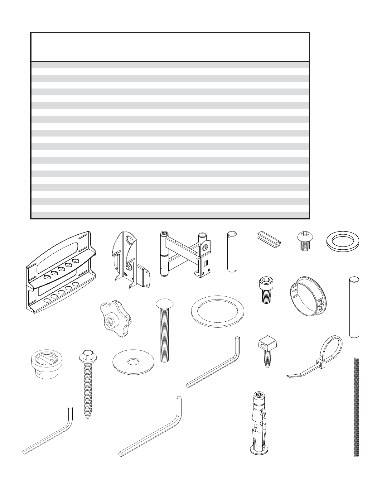
Before you start make sure all parts listed are included with your product.
A
py
V
Parts List
PLA60
Description Qty. Part # Part # Part # Part #
wall plate 1 201-1040 201-4040
tilt-roll assembly 1 201-1093 201-4093
B
arm assembly 1 201-1072 201-4072
C
wall support arm axle 1 201-1041 201-1041
D
vinyl trim 3 600-1012 600-1012
E
M10 x 1.5 x 15 mm screw bolt 8 520-9262 520-9262 520-9262
F
.505 x .75 x .062" nylon washer 1 540-1074 540-1074
G
tilt adjustment knob 1 560-0108 560-0108
H
carriage bolt 3/8"-16 x 3.25" 1
I
1.525 x 2 x .062" delrin washer 2
J
#8-32 x .375" socket head cap screw 1
K
plastic finishing cap 8
L
holding pin 1
M
retainer plug 1
N
5/16 x 3" wood screw 8
O
.250 x 1 x .068" washer 8
P
9/64" allen wrench 1
Q
cable management clips 4 590-1166 590-1166 590-1166 590-1166
R
cable tie 4 590-1168 590-1168 590-1168 590-1168
S
36" polyester mesh sleeve 1 600-1015 600-1015 600-1015 600-1015
T
6 mm allen wrench 1 560-9716 560-9716 560-9716 560-9716
U
10 mm allen wrench 1 n/a n/a 560-9727 560-9727
W concrete anchor 8 590-0321 590-0321
Some parts may appear slightly different than illustrated.
520-1315 520-1315
540-1070 540-1070
520-1210 520-1210
590-1123 590-1123
580-1166 580-1166
590-1007 590-1007
520-1243 520-1243
540-1063 540-1063
560-9728 560-9728
PLA60-S PLAV60 PLAV60-S
201-1040 201-4040
201-1048 201-4048
201-1049 201-4049
201-1041 201-1041
600-1012 600-1012
520-9262
540-1074 540-1074
560-0108 560-0108
520-1315 520-1315
540-1070 540-1070
520-1210 520-1210
590-1123 590-1123
580-1166 580-1166
590-1007 590-1007
520-1243 520-1243
540-1063 540-1063
560-9728 560-9728
590-0321
590-0321
N
U
O
H
B
P
CAEF
I
J
D
K M
L
G
R
S
Q
W
T
V
3 of 10
ISSUED: 05-02-06 SHEET #: 202-9112-4 06-29-11

Installation to Wood Stud Wall
WARNING
• Installer must verify that the supporting surface will safely support the combined load of the equipment and all
attached hardware and components.
• Tighten wood screws so that wall plate is fi rmly attached, but do not overtighten. Overtightening can damage the
screws, greatly reducing their holding power.
• Never tighten in excess of 80 in. • lb (9 N.M.).
• Do not attach directly to a metal stud wall. Use of a triple stud WSP wall plate is required for attachment to metal
studs (contact customer care). Metal stud installation is not UL evaluated.
• Make sure that mounting screws are anchored into the center of the stud. The use of an "edge to edge" stud fi nder
is highly recommended.
• Hardware provided is for attachment of mount through standard thickness drywall or plaster into wood studs. Installers are responsible to provide hardware for other types of mounting situations (not evaluated by UL).
• Never exceed the Maximum UL Load Capacity of 175 lb (79 kg).
Wall plate (A) can be mounted to two studs that are 16" apart. Use a stud fi nder to locate the edges of the
1
studs. Use of an edge-to-edge stud fi nder is highly recommended. Based on their edges, draw a vertical line
down each stud’s center. Place wall plate on wall as a template. The top mounting slots should be located .36"
above the desired screen center for PLA60 and PLA60-S and .43" below the desired screen center for PLAV60
and PLAV60-S. Level plate, and mark the center of the eight mounting holes. Make sure that the mounting
holes are on the stud centerlines. Drill eight 7/32" dia. holes 3" deep. Make sure that the wall plate is level,
secure it using eight 5/16 x 3" wood screws (O) and washers (P).
Skip to step 2 on page 6.
WARNING
• Never mount this product to metal studs without the
required accessory.
P
O
4 of 10
A
ISSUED: 05-02-06 SHEET #: 202-9112-4 06-29-11

Installation to Solid Concrete or Cinder Block Wall
WARNING
• When installing Peerless wall mounts on cinder block, verify that you have a minimum of 1-3/8" (35mm) of actual
concrete thickness in the hole to be used for the concrete anchors. Do not drill into mortar joints! Be sure to mount
in a solid part of the block, generally 1" (25mm) minimum from the side of the block. Cinder block must meet ASTM
C-90 specifi cations. It is suggested that a standard electric drill on slow setting is used to drill the hole instead of a
hammer drill to avoid breaking out the back of the hole when entering a void or cavity.
• Concrete must be 2000 psi density minimum. Lighter density concrete may not hold concrete anchor.
• Make sure that the supporting surface will safely support the combined load of the equipment and all attached hardware and components.
Use wall plate (A), making sure that it is level, as
1
a template to mark holes. The top mounting slots
should be located at your desired display center. Use
the masonry bit to drill 3/8" (10mm) dia. holes to a
minimum depth of 3" (76mm). Insert anchors (W) in
holes fl ush with wall as shown (right). Place wall plate
(A) over anchors (W) and secure with 5/16 x 3" wood
screws (O) and washers (P).
WARNING
• Tighten screws so that wall plate is fi rmly attached,
but do not overtighten. Overtightening can damage
screws, greatly reducing their holding power.
• Never tighten in excess of 80 in. • lb (9 N.M.).
• Always attach concrete expansion anchors directly
to load-bearing concrete.
• Never attach concrete expansion anchors to
concrete covered with plaster, drywall, or other
fi nishing material. If mounting to concrete surfaces
covered with a fi nishing surface is unavoidable (not
evaluated by UL), the fi nishing surface must be
counterbored as shown below. Be sure concrete
anchors do not pull away from concrete when
tightening screws. If plaster/drywall is thicker than
5/8" (16mm), custom fasteners must be supplied by
installer (not evaluated by UL).
1
Drill holes and insert anchors (W).
2
A
O
Place plate (A) over anchors (W) and secure with screws (O).
3
Tighten all fasteners.
W
P
concrete
surface
W
W
plate
CUTAWAY VIEW
wall
plaster/
dry wall
INCORRECT CORRECT
concrete
wall
plate
plaster/
dry wall
concrete
5 of 10
O
A
ISSUED: 05-02-06 SHEET #: 202-9112-4 06-29-11

WARNING
• If you are uncertain that product is properly installed, call customer care.
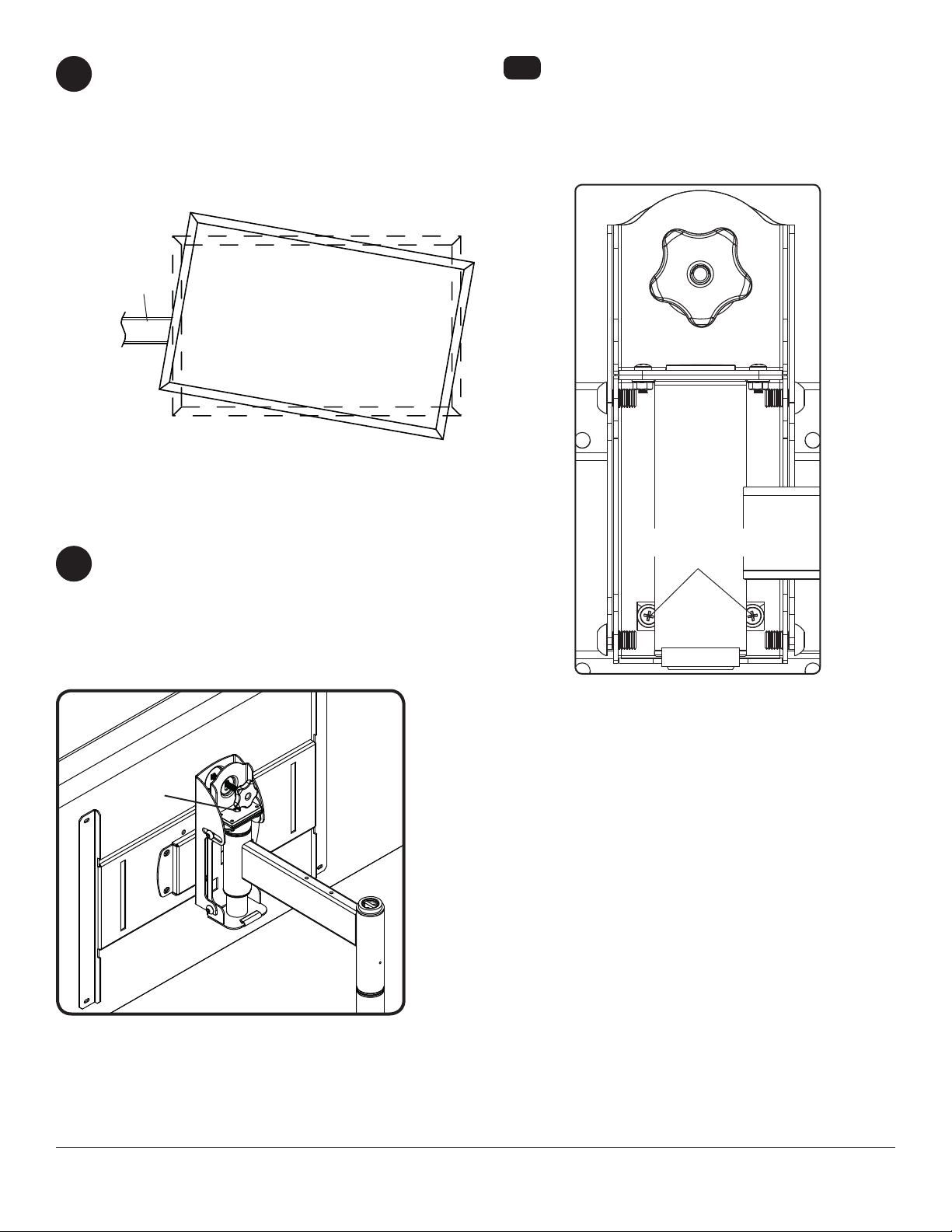
Note: There are fi ve mounting positions. The
2
center position is shown (right). Slide washer
(J) over wall support arm axle (D). Next, insert
plastic cap (N) into axle. Then, insert holding pin
(M) into axle. See detail 1.
Place arm assembly (C) with washer (J) into wall
2-1
plate (A). Insert axle assembly shown in detail
1 through wall plate (A), arm assembly (C), and
washer (J). Lock axle in place by aligning holding
pin (M) with notches shown in detail 2.
Insert socket cap screw (K) into hole at bottom
2-2
of wall support arm axle (D) as shown in detail 3.
Tighten screw using 9/64" allen wrench (Q).
Note: Fit of axle (D) into wall plate (A) and arm
assembly (C) will be tight. Gently tap into place
with a hammer if necessary.
C
N
J
D
M
DETAIL 1
A
NOTCH
DETAIL 2
J
K
D
DETAIL 3
Snap four cable management clips (R) into top or bottom of arm assembly (C) as shown. Cable ties (S) are
3
used with clips for cord management.
Slide one mesh sleeve (T) over each cable. Use cable ties (S) to tighten mesh sleeves to cables.
3-1
T
R
C
S
6 of 10
ISSUED: 05-02-06 SHEET #: 202-9112-4 06-29-11

Attach two pieces of vinyl trim (E) to wall plate (A). Next, attach one piece of vinyl trim to bottom of swivel box on
4
arm assembly (C).
Insert one fi nishing cap (L) into each unused hole of wall plate (A).
4-1
L
SWIVEL BOX
A
C
E
Note: Refer to adapter bracket instruction sheet for attachment of adapter bracket to plasma before proceeding
with step 5. If your adapter bracket has an aluminum race attached to it, remove before proceeding and discard race. It
is not used with this product.
Insert and tape carriage bolt (I) into top hole of pitch-roll assembly (B). Attach tilt-roll assembly to adapter
5
bracket with four M10 socket screws (F). Tighten screws using 6 mm allen wrench (U).
Note: Adapter bracket (not UL evaluated, sold separately) will vary in size and style.
CAUTION
• Do not overtighten screws! Overtightening may hinder roll option.
B
F
GENERIC
ADAPTER BRACKET
I
7 of 10
ISSUED: 05-02-06 SHEET #: 202-9112-4 06-29-11

WARNING
• Use an assistant or mechanical lifting equipment to safely lift and position the plasma TV.
Insert two M10 screws (F) into swivel box on arm assembly (C) as shown. Leave approx. 1/4" of exposed
6
thread.
SWIVEL BOX
Hook tilt-roll assembly (B) onto M10 screws (F).
6-1
Insert carriage bolt (I) into slot of swivel box as
shown in fi gure 6.1. Install nylon washer (G) and tilt
adjustment knob (H).
Install remaining two M10 screws (F) as shown in
6-2
fi gure 6.2. HAND TIGHTEN all four M10 screws to
allow for tilt adjustment. Remove tape from carriage
bolt (I). For tilt adjustment, push back on the top of
plasma to relieve pressure on knob. Adjust tilt to desired position and tighten tilt adjustment knob (H),
then securely tighten all four M10 screws (F) using
6 mm allen wrench (U).
C
F
.25"
CAUTION
• After tilt is adjusted, all fasteners must be tightened.
Failure to do so will result in damage to the mount.
SWIVEL BOX
H
G
H
I
I
F
F
B
Adapter bracket not shown for clarity. Adapter bracket not shown for clarity.
fi g. 6.1 fi g. 6.2
8 of 10
ISSUED: 05-02-06 SHEET #: 202-9112-4 06-29-11
Depending on the specifi c size & weight of the plas-
7
ma, articulating swing arm may be angled at different
positions, causing plasma to appear to lean sideways
at different articulating positions. Tilt-roll assembly (B)
allows plasma to be manually adjusted, so plasma
can be horizontal at all positions. To adjust, gently
rotate plasma by hand to desired position.
ARTICULATING
ARM
PLASMA
If it is too diffi cult to adjust roll of plasma, loosen
7-1
screws shown in fi gure 7.1 using a phillips screwdriver.
IMPORTANT! Do not loosen or tighten screws
more than 1/8 turn.
FOR PLAV 60 ONLY:
Position of screen may be adjusted vertically up to
8
.79" in each direction by doing the following:
• To lower screen, turn socket screw shown in fi gure
8.1 clockwise with 10 mm allen wrench (V).
• To raise screen, turn socket screw shown in fi gure
8.1 counterclockwise with 10 mm allen wrench (V).
SOCKET
SCREW
ROLL
ADJUSTMENT
SCREWS
fi g. 7.1
fi g 8.1
9 of 10
All other brand and product names are trademarks or registered trademarks of their respective owners.
ISSUED: 05-02-06 SHEET #: 202-9112-4 06-29-11
© 2011, Peerless Industries, Inc. All rights reserved.

LIMITED FIVE-YEAR WARRANTY
Peerless Industries, Inc. (“Peerless”) warrants to original end-users of Peerless® products will be free from defects in material and workmanship, under normal
use, for a period of fi ve years from the date of purchase by the original end-user (but in no case longer than six years after the date of the product’s manufacture).
In no event shall the duration of any implied warranty of merchantability or fi tness for a particular purpose be longer than the period of the applicable
express warranty set forth above. Some states do not allow limitations on how long an implied warranty lasts, so the above limitation may not apply to you.
This warranty does not cover damage caused by (a) service or repairs by the customer or a person who is not authorized for such service or repairs by Peerless,
(b) the failure to utilize proper packing when returning the product, (c) incorrect installation or the failure to follow Peerless’ instructions or warnings when installing,
In no event shall Peerless be liable for incidental or consequential damages or damages arising from the theft of any product, whether or not secured
by a security device which may be included with the Peerless® product. Some states do not allow the exclusion or limitation of incidental or consequential
This warranty is in lieu of all other warranties, expressed or implied, and is the sole remedy with respect to product defects. No dealer, distributor, installer or other
person is authorized to modify or extend this Limited Warranty or impose any obligation on Peerless in connection with the sale of any Peerless® product.
At its option, Peerless will repair or replace, or refund the purchase price of, any product which fails to conform with this warranty.
using or storing the product, or (d) misuse or accident, in transit or otherwise, including in cases of third party actions and force majeure.
damages, so the above limitation or exclusion may not apply to you.
This warranty gives specifi c legal rights, and you may also have other rights which vary from state to state.
www.peerlessmounts.com
© 2011 Peerless Industries, Inc.
10 of 10
ISSUED: 05-02-06 SHEET #: 202-9112-4 06-29-11
 Loading...