

Page 1
Installation and Assembly
Flat-Panel Base Lock-Down Kit For Philips Display
Models
Models: HLG452-002, HLG452-002-Q10
Maximum Display Weight: 100 lb (45.35 kg)
3215 W. North Ave. • Melrose Park, IL 60160 • (800) 729-0307 or (708) 865-8870 • Fax: (708) 865-2941 • www.peerlessmounts.com
ISSUED: 09-04-08 SHEET #: 090-9150-3 10-05-09
Page 2
NOTE: Read instruction sheet before you start installation and assembly .
Parts may appear slightly different than illustrated.
Before you begin, make sure all parts shown are included
with your product.
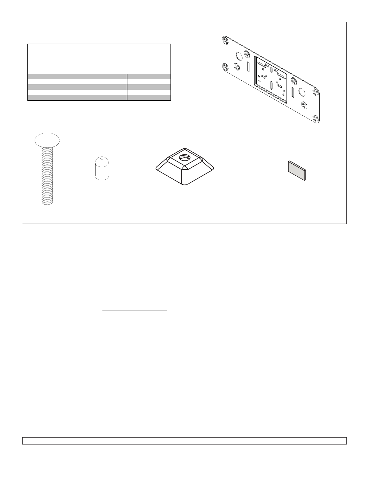
Parts List
Description
A lock-down plate 1 090-1757 10 090-1757
B 1/4-20 x 1 3/4" carriage bolt 2 520-1017 20 520-1017
C plastic cap 2 590-1294 20 590-1294
D 1/4-20 slope nut 3 530-0035 30 530-0035
E adhesive strip 4 570-0017 40 570-0017
B
Qty. Part # Qty. Part #
C
HLG452-002-Q10HLG452-002
A
E
D
Tools Needed for Assembly
• drill
• 1/4" drill bit
• 5/8" open box wrench
• phillips screwdriver
• 5/32 allen wench
• 3M™ Rubber & Vinyl 80 S pray Adhesive (generic
name: Contact 80 Neoprene Vinyl S pray Adhesive)
This product can be found at hardware and craft stores,
as well as on the 3M website: http://solutions.3m.com/.
Accessory
• ACC939 - 1/4-20 x 2.25" carriage screws for thicker
desktop surfaces
• MIS660 - Neck Security Screws for 26HFL5830D/27,
32HFL5460D/27, 32HFL5860D/27, 32HF7965D/27,
37HFL5560D/27, 42HFL5860D/27, 42HFL7580A/27,
52HFL5580D/27
•ACC943: Installation T emplate (plate only)
Installation Option 1 (Fasteners) Pages 3 and 4
Installation Option 2 (Adhesive Strips) Pages 5 and 6
2 of 6
Visit the Peerless Web Site at www.peerlessmounts.com For customer care call 1-800-729-0307 or 708-865-8870.
ISSUED: 09-04-08 SHEET #: 090-9150-3 10-05-09
Page 3

Installation Option 1 (Fasteners)
DISPLAY MODEL HOLE PATTERNS
SBP240M/27
A.
SCREWS SUPPLIED BY DISPLA Y
MANUFACTURER
42HF7945D/27
B.
37HFL5560D/27
42HFL55860D/27
42HFL7945D/27
42HFL7580A/27
52HFL5580D/27
26HFL5830D/27
C.
32HFL5460D/27
32HFL5860D/27
32HFL7560D/27
32HF7965D/27
32HFL7965D/27
SCREWS SUPPLIED BY DISPLA Y
MANUFACTURER
Use lock-down plate (A) as a template to mark location
1
of holes, point 1 and point 2, approximately 7" apart on
table. Drill two holes using a 1/4'' drill bit.
7"
(178 mm)
POINT 1
POINT 2
SCREWS SUPPLIED BY DISPLA Y
MANUFACTURER
Slide two 1/4-20 x 1 3/4" bolts (B) through slots as
2
shown below.
NOTE: 2 1/4" carriage bolts (ACC939) are available
for use with thicker mounting surfaces.
B
A
TABLE T OP
3 of 6
Visit the Peerless Web Site at www.peerlessmounts.com For customer care call 1-800-729-0307 or 708-865-8870.
ISSUED: 09-04-08 SHEET #: 090-9150-3 10-05-09
Page 4

Attach lock-down plate to display base bottom using
3
screws provided by manufacturer. Refer to page three
for lock-down plate/ display base stand hole pattern.
NOTE: Remove existing rubber feet from display base
that interfere with the lock-down plate.
DISPLA Y BASE ST AND
RUBBER FEET
Hand tighten slope nut (D) through 1/4-20 x 1 3/4"
4
screw bolt (B) until snug against bottom of desktop
surface. Thread another slope nut (D) upside-down,
about two turns from first slope nut (D). Insert a open
box wrench between both slope nuts (D) and tighten.
NOTE: Avoid jamming both slope nuts (D) together,
doing so may make it difficult to remove slope nut
used for tightening first slope nut (D). Af ter slope nut is
secure remove bottom slope nut and add plastic cap
(C) as shown in figure 4.2. Repeat with remaining
1/4-20 x 1 3/4" screw bolt (B).
BOTTOM OF DESKTOP
SCREWS SUPPLIED BY
MANUFACTURER
NOTE: Display base stand and mounting
hole locations may appear different than
illustrated.
A
D
B
TIGHTENING
SLOPE NUT
FIG 4.1
B
C
FIG 4.2
4 of 6
Visit the Peerless Web Site at www.peerlessmounts.com For customer care call 1-800-729-0307 or 708-865-8870.
ISSUED: 09-04-08 SHEET #: 090-9150-3 10-05-09
Page 5

Installation Option 2 (Adhesive Strips)
DISPLAY MODEL HOLE PATTERNS
SBP240M/27
A.
SCREWS SUPPLIED BY DISPLA Y
MANUFACTURER
42HF7945D/27
B.
37HFL5560D/27
42HFL55860D/27
42HFL7945D/27
42HFL7580A/27
52HFL5580D/27
Attach lock-down plate to display base bottom using
screws provided by manufacturer. Refer to lock-down
plate/ display base stand hole pattern.
NOTE: Remove existing rubber feet from display base
that interfere with the lock-down plate.
42HF7945D/27
RUBBER FEET
SCREWS SUPPLIED BY
MANUFACTURER
HOLE PATTERN SHOWN
DISPLA Y BASE ST AND
A
SCREWS SUPPLIED BY DISPLA Y
MANUFACTURER
26HFL5830D/27
C.
32HFL5460D/27
32HFL5860D/27
32HFL7560D/27
32HF7965D/27
32HFL7965D/27
SCREWS SUPPLIED BY DISPLA Y
MANUFACTURER
NOTE: Display base stand and mounting
hole locations may appear different than
illustrated.
5 of 6
Visit the Peerless Web Site at www.peerlessmounts.com For customer care call 1-800-729-0307 or 708-865-8870.
ISSUED: 09-04-08 SHEET #: 090-9150-3 10-05-09
Page 6

Clean bottom of lock-down plate (A) with rubbing alcohol. Spray bottom of lock-down plate (A) only where tape will
4
be applied, with 3M rubber and vinyl #80 spray adhesive. Pull apart the four adhesive strips (E) and remove red
backing film on both sides. Wait at least 4 minutes to dry before applying adhesive strip (E). Attach adhesive
strips (E) firmly to bottom of lock-down plate (A) as shown below.
CLEAN WITH
RUBBING
ALCOHOL
E
Clean desk surface with rubbing alcohol. Use 3M rubber and vinyl #80 spray adhesive (not supplied) on the mounting
surface area only. NOTE: Spray adhesive will not remove easily . W ait at least 4 minutes to dry before removing tape
backing from lock-down plate (A) and placing firmly on surface. NOTE: There is a recommended 72 hour cure time for
tape on lock-down plate (A).
DRIED 3M
RUBBER AND
VINYL #80 SPRA Y
ADHESIVE
A
NOTE: Once tape backing is removed be careful not to touch the sticky surface of the tape with fingers, as this can
cause the tape to lose some of its holding power .
NOTE: After application of tape on lock-down plate (A), the bond strength will increase as the adhesive flows onto the
surface.
At room tempurature, approximately 50%
of the ultimate strength will be achieved
after 20 minutes, 90% after 24 hours,
and 100% after 72 hours. In some cases,
bond strength can be achieved more quickly
by exposure to elevated temperatures
(e.g. 150°F [66°C] for 1 hour).
NOTE: Display base stand may appear
different than illustrated.
6 of 6
Visit the Peerless Web Site at www.peerlessmounts.com For customer care call 1-800-729-0307 or 708-865-8870.
ISSUED: 09-04-08 SHEET #: 090-9150-3 10-05-09
DISPLA Y BASE ST AND
DRIED 3M RUBBER AND
VINYL #80 SPRA Y
ADHESIVE (not supplied)
DESK SURFACE
 Loading...