

Installation and Assembly:
HDS200 Security Bracket
Model: HDS-ASE
* Transmitter not included.
2300 White Oak Circle • Aurora, Il 60502 • (800) 865-2112 • Fax: (800) 359-6500 • www.peerless-av.com
1
2012-12-11 #: 180-9043-2 (2013-07-11)


NOTE: Read entire instruction sheet before you start installation and assembly.
WARNING
®
• Do not begin to install your Peerless-AV
instructions and warnings contained in this Installation Sheet. If you have any questions regarding
any of the instructions or warnings, for US customers please call Peerless-AV® customer care at
1-800-865-2112, for all international customers, please contact your local distributor.
• This product should only be installed by someone of good mechanical aptitude, has experience
with basic building construction, and fully understands these instructions.
• Make sure that the supporting surface will safely support the combined load of the equipment and
all attached hardware and components.
• If mounting to wood joists, make sure that mounting screws are anchored into the center of the
studs. Use of an "edge to edge" stud fi nder is highly recommended.
• Tighten screws fi rmly, but do not overtighten. Overtightening can damage the items, greatly
reducing their holding power.
• This product is intended for indoor use only. Use of this product outdoors could lead to product
failure and personal injury.
product until you have read and understood the
Tools Needed for Assembly
• stud fi nder ("edge to edge" stud fi nder is recommended)
• phillips screwdriver
• drill
• 5/16" bit for solid concrete surface
• 1/8" bit for desk or solid surface
• 5/32" bit for wood stud
• level
• hammer
• Pencil
• Tape Measure
Table of Contents
Parts List................................................................................................................................................3
Installation to Single Stud Wall ..............................................................................................................4
Installation to Solid Concrete or Cinder Block........................................................................................5
Desk or Solid Surface ............................................................................................................................6
3
2012-12-11 #: 180-9043-2 (2013-07-11)
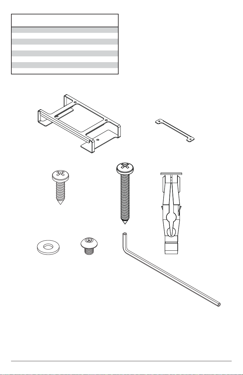
Parts List
Description Qty
A enclosure assembly 1 180-P1095
B locking fl ange 1 180-P1062
C #10 x 3/4” wood screw 2 500-9006
D #14 x 1-1/4” wood screw 2 510-9157
E anchor 2 590-0320
F #10 fl at washer 2 540-9442
G M5 X 6mm security screw 2 520-1114
H 4mm allen wrench 1 560-9646
F
A
C
G
D
B
E
H
4
2012-12-11 #: 180-9043-2 (2013-07-11)

Installation to Single Stud Wall
WARNING
• Installer must verify that the supporting surface will safely support the combined load of the
equipment and all attached hardware and components.
• Tighten wood screws so that wall plate is fi rmly attached, but do not overtighten. Overtightening
can damage the screws, greatly reducing their holding power.
• Never tighten in excess of 80 in. • lb (9 N.M.).
• Make sure that mounting screws are anchored into the center of the stud. The use of an "edge to
edge" stud fi nder is highly recommended.
• Hardware provided is for attachment of mount through standard thickness drywall or plaster into
wood studs. Installers are responsible to provide hardware for other types of mounting situations.
Use a stud fi nder to locate the edges of the stud and draw a vertical line down the center of the
1
stud. Place security bracket (A) on wall. Level and mark center of two mounting holes as shown
in fi gure 1.1. Drill two 5/32" dia. pilot holes to a depth of 1-1/4". Make sure that security bracket
(A) is level and secure it using two wood screws (D) as shown in fi gure 1.2.
A
A
D
fi g. 1.1 fi g. 1.2
5
2012-12-11 #: 180-9043-2 (2013-07-11)

Installation To Solid Concrete or Cinder Block
WARNING
• When installing the security enclosure on cinder block, verify that you have a minimum of 1-3/8"
(35 mm) of actual concrete thickness in the hole to be used for the concrete anchors. Do not drill
into mortar joints! Be sure to mount in a solid part of the block, generally 1" (25 mm) minimum
from the side of the block. Cinder block must meet ASTM C-90 specifi cations. It is suggested
that a standard electric drill on slow setting is used to drill the hole instead of a hammer drill to
avoid breaking out the back of the hole when entering a void or cavity.
• Concrete must be 2000 psi density minimum. Lighter density concrete may not hold concrete
anchor.
• Installer must verify that the supporting surface will safely support the combined load of the
equipment and all attached hardware and components.
Make sure that security bracket (A) is
1
level and use it as a template to mark two
mounting holes. Drill two 5/16" dia. holes to
a minimum depth of 2-1/2". Insert anchors
(E) in holes fl ush with wall as shown. Place
security bracket (A) over anchors and
secure with two wood screws (D).
1
Drill holes and insert anchors (E).
concrete
surface
E
WARNING
• Tighten screws so that the security bracket
is fi rmly attached, but do not overtighten.
Overtightening can damage screws, greatly
reducing their holding power.
• Never tighten in excess of 80 in. • lb (9
N.M.).
• Always attach concrete expansion anchors
directly to load-bearing concrete.
• Never attach concrete expansion anchors
to concrete covered with plaster, drywall,
or other fi nishing material. If mounting to
concrete surfaces covered with a fi nishing
surface is unavoidable, the fi nishing
surface must be counter bored as shown
below. Be sure concrete anchors do not
pull away from concrete when tightening
screws. If plaster/drywall is thicker than
5/8" (16 mm), custom fasteners must be
supplied by installer.
CUTAWAY VIEW
INCORRECT CORRECT
2
Place security bracket (A) over anchors (E) and
secure with screws (D). Tighten all fasteners.
D
A
E
D
A
6
2012-12-11 #: 180-9043-2 (2013-07-11)

Installation to Desk or Countertop
Note: The thickness of the mounting surface MUST be 1" or greater. If mounting to a surface
1
less than 1" thick, shorter mounting screws must be used (not included).
Position security bracket (A) on top or underneath a desktop or countertop surface and use it
as a template to mark two mounting holes. Drill two 1/8" dia. holes to a maximum depth of 3/4".
Secure using two wood screws (C).
DESK OR COUNTERTOP
A
C
7
2012-12-11 #: 180-9043-2 (2013-07-11)

Install the HDS200 Transmitter (not included) into security bracket (A). Position the retainer (B)
2
into the bracket so that the holes in retainer (B) line up with the holes in the security bracket (A).
A
B
Secure retainer (B) using two M5 X 6mm screws (G) and two washers (F). Tighten screws using
3
4mm allen wrench (H) provided.
G
F
8
2012-12-11 #: 180-9043-2 (2013-07-11)

LIMITED WARRANTY
®
Peerless Industries, Inc. (“Peerless-AV
free from defects in material and workmanship, under normal use, for the periods listed below, from the date of purchase by the original
end-user. At its option, Peerless-AV® will repair or replace with new or refurbished products or parts, or refund the purchase price of any
Peerless-AV® product which fails to conform with this warranty.
In no event shall the duration of any implied warranty of merchantability or fi tness for a particular purpose be longer than the
period of the applicable express warranty set forth above. Some states do not allow limitations on how long an implied warranty lasts,
so the above limitation may not apply to you.
This warranty does not cover damage caused by (a) service or repairs by the customer or a person who is not authorized for such service
or repairs by Peerless-AV
to follow Peerless-AV®’s instructions or warnings when installing, using or storing the product, or (d) misuse or accident, in transit or
otherwise, including in cases of third-party actions and force majeure. This warranty also does not cover corrosion or rust resulting from
damaged, scratched or chipped paint or other surfaces.
In no event shall Peerless-AV
product, whether or not secured by a security device which may be included with the Peerless-AV® product. Some states do not
allow the exclusion or limitation of incidental or consequential damages, so the above limitation or exclusion may not apply to you.
This warranty is in lieu of all other warranties, express or implied, and is the sole remedy with respect to product defects. No dealer,
distributor, installer or other person is authorized to modify or extend this Limited Warranty or impose any obligation on Peerless-AV
connection with the sale of any Peerless-AV® product.
®
, (b) the failure to utilize proper packing when returning the product, (c) incorrect installation or the failure
”) warrants to original end-users of Peerless-AV® products that Peerless-AV® products will be
®
be liable for incidental or consequential damages or damages arising from the theft of any
®
in
This warranty gives specifi c legal rights, and you may also have other rights which vary from state to state.
Product
Mounts
Furniture
Cables
Cleaning Products
Electronic Products and components
Warranty Period
5 years
1 year
25 years
1 year
1 year
9
2012-12-11 #: 180-9043-2 (2013-07-11)

Notes

Notes

Peerless-AV
2300 White Oak Circle
Aurora, IL 60502
Email: tech@peerlessmounts.com
Ph: (800) 865-2112
Fax: (800) 359-6500
www.peerless-av.com
© 2013, Peerless Industries, Inc.
 Loading...