

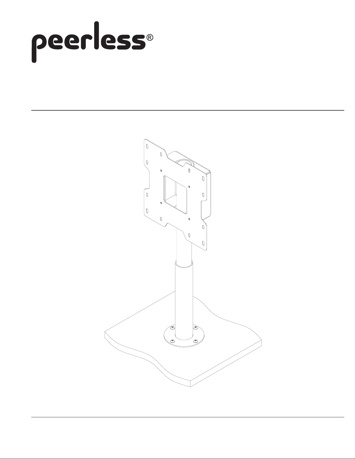
Installation and Assembly
Desktop Swivel Mount
Model: HP432-002, HP432-002-S, HP432-002-GB
Max Load Capacity: 80 lbs (36.3 kg)
3215 W. North Ave. • Melrose Park, IL 60160 • (800) 865-2112 or (708) 865-8870 • Fax: (708) 865-2941 • www.peerlessmounts.com
ISSUED: 8-29-07 SHEET #: 124-9102-3 8-13-08

Note: Read entire instruction sheet before you start installation and assembly .
WARNING
• Do not begin to install your Peerless product until you have read and understood the instructions and warnings
contained in this Installation Sheet. If you have any questions regarding any of the instructions or warnings, please
call Peerless customer care at 1-800-865-21 12.
• This product should only be installed by a qualified professional.
• Make sure that the supporting surface will safely support the combined load of the equipment and all attached
hardware and components.
• Never exceed the Maximum Load Capacity of 80 lbs (36.3 kg).
• Always use an assistant or mechanical lifting equipment to safely lift and position equipment.
• Tighten screws firmly , but do not overtighten. Overtightening can damage the items, greatly reducing their holding
power.
Table of Contents
Parts List.................................................................................................................................................................. 3
Installation to Desktop .............................................................................................................................................. 4
Installing Tube Assembly .......................................................................................................................................... 4
Installing Screen ....................................................................................................................................................... 5
For customer service call (800) 865-21 12 or (708) 865-8870.
2 of 5
Visit the Peerless Web Site at www.peerlessmounts.com For customer care call 1-800-865-2112 or 708-865-8870.
ISSUED: 8-29-07 SHEET #: 124-9102-3 08-13-08
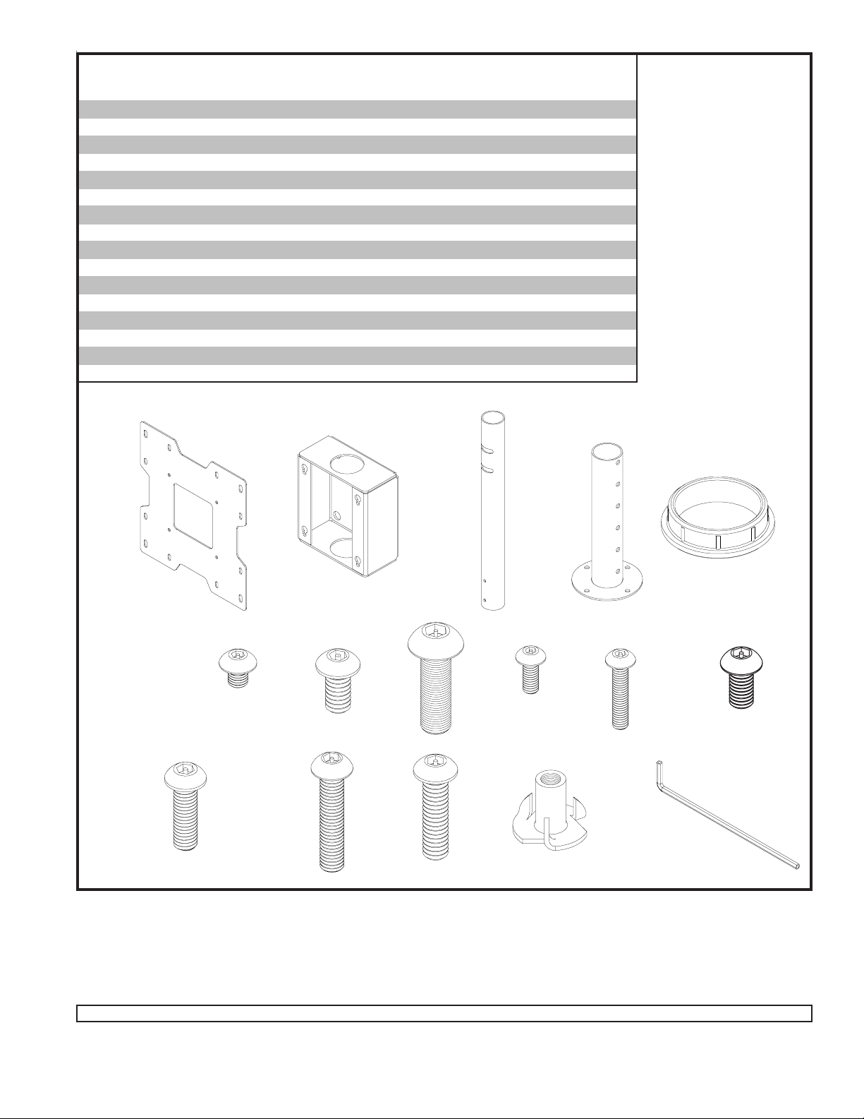
Parts List
De scrip tion QTY. Part #
adapter plate 1 095-1322 095-P1322 095-4322
A
adapter box 1 124-1794 124-P1794 124-4794
B
swivel tube 1 124-1792 124-P1792 124-4792
C
base tube 1 124-1796 124-P1796 124-4796
D
bushing 2 590-1088 590-1088 590-1088
E
M5 x 6 m m s ocket pin s crew 4 520-1114 520-1114 520-2062
F
1/4-20 x 1/ 2" s oc ket pin s c rew 2 520-1054 520-1054 520-2069
G
M8 x 25 m m s ocket pin s crew 2 520-1101 520-1101 520-2184
H
M4 x 10 m m s ocket pin s crew 4 520-1060 520-1060 520-2060
I
M4 x 20 m m s ocket pin s crew 4 520-1061 520-1061 520-2163
J
M6 x 12 m m s ocket pin s crew 4 520-1050 520-1050 520-2050
K
M6 x 20 m m s ocket pin s crew 4 520-9554 520-9554 520-2554
L
M6 x 30 m m s ocket pin s crew 4 520-1067 520-1067 520-2067
M
1/4-20 x 1" s oc k et pin sc rew 4 520-1053 520-1053 520-2588
N
1/4-20 T-nut 4 530-9301 530-9301 530-2301
O
4 mm sec uri t y all en wren ch 1 560-9646 560-9646 560-9646
P
HP432-002 HP432-002-GB HP432-002-S
A
L
F
B
G
M
H
N
C
O
D
E
I
K
J
P
Note: Read entire instruction sheet before you start installation and assembly .
3 of 5
Visit the Peerless Web Site at www.peerlessmounts.com For customer care call 1-800-865-2112 or 708-865-8870.
ISSUED: 8-29-07 SHEET #: 124-9102-3 08-13-08

CAUTION
• Installations to desktops that have a gap between two supporting boards are not acceptable mounting surfaces for the HP line of
desktop swivel mounts.
Determine mount position on desktop and using
the base tube (D) as a template, mark and drill
four 5/16" diameter holes through desktop.
Place base tube on desktop and secure using
four 1/4-20 x 1" socket pin screws (N) and four
T-nuts (O).
Note: The holes on base tube (D) will face the back of
the desktop.
D
N
Insert swivel tube (C) into base tube (D), adjust
swivel tube to desired height and secure using
two 1/4-20 x 1/2" socket pin screws (G).
C
G
D
O
Insert two bushings (E) into the two holes on
adapter box (B) as shown.
E
B
E
Place adapter box (B) onto swivel tube (C) and
secure using two M8 x 25 mm socket pin screws
(H). Be sure that screws (H) are positioned into
the slots in the swivel tube (C) and are fully
tightened.
B
H
C
Note: Narrow end of keyhole slot faces toward bottom.
4 of 5
Visit the Peerless Web Site at www.peerlessmounts.com For customer care call 1-800-865-2112 or 708-865-8870.
ISSUED: 8-29-07 SHEET #: 124-9102-3 08-13-08

Identify hole pattern on back of screen.
Note: Desktop mount only supports screens with a VESA 100, VESA 200 and VESA 400 hole pattern.
WARNING
• If screws don't get three complete turns in the screen inserts or if screws bottom out and bracket is still not tightly
secured, damage may occur to screen or product may fail.
FOR VESA® 100 MOUNTING P ATTERN:
Thread four screws (I or J) into screen leaving 1/8" exposed thread as shown in figure 5.1.
Hook screen onto keyhole slots of adapter box (B), then fasten four screws (I or J) through the back of adapter box into
adapter plate as shown in figure 5.2.
I or J
I or J
1/8" SPACE
B
TIGHTEN
FASTENERS
THROUGH
BACK HOLES
fig. 5.1
FOR VESA® 200 and VESA® 400 MOUNTING P A TTERN:
Attach adapter plate to screen using four screws (K, L or M). Thread four M5 x 6 mm screws (F) into adapter plate
leaving 1/8" exposed thread as shown in figure 5.3.
Hook screen onto keyhole slots of adapter box (B), then fasten four screws (F) through the back of adapter box into
adapter plate as shown in figure 5.4.
I or J
fig. 5.2
A
A
F
K, L or M
B
F
TIGHTEN
1/8" SPACE
FASTENERS
THROUGH
BACK HOLES
fig. 5.3
Visit the Peerless Web Site at www.peerlessmounts.com For customer care call 1-800-865-2112 or 708-865-8870.
F
fig. 5.4
5 of 5
All other brand and product names are trademarks or registered trademarks of their respective owners.
ISSUED: 8-29-07 SHEET #: 124-9102-3 08-13-08
© 2008, Peerless Industries, Inc. All rights reserved.
 Loading...