

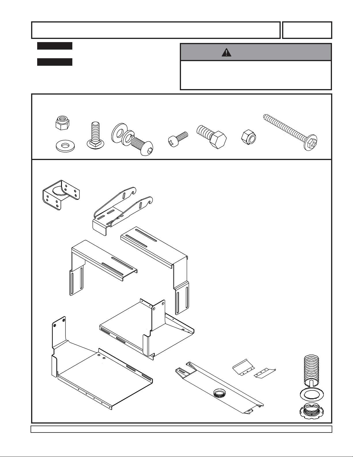
Installation and Assembly - CRT Ceiling Mount Kit for 14" - 17" Monitors
IMPORTANT! Read entire instruction sheet before you
start installation and assembly.
IMPORT ANT! This kit includes all mounting hardware
for direct attachment to a wood joist ceiling. For
concrete ceiling installations order accessory kit ACC
210. Fixed Length and adjustable extension columns
are also available.
Before you start make sure all of the parts shown below are included with your product.
• Installer must verify that the ceiling will safely support
four times the combined weight of all attached equipment and hardware.
WARNING
Model: IMC 18
N
A
B
L
E
H
I
C
F
G
D
U
PARTS LIST
J
K
M
O
PART # QTY. DESCRIPTION
A 530-9413 4 1/4-20 nylock nut
B 540-9440 4 1/4 SAE flat washer
C 520-9513 4 1/4-20 x 3/4" carriage bolt
D 520-9549 6 5/16-18 socket head screw
E 540-9406 8 5/16 SAE flat washer
F 540-9405 6 5/16 lock washer
G 520-9250 5 M5 x .8 x 10 mm phillips screw
H 520-9210 2 5/16-18 x 3/4" hex head bolt
I 530-9306 2 5/16-18 nylock nut
J 073-1007 1 hanging bracket
K 073-1008 1 tilt bracket
L 073-1001 1 left adjuster
M 073-1002 1 right adjuster
N 073-1003 1 left tray
O 073-1004 1 right tray
P 128-1039 1 ceiling plate
Q 2PT-22CA01D 2 ceiling plate end cap
R 1446-014 1 flush mount tube
S 1800-375 1 retaining collar
T 540-9432 1 fiber washer
U 5S1-015-C03 4 #14 x 2.5" (6 mm x 65 mm)
wood screw
Note: Parts may not appear exactly as illustrated.
Visit the Peerless Web Site at www.peerlessindustries.com
1 of 5
Q
R
T
P
S
ISSUED: 2-19-98 SHEET #: 073-9003-1 08-26-04
For customer service call 1-800-729-0307 or 708-865-8870.
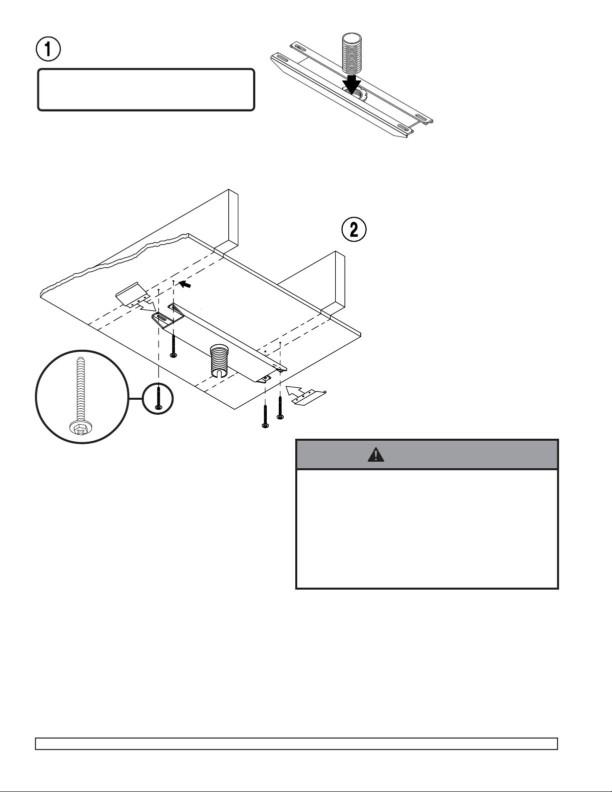
From the top thread flush mount tube (R)
through threaded fitting in ceiling plate (P).
IMPORTANT: If you will install an extension
column DO NOT INSTALL THE FLUSH
MOUNT TUBE.
Q
∅ 5/32" (4 mm)
P
R
P
For Wood Joist Finished Ceiling, Exposed Wood Joists, or Wood Beam
Ceiling. (See 3 for concrete ceilings). Drill
four 5/32" (4 mm) dia. holes to a minimum
depth of 2.5" (64 mm). Attach ceiling plate
(P) with four #14 x 2.5" (6 mm x 65 mm)
wood screws (U). Tighten wood screws so
ceiling plate is firmly attached. DO NOT
TIGHTEN WITH EXCESSIVE FORCE!
Overtightening can cause stress damage to
wood screws greatly reducing their holding
power! Tighten to 80 in • lb (9 N.M.) maximum torque.
Snap end caps (Q) into place.
U
Q
WARNING
• Tighten wood screws so that ceiling plate is firmly
attached, but do not overtighten. Overtightening can
damage the screws, greatly reducing their holding
power.
• Never tighten in excess of 80 in • lb (9 N.M.).
• Make sure that mounting screws are anchored into the
center of the joists. The use of an "edge to edge" stud
finder is highly recommended.
Visit the Peerless Web Site at www.peerlessindustries.com
2 of 5
ISSUED: 2-19-98 SHEET #: 073-9003-1 08-26-04
For customer service call 1-800-729-0307 or 708-865-8870.

WARNING
• Installer must verify that the ceiling will safely support
four times the combined weight of all attached equipment and hardware.
∅ 5/16" (8 mm)
Q
P
concrete
anchor
FOR PRODUCT SAFETY USE
ONL Y...
RAWLTM #5005 OR HIL TI
HL814 CONCRETE ANCHORS
[.312 x 1.625 (8 mm x 41 mm)].
ORDER ACCESSORY F ASTENER KIT #ACC 210
CONCRETE ANCHOR
INSTALLATION
Cross Section: Attachment
to a concrete ceiling.
TM
Q
For Concrete Ceilings drill four 5/16" (8 mm)
dia. holes to a minimum depth of 1 3/4" (45
mm). Attach ceiling plate (P) using concrete
expansion anchors as shown (left and next
page). Tighten to 80 in • lb (9 N.M.) maximum
torque.
Snap end caps (Q) into place.
WARNING
• Tighten concrete anchor bolt s firmly , but do not
overtighten. Overtightening can damage the bolts,
greatly reducing their holding power.
• Never tighten in excess of 80 in • lb (9 N.M.).
WARNING
• Always attach concrete expansion anchors directly to
load-bearing concrete.
• Never attach concrete expansion anchors to concrete
covered with plaster, drywall or other finishing material.
ceiling
STEP1: Hammer
in concrete
anchor.
Visit the Peerless Web Site at www.peerlessindustries.com
STEP2: Tighten to 80 in • lb (9
N.M.) maximum torque to
expand anchors.
3 of 5
CUT AW A Y VIEW
ISSUED: 2-19-98 SHEET #: 073-9003-1 08-26-04
For customer service call 1-800-729-0307 or 708-865-8870.

First: Assemble bracket as shown.
Leave all fasteners slightly loose to
allow for adjustment.
Second: From behind, insert
monitor into bracket. Face of
monitor should touch returns on
left and right trays (N & O). Adjust
height and width of bracket to fit
snugly around monitor.
Last: Tighten all fasteners!
A
B
K
monitor
C
L
M
N
E
F
return
D
O
G
return
Visit the Peerless Web Site at www.peerlessindustries.com
4 of 5
ISSUED: 2-19-98 SHEET #: 073-9003-1 08-26-04
For customer service call 1-800-729-0307 or 708-865-8870.

First: Choose tilt option (see "Tilt Options"
below).
P
J
R
H
R
S
J
H
G
Second: From inside, insert and tighten 5/16-
18 x 3/4" hex bolts (H) to hanger bracket (J).
Third: Attach hanger bracket using fiber
washer (T) and retaining collar (S). Tighten
retaining collar four or five complete turns.
Last: Align one hole in the side of the retaining collar with slot. From inside insert and
tighten one M5 x .8 x 10 mm phillips screw
(G) to lock retaining collar (S).
T
WARNING
S
• For safety retaining collar must be locked with screw!
Complete the assembly as shown.
WARNING
• Be sure to TIGHTEN ALL F ASTENERS SECUREL Y!
WARNING
• Always use an assistant or mechanical lifting equipment to safely lift and position the TV or monitor .
J
K
O
TILT OPTIONS - SIDE VIEW
0O to 20
Tilt Option One
Attach tilt bracket (K) to hanging
bracket (J) as shown for a tilt range
from 0O to 20O.
K
20
E
F
J
O
O
to 40
Tilt Option Two
Attach tilt bracket (K) to hanging
bracket (J) as shown for a tilt
range from 20O to 40O.
J
K
H
E
I
D
5 of 5
Visit the Peerless Web Site at www.peerlessindustries.com
© 2004 Peerless Industries, Inc. All rights reserved.
Peerless is a registered trademark of Peerless Industries, Inc.
All other brand and product names are trademarks or registered trademarks of their respective owners.
ISSUED: 2-19-98 SHEET #: 073-9003-1 08-26-04
For customer service call 1-800-729-0307 or 708-865-8870.
 Loading...