

Page 1
No. 434M
1356 ISOPERIBOL BOMB CALORIMETER
Service Manual
Page 2

Page 3

1. Calorimeter Operation
Operation……………………………………………………………………5
Corrections Fixed………………………………………………………… 6
Corrections and Final Report
Data Entry
Report Option …………………………………………………………… 7
Generate Report……………………………………………………………. 7
Display Reports …………………………………………………………… 8
Clear Memory
Edit Memory
Calorimeter Standardization ………………………………………………9
Heat of Combustion Calculation ………………………………………… 9
Calculations ……………………………………………………………….. 9
Correction Thermochemical……………………………………………….. 9
Details Thermochemical Calculation ……………………………………. 10
Sample Spiking ……………………………………………………………. 10
Spiking Sample Calculations ……………………………………………….11
Sample handling ………………………………………………………….12
2. 1108 Bomb Maintenance and Safety Instructions
Bomb Maintenance ……………………………………………………….. 11
500 Firings…………………………………………………………………. 11
3. Parts Replacement
Motor………………………………………………………………………. 14
Battery…………………………………………………………………….. 14
Cover adjustment………………………………………………………….. 14
Thermistor………………………………………………………………….. 15
Controller………………………………………………………………… 15
Controller Combined …………………………………………………….. 15
Keyboard
Cover Replacement………………………………………………………. 16
Support Rod ………………………………………………………………. 17
4. Error Messages
Preperiod/Postperiod
Misfire …………………………………………………………………… 19
Exceeded Calibration Limit………………………………………………. 19
Oxygen Charge Low……………………………………………………… 19
5. Miscellaneous
Misfire-wire intact
1356 Precison
Calculate Tests per Oxygen Cylinder
Volatile Spiking
Sulfuric acid correction …………………………………………………… 21
Use of inert gas-heat capacity
ISO/BSI corrections
…………………………………………………………………. 7
………………………………………………………………8
………………………………………………………………. 8
………………………………………………………………….. 16
……………………………………………………. 18
………………………………………………………… 19
……………………………………………………………… 20
…………………………………………………………… 21
……………………………………………………… 23
………………………………………………. 7
…………………………………….. 20
…………………………………………….. 22
Page 4

MSDS sheet benzoic acid…………………………………………………. 41
Data Logger 1356 ………………………………………………………… 24
Screen Bubbles ……………………………………………………………. 24
Stirrer Harness A1573E2………………………………………………….. 24
Replacing LCD Display and Keypad……………………………………. 25
Replacement I/O Board ……………………………………………………. 25
Longer Post Periods
Power Supply Board Replacement
CPU Board Replacement………………………………………………….. 27
6. Parts
5 year………………………………………………………………………. 27
Parts Information
5000 tests
Assembly Hinge ………………………………………………………….. 29
1563 Water Handling……………………………………………………… 30
7. Diagrams
Front View 1356 Calorimeter…………………………………………….. 32
Upper Link…………………………………………………………………. 33
Lower Link………………………………………………………………… 33
Left Linkage Bracket ……………………………………………………… 34
Right Mounting Plate ………………………………………………………35
Left Mounting Plate……………………………………………………….. 35
Right Linkage Bracket…………………………………………………….. 36
Cover Assembly 1356…………………………………………………. 37
Hinge Assembly…………………………………………………………… 37
1563 Flow Diagram……………………………………………………….. 38
1563 Electrical Diagrams………………………………………………….. 39
………………………………………………………………… 28
………………………………………………………. 25
……………………………………….. 26
………………………………………………………….. 27
4
Page 5

1. Calorimeter Operation
A. Operating the Calorimeter
All operations required to standardize the Calorimeter, or test an unknown sample, should
proceed step-wise in the following manner:
1. Turn on the calorimeter, go to menu page 1 and press YES key on line 3 to
activate the pump and heater.. The bomb parts should be wetted and then dried in
the manner used at the conclusion of a test. This serves to wet all sealing parts, as
well as leaving the bomb with the same amount of residual water which will exist
in all subsequent testing.
Prepare the sample and charge the oxygen bomb by attaching the hose to the
bomb and pressing the O2 Fill key.
The throughput of the 1356 Calorimeter can be increased by using multiple
bombs and water buckets. With this arrangement, the calorimeter can operate
almost continuously since the operator will be able to empty a bomb and recharge
it while a run is in progress. A bomb and bucket for the next run will be ready to
go into the calorimeter as soon as it is opened. Each bomb and bucket
combination will have to be standardized separately and the proper energy
equivalent for each set must be used for the heat of combustion calculation.
2. Fill the calorimeter bucket by first tarring the dry bucket on a solution or trip
balance; then add 2000 (+/- 0.5) grams of water. Distilled water is preferred, but
de-mineralized or tap water containing less than 250 ppm of dissolved solids is
satisfactory. The water temperature should be approximately 1 to 2ºC below the
room temperature. It is not necessary to use exactly 2000 grams, but the amount
selected must be duplicated within +/-0.5 gram for each run. Instead of weighing
the bucket, it can be filled from an automatic pipette, or from any other
volumetric device if the repeatability of the filling system is within +/-0.5 ml. Try
to make the starting temperature as repeatable as possible.
3, To speed and simplify the bucket filling process, and to conserve water and
energy, Parr offers a closed-circuit Water Handling System (No. 1563). This
provides a water supply, cooled to the starting temperature and held in an
automatic pipette ready for delivery in the exact amount needed to fill the bucket.
A 1552 Water Cooler is required when using the 1563 Water Handling System.
Instructions for this automatic system are given in Operating Instruction No. 245
and 246M.
4. Set the bucket in the calorimeter. Attach the lifting handle to the two holes in the
side of the screw cap and partially lower the bomb in the water. Handle the bomb
carefully during this operation so that the sample will not be disturbed. Push the
two ignition lead wires into the terminal sockets on the bomb head. Orient the
wires away from the stirrer shaft so they do not become tangled in the stirring
mechanism. Lower the bomb completely into water with its feet spanning the
circular boss in the bottom of the bucket. Remove the lifting handle and shake any
drops of water back into the bucket. Check for any bubbles coming from the
bomb, if bubbles are seen, do not fire the bomb. Resolve the problem.
5. Close the calorimeter cover
5
Page 6

Press the START key . The calorimeter will prompt for a Cal ID. The calorimeter
will then prompt for sample identification number by displaying Sample ID on
the display. Enter the correct sample ID by using any number, up to six digits, to
identify the sample. The calorimeter will check its memory and will not accept
duplicate sample ID numbers. Enter this value. The system will now prompt for a
sample weight, enter the sample wieght.
6. The calorimeter will now take over and conduct the test. During the time it is
establishing the initial equilibrium, it will display the PRE-PERIOD. Once the
bomb has been fired, the POSTPERIOD will be displayed. The calorimeter will
check to make certain that a temperature rise occurs and will then look for the
final equilibrium conditions to be met. If it fails to meet either the initial or final
equilibrium conditions, or if it fails to detect a temperature rise within the allotted
time, the calorimeter will terminate the test and advise the user of the error.
7. At the conclusion of the test, the calorimeter will signal the user and print the
results.
8. Open the cover, detach the lead wires from the bomb and remove the bucket with
the bomb. Remove the bomb from the bucket and open the knurled valve knob on
the bomb head to release the residual gas pressure before attempting to remove
the cap. This release should proceed slowly over a period of not less than one
minute to avoid entrainment losses. After all pressure has been released, unscrew
the cap, lift the head out of the cylinder and place it on the support stand.
Examine the interior of the bomb and fuel capsule for soot or other evidence of
incomplete combustion. If such evidence is found, the test will have to be
discarded.
9. Wash all interior surfaces of the bomb with a jet of distilled water and collect the
washings in a beaker.
10. Use Fixed Corrections or remove all unburned pieces of fuse wire from the bomb
electrodes; straighten them and measure their combined length in centimeters.
Subtract this length from the initial length of 10 centimeters and multiply this
burned length by 2.3 calories per cm (for Parr 45C10 Fuse Wire) to obtain the
fuse correction. The scale on the fuse wire card can be used to obtain this value
directly. If fixed corrections are used no entry is required.
11. Use fixed corrections or titrate the bomb washings with a standard sodium
carbonate solution using methyl orange, red or purple indicator. A 0.0709N
sodium carbonate solution is recommended for this titration to simplify the
calculation. This is prepared by dissolving 3.76 grams of Na2CO3 in the water and
diluting to one liter. NaOH or KOH solutions of the same normality may be used.
Enter the titer value for the acid correction. If fixed acid corrections has been
programmed, no entry is required.
12 Analyze the bomb washings to determine the sulfur content of the sample if it
exceeds 0.1 percent. Methods for determining sulfur are discussed in Operating
Instructions No. 207M.
13. Turn off the calorimeter at the power switch.
6
Page 7

B. Entering Corrections and Obtaining the Final Report
Final reports for each test can be obtained via the REPORT key, whenever the user is
prepared to enter the corrections for acid, sulfur and fuse.
Refer to the Reporting Generation for the steps necessary to initiate a report from the
calorimeter.
C. Manual Entry
During the reporting process, the calorimeter will prompt the user to enter the following
values:
Fuse Correction: Key in the Fuse Wire Correction and press the ENTER key. The default
setting for this value is to be entered in calories.
Acid Correction: Key in the Acid Correction and press the ENTER key. The default
setting for this value is to be entered in milliliters of standard alkali required to titrate
total acid or calories.
Sulfur Correction: Key in the Sulfur Correction and press the ENTER key. The default
setting for this value is entered as percent sulfur in the sample.
Enter these values when requested by the corresponding prompt. After the last entry has
been made, the calorimeter will automatically produce a final report. If values for these
corrections are not available, the user can use the SKIP key to pass over any of these
corrections. However, a final report will not be printed until an entry is made for each of
the three correction factors.
D. Fixed Corrections
In many cases, fixed values for fuse and acid can be used without introducing a
significant error since the corrections are both relatively small and constant. Fixed sulfur
corrections can also be used whenever a series of samples will be tested with a
reasonably constant sulfur content. Details for applying fixed corrections are found in the
Details Thermochemical Calculation Any value setup as a fixed correction will be
automatically applied and the calorimeter will not prompt the user for this value.
E. Report Option Selection
Data can be transferred over the RJ45 port to a 40 or 80 column printer to provide a
printed report. This port can also be used to transmit data to a host computer. In this case,
the data will have to be received, stored and formatted by programs residing in the host
computer. If you wish to transfer data to a computer ask for software from Parr, we can
quote a price for the software.
The default setting sends the calorimetric reports to the printer.
F. Report Generation
There are two kinds of calorimeter reports, which can be issued; preliminary and final.
Preliminary reports are generated at the conclusion of a test run when one or more of the
calorimeter corrections (FUSE, ACID, SULFUR, SPIKE) is not fixed. A final report
contains all of the final or fixed calorimetric corrections needed in order to give either an
energy equivalent or heat of combustion value.
7
Page 8

Reports may be obtained by pressing the REPORT key. To obtain a block of reports
between two specified sample numbers, press the REPORT key. Enter the first sample
number to the display, and press the ENTER key. The system will then prompt for the
last sample ID, if only one report is desired enter the same sample ID, followed by the
ENTER key. If a block of reports is desired enter the last sample in the block followed by
the ENTER key. During the reporting process, the printed reports will indicate whether
the reports are final or preliminary. The preliminary reports will require corrections to be
entered.
Preliminary reports will remain preliminary and the energy equivalent or heat of
combustion value, which is reported will reflect the fixed constants as set by the operator.
The printing of large numbers of reports may be avoided at any time using the RESET
key. The reset action will take effect after the current report has been completely
transmitted.
G. Displayed Reports
Reports may also be obtained through the display on the 1356 Calorimeter. The
procedure for obtaining reports on the display is the same as for obtaining printed reports.
The calorimeter will hold data for 500 tests within its memory. These tests may be either
preliminary, final, determination or calibration reports. Once the memory of the
calorimeter is filled, any attempt to start a new analysis will cause the calorimeter to
display MEMORY FULL, to avoid this error message go to Menu page 7 and line 6.
Change the Overwrite from OFF to On, then the oldest test will be deleted and replaced
by the most recent test. The alternative is to clear memory of tests.
H. Clearing Memory
This capability allows the user to delete Sample ID numbers and all related data and
results for a single report, a sequence of reports or for all reports.
To clear a single report, press the CLEAR MEM key. The calorimeter will prompt for the
first sample number in the block and then prompt for the last sample number in the block,
then press the ENTER key. To clear all reports, use the sequence procedure with 1 as the
first sample number and 999999 as the last number of the sequence.
I. Editing Memory
The user is able to add data and information to the previously gathered information for a
test by using the Memory Editing procedures described in the manual on page 8-1.
Press the F3 key. The calorimeter will then prompt for the first sample number, which is
keyed in and press the Enter key. The calorimeter will then prompt for the las t sample
number in the block, enter the ID and press the Enter key. If one wishes to edit one
sample, then enter the same number for the first and last sample ID. Highlight the data
field to be edited by pressing the Up or Down Arrow key
8
Page 9

Press the Clear key, enter the new value on the keyboard and press the Enter key. This
sequence is canceled by pressing the RESET key. Press the Escape key, when one is
done editing. If more than 1 sample is to be edited, the screen will display the next
sample’s information.
J. Standardizing the Calorimeter
The calorimeter will calculate the average EE value from standardization tests that have
been made.
K. Calculating the Heat of Combustion
While the Model 1356 Calorimeter will automatically make all of the calculations
necessary to produce a gross heat of combustion for the sample. It is important that the
user understand these calculations to ensure that the instrument is set up so that the
calculations match the procedures used and that the units are consistent throughout the
entire procedure and calculations.
L. General Calculations
Basically, the calculation of the gross heat of combustion is done using the following
equation:
Where:
Hc =Gross heat of combustion.
T =Observed temperature rise.
EE =Energy equivalent of the calorimeter being used.
e1 =Heat produced by burning the nitrogen entrapped in the bomb to form nitric acid.
e2 =Extra heat produced due to burning sulfur to sulfur trioxide and forming sulfuric
acid instead of sulfur dioxide.
e3 =Heat produced by the burning fuse wire.
m =Mass of the sample.
For convenience and by tradition, these calculations are made in calories, grams,
and degrees Celsius, and then converted to other units if required. The other units desired
are set on Menu page 2, line 2.
Temperature rise
automatically. Corrections for heat leaks are applied automatically. Similarly, the method
for extrapolating the end point of the test is discussed in the dynamic method description.
Energy equivalent
abbreviated as EE) is determined by standardizing the calorimeter as described in the
Standardization Section of the calorimeter manual. It is an expression of the amount of
energy required to raise the temperature of the calorimeter one degree. It is commonly
expressed in calories per degree Celsius. Since it is directly related to the mass of the
calorimeter, it will change whenever any of the components of the calorimeter (i.e. the
bomb, bucket, or amount of water) is changed.
M. Thermochemical Corrections
Nitric acid correction
. The 1356 Calorimeter produces a corrected temperature rise reading
. The energy equivalent (represented by W in the above formula, or
. In the high pressure oxygen environment within the oxygen bomb,
9
Page 10

nitrogen that was present as part of the air trapped in the bomb is burned to nitric oxide
which combines with water vapor to form nitric acid. All of this heat is artificial since it
is not a result of the sample burning.
Sulfur correction. In the oxygen rich atmosphere within the bomb, sulfur in the sample is
oxidized to sulfur trioxide, which combines with water vapor to form sulfuric acid. This
liberates additional heat over the normal combustion process, which converts sulfur to
sulfur dioxide. The sulfur correction removes this excess heat from the calculations.
Fuse wire correction. The wire used for a fuse to ignite the sample is partially consumed
in the combustion. Thus, the fuse generates heat both by the resistance it offers to the
electric firing current and by the heat of combustion of the wire that is actually burned. It
is normally assumed that the heat generated by the electrical resistance will be the same
when standardizing the bomb and when testing an unknown sample, and can therefore be
ignored. Significant variances can, however, occur in the amounts of fuse wire actually
burned in each test. So this energy is subtracted to account for the heat of combustion of
the metal.
N. Thermochemical Calculation Details
Traditionally, standard solutions and procedures have been established to simplify the
calculations and thermochemical calculations.
ACID and SULFUR Corrections. In certain ASTM methods, the amount of sodium
carbonate used to titrate the bomb washings is equated with e1.
Users may find it convenient to enter a fixed value for the acid correction and avoid the
need to determine this correction for each test. To enter Fixed Acid Corrections,go to
Menu page 5 and turn on line 1 Fixed Fuse for Standardization or line 4 for
Determination. Total errors of more than 3 calories will seldom occur when using Fixed
Acid Corrections.
Fixed Sulfur Corrections can be entered if a series of samples contain a constant amount
of sulfur. For Standizations, line 3 is always ON. For determination runs to enter Fixed
Sulfur Corrections, turn on Line 6 and enter the estimated value.
O. Spiking Samples
It is sometimes necessary to add a spiking material to samples, which are very small,
have a low heat of combustion, or have a high moisture content to add sufficient heat to
drive the combustion to completion. Benzoic acid is an excellent material for spiking for
all of the same reasons that it is a good standard material. White oil is also an excellent
material; particularly for liquid samples. The 1356 Calorimeter can automatically
compensate for the addition of spiking materials to these samples.
When Use Spiking is turned on, on Menu page 2.3 and line 1, the heat of combustion of
the spiking material must be entered on Menu page 2.3, line 2.
During data entry when using a spike, the calorimeter will prompt for both the sample
weight and the spike weight.
10
Page 11

Spiking Calculations
[{EE x T(temp rise)}-e1-e2-e3-[mass(oil) x Heat Combustion(oil)]/sample m grams
2. 1108 Oxygen Bomb Maintenance and Safety Instructions
Oxygen Bomb Maintenance
Under normal usage Parr oxygen bombs will give long service if handled with reasonable
care. However, the user must remember that these bombs are continually subjected to
high temperatures and pressures which apply heavy stresses to the sealing mechanism.
The mechanical condition of the bomb must therefore be watched carefully and any parts
that show signs of weakness or deterioration should be replaced before they fail.
Otherwise, a serious accident may occur.
Do not fire the bomb if gas bubbles are observed anywhere indicating a possible gas
leak. Disassemble the parts and install new seals immediately.
Keep the 397A compression nut on the valve needle tightened firmly at all times.
Frequent tightening is important. This nut, if slightly loose, may allow a leak to develop
during the rapid pressure rise upon ignition. This type of leak may not be detectable
before firing; but if it develops, the hot gases can ignite the 20VB valve seat and burn
through the head.
Do not use extreme force when closing the needle valve. A moderate but firm turn on
the valve knob should be sufficient to stop all gas flow. Excessive needle pressure will
deform and possibly close the gas passage. If this happens, unscrew the valve body and
replace the 20VB valve seat. Accumulated salt deposits may also clog the gas passage,
making it difficult to release pressure at the end of a run. To avoid this, clean the passage
through the valve needle and deflector nut with a small drill.
Firings 500
All O-rings and 20VB valve seats should be replaced after 500 firings for the standard
1108 Oxygen Bomb and 250 firings for the 1108CL Oxygen Bomb for chlorine content
of samples is 25% or greater.
A Parr 475A service clamp offers a convenient means for clamping the bomb head firmly
in a vise without damaging the head when replacing any of the bomb head parts.
When replacing the 230A head gasket, stretch the new O-ring and let it snap into place to
be sure that it moves freely in its groove and is not twisted.
To replace the valve seat, unscrew the 397A compression nut; remove the valve stem and
the old seat, and disassemble all of the parts. Drop a new 20VB valve seat into the body
and push it down into place. Slide a 7VBCM Monel washer, two 238A O-rings and
the 378A packing cup onto the valve needle with the needle pointed upward; then adjust
the parts on the needle so that the tip of the needle is flush with or slightly recessed into
the bottom of the packing cup. Insert this assembly into the 369A outlet valve body and
press it firmly against the valve seat by tightening and 397A compression nut to 100
inch-pounds of torque.
The 238A sealing ring in the insulated electrode should be replaced with the same
frequency as the 20VB valve seat. Also keep the 411A terminal nut tight at all times. As
11
Page 12
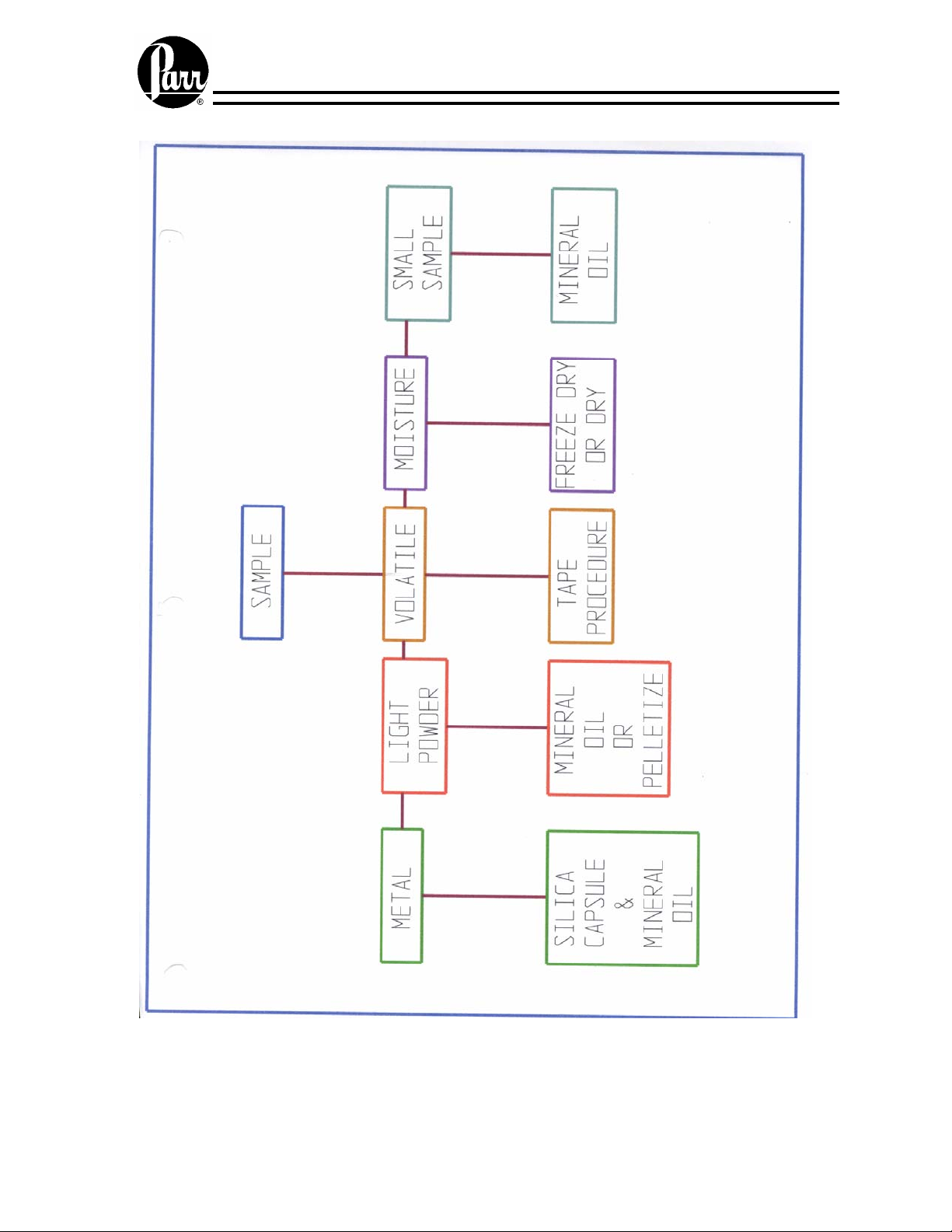
Sample preparation
12
Page 13

the 238A sealing ring ages and hardens it becomes a partial electrical conductor,
permitting misfires and producing unwanted heating effects. Periodic replacement will
eliminate this potential problem.
The threads on the screw cap should be checked routinely for any burrs or other
deformity. After long use, the threads on the screw cap may become worn to the point
where they will no longer provide a safe closure for the bomb, and the screw cap will
have to be replaced. The following procedure can be used to check the extent to which
the threads have become worn.
Assemble the bomb with the head in the cylinder and count the number of turns required
to bring the screw cap down firmly against the head. Then open the bomb; remove the
head and replace the screw cap, but turn it down to only one-half of the turns previously
counted. This will usually be about four turns. With the screw cap in this position, use a
dial gage to measure the vertical deflection when lifting the screw cap upward. If this
measurement exceeds 1/32 inch (0.030”), the screw cap is unsafe and should be
discarded. The cylinder can then be returned to the factory for inspection. If the threads
on the cylinder are in good condition, a new screw cap can be custom-fitted to the
cylinder.
Never under any circumstances use oil on valves or fittings which handle
compressed oxygen. This precaution applies to all of the oxygen bomb parts as well as to
the oxygen filling connection.
The 1108CL Bombs will resist chlorine, fluorine or bromine in the presence of moisture.
If samples yielding appreciable amounts of these elements are burned in a Parr bomb, the
bomb should be emptied and washed as quickly as possible after each combustion.
If the interior of the bomb cylinder should become etched, the resistance of the metal to
further attack can be improved by restoring the surface to its original highly polished
condition. Bombs needing polishing or other repair work can be returned to the factory.
A periodic overhaul and test at the factory will help to keep any Parr oxygen bomb in
first-class condition.
Parr oxygen bombs can be returned at any time for repair and testing. A factory test is
recommended after every 5000 firings, or sooner if the bomb has been subject to any of
the following conditions: (a) fired with an excessive charge, (b) ignition of any internal
components, (c) machined by any source other than the factory, (d) damaged by corrosive
vapors that might have exceeded 80% of the corrosion allowance, or (e) any changes in
the threads on the bomb cylinder and/or screw cap. When returning a bomb to the
factory, ship it to Parr Instrument Company, 211-53rd Street, Moline, Illinois 61265, with
the package marked for the attention of the Repair Department. A purchase order
covering the repair work should be included with the shipment or mailed to the same
address, as no repairs will be started without specific instructions. Be sure to include a
return shipping address and the name and telephone number of the individual to be
contacted if questions arise concerning excessive repair costs or other problems.
Individual repair parts can be ordered from any Parr dealer or direct from the factory.
13
Page 14

2. Parts Replacement
Keyboard
A bad keyboard panel will result in the calorimeter responding to only some rows or
columns of keys and ignoring others. If the keyboard has failed completely, the
calorimeter will respond to no key activation. Keyboard. In either case, the calorimeter
will power-up to the main menu..
Instructions for Adjusting Cover
1. Turn off instrument and open cover.
2. Loosen 8 set screws that secure the lower link assemblies, S shaped, to the
assembly shaft rod, Hinge Assembly
3. Carefully move the cover to the closed position.
4. From the rear of the calorimeter, with a nut driver or socket wrench, loosen the
six kep nuts that secure the support rod mounting place to the calorimeter chassis
5. Align cover so that cover has a uniform alignment with calorimeter chassis, front
side and rear. No air gap should exist between rear portion of cover and the
calorimeter chassis.
6. Position the lower linkage assemblies to outer most position against the support
rod mounding plate.
7. Now secure the nuts on the support rod mounting plates, alternating between left
and right hand plates until all six nuts have been tightened.
Raise the cover and recheck the lower linkages to be sure they are at outer most
position adjacent to the respective mounting plates. Secure the 8 set screws.
8. Lower cover and recheck cover adjustment.
Motor Replacement
Remove the stirrer shaft assembly from the motor coupler.
From the bottom side of the cover, remove the 12 button head socket screws that secure
the top cover of the metal plate. Remove the motor’s electrical leads from the terminal
strip and note the terminal connection for each lead wire. Remove the 2 round head
screws that secure the motor to the cover and transfer the coupler to the new motor.
1404E Battery
The controller must be removed from the calorimeter. Remove the 6 screws that secure
the beige rectangular ring on the keypad. Remove the thermistor connectors from the
controller and remove the two orange connectors from the side of the controller. Remove
the power cord. Swing the controller out of the opening in the calorimeter. Remove the
ribbon connector from the display board and remove the power cord for the display, 2
wires, red and black. Remove the 4 nuts that secure the smart link connectors
on the back panel. Remove the 7 phillip screws that secure the left side panel to the
control module at the side and bottom of the left side chassis. The battery is secured to
14
Page 15

the left side panel via velcro and is located between the power supply board at the front
and the cpu board and is connected electrically to the cpu board. Remove the connector
and replace the battery.
Bucket Thermistor Replacement
Open the calorimeter cover, and turn off the instrument. Use a 5/64 Allen wrench to
remove the 12 button head screws which secure the cover to the bottom plate of the
cover assembly Front View 1356 Calorimeter
be removed with the cover in a not fully pushed back position. Before removing the last
screw, grasp the cover assembly so that it does not drop and become damaged Remove
the 2 cable clips which secure the thermistor cable to the hinge assembly. With the cover
closed, remove the nut and plastic ferrule which secures the probe to the cover water
jacket assembly, Cover Assembly 1356. Remove the probe from cover through the cover
and jacket hinge openings. Disconnect the BNC connector from the microprocessor case
Front View 1356 Calorimeter
thermistor probe and secure to the cover with the previously removed nut and ferrule.
Controller Removal
The 1356 Calorimeter Controller can be physically separated into two halves. The upper
logic pack consists of the keyboard, and display. The lower half consists of power supply
board, microprocessor board and the I/O board.
1. Disconnect the power cord from the rear of the controller, remove the thermistor
connectors, remove the 2 orange connectors..
2. Remove the six screws located on the display bezel.
3. Remove the bezel.
4. Separate the logic pack from the power pack by lifting the logic pack up from the
lower edge.
5. Unplug the 4 conductor, shielded, thermistor probe cable from the logic pack at
P4. Note that the red wire of the cable goes to Pin 1 in the logic pack.
Unplug the two ribbon cables using the two ejectors on the mating sockets.
Combined Controller Removal
The 1356 Calorimeter Controller can be physically separated into two halves. The upper
logic pack consists of the keyboard, and display. This display is attached to the lower
power pack with one ribbon cable that is connected to the cpu board and a two wire cable
that is connected to the power board. Six screws are used to mate the display to the lower
unit.
1. Disconnect the power cord and any Smart Link and/or printer cables from the rear
of the controller.
2. Disconnect the two orange connector plugs from the side of the controller.
3. Disconnect the BNC connectors attached to the ends of the bucket and jacket
thermistor probes.
. Reversing the above removal procedure, install the new
). The screws at the rear of the cover must
15
Page 16

4. Remove the six screws located on the display bezel and remove the bezel.
5. Push the rear of the controller near the bottom of the case, which will force the
display panel up.
6. Grab hold of the front edge of the controller which has been forced up in the
preceding step, and guide it out of the front of the calorimeter case, tilting where
necessary to provide clearance of the BNC jacks.
7. The display and lower half may now be separated, if desired, by following the
procedure given for the logic pack removal. If the controller is returned to Parr,
they may be secured together with screws. Otherwise, they must be separated to
avoid damage in transit.
Keypad
When any row or column of keys fail on the keyboard panel of a 1356 Calorimeter, the
panel is not repairable and must be replaced. A replacement keyboard panel can be
ordered from Parr (Parr Part No. 1601E). Replace the keyboard panel by removing the
controller from the 1356. For removal see;. Controller Combined .
Instructions for Replacing Support Rod Mounting Plates
1. Turn off instrument, disconnect harness plugs from the controller and open cover.
2. Loosen 8 set screws that secure the lower link assemblies, S shaped, to the
assembly shaft rod.
3. Remove the socket head machine screws from the lower linkages which connect
to cover brackets. These flat head machine screws and retaining washers have been
fastened with Loctite which may require more than normal effort to loosen them. Care
must be exercised in this step as the cover may slip down and possibly bend the
thermistor probe.
4. Remove the round head machine screw that secures the tube clips to the lower
linkages.
5. Carefully move the cover to the closed position.
6. Remove 2 socket head machine screws that secure the upper linkage to the
support rod mounting plates.
7. From the rear of the calorimeter, with a nut driver or socket wrench remove the
six kep nuts that secure the support rod mounting plate to the calorimeter chassis.
8. Remove 2 snap rings that secure the retaining pin to the upper U bracket and gas
spring, and remove retaining pin.
9. The lower linkages that were previously loosened via set screws can now be
moved toward the center on the shaft assembly rod.
11. Lower the shaft assembly rod and remove both support rod mounting plates from
the shaft assembly rod.
16
Page 17

12. Position the new mounting plates on the shaft assembly rod. Raise the shaft
assembly rod to position the support rod mounting plate over the machine screws
attached to the calorimeter chassis.
13. Secure the mounting plates with previously removed kep nuts, finger tight.
14. With previously removed flat head machine screws and retaining washers, secure
the upper linkage to the support rod mounting plates.
15. Use the retaining pin to secure the gas spring to the U bracket. Reattach the snap
rings on the retaining pin.
16. Push the lower linkages to the outer most position on the shaft assembly rod.
Raise cover to open position.
17. Attach tube clips to the lower linkage assembly with the nut and washer between
the two linkage assemblies.
18. Reattach lower linkage arms to the cover bracket with the flat head machine
screws and retaining washers. Position the lower linkage assemblies to outer most
position against the support rod mounting plate.
18. Position the lower linkage assemblies to outer most position against the support
rod mounting plate.
19. Lower the cover and align cover so that cover has a uniform alignment with
calorimeter chassis, front, side and rear. No air gap should exist between rear portion of
cover and the calorimeter chassis.
20. Now secure the nuts on the support rod mounting plates, alternating between left
and right hand plates until all six nuts have been tightened.
21. Raise the cover and recheck the lower linkages to be sure they are at outer most
position adjacent to respective mounting plates. Secure the 8 set screws.
Reattach cable connector, lower cover and recheck cover adjustment.
4. Messages Error
Error: Pre-period/Post-period Time Limit Violated
Pre-period or Post-period Time Limit Violation. The causes are listed in order of
probability.
1. The stirrer motor does not work or is intermittent, which is generally due to
weak torque capability. With cover open and stirrer operating, one should
not be able to stop stirring with gentle force of two fingers. Another test is to
open and close the lid, if the motor stops during this process, replace the
A1537E2 wiring harness
2. The bucket tipped so as to touch the wall of test chamber.
3. Water in the bottom of test chamber.
4. The bucket temperature is started at temperatures which are more than 1-2
degrees C below the room temperature.
5. Bad motor cable, Parr A1537E2 or feet on the bomb are worn so water circulates
under the bomb.
6. Oxygen leak in the bomb or foam insulation has deteriorated.
7. Bucket thermistor probe bent and touching the bucket.
17
Page 18

8.
Misfire Error
Ignition Problems on the 1356 Calorimeter are generally attributed to one of three
possible sources, after having checked the fuse.
1. Breakdown of insulator and O-ring on the insulated electrode assembly. Any
reading on an ohm meter when set on RX1 scale when the ohm meter leads are connected
to the ignition terminals of oxygen bomb head is an indication of insulation breakdown.
2. The ignition lead wires have broken internal wire strands which may be detected
by connecting the ohm meter to the ends of the wire, and flexing the wire. Any change in
the reading of approximately from 0-20 ohms would indicate broken strands of wire.
Readings for bad ignition wires generally go to infinity on flexing the wire.
3. The third possibility is the connection termination of the 11 pin Wago connector
to the A1135DD control unit. The wire terminations for ignition wire are not fully
inserted into the orange connector. The voltage output from the 11 pin connector on the
A1135DD control unit may be confirmed with volt meter measurement at pins 6 and 7.
When one turns on line 1 of menu page 9.2 and voltage on large blue capacitor inside the
controller should ramp to approximately 30 volts. If system does not show any ramping,
the charging circuit is at fault. If capacitor charges but the fuse wire does not burn, the
discharge circuit is at fault.
4. Improperly formed fuse wire may cause misfire. The fuse should be attached by
raising the cap, inserting the wire through the eyelet and then pull the cap downward to
complete the assembly. The bottom portion of fuse wire should touch sample before any
portion of wire touches the capsule.
Error: Calibration Limit Exceeded
This error is generally attributed to a calibration test that caused the range of calibration
tests to be larger than 12 calories/C. The cause of this may be due to the fact that:
1. The oxygen bomb has 500 firings and requires the replacement of O-rings and
valve seat.
2. The operator may have used the wrong bomb, that is each bomb is required to
have its own EE value.
3. An operator is different than the person that established the original EE value, it
may be necessary for each operator to have their own EE value.
4. The EE value may be an outlier and discarded after using a statistical review
procedure.
5. Discard the first calibration test
6. Be sure that bucket is dried after each run as well as the bomb and the probe and
stirrer.
7. All tests should be made at the same starting temperature.
18
Page 19

Low Oxygen Charge
Low Oxygen Pressure - signifies low oxygen pressure in the line filling the bomb. The
pressure switch must reach 27 (400 psi) atmospheres in this line otherwise there is the
display of this error message. Our recommended oxygen line pressure to the calorimeter
is 440-450 psi to allow for some pressure drop in the line to the calorimeter’s oxygen
solenoid
The most common cause is low oxygen pressure in the oxygen cylinder. Another
common reason for this error message is partially plugged orifice at the input of the
oxygen solenoid block and generally occurs when replacing the oxygen tank. We
recommend wiping the threads on the oxygen cylinder before attaching the oxygen
Regulator to the replacement tank. Close the valve for the oxygen tank. The problem may
be resolved by reversing oxygen connections at the solenoid block assembly. .Move the
connection from the input connector of the block to the output connector of the block
assembly. Cycle the oxygen fill process with the tank valve open to flush any particles
which may be blocking the orifice. After the completion of the fill process, close the
oxygen tank valve to avoid emptying the tank. If the error 78 message occurs at the end
of this process, oxygen is not flowing to the solenoid block assembly or the pressure
switch is faulty. If oxygen is being supplied to the block, then failure of the pressure
switch to close may be confirmed with an ohm meter measurement of approximately zero
resistance across pins 10 and 11 of the 11 position Wago Connector during the fill
process with the oxygen connections still in the reversed position. If one does not have a
filter in the oxygen line to the calorimeter, we recommend that a 359VB filter be
installed.
5. Miscellaneous
Accuracy & Precision-1356 Calorimeter
There are several considerations on must review to obtain the utmost accuracy and
precision. The water should be measured as accurate as possible, if one measures the
water to .5 ml or grams, this should be sufficient for most work.
1. The water residue in the bucket and on the bomb should be removed after each test.
2. The sample should be weighed to a minimum of .1 mg, preferably to .01 mg for each
test.
3. The acid titer should be made after each calibration test.
The fuse wire should be measured after each test.
4. The calibration tests should be reviewed to ensure that good work is being done. The
range of the calibration tests should not be greater than 12 cal/C. to give a relative
standard deviation of .20% which all 1356 calorimeters are capable of obtaining.
5. The starting temperature of each test should be T temperature +/- 1 C. for the best
accuracy
19
Page 20

Oxygen Use
P1A Oxygen Cylinder volume of cylinder 43.8 liters pressure of cylinder 2490 psi
V x P = 109062 liters-psi
Amount of gas per test = .350 liters x 450 psi = 158 psi-liter
No. of tests = 109062 psi-liter/158 psi-liter= 700 tests per cylinder
Spiking Volatile Waste Samples
Determine the heating value of mineral oil based on a minimum of 6 combustion tests.
Store this value in menu page 2.3 line 2. Go to menu page 2.3 and turn on line 1. Entered
value must be in cal/g and typical value is 11000 cal/g.
Cut a square portion from the 517A tape, which is chlorine free and apply to the fuel
capsule. Trim to the circumference of the capsule leaving one tab to fold back so that
material can be added to the capsule. The amount of tape used for covering the capsule
will be .0502 gm +/- .002 g. The tape will have a heat of combustion value of
approximately 6300 cal/g, and correction for the tape would be 316 calories +/- 12.6
calories. If this variation is insignificant relative to your application, then you might add
this value to fixed fuse correction and enter the sum on menu page 5 line 4, and turn on
fixed fuse..
If this value is significant, you might consider adding your fuse and acid correction and
entering the total for a fuse correction. Then one can use the nitric acid entry as means for
correcting for the tape. Menu page 5 line 5 should be off. Take the heat value of the tape
divided by 14.1 and multiply the result by the weight of the tape and enter this value on
Menu page 5 line 5. This assumes that a fixed value is used for the sulfur correction is
turned on. When requesting a report, the system will prompt for the nitric acid value. The
entry will be the weight of the tape.
Recommended procedure for all waste samples would be:
1. Cut, add tape to crucible, trim and leave tab to fold back.
2. Add .45 g of mineral oil
3. Add .1 g of sample
4. Seal capsule, load into bomb, and proceed as normal
Acid Sulfuric Calculations
The factor used to convert percent sulfur concentration to calorie correction in the heat of
combustion calculation for liquid hydrocarbon fuels is different than the factor for solid
fuels. The following table lists the differences between fuels.
20
Page 21

1. Solid Fuels (D2015)
Heat of Formation of .... 29KJ/mole
Sulfuric Acid for a Fuel with 5% sulfur and 5% hydrogen
S02(g) + 1/2 02(g) + H20(1) >H2S04 in 15 moles H20
e2 = 23.7 BTU/LB x %S x 1gm = x BTU gm/LB or
e2 = 13.17 cal/gm x %S x 1gm = x cal
2. Liquid Hydrocarbon Fuels (D240)
Heat of Formation of......301.KJ/moleSulfuric Acid for a fuel with .8% sulfur and 20%
hydrogen.
S02(g) + 1/2 02(g) + 651H20 > H2S04 650H20(1)
e2 = 14 cal/gm x %S x 1gm = x cal
GAS EFFECTS CALORIMETRY
There are occasions when the calorimeter is used to test
heat powders or similar materials in an inert atmosphere.
The question then becomes what is the effect on the heat
capacity when this change is made.
360 ml oxygen bomb x30atms/10800 ml or 10.8 liters
1. Oxygen
1.429 gm/liter x 10.8 liters = 15.43 gms
.219 cal
gm K K
2. Argon
1.784 gm/liter x 10.8 liter = 19.27 gms
.124 cal x 19.27 gm = 2.39 cal
gm K K
3. Helium
.1785 gm
1.24 cal x 1.93 gm = 2.39 cal
gm K K
x 10.8 liter = 1.93 gm
x 15.43 = 3.38 cal
21
Page 22

4. Nitrogen
1.251 gm x 10.8 liter = 13.51 gm
.249 cal x 13.51 gm = 3.36 cal
gm K K
oxygen 3.4 cal/C
argon 2.4 cal/C
helium 2.4 cal/C
nitrogen 3.4 cal/C
ISO/BSI Bomb Washing Titration
The reaction is carried out stoichiometricly to a phenolpthalein endpoint (V2)
(2HNO3 +H2SO4) +2 Ba(OH)2 + 4H20
Excess Na2C03 (20 ml 0.1N) is back titrated with HCl using methyl orange (V1)
Ba(NO3)2 + Na2CO3 (excess)=BaCO3 (P) + 2NaNO3
Assume heat of formation of H2SO4 is _72 kcal/mole(-301kJ/mole)
Assume heat of formation of HNO3 is –14 kcal/mole (-59.8kJ/mole)
Mwt. H2SO4=98, eqwt=49
Mwt HNO3=63
4.184J=1 calorie
So, for H2SO4, 301 kJ/mole*0.1N/2*0.001liter=15.1 J.ml of 0.1N H2SO4
For HNO3 59.8 kJ/mole*0.1N*0.001 liter=5.9J/ml of .1N HNO3. (ISO uses 6 J/ml
ISO calculations
Nitric acid correction in joules:
5.9*(20-V1)
Sulfuric acid correction in joules:
15.1*(V1+V2-20)
Add them:
7.2 V1+ 15.1 V2-184
22
Page 23

1356 Data Logger
To log data one may either log the data to the internal ram disc, or send the data
directly to the printer or to the computer. To log the bucket temperature at a
specified time interval: from the main menu, go to page 9, Diagnostics page and
select Data Logger Controls, item 7; select the time interval for logging on line 2;
then go to line 3 and turn on the Bucket temperature; go to line 4, turn on the
computer format; then go to line 5 to set the destination of the data.
The data will appear as follows;
0,20000713, 072508, 20.235234, 19.988185
0,20000713, 072518, 20.235251, 19.988425
0,20000713, 072528, 20.239104, 19.988681
where 0 is the Calorimeter ID, the date is July 13, 2000, the time starts at
7:25:08 AM, jacket temperature is 20.235234 C., and the bucket temperature is
19.988185 C.
1356 Bubbles in screen
Remove the 2 Wago connectors from the controller. Replacing LCD Display and
Keypad Remove the 6 screws that secure the rectangular ring on the display-keyboard.
Lift the controller out of the calorimeter. Gently lift the keyboard-display unit from the
lower control box and disconnect the cables to the display unit. Remove the 4 nuts that
secure the circuit board to the keypad assembly. Remove the 4 hex standoffs between the
circuit board and keypad assembly. Disconnect the ribbon from the keypad to the circuit
board. Remove the nuts that secure the display to the keypad assembly. Remove the
display and circuit board from the keypad plate. Remove the protective plastic cover from
the keypad plate. Reassemble.
A1573E2 Stirrer Harness
This is assembled from 3.2 feet of XA2202L and 2 pieces of 553E2.
Remove the cover of the 1356 calorimeter. Remove the wires from the terminal block,
noting from which terminals they were removed. Locate the red and black wires at the
locations 1 and 2 on the 11 position connector at the side of the controller. Adjacent to
the wires are 2 openings, insert a small screw driver into the opening adjacent to the
wires and remove the wires from the harness assembly. Attach the connectors for the
wires at the terminal block and thread through the hinge assembly, through the harness
cover, through the square ferrite filter and attach to the connector. Open the clamping
mechanism with a screw driver, insert the wires, and remove the screw driver to secure
the wires. Reattach the connector to the controller
LCD display, keypad and display board replacement.
This work should be done by a person using a ground strap attached to their body.
Turn the instrument off. Disconnect power cord from back of the instrument.
Disconnect the thermistor connections. Remove the cable to the printer at the back
of the controller.
23
Page 24

The 1356 Calorimeter Controller can be physically separated into two halves. The upper
part consists of the keyboard, LCD display, keypad and display driver board. This top
assembly is attached to the lower power half with two cables; display driver cable and a
power cable. Turn the instrument off.
1. Disconnect the power cord, terminal cable, balance cable, printer cable and any
Smart Link cables from the rear of the controller.
2. Disconnect the two orange cables attached to the lower portion and adjacent to the
probe connection lug. Note which cable goes to the display.
3. Push the rear of the controller near the bottom of the case, which will force the
display panel up.
4. Grab hold of the front edge of the controller which has been forced up in the
preceding step, and guide it out of the front of the calorimeter case, tilting where
necessary to provide clearance of the BNC jacks.
5. Carefully lift the top and remove the two cables.
6. Attach the two cables to the new assembly.
Steps to replace an I/O Board in an A1135DD
1) Turn off power and remove power cord.
2) Turn calorimeter around to gain access to the back.
3) Disconnect the two temperature probes (BNC) from the controller.
4) Disconnect the two wiring harnesses (orange connectors) from the controller.
5) Remove the 6 painted Phillip screws holding the retaining plate (557DD) to the
display of the controller.
Remove controller from the calorimeter.
6) Disconnect the BNC connectors attached to the ends of the bucket and jacket
thermistor probes.
7). Remove the six screws located on the display bezel and remove the bezel
Warning: It is highly recommended that all Electro-static Discharge (ESD)
abatement procedures are used. Failure to do so can damage the circuit boards and
void your warrant
8) Remove the 5 phillip screws that secure the right side panel and the 2 screws that
are located on the bottom.
9) Disconnect the cable to the thermistor probes. Disconnect the harness at the top
front portion of the board . Disconnect the harness at the top rear portion of the board.
Disconnect the orange connector at the bottom rear portion of the board.
10) Unscrew the 6 screws that secure the I/O board to the right side panel.
11) Install the new I/O circuit board.
24
Page 25

Lengthening Post Period for 1356 Calorimeter
Gain entry to the factory menu by pressing the following three keys simultaneously from
the main menu.
1. Hidden key above the Enter key and below the Start key, Shift the Up Arrow key. At
the password prompt, enter 1234567890.
Press 2 to access the L parameters submenu. The password is 61265.
Parameter set 1 is for the 1108 bomb.
1. Turn calorimeter around to gain access to the back.
2. Disconnect the two temperature probes (BNC) from the controller.
3. Disconnect the two wiring harnesses (orange connectors) from the controller.
4. Remove the 6 painted Phillip screws holding the retaining plate (557DD) to the
display of the controller.
5. Parameter set 2 is for the 1107 bomb.
Parameter set 3 is for the 1104 bomb.
Parameter set 4 is unused.
6. Press the menu entry that corresponds to the bomb model number being used.
Change item 9 (Post period timeout) as required in order to eliminate post period timeout
error messages, when slow burning samples are tested. This value corresponds to the
number of ten second time intervals after ignition. The calorimeter will issue a post
period timeout error messages if the post period time exceeds this value
.
Steps to Replace a Power Supply Board in an A1135DDXX
Turn off power and remove power cord.
Remove controller from the calorimeter.
Warning: It is highly recommended that all Electro-static Discharge (ESD)
abatement procedures are used. Failure to do so can damage the circuit boards and
void your warranty.
1.. At an ESD approved workstation remove the display. Disconnect the two cables
attached to the display. Set the display to the side. Care should be taken to avoid
scratching the display.
1. Remove the screws holding the left panel to the chasis. Note: there are two screws
on the bottom of the unit. The power supply board is at the front of the side panel.
2. Remove the harness from the top of the board, the cable from the board to the fan and
the harness at the bottom of the board..
3. Remove the four screws holding the power supply board to the panel.
4. Install the replacement power supply board.
5. Reassemble unit by following these instructions in reverse.
Steps to replace a CPU Board in an A1135DDXX
Turn off power and remove power cord.
Remove controller from the calorimeter.
Warning: It is highly recommended that all Electro-static Discharge (ESD)
abatement procedures are used. Failure to do so can damage the circuit boards and
void your warranty.
1. Disconnect the two temperature probes (BNC) from the controller.
2. Disconnect the two wiring harnesses (orange connectors) from the controller.
3. At an ESD approved workstation remove the display. Disconnect the two cables
25
Page 26

attached to the display. Set the display to the side. Care should be taken to avoid
scratching the display.
4. Remove the 5 screws holding the left panel to the chasis. Note: there are two
screws on the bottom of the unit. The power supply board is at the front of the side panel
and the cpu board is at the rear of the side panel.
7. Remove the display cable from the cpu board. Remove the 2 wire cable from the
battery to the cpu board. Remove the ribbon connector between the I/O board and the
cpu board at the cpu board. Remove the connector at the bottom of the cpu board for
the harness between the I/O board and the cpu board. Remove the 4 screws that
secure the cpu board to the side panel.
6. Install the replacement cpu board.
7. Reassemble unit by following these instructions in reverse.
26
Page 27

1356 Calorimeter Parts List
Item Description Item Description
421A
A476A3
393DD
1027DD
539DD
549DD
558DD
581DD
A391DD
A555DD
A570DD
A596DDEB
A596DDEE
A598DD
A1135DDEA
A1135DDEF
A1043DD
893E
Vessel lifter
Slip connector, 1/8NPTF
Bucket support
Coupler, stirrer shaft
Top plate
Gas spring
Cover seal
Retainer ring
Oval bucket
Air Can Assbly
Oxygen regulator
Oxygen solenoid assembly, 115V
Oxygen solenoid assembly, 230V
Pressure switch assembly
Controller, 115V
Controller, 230V
Stirrer motor assembly
Thermistor, 1/8 OD, 7.8"L
997E3
A297E
A719E
1404E
1601E
1609E
A16313E
1633E
A1635E
A1641E
A1573E2
A1750E
A1770E2
697HC2
HX0012TB024
213VB
214VB
TX06SK
TX25SK
Fuse
Lead wire
Cord set, 115 V
Battery
Keypad
Display
Power Supply Harness
Power Supply
I/O Board
Display Driver
Motor Stiring Harness
Fan
Cpu board programmed
Gas filter
Tubing, oxyen
Compression nut 1/8 OD
Ferrule set, 1/8 OD
1/6 Allen Wrench
1/4 Allen Wrench
Parts Information
5 Year Recommended Spare Parts
Qty. Part No. Description
1
1
1
1
1
6
1
25FT
A1043DD
A596DDEB
A598DD
893E
180HW
214VB
359VB
HX0012TB024
Stirrer motor assembly, DC
Solenoid assembly, oxygen
Pressure switch assembly
Thermistor
Solenoid, 1/8 NPTF
Ferrule set, brass; 1/8T
Filter, in-line; 1/8T
Tubing, 1/8 OD, pressure; nylon
27
Page 28

Recommended Spare Parts Per 5000 Tests
Qty.
3 PKG (2)
3 PKG (2)
1 PKG (12)
3 PKG (12)
1 PKG (2)
1 PKG (2)
1
3 PKG (2)
1 PKG (2)
1
5 PKG (2)
5 PKG (2)
5 PKG (12)
3 PKG (2)
1 PKG (2)
7 PKG (3)
1 PKG (6)
6
1 PKG (2)
5pkg
5
2 PKG (6)
1 PKG (6)
Part No. Description
4A10
5A10
230A
238A
378A
388A
400A
401A
402A
403A
404A2
406A
415A
96AC
143AC
45C10
149C
263C
264C
A297E
7VBCM
20VB
3415
Straight Electrode w/sleeve
Loop electrode w/sleeve
O-ring, NBR, 2-3/8ID x 1/8CS
O-ring, NBR, 3/16ID x 1/16CS
Packing cup
Spacer
Valve needle
Sleeve insulator
Electrode core
Check valve
Deflector nut
Lock nut, SS
O-ring, 7/16 x 1/16CS, NBR
Electrode insulator
Insulator, delrin
Fuse wire, Ni alloy, 10cm
In-line filter
Printer paper, 40cm
Ribbon, replacement
Lead wire
Monel washer
Valve seat, Kel-F
Benzoic acid, bottle of 100
External Connections
183VB Ferrule,3/8” Cooler 2
214VB Ferrule,1/8” A570DD 1
HJ0025TB035 Cooler to 1563 20 ft
HX0012TB024 1356 to Oxygen 25 ft
1563 Water Handling System
218VB Ferrule, ¼” 16
226VB Ferrule, 5/8” 2
HJ0025TB035 7 Ft
HX0062TB062 4 in
JR0056TB125A 54 in
28
Page 29

Parts Hinge Assembly
Qty Part No Description
1 A525DD Lower RH Link
1 A526DD Lower LH Link
2 527DD Link Upper
1 A530DD2 Lift Shaft
1 A535DD3 Right Mounting Plate
1 A536DD3 Left Mounting Plate
6 536DD2 Washer
6 537DD2 Retaining washers
1 A545DD2 RH Mounting
1 A546DD2 LH Mounting
1 549DD Gas Spring
2 567DD Spacer
1 579DD Pin
6 581DD Retaining Ring
1 616DD Lower trunion
2 A618DD Strut Strap
2 619DD Strut Strap
1 621DD Upper Trunion
1 622DD Threaded Rod
6 632DD Bushing Pivot
6 SA1632FS08 Screws
1 SN3118HX Jam Nut
29
Page 30

Parts List 1563 Water Handling System
Part No. Description
108C
110C
148C
149C
186DD
612DD
A633DDEA
A633DDEF
894DD
34E2
138E
178E
185E
201E
379E
458E
967E
982E
1356E
246M
89HW
167HW
172HW2
174HW
179HW
180HWEA
A183HW
209HW
205VB
BA0025TB030
HJ0025TB035
HX0062TB062
JR0056TB125A
SA1632RD08
SA1932RD06
Polyethylene spout
Black latex tubing
Stopcock plug, teflon
In-line filter
Cable clip, 5/16 dia.
Pad, motor mount
Pump motor assembly, 120V
Pump motor assembly, 240V
Plastic feet
Cord set w/115V plug 18-3SJT
Fuse holder
Strain relief bushing black
Fuse slo-blo 5 amp 250V
Terminal ring; 310 stud 14-16 Ga
Cable tie
Terminal ring; #5-6 stud, 18-22 Ga
Capacitor, 0.005uF, 2000 VDC
Thermoswitch (1563)
Switch, toggle; DPST w-on/off
1563 Water handling System Instruction Manual
Solenoid valve 120/60 brass
Pipette, glass w/stopcock
Cap, receiver cover; It. Gray
Pipette support
Clamp, hose; adjustable
Solenoid, 1/8 NPTF; 120/60 (N.O.)
Shaft support
Pump mounting plate
Manifold, 1/4OD x 1/4OD
1/4OD x 50' copper tube
Tubing Nylon, ¼ 0D X.034W
Tubing, Bev-A-Line; 5/8OD
5/16ID x .125W latex black
8-32 x ½ RHMS 18-8 SS
10-32 x 3/8 RHMS18-8 SS
30
Page 31

1356 Calorimeter Front View
L Shaped
Upper Link
SA1332RD06
Cover
Bracket
31
SA1332RD06
Lower Link
S Shaped
Page 32

527DD Linkage Upper
Linkage Lower 526DD
32
Page 33

A546DD2 Left Bracket Linkage
33
Page 34

A535DD3 Right Mounting Plate
A536DD3 Left Mounting Plate
34
Page 35

A545DD2 Right Bracket Linkage
35
Page 36

1356 Cover Assembly
Assembly Hinge Mechanism
36
Page 37

Diagram Flow
Page 38

Electrical Diagrams Water Handling
Page 39

MSDS-Benzoic Acid
-----------------------------------------------------------------------
1 - PRODUCT IDENTIFICATION
----------------------------------------------------------------------PRODUCT NAME: BENZOIC ACID
FORMULA: C6H5COOH
FORMULA WT: 122.12
CAS NO.: 65-85-0
NIOSH/RTECS NO.: DG0875000
PRODUCT CODES: 5077,0080,0077,0076
EFFECTIVE: 03/20/86
REVISION #01
PRECAUTIONARY LABELLING
BAKER SAF-T-DATA(TM) SYSTEM
HEALTH - 1 SLIGHT
FLAMMABILITY - 1 SLIGHT
REACTIVITY - 1 SLIGHT
CONTACT - 1 SLIGHT
HAZARD RATINGS ARE 0 TO 4 (0 = NO HAZARD; 4 = EXTREME HAZARD).
LABORATORY PROTECTIVE EQUIPMENT
SAFETY GLASSES; LAB COAT
PRECAUTIONARY LABEL STATEMENTS
CAUTION MAY BE HARMFUL IF SWALLOWED
MAY CAUSE IRRITATION
DURING USE AVOID CONTACT WITH EYES, SKIN, CLOTHING. WASH THOROUGHLY
AFTER HANDLING. WHEN NOT IN USE KEEP IN TIGHTLY CLOSED CONTAINER.
SAF-T-DATA(TM) STORAGE COLOR CODE: ORANGE (GENERAL STORAGE)
-----------------------------------------------------------------------
2 - HAZARDOUS COMPONENTS
-----------------------------------------------------------------------
COMPONENT % CAS NO. NOT APPLICABLE
-----------------------------------------------------------------------
3 - PHYSICAL DATA
----------------------------------------------------------------------BOILING POINT: 249 C (480 F) VAPOR PRESSURE(MM HG): <1
MELTING POINT: 122 C (252 F) VAPOR DENSITY(AIR=1): 4.2
SPECIFIC GRAVITY: 1.32 EVAPORATION RATE: <1
(H2O=1) (BUTYL ACETATE=1)
SOLUBILITY(H2O): SLIGHT (0.1 TO 1 %) % VOLATILES BY
VOLUME: N/A
APPEARANCE & ODOR: WHITE CRYSTALS WITH A FAINT, PLEASANT ODOR.
-----------------------------------------------------------------------
4 - FIRE AND EXPLOSION HAZARD DATA
-----------------------------------------------------------------------
FLASH POINT (CLOSED CUP:121 C (250 F) NFPA 704M RATING: 2-1-
FLAMMABLE LIMITS: UPPER - N/A % LOWER - N/A %
39
Page 40

FIRE EXTINGUISHING MEDIA
USE ALCOHOL FOAM, DRY CHEMICAL OR CARBON DIOXIDE.
(WATER MAY BE INEFFECTIVE.)
SPECIAL FIRE-FIGHTING PROCEDURES
FIREFIGHTERS SHOULD WEAR PROPER PROTECTIVE EQUIPMENT AND SELFCONTAINED BREATHING APPARATUS WITH FULL FACEPIECE OPERATED IN POSITIVE
PRESSURE MODE.
TOXIC GASES PRODUCED
CARBON MONOXIDE, CARBON DIOXIDE
-----------------------------------------------------------------------
5 - HEALTH HAZARD DATA
-----------------------------------------------------------------------
TOXICITY: LD50 (ORAL-RAT)(MG/KG) - 2350
LD50 (ORAL-MOUSE)(MG/KG) - 2370
LD50 (IPR-MOUSE)(MG/KG) - 1460
CARCINOGENICITY: NTP: NO IARC: NO Z LIST: NO OSHA REG: NO
EFFECTS OF OVEREXPOSURE DUST MAY IRRITATE OR BURN MUCOUS MEMBRANES.
CONTACT WITH SKIN OR EYES MAY CAUSE IRRITATION.
INGESTION MAY CAUSE GASTROINTESTINAL IRRITATION.
INGESTION MAY CAUSE NAUSEA AND VOMITING.
TARGET ORGANS
NONE IDENTIFIED
MEDICAL CONDITIONS GENERALLY AGGRAVATED BY EXPOSURE
NONE IDENTIFIED
ROUTES OF ENTRY
NONE INDICATED
EMERGENCY AND FIRST AID PROCEDURES
INGESTION:IF SWALLOWED AND THE PERSON IS CONSCIOUS, IMMEDIATELY GIVE
LARGE AMOUNTS OF WATER. GET MEDICAL ATTENTION.
INHALATION: IF A PERSON BREATHES IN LARGE AMOUNTS, MOVE THE
EXPOSED
PERSON TO FRESH AIR. GET MEDICAL ATTENTION.
EYE CONTACT: IMMEDIATELY FLUSH WITH PLENTY OF WATER FOR AT LEAST 15
MINUTES. GET MEDICAL ATTENTION.
SKIN CONTACT: IMMEDIATELY WASH WITH PLENTY OF SOAP AND WATER FOR AT
LEAST 15 MINUTES.
-----------------------------------------------------------------------
6 - REACTIVITY DATA
-----------------------------------------------------------------------
STABILITY: STABLE HAZARDOUS POLYMERIZATION: WILL NOT OCCUR
CONDITIONS TO AVOID: HEAT, FLAME, OTHER SOURCES OF IGNITION,
MOISTURE
INCOMPATIBLES: STRONG BASES, STRONG OXIDIZING AGENTS, ALKALIES
DECOMPOSITION PRODUCTS: CARBON MONOXIDE, CARBON DIOXIDE
40
Page 41

-----------------------------------------------------------------------
7 - SPILL AND DISPOSAL PROCEDURES
-----------------------------------------------------------------------
STEPS TO BE TAKEN IN THE EVENT OF A SPILL OR DISCHARGE
WEAR SUITABLE PROTECTIVE CLOTHING. CAREFULLY SWEEP UP AND REMOVE.
DISPOSAL PROCEDURE
DISPOSE IN ACCORDANCE WITH ALL APPLICABLE FEDERAL, STATE, AND LOCAL
ENVIRONMENTAL REGULATIONS.
-----------------------------------------------------------------------
8 - PROTECTIVE EQUIPMENT
----------------------------------------------------------------------VENTILATION: USE ADEQUATE GENERAL OR LOCAL EXHAUST
VENTILATION TO KEEP FUME OR DUST LEVELS AS LOW AS
POSSIBLE.
RESPIRATORY PROTECTION: NONE REQUIRED WHERE ADEQUATE VENTILATION
CONDITIONS EXIST. IF AIRBORNE CONCENTRATION
IS HIGH, USE AN APPROPRIATE RESPIRATOR OR DUST
MASK.
EYE/SKIN PROTECTION: SAFETY GLASSES WITH SIDESHIELDS, RUBBER GLOVES
ARE RECOMMENDED.
-----------------------------------------------------------------------
9 - STORAGE AND HANDLING PRECAUTIONS
----------------------------------------------------------------------SAF-T-DATA(TM) STORAGE COLOR CODE: ORANGE (GENERAL STORAGE)
SPECIAL PRECAUTIONS
KEEP CONTAINER TIGHTLY CLOSED. SUITABLE FOR ANY GENERAL CHEMICAL
STORAGE AREA.
-----------------------------------------------------------------------
10 - TRANSPORTATION DATA AND ADDITIONAL INFORMATION
----------------------------------------------------------------------DOMESTIC (D.O.T.)
PROPER SHIPPING NAME BENZOIC ACID
HAZARD CLASS ORM-E
UN/NA NA9094
LABELS NONE
REPORTABLE QUANTITY 5000 LBS.
INTERNATIONAL (I.M.O.)
PROPER SHIPPING NAME CHEMICALS, N.O.S. (NON-REGULATED)
Revision 2-20-03
41
 Loading...