

Page 1
1104
Oxygen Combustion Vessel
Operating Instruction Manual
209M
Page 2

1104 Oxygen Combustion Vessel
Table of Contents
Preface
Scope — 3
Related Instructions — 3
Purpose — 3
Description — 3
Accessories and Utilities — 3
Sample Preparation
— 3
Operation
Setting the Calorimeter Parameters — 4
Preparing the Fuse When the Combustion Cage is
Used — 5
Preparing the Fuse When the Combustion Cage is
Not Used — 5
Closing the Bomb — 6
Filling the Bomb Using a Calorimeter — 6
Filling the Bomb Manually — 7
Maintenance
— 7
Parts List
— 8
Drawings
1104 Oxygen Combustion Vessel — 9
1104 Oxygen Combustion Vessel - Head Assembly
— 10
Oxygen Filling Connection for the 1104 Oxygen
Combustion Vessel — 11
Note About Nomenclature:
Historically, burning a sample enclosed in a
high pressure oxygen environment is known
as Oxygen Bomb Calorimetry and the vessel
containing the sample is known as an Oxygen
Bomb. The terms bomb and vessel are used
interchangeably.
Customer Service
Questions concerning the installation or operation of this instrument
can be answered by the Parr Customer Service Department:
1-309-762-7716 • 1-800-872-7720 • Fax: 1-309-762-9453
E-mail: parr@parrinst.com • http://www.parrinst.com
2
Parr Instrument Company
Page 3

1104 Oxygen Combustion Vessel
Preface
Scope
These instructions cover the procedures to be fol-
lowed when using a Parr 1104 Oxygen Combustion
Vessel (or bomb) to determine caloric values of
solid or liquid combustible material in a Parr calorimeter. The user should study these instructions
carefully in order to obtain a complete understanding of the capabilities and limitations of an 1104
Oxygen Combustion Vessel, and to be well aware
of the precautions to be observed in its operation.
Calorimeter operations and the operation of various
oxygen vessel accessories are described in separate
instruction manuals listed below, copies of which
are available upon request.
Related Instructions
The following Parr publications are also included to
further your understanding of this instrument and
its component parts:
No. Description
201M Limited Warranty
205M Operating Instructions for the 1108 Oxy-
gen Combustion Vessel
207M Analytical Methods for Oxygen Bombs
230M Safety Precautions to be observed when
operating Pressure Reaction Equipment
483M Introduction to Bomb Calorimetry
Purpose
The Parr 1104 Oxygen Combustion Vessel is designed for combustion tests of explosives and other
fast burning, high-energy samples that burn with
extreme violence. The bomb is also recommended
for use with materials whose combustion characteristics are unknown or unpredictable. These instructions will provide the user with guidelines for the
safe operation and maintenance of the vessel. These
instructions must be supplemented with manual
205M, Operating Instructions for the 1108 Oxygen
Combustion Vessel, which contains information con-
cerning sample preparation and other application
information relevant to both vessel types.
Description
The 1104 Oxygen Combustion Vessel is a heavywalled, 240 mL vessel. It will handle samples liberat-
ing up to 12,000 calories using an oxygen charging
pressure up to 45 atm (665 psig). The sample is
contained in a combustion cage that is designed
to mufe the shock forces produced by explosive
samples. The capsule is anchored to the cage so the
explosion will not dislodge it.
Accessories and Utilities
• A minimum 99.5% purity oxygen source
providing 420 psig (3 Mpa) of pressure to the
bomb is required.
• To ignite the sample, 10 cm of NiCr fuse wire
(P/N 45C10) per test is needed.
Sample Preparation
Samples to be burned in the 1104 Oxygen Combustion Vessel are held in a thick-walled capsule (P/N
217A) within a heavy combustion cage that serves
to muffle the shock forces produced by high-energy
samples. While the combustion cage is essential
for fast burning, high-energy samples, it may not
be necessary to use the cage when testing samples
which do not burn violently. In some cases it may be
easier to secure complete combustion by substitut-
ing a lighter capsule (P/N 43AS) and omitting the
combustion cage. This substitution is described in
the Operation section of these instructions.
Manual 205M, Operating Instructions for the 1108
Oxygen Combustion Vessel, contains valuable infor-
mation concerning sample preparation. As a basic
rule, the 1104 Oxygen Combustion Vessel should
never be charged with a sample that will liberate
more than 12,000 calories when burned in oxygen.
Additionally, the oxygen charging pressure should
never exceed 45 atm (665 psig). Samples of smoke-
less powder weighing up to 4 grams have been
burned in this bomb, but the requirements for safe
operation vary so widely with different materials
that it is difcult to make general statements regarding allowable sample size. It is strongly recommended that the user make preliminary combustions with
small samples, then increase the sample size and
vary the oxygen pressure carefully to determine the
optimum charge.
Note: Although the high-strength of the bomb
is reassuring when working with fast burning or
explosive materials, the operator must ALWAYS
remember that he is dealing with extreme pressure and shock forces that require the exercise
of good judgment at all times.
www.parrinst.com
3
Page 4
1104 Oxygen Combustion Vessel
Sample Preparation (continued)
It is not advisable to test true explosives in the
presence of oxygen. Some of the end products of
the explosion will be combustible in high-pressure
oxygen, for example, mixed oxides of nitrogen and
carbon monoxide. With high-pressure oxygen available, these will burn to carbon dioxide and release
an undeterminable amount of heat that did not
come from the initial reaction of interest. This secondary combustion might give off nearly as much
energy as the preliminary explosion. To eliminate
this concern, it is recommended that the user ll the
bomb with nitrogen and then release the valve to
ush the vessel, repeating this process twice. This
will reduce the atmospheric oxygen trapped in the
bomb to a level that is insignicant, relative to the
primary reaction. It is advisable to leave a residual
pressure of at least 5 atmospheres on the bomb in
order to seal the inlet check valve.
Operation
Setting the Calorimeter Parameters
When using the 1104 Oxygen Combustion Vessel in
a calorimeter, the user must ensure that the correct
User ID is set in order to obtain the appropriate operating parameters. For the 6200 Isoperibol Calo-
rimeter, the User ID must be “62-1104”. For the 6100
Compensated Jacket Calorimeter, the User ID must
be “61-1104”.
1. From the Main Menu in the 6000 Series calorim-
eter, select “Program Info & Control”
2. From Program Info & Control, select “User Setup
ID”
3. Press “Clear”
4. Enter “62-1104” (or “61-1104”)
5. Press “Enter”
6. Press “Reload User Default Settings” and follow
the instrument prompts
For older models, please contact Parr for the appropriate software.
Bomb Head Assembly
4
Parr Instrument Company
Page 5

1104 Oxygen Combustion Vessel
Preparing the Fuse When the Combustion
Cage is Used
Set the bomb head on the support stand (P/N A38A)
and attach one end of a 10 cm length of fuse wire to
the hook on the straight electrode.
Run the wire through the slot in the cage, then up
through one of the holes in the top plate. Anchor
the free end under the head of one of the nearby
screws. Form the wire into a loop that will dip down
to the combustion capsule and check the position of
the wire to be sure that it does not touch the cage
at any point except the anchorage under the screw
head.
Capsule Support Loop
Set the capsule with its weighed sample in the bottom of the cage. Tighten the retaining screws to hold
the capsule rmly in place. Finally, bend the fuse
wire downward toward the surface of the charge.
Preparing the Fuse When the Combustion
Cage is Not Used
To replace the sample cage with the sample capsule,
unscrew the cage assembly from the bomb head
and replace it with a loop electrode (P/N 5A3). Use a
bushing (P/N 234A) in the bomb head and a lock nut
(P/N 235A) to anchor the electrode.
www.parrinst.com
5
Page 6

1104 Oxygen Combustion Vessel
Preparing the Fuse When the Combustion
Cage is Not Used (Continued)
Set the bomb head on the support stand (P/N A38A)
and attach one end of a 10 cm length of fuse wire
between the two electrodes.
Fasten one end of the wire to the loop electrode
(steps a thru d) then attach the other end to the
straight electrode (steps e thru h). Pull the loop
downward to tighten the connections then bend the
wire upward (step i). Place the capsule in the loop
holder and bend the wire down to the sample (step
j).
Note: Do not submerge the wire in liquid or
powder samples; better combustion will be obtained if the loop of the fuse is set slightly above
the surface. When using a sample that has been
pressed into a pellet, bend the wire so that the
loop is positioned about a centimeter above the
sample.
Closing the Bomb
Close the 1104 Oxygen Combustion Vessel by sliding the head into the cylinder and pushing it gently
until the head is pressed against the inside ledge
of the cylinder. Conrm that the compression ring
(P/N 212A2) is in place above the head. Ensure that
all the compression screws in the screw cap do not
protrude through the underside of the cap. Attach
the screw cap and turn it down by hand as far as it
will go. Progressively tighten the circle of compres-
sion screws in a star pattern until each bears rmly
against the compression ring.
Note: Do not use the spanner wrench (P/N 219A)
to seal the bomb. Extreme force is not required
when tightening the cap. It is important that the
screws be tightened uniformly so that the closing forces are evenly distributed.
Filling the Bomb Using a Calorimeter
The oxygen inlet connection on the 1104 Oxygen
Combustion Vessel differs from the connection used
on the 1108 Oxygen Combustion Vessel in that it is
Attaching Fuse Wire with Loop Electrode
6
Parr Instrument Company
Page 7

1104 Oxygen Combustion Vessel
threaded on instead of pushed on to the inlet valve.
The correct assembly to use when lling the 1104
from a calorimeter is P/N A19A15. Close the outlet
valve on the bomb head. Thread the end of the ll
connection on to the inlet valve of the 1104. Press
“O2 Fill” on the calorimeter to ll the vessel.
Filling the Bomb Manually
To ll the vessel directly the 1823 Oxygen Fill Connection must be used. Close the outlet valve on the
bomb head. Open the oxygen tank valve not more
than a quarter turn. Open the control valve on the
ll connection slowly and watch the bomb pressure rise to the desired lling pressure. Close the
control valve on the ll connection. The inlet check
valve will close automatically when the residual
pressure in the lling hose is released; leaving the
bomb lled to the highest pressure indicated on
the gage. Release the residual pressure in the ll-
ing hose by pushing downward on the toggle relief
lever attached to the ll connection. The gage should
now drop to zero. If the pressure drops slowly and
a large amount of gas escapes when the pressure
relief valve is opened, the check valve in the bomb
head is not operating properly. This trouble will have
to be corrected before the bomb can be used.
If too much oxygen should accidentally be introduced into the bomb, do not proceed with the
combustion. Detach the lling connection, exhaust
the bomb, remove the head and reweigh the sample
before repeating the lling operation.
When using the bomb in a calorimeter, insert the
lifting handle into the two holes in the side of the
screw cap and lower the bomb partially into the
calorimeter water bucket. Note that the bucket
should be lled with 1850 mL of water. Press the
banana plugs on the two ignition wires rmly into
the terminal sockets on the bomb head before the
head is immersed in the water. After connecting the
wires lower the bomb into the bucket. Remove the
lifting handle and shake off any drops of water back
into the bucket. The calorimeter should be standardized using an amount of Benzoic Acid that releases
approximately the same amount of energy as the
sample to be tested. An approximate EE value for
the 1104 in the 6000 Series instruments is 2500
cal/°C.
When using the bomb alone, it must be connected
to an ignition unit (P/N 2901). Always place the 1104
Oxygen Combustion Vessel behind a heavy shield
or barricade and completely submerge the bomb in
cold running water while ring. If the sample develops an unusually large amount of heat, it is recom-
mended that a cold stream of water be run against
the bomb to facilitate cooling.
Note: Do not fire the bomb at any point if there
is gas leakage.
The bomb must remain in the water bath until all
parts of the head and screw cap come to temperature equilibrium. Then remove the bomb from the
bath, wipe it with a clean towel and release the
residual gases through the needle valve before
unscrewing the compression screws and removing
the cap. If necessary, a spanner wrench (P/N 219A) is
provided to remove the screw cap of the vessel.
Maintenance
The chromium plated, steel alloy screw cap on the
bomb requires special care to keep the threads
from rusting and to prevent seizure. Always dry the
cap thoroughly after it has been used and store the
bomb with the screw cap removed from the cylin-
der. Keep a light coating of anti-seize lubricant (P/N
424HC2) on the threads of the cap but do not use
this or any lubricant on any other parts of the bomb.
Basic maintenance of the bomb including replacing
the O-ring, insulators, gaskets and spacers is recommended every 500 rings. If the bomb is used for
samples that contain a high amount of corrosive
materials, this maintenance should be completed
after every 250 rings.
Parr provides Oxygen Bomb repair services for the
1104 (P/N REPAIR.O7). A factory test is recommended after 5000 rings. This includes replacing all of
the seals, checking the dimensions of the cylinder,
screw cap and head, hydrostatically testing the seals
and proof ring the vessel using benzoic acid.
When returning a bomb to the factory, ship it to:
Parr Instrument Company
Attn: Repair Department
211 53rd Street
Moline, IL 61265-1720
Include a Purchase Order to cover the cost of the
repair, a person to contact (complete with a phone
number) and return shipping information. Individual
repair parts can be ordered from any Parr dealer or
directly from Parr.
www.parrinst.com
7
Page 8

1104 Oxygen Combustion Vessel
Parts List
1104 Oxygen Combustion Vessel Accessories
Part No. Description Part No. Description
A206A5 Head Assembly w/ Cage 424HC2 Anti-Seize Lubricant
A208A Screw Cap A19A15 Fill Connection
A207A Cylinder w/ Screw Cap 45C10 Fuse Wire, 10 cm
212A2 Compression Ring 219A Spanner Wrench
A206A6 Head Assembly w/ Loop TX18SK Socket Screw Key, 3/16
208AF Cap Screws 3415 1g Benzoic Acid pellets
56A Gasket for A19A15
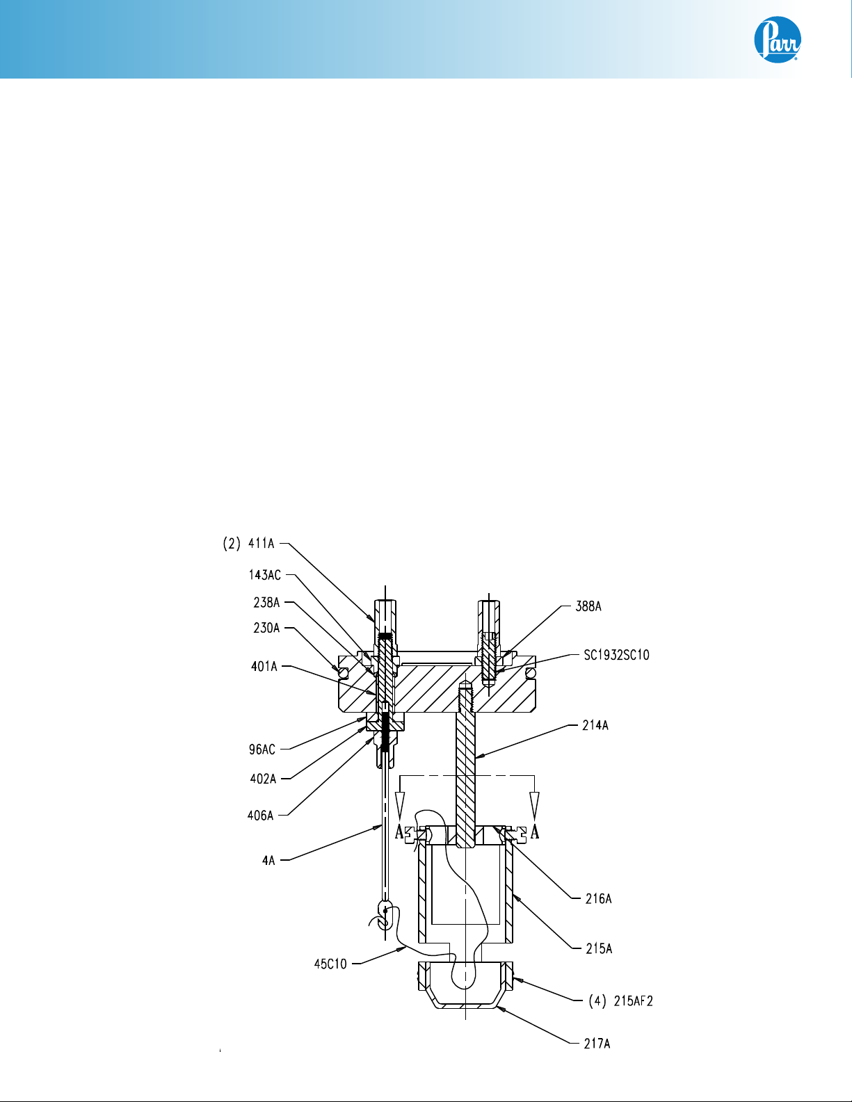
Head Assembly (Electrodes) Head Assembly (Valves)
Part No. Description Part No. Description
411A Terminal Nut
143AC Insulator 83A Valve Nut
238A O-Ring Gasket 209A Inlet Valve Body
230A Sealing Ring 13A2 Nut
401A Sleeve Insulator 84A3 Valve Spring
96AC Ceramic Washer 238A O-Ring Gasket
402A Electrode Core 109A Gasket
406A Lock Nut A11A2 Valve Stem
4A Straight Electrode 211A Valve Cover
388A Spacer
SC1932SC10 Socket Head Set Screw
Cage
214A Rod, Cage Support 397A Compression Nut
216A Disc, Cage Support 396A Outlet Valve Body
215AF1 Screw, Long 7VBCM Washer, Monel
215A Cage Tube 238A O-Ring Gasket
215AF2 Screw, Short 378A Packing Cup
217A Combustion Capsule, Heavy 20VB Valve Seat, Kel F
Loop Electrode
234A Bushing for 5A3 206A5 Bomb Head
235A Lock Nut 210A2 Outlet Valve Body
5A3 Loop Electrode 211A Valve Cover
43AS Capsule, SS
Gas Fill - Check Valve
Gas Release - Needle Valve
A420A Valve Needle
109A Gasket
8
Parr Instrument Company
Page 9

Drawings
1104 Oxygen Combustion Vessel
1104 Oxygen Combustion Vessel
212A2 REF
COMPRESSION RING
A206A5
HEAD ASSEMBLY
A208A
SCREW CAP REF
207A CYLINDER
www.parrinst.com
9
Page 10

1104 Oxygen Combustion Vessel
1104 Oxygen Combustion Vessel - Head Assembly
10
Parr Instrument Company
Page 11

1104 Oxygen Combustion Vessel
Oxygen Filling Connection for the 1104 Oxygen Combustion Vessel
www.parrinst.com
11
Page 12

Revision 04/04/13
 Loading...