

Parkside PMNF 1350 C3 Original Instructions Manual

WALL CHASER PMNF 1350 C3
WALL CHASER
Translation of the original instructions
IAN 291805
MAUERNUTFRÄSE
Originalbetriebsanleitung

Before reading, unfold the page containing the illustrations and familiarise yourself with all
functions of the device.
Klappen Sie vor dem Lesen die Seite mit den Abbildungen aus und machen Sie sich anschließend
mit allen Funktionen des Gerätes vertraut.
GB / IE / NI Translation of the original instructions Page
DE / AT / CH Originalbetriebsanleitung Seite
4
20
18
1 2
3
9
4
5
6
7
8
10
13
12
5
6
9
16
17
15
14
11

GB IE NI
Content
Introduction ................................. 4
Intended purpose .........................4
General description ......................5
Extent of the delivery ........................5
Functional description .......................5
Overview ........................................5
Technical data ..............................5
Notes on safety............................6
Symbols and icons ...........................6
General Safety Directions for Power
Tools ..............................................7
Safety instructions for cutting .............9
Additional safety instructions for all
applications ...............................10
Kickback and corresponding pre-
cautions ..................................... 10
Additional safety information ...........12
RESIDUAL RISKS ......................12
Assembly ................................... 12
Installing/changing disc .................12
Setting the groove depth .................13
Vacuuming ....................................13
Operation ..................................13
Turning on and off ..........................14
Handling ......................................15
Cleaning .......................................15
Storage ...................................... 15
Waste disposal and environmental
protection .................................. 15
Troubleshooting .........................16
Guarantee .................................17
Repair Service ............................18
Service-Center ............................ 18
Importer ....................................18
Replacement parts / Accessories 19
Original EG-Konformitäts-
erklärung ..................................39
Introduction
Congratulations on the purchase of your
new device. With it, you have chosen a
high quality product.
During production, this equipment has
been checked for quality and subjected to
a nal inspection. The functionality of your
equipment is therefore guaranteed.
The operating instructions constitute part of
this product. They contain important information on safety, use and disposal.
Before using the product, familiarise yourself with all of the operating and safety
instructions. Use the product only as de-
scribed and for the applications specied.
Keep this manual safely and in the event
that the product is passed on, hand over
all documents to the third party.
Intended purpose
The wall chaser is a tool for cutting mainly
mineral-based materials (such as concrete
or brick) without requiring the use of water.
This tool should only be used with diamond
cutting disks.
The tool should not be used in any other
application (e.g. cutting with coolant solutions, cutting harmful substances such as
asbestos).
The device is intended to be used by do-ityourselfers. It was not designed for heavy
commercial use. The tool is to be used by
adults. Children over the age of 16 may
not use the tool except under supervision.
The manufacturer is not liable for damages
caused by an improper use or incorrect
operation of this device.
4

NIIEGB
General description
See the fold-out pages for
illustrations.
Extent of the delivery
Carefully unpack the appliance and check
that it is complete. Dispose of the packaging material correctly.
- Device
- Protective hood
- 2 cutting disks (pre-mounted)
- Vacuum adapter (pre-mounted)
- Reducing adapter for vacuum
- Chuck key
- Hand chisel
- Instructions for use
Functional description
The wall chaser cuts two grooves in brickwork using two parallel diamond cutting
disks, without requiring the use of water.
Cabling grooves can be opened up by
removing the material in between the
grooves.
Please refer to the information from the
disc manufacturer.
Please refer to the descriptions below for
information about the operating devices.
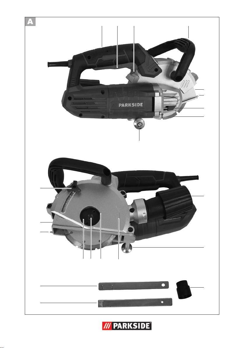
Overview
1 Handgrip
2 On/off switch
3 Switch block
4 Auxiliary handle
5 Maintenance coverage
6 Marking
7 Spindle stop button
8 Cutting disc
9 Start roller
10 Vacuum connector
11 Vacuum adapter
12 Hand chisel
13 Chuck key
14 Rotational direction marking
15 Protective guard opening
16 Mounting spindle
17 Threaded clamping ange
18 Retaining screw
19 Mounting ange
20 Spacer disks
21 Flange
Technical data
Wall chaser PMNF 1350 C3:
Rated input voltage
............................. 220 - 230 V~, 50 Hz
Power input ............................. 1350 W
Idling speed (n) .......................9000 min
Dimension of the cutting discs
............................... Ø 125 x 22,23 mm
Groove depth ........................ 0 - 30 mm
Groove width ............... 8 mm bis 26 mm
Spindle thread ................................ M14
Safety class ..........
II (Double insulation)
Protection category..........................IP X0
Sound pressure level
(L
) ......................90 dB(A); KpA= 3 dB
pA
Sound power level (L
measured ........... 101 dB(A); K
Vibration (a
) ....... 5,37 m/s2 K= 1,5 m/s
h
WA
)
WA
The vibration values represent maximum values which have been determined with the supplied blade. The actual vibration values may
vary depending on the used accessories.
The vibration values are still affected by the
handling for the user‘s.
-1
= 3 dB
2
5
GB IE NI
Cutting disc (included):
Idling speed n
0
................................... max.12250 min
Disc speed ....................... max. 80 m/s*
Outer diameter ................... Ø 125 mm
Bore hole ........................ Ø 22,23 mm
*
The grinding disc must keep a rotational
speed of 80 m/s.
Levels of noise and vibration were determined according to the norms and regulations
in the declaration of conformity.
The vibration emission value has been measured according to a standardised testing
method and may be used for comparison
with another electric tool.
The indicated vibration emission value may
also be used for an introductory assessment
of the exposure.
Warning:
The vibration emission value whilst
actually using the electrical tool may
vary from the given values independently of the type and way in which
the electric tool is used.
Try to keep the exposure to vibrations as low as possible. Examples
of measures to reduce vibration
exposure are the wearing of gloves
when using the tool and limiting the
working hours. For this purpose all
parts of the operating cycle have to
be considered (for example, times
when the electric tool is switched off
and times when it is switched on but
running without any load).
measures for the prevention of electric
shocks and the risk of injury and re.
-1
Please read all these instructions before using this electric tool and please
keep the safety instructions.
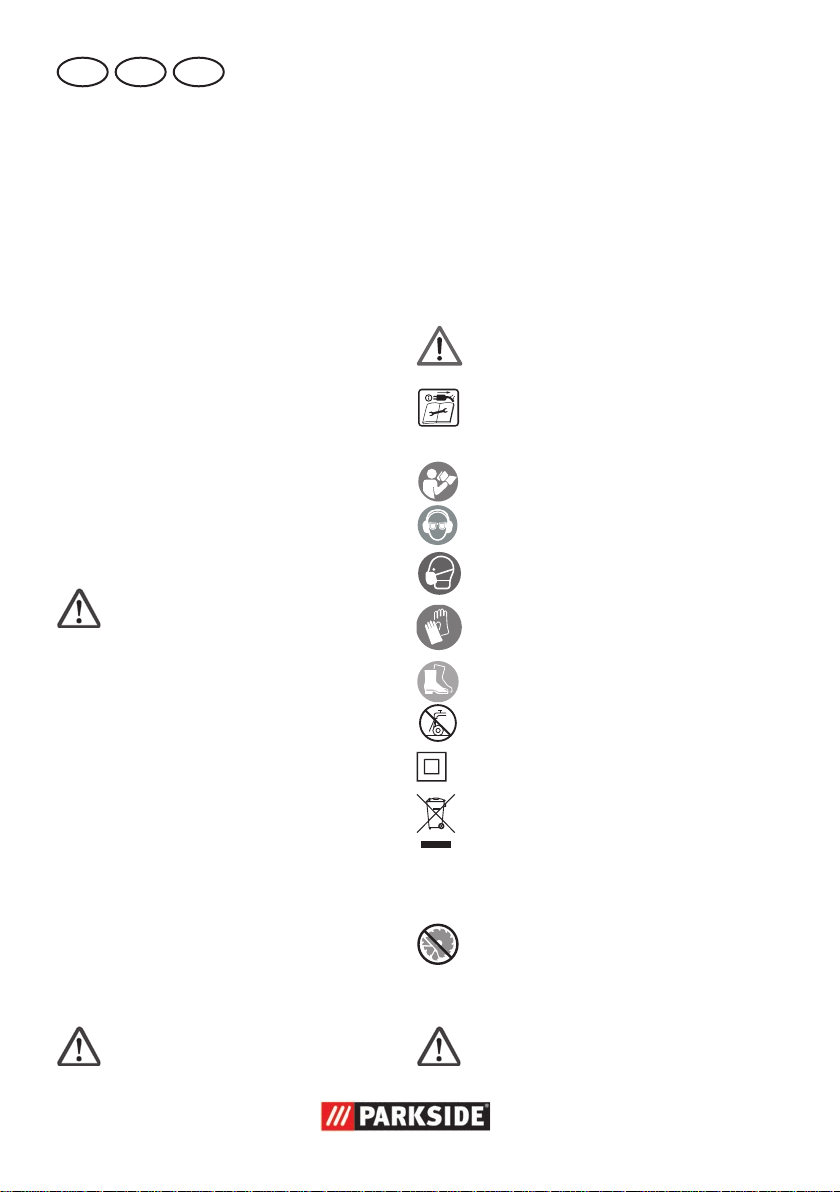
Symbols and icons
Symbols on the device:
Warning!
Warning! Electric shock hazard.
Always unplug the device before
working on it.
Read the manual!
Wear eye and ear protection.
Wear breathing protection.
Risk of cuts!
Wear cut-resistant gloves.
Wear safety shoes.
Do not use for wet grinding.
Safety class II (Double insulation).
Electrical machines do not belong
with domestic waste.
Other symbols on the
cutting disc:
Do not use defective discs.
Notes on safety
Caution! When using power tools,
observe the following basic safety
6
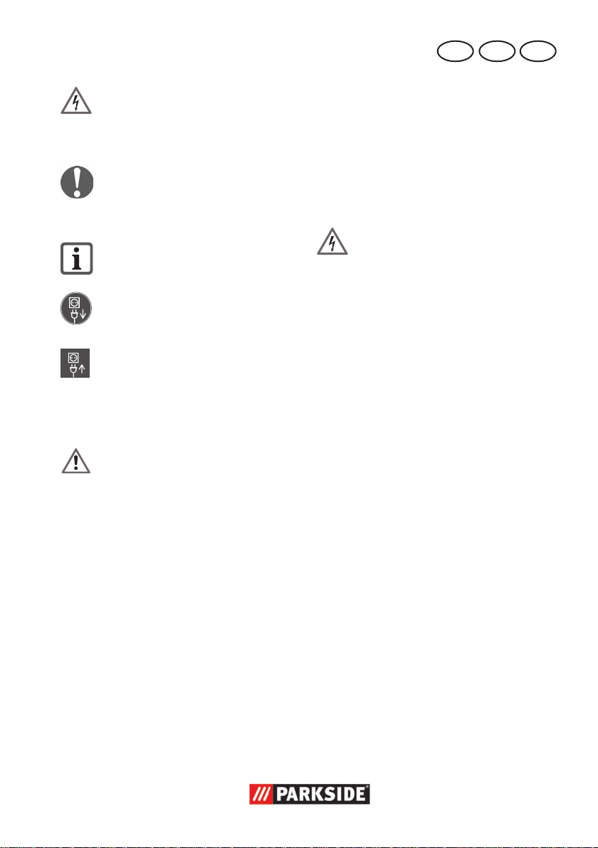
Symbols used in the instructions:
Hazard symbols with informa-
tion on prevention of personal
injury and property damage
.
NIIEGB
Hazard symbol with infor-
mation on the prevention of
personal injury caused by
electric shock.
Precaution symbol (explanation of
precaution instead of exclamation
mark) with information on prevention of harm / damage.
Notice symbol with information on
how to handle the device properly.
Switch the device off and remove
the mains plug. Allow the device to
cool down.
Connect the machine to the power
supply.
General Safety Directions for
Power Tools
WARNING! READ ALL SAFETY
DIRECTIONS AND INSTRUCTIONS. Omissions in the compliance
with safety directions and instructions
can cause electrical shock, re and/
or severe injuries.
Retain all safety directions and instructions for future use.
The term „power tool“ in the warnings refers
to your mains-operated (corded) power tool
or battery-operated (cordless) power tool).
Work area safety :
• Keep work area clean and well lit.
Cluttered or dark areas invite accidents.
• Do not operate power tools in
explosive atmospheres, such as in
the presence of ammable Iiquids,
gases or dust. Power tools create
sparks which may ignite the dust or fumes.
• Keep children and bystanders
away while operating a power
tool. Distractions can cause you to lose
control.
Electrical safety :
CAUTION! The following states how
to avoid accidents and injuries due to
electric shock:
• Power tool plugs must match the
outlet. Never modify the plug in
any way. Do not use any adapter plugs with earthed (grounded) power tools. Unmodied plugs
and matching outlets will reduce risk of
electric shock
• Avoid body contact with earthed
or grounded surfaces, such as
pipes, radiators, ranges and refrigerators. There is an increased risk
of electric shock if your body is earthed
or grounded.
• Do not expose power tools to
rain or wet conditions. Water entering a power tool will increase the risk
of electric shock.
• Do not abuse the cord. Never
use the cord for carrying, pulling
or unplugging the power tool.
Keep cord away from heat, oil,
sharp edges or moving parts.
Damaged or entangled cords increase
the risk of electric shock.
• When operating a power tool
outdoors, use an extension cord
suitable for outdoor use. Use of a
cord suitable for outdoor use reduces
the risk of electric shock.
7

GB IE NI
• If operating a power tool in a
damp location is unavoidable,
use a residual current device
(RCD) protected supply. Use of an
RCD reduces the risk of electric shock.
Use a circuit breaker with a current limit
of 30 mA or less.
Personal safety:
CAUTION! The following states how
to avoid accidents and injuries:
• Stay alert, watch what you are
doing and use common sense
when operating a power tool.
Do not use a power tool while
you are tired or under the inuence of drugs, alcohol or medication. A moment of inattention white
operating power tools may result in
serious personal injury.
• Use personal protective equip-
ment. Always wear eye protection. Protective equipment such as dust
mask, non-skid safety shoes, hard hat, or
hearing protection used for appropriate
conditions will reduce personal injuries.
• Prevent unintentional starting.
Ensure the switch is in the offposition before connecting to
power source and/or battery
pack, picking up or carrying the
tool. Carrying power tools with your
nger on the switch or energising power tools that have the switch on invites
accidents.
• Remove any adjusting key or
wrench before turning the power tool on. A wrench or a key left
attached to a rotating part of the power
tool may result in personal injury.
• Do not overreach. Keep proper
footing and balance at all times.
This enables better control of the power
tool in unexpected situations.
• Dress properly. Do not wear
loose clothing or jewellery. Keep
your hair, clothing and gloves
away from moving parts. Loose
clothes, jewellery or long hair can be
caught in moving parts.
• If devices are provided for the
connection of dust extraction
and collection facilities, ensure
these are connected and properly used. Use of dust collection can
reduce dust-related hazards.
Power tool use and care :
• Do not force the power tool. Use
the correct power tool for your
application. The correct power tool
will do the job better and safer at the
rate for which it was designed.
• Do not use the power tool if the
switch does not turn it on and
off. Any power tool that cannot be
controlled with the switch is dangerous
and must be repaired.
• Disconnect the plug from the po-
wer source and/or the battery
pack from the power tool before making any adjust -ments,
changing accessories, or storing
power tools. Such preventive safety
measures reduce the risk of starting the
power tool accidentaIly.
• Store idle power tools out of the
reach of children and do not allow persons unfamiliar with the
power tool or these instructions
to operate the power tool. Power
tools are dangerous in the hands of untrained users.
• Maintain power tools. Check
for misalignment or binding
8

NIIEGB
of moving parts, breakage of
parts and any other condition
that may affect the power tool’s
operation. If damaged, have the
power tool repaired before use.
Many accidents are caused by poorly
maintained power tools.
• Keep cutting tools sharp and
clean. Properly maintained cutting
tools with sharp cutting edges are less
Iikely to bind and are easier to control.
• Use the power tool, accessories
and tool bits etc. in accordance
with these instructions, taking
into account the working conditions and the work to be performed. Use of the power tool for
operations different from those intended
could result in a hazardous situation.
Service:
• Have your power tool serviced
by a qualied repair person
using only identical replacement
parts. This will ensure that the safety
of the power tool is maintained.
Safety instructions for
cutting
a) The protective guard on the de-
vice must be securely fastened,
and adjusted to ensure maximum safety, i.e. the smallest
possible section of the abrasive
surface should be visible to the
user. Ensure that you and all
persons in the vicinity keep out
of the plane of the rotating disk.
The protective guard is designed to
protect users from ying debris and
accidental contact with the abrasive
surface.
b) Only use diamond cutting disks
with this tool. Attaching the accessories to the device does not guarantee
safe operation.
c) The allowable rotation speed
of the attachment tools must be
at least as high as the highest
rotation speed indicated on the
electric tool. Accessories that run fas-
ter than the allowable speed can break
and y apart.
d) Schleifkörper dürfen nur für die
empfohlenen Einsatzmöglichkeiten verwendet werden. Zum
Beispiel: Schleifen Sie nie mit der
Seitenäche einer Trennscheibe.
Trennscheiben sind zum Materialabtrag
mit der Kante der Scheibe bestimmt.
Seitliche Krafteinwirkung auf diese
Schleifkörper kann sie zerbrechen.
e) Verwenden Sie immer unbeschä-
digte Spannansche in der richtigen Größe und Form für die von
Ihnen gewählte Schleifscheibe.
Geeignete Flansche stützen die Schleifscheibe und verringern so die Gefahr
eines Schleifscheibenbruchs.
f) Außendurchmesser und Dicke
des Einsatzwerkzeugs müssen
den Maßangaben Ihres Elektrowerkzeugs entsprechen. Falsch
bemessene Einsatzwerkzeuge können
nicht ausreichend abgeschirmt oder
kontrolliert werden.
g) The cutting disks and anges
must t the grinding spindle precisely. Disks that do not t the grin-
ding spindle precisely rotate unevenly,
vibrate sharply and can lead to loss of
control.
h) Never use damaged attachment
tools. Check attachment tools
such as grinding discs for chipping or cracks, grinding plates
9

GB IE NI
for cracks, wear or strong abrasion and wire brushes for loose
or broken wires before using
them. If the electric tool or the
attachment tool falls off, check
whether it is damaged or, use
an undamaged attachment tool.
If you have checked the attachment tool and attached it, keep
yourself and any nearby persons
beyond the level of the rotating
attachment tool and allow the device to run for 1 min. at the highest rotational speed. Damaged tools
usually break during this test period.
i) Wear personal safety equip-
ment. Depending on the application, use full face shields, eye
protection or safety goggles. In
so far as it is appropriate, wear
dust masks, ear protection,
gloves or special aprons which
keep small grinding and material particles away from you. Eyes
should be protected from the foreign
matter which can be caused to y during the various applications. Dust or
breathing masks should lter the dust
that is created during operation. If you
are exposed to loud noise for a long
time, you may suffer hearing loss.
j) Ensure that other people are at
a safe distance to your working
area. Anyone who enters the working area should wear personal
protective equipment. Broken bits from
the piece being worked or broken attach-
ment tools can y away and cause injuries
even beyond the direct working area.
k) Hold the electric tool only by the
insulated gripping surfaces when
performing work in which the
cutting tool may come into contact
with hidden wiring or its own
cord. Contact with a live wire can also
cause a charge in metal parts of the
device and result in an electric shock.
l) Keep the cord away from the ro-
tating attachment tool. If you lose
control of the device, the power cord
can become separated or caught and
your hand or arm may be pulled into
the rotating attachment tool.
m) Never put the electric tool down
before the attachment tool has
come to a full stop. The rotating at-
tachment tool can come into contact with
the surface upon which it is set, whereby
you could lose control of the electric tool.
n) Never allow the electric tool to
run while you are carrying it.
Your clothing may accidentally come
into contact with the rotating attachment
tool and get caught and the attachment
tool could drill into your body.
o) Clean the ventilation slots of
your electric tool routinely. The
motor air pulls dust into the housing
and, should too much metallic dust collect, could cause electrical hazards.
p) Never use the electric tool near
ammable material. Sparks could
ignite this material.
q) Do not use attachment tools
which require liquid coolant.
Using water or another liquid coolant
could lead to electrical shock.
Additional safety instructions
for all applications
Kickback and corresponding
precautions
Kickback is the sudden reaction from a
chopping or blocked grinder attachment
1 0

NIIEGB
such as a grinding disc, grinding plate,
wire brush etc. Chopping or blocking leads
to sudden stopping of the rotating attachment. This causes an uncontrolled electric
tool to accelerate in a direction counter to
the rotational direction of the attachment
tool. If, for example, a grinding disc cuts
into the workpiece or blocks it, the edge of
the grinding disc that digs into the workpiece can get caught and, through that,
break off the grinding disc or cause a kickback. The grinding disc then moves towards
or away from the operator, depending on
the direction of rotation of the disc at the
blocked spot. Here, the grinding discs can
also break. A kickback is caused by wrongly or incorrectly operating the electric tool.
It can be avoided by suitable cautionary
measures, such as described below.
a) Hold the electric tool very rmly and
bring your body and your arm into a
position in which you can resist the kickback force. Always use the supplemental
handle if available to give you the best
control over kickback force or reaction
time during acceleration. The operator
can master the kickback and reaction
force through suitable precautions.
b) Never bring your hands near a rotating
attachment tool. The attachment tool
can run over your hand in the kickback.
c) Keep your body away from the area
in which the electric tool would move
during a kickback. The kickback drives
the electric tool in the counter-direction
to the rotation of the grinding disc at
the blocked spot.
d) Work particularly cautiously in corner
areas or where there are sharp corners etc. Prevent the attachment tools
from recoiling from the workpiece and
jamming. The rotating attachment tool
tends to jam when near corners, sharp
edges or when it recoils from such. This
causes a loss of control or kickback.
e) Do not use chain or toothed saw bla-
des. Such attachment tools frequently
cause a kickback or loss of control over
the electric tool.
f) Avoid blocking the cutting disc or pres-
sing down too hard. Do not make any
excessively deep cuts. Overloading the
cutting disc increases wear and its tendency to tilt or block and, with that, to
kickback or break the grinder.
g) If the cutting disc jams, or you interrupt
your work, switch the device off and
hold it until the disc has come to a full
stop. Never try to pull the cutting disc
out of the cut while it is still running,
because it can kick back. Identify and
correct the cause of the jamming.
h) Do not switch the electric tool on again
as long as it is in the workpiece. Allow
the cutting disc to rst reach its full
rotational speed before you carefully
resume with the cutting. Otherwise, the
disc may catch, spring away from the
workpiece or cause a kickback.
i) Support plates or workpieces to reduce
the risk of kickback from a jammed cutting disc. Large workpieces may bend
under their own weight. The workpiece
must be supported on both sides of the
disc, near the cutting disc as well as
also at the edge.
j) Be particularly careful for pocket cuts in
existing walls or other areas where you
cannot see what is there. The cutting
disc may cause a kickback when it cuts
into gas or water lines, electrical lines
or other hidden objects.
1 1
GB IE NI
Additional safety information
a) Approved cutting disk types:
segmented diamond disks with a
maximum space of 10 mm between
segments, only with a negative cutting
angle.
Disk diameter: 125 mm
Disk thickness: 2,1 mm
RESIDUAL RISKS
Even if properly operating and handling
this electric tool, some residual risks will
remain. Due to its construction and build,
this electric tool may present the following
hazards:
a) Lung damage if suitable respiratory pro-
tection is not worn.
b) Hearing damage if suitable ear protec-
tion is not worn.
c) Damage to health due to
- touching the area of the grinding tool
which is not covered;
- ejection of parts of workpieces or
damaged grinding discs.
d) Health injuries which result from swin-
ging hand and arm, in the event that
the device is used over a longer period
of time or is not used and maintained
properly.
Warning! During operation, this
electric tool generates an electro-
magnetic eld which, under certain
circumstances, may impair the functionality of active or passive medical
implants. To reduce the risk of serious or lethal injuries, we recommend
that persons with medical implants
consult their doctor and the manufacturer of their medical implant
before operating the machine.
Assembly
Caution! Risk of injury!
- Ensure that you have sufcient
space in which to work, and that
you do not endanger other people.
- All hoods and protective devices
must be assembled properly before commissioning.
-
Installing/changing disc
1. Press the spindle stop button (7).
2. Turn the mounting spindle (16)
3. Release the clamping nut
(17) with the chuck key
(13). You can release the spindle
4. Remove the threaded clamping
5. Remove the cutting disk (8) by
6. Remove the ange (21) and the
7. Remove the second cutting disk
8. The take-up ange (19) can be
If you remove the take-up ange
Disconnect the mains plug before
changing the setting on the
device.
until the spindle lock xed the
mounting spindle. Keep and continue to hold down the spindle
lock button (7).
lock button (7.
ange (17) through the opening
in the protective guard (15).
lifting and pulling away the takeup spindle (16) until it reaches
the protective guard.
spacer disks (20) through the
opening in the protective guard
(15).
(8) as described in point 5.
left on the take-up spindle (16).
(19), make sure to position it cor-
1 2

NIIEGB
rectly. The take-up ange‘s (19)
contouring must face towards
the motor. If you turn the take-up
ange (19), the take-up spindle
(16) must turn with it.
9. Position the desired cutting disk
(8) on the take-up ange (19).
The label on the disc should always face the device.
10. Set the desired cutting width by
selecting the spacer disks (20).
Push the spacer disks onto the
take-up spindle (16). This is fol-
lowed by the ange (21). This is
followed by the second cutting
disk (8). All separator disks (20)
not used for setting the cutting
width must be pushed onto the
take-up spindle (16) after the
second cutting disk.
11. Reposition the threaded clam-
ping ange (17) on the take-up
spindle (16).
12. Press the spindle retaining tab
(7), and turn the take-up spindle
(16) until the spindle retainer
xes the take-up spindle (16).
Retighten the threaded clamping
ange (17) using the chuck key
(13). You can now release the
spindle retaining tab (7).
Setting the groove depth
1. Release the retaining screw (18).
2. Set the depth-stop to the required
depth. Adjust the protective
guard (5) to do this.
3. Reattach the protective guard (5)
with the retaining screw (18).
Vacuuming
During operation, the wall chaser generates a large quantity of dust. You should
therefore wear a dust mask, and always
connect an industrial vacuum cleaner.
If the vacuum system malfunctions, pause
operation and clear the malfunction!
Attaching the vacuum cleaner
Unscrew the suction connector (10) cap.
Insert the industrial vacuum cleaner’s hose
through the cap and screw the cap tight.
If your vacuum cleaner’s hose is the wrong
diameter for a direct connection, you can
insert the vacuum adapter (11) in between
with a single turn.
Always attach a vacuum cleaner. Damage
to the motor caused by failure to attach
a vacuum cleaner is not covered by the
warranty.
Operation
Caution! Risk of injury!
- Always remove the mains plug
before working on the tool.
- Only use grinding discs and accessories recommended by the manufacturer. Using other attachment
tools and other accessories can
represent a risk of injury for you.
- Only use grinding tools which
bear information about the
manufacturer, type of binding,
dimension and permitted number
of revolutions.
- Only use grinding discs where
the printed rotational speed is at
1 3
GB IE NI
least as high as what has been
specied on the name plate of
the device.
- Do not use any broken, cracked,
or otherwise damaged grinding
discs.
- Never operate the device without protective equipment.
- Support the plates or workpieces
in order to reduce the risk of
kickback from a jammed cutting
disc. Large workpieces may
bend under their own weight.
The workpiece must be supported on both sides of the disc, not
only near the cutting disc, but
also at the edge.
Keep your hands away from
the disc when the device is in
operation. Risk of injury.
Information on replacement:
• Never operate the device
without protective equipment.
• Ensure that the rotation speed stated on the grinding disc (8) is the
same or higher than the nominal
rotation speed of the device.
•
• Only use awless grinding discs
• Never re-drill a locating hole which
• Never use separate bushings or
• Do not use any saw blades.
Ensure that the grinding disc dimensions match those of the device.
(ringing test: when you strike the
grinding disc with a plastic hammer, it results in a clear sound).
is too small to make it larger.
adapters in order to make grinding discs with a hole that is too
large t the device.
Only replace the diamond
cutting disks in pairs.
Switch the device off and remove
the mains plug. Allow the device to
cool down.
Wear protective gloves when changing the discs in order to avoid cutting damages.
Turning on and off
Make sure that the power supply
voltage matches the voltage rating
indicated on the device‘s type plate.
Connect the machine to the power
supply.
1. To start the device, push the switch
lock (3) forwards. Press the on/off
switch (2).
2. To turn it off, release the on-off button.
The device turns off.
After switching on the device, wait until the
device has reached its max. speed. Only
then should you start with the work.
The disc still runs even after
the device has been switched
off. Risk of injury.
Trial run:
Always carry out a trial run before carry-
ing out your rst grinding procedure and
after every disc replacement. Switch the
device off immediately if the grinding disc
is not rotating smoothly, if considerable
vibration occurs or if you hear abnormal
noises.
1 4
 Loading...