

Page 1
PNEUMATIC STAPLER PDT 40 B2
PNEUMATIC STAPLER
Operation and Safety Notes
Translation of original operation manual
ŽEBLJALNIK NA STISNJEN ZRAK
Navodila za upravljanje in varnostna opozorila
Prevod originalnega navodila za uporabo
PNEUMATICKÝ SPONKOV AČ
Pokyny pre obsluhu a bezpečnostné pokyny
Preklad originálneho návodu na obsluhu
IAN 73782
ZSZYWACZ CIŚNIENIOWY
Wskazówki dotyczące obsługi i bezpieczeństwa
Tłumaczenie oryginalnej instrukcji obsługi
PNEUMATICKÁ SPONKOV AČKA
Pokyny pro obsluhu a bezpečnostní pokyny
Překlad originálního provozního návodu
DRUCKLUFT-TACKER
Bedienungs- und Sicherheitshinweise
Originalbetriebsanleitung
Page 2

Before reading, unfold both pages containing illustrations and familiarise yourself with all functions of the
device.
Przed przeczytaniem proszę rozłożyć obie strony z ilustracjami, a następnie proszę zapoznać się z wszystkimi funkcjami urządzenia.
Pred branjem obe strani s slikami odprite navzven in se nato seznanite z vsemi funkcijami naprave.
Před čtením si odklopte obě dvě strany s obrázky a potom se seznamte se všemi funkcemi přístroje.
Pred čítaním si odklopte obidve strany s obrázkami a potom sa oboznámte so všetkými funkciami prístroja.
Klappen Sie vor dem Lesen die beiden Seiten mit den Abbildungen aus und machen Sie sich anschließend
mit allen Funktionen des Gerätes vertraut.
GB Operation and Safety Notes Page 5
PL Wskazówki dotyczące obsługi i bezpieczeństwa Strona 13
SI Navodila za upravljanje in varnostna opozorila Stran 23
CZ Pokyny pro obsluhu a bezpečnostní pokyny Strana 33
SK Pokyny pre obsluhu a bezpečnostné pokyny Strana 41
DE / AT / CH Bedienungs- und Sicherheitshinweise Seite 49
Page 3

11
10
1 2 3 4
A
9
8
7
56
12
Page 4
B
C
D
Page 5

Table of contents
Introduction
Intended use ........................................................................................................................................ Page 6
Features and fittings ............................................................................................................................ Page 6
Included items .....................................................................................................................................Page 6
Technical data ..................................................................................................................................... Page 6
Safety of the fastener driving tool ............................................................................Page 7
Work safety ......................................................................................................................................... Page 8
Additional safety information for compressed air tackers ................................................................ Page 8
Original accessories / tools ................................................................................................................ Page 9
Preparing the product for use
Connecting the compressed air source .............................................................................................Page 9
Loading the magazine ........................................................................................................................ Page 9
Operation .......................................................................................................................................Page 9
Removing jammed fasteners ............................................................................................................... Page 10
Maintenance and cleaning
Maintenance ....................................................................................................................................... Page 10
Cleaning .............................................................................................................................................. Page 11
Service ............................................................................................................................................... Page 11
Warranty ......................................................................................................................................... Page 11
Disposal ............................................................................................................................................ Page 11
Declaration of Conformity / Manufacturer..........................................................Page 12
5 GB
Page 6

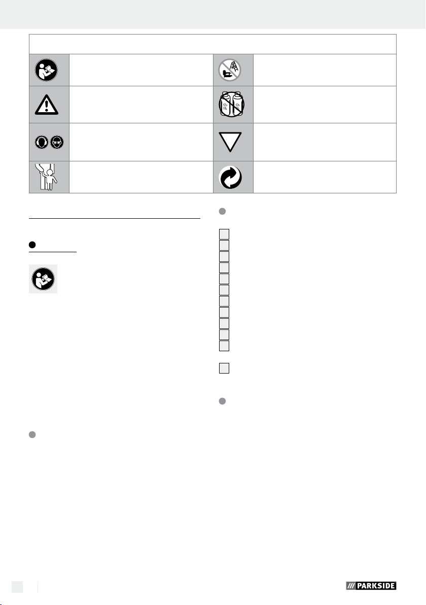
The following pictograms are used in these operating instructions / on the device:
Read instruction manual!
Observe caution and safety notes!
Wear hearing protection
and protective glasses.
Keep children away from electrical
devices!
Pneumatic stapler PDT 40 B2
Introduction
We congratulate you on the purchase of
your new device. You have chosen a high
quality product. The operating instructions
are part of the product. They contain important information concerning safety, use and disposal. Before using the product, familiarise yourself with all
of the operating instructions and safety instructions.
Use the product only as described and for the
specified applications. If you pass the product on
to anyone else, please ensure that you also pass
on all the documentation with it.
Intended use
The device is suitable for assembly and repair work.
Any other use or modification to the device shall be
considered as improper use and could give rise to
considerable dangers. We will not accept liability
for loss or damage arising from improper use. The
device is intended for private domestic use only.
Features and fittings
1
Exhaust air aperture (can be rotated)
2
Trigger
3
Handle
6 GB
Do not use the device on scaffolds
or ladders.
Never use hydrogen, oxygen, carbon
dioxide or other bottled gases as an
energy source.
Trigger lock
Dispose of packaging and
device in an environmentally-friendly
way!
4
Threaded nipple 6.35 mm (¼“)
5
Magazine
6
Fill level indicator
7
Knurled screw
8
Trigger lock
9
Mouth
10
Face plate
11
Face plate quick clamp lever
12
Magazine lever
Included items
1 Pneumatic stapler PDT 40 B2
1 Carrying case
1 Special compressed air oil
1 Threaded nipple 6.35 mm (¼“) (pre-assembled)
1 Package nails, 1000 pcs.
1 Package staples, 1000 pcs.
1 Protective glasses
1 Operating instructions
Technical data
Dimensions: 248 x 58 x 246 mm
(L x H x W)
Weight
(without fasteners): 1.513 kg
Trigger type: Compressed air
Maximum permissible
pressure: 8 bar
Page 7
Introduction / Safety of the fastener driving tool
Recommended pressure
range: 4 to 7.5 bar
Air consumption per
drive in process: approx. 0.13 litre per
driving-in process
Recommended lubricant:
Compressed air special oil
Loading capacity: 100 pcs.
Nail lengths: 15 mm, 20 mm
25 mm, 30 mm,
32 mm, 35 mm,
38 mm, 40 mm,
45 mm, 50 mm,
Staple lengths: 10–40 mm
Staple width: 5.7 mm
Recommended
Hose diameter: ∅ 9 mm
Compressed air quality: Cleaned, oil-misted
and condensate-free
Noise and vibration data:
Measured values for noise are determined in accordance with EN 12549:1999, EN ISO 4871.
The A-weighted sound pressure level of the device is
typically 90.6 dB (A). Uncertainty K = 3 dB. The
sound level while working can exceed 103.6 dB (A).
These values are characteristic values referenced to
the device and do not reflect noise development at
the work location. Noise development at the work
location depends e.g. on the work environment, the
workpiece, the workpiece support and the number
of fastener driving processes.
In correspondence with conditions at the work location, individual noise reduction measures may need
to be carried out, such as placing the workpiece on
a noise-suppressing surface, clamping or covering
to prevent workpiece vibration and adjusting to the
minimum pressure required by the work process. In
certain cases, wearing personal hearing protection
is require.
Wear hearing protection!
Vibration values in accordance with
ISO 8662-11:1999:
Vibration emission value a
Uncertainty K = 1.5 m / s
= 12.380 m / s
h,D
2
2
Mechanical impact (vibration)
The vibration value for the fastener driving device was
determined in accordance with ISO 8662-11:1999 —
Hand-held portable power tools – Measurement of
vibrations at the handle — Fastener driving tools
(see technical data). The value is referenced to the
device and does not represent the influence on the
hand-arm system when the device is used. Influence
on the hand-arm system when using the device depends on e.g. gripping force, pressing force, working direction, air pressure set, the workpiece and its
position.
Safety of the fastener
driving tool
Please read all the safety
information and instructions. Failure to com-
ply with the safety instructions and instructions can
result in severe injuries and / or damage to pro
PLEASE RETAIN ALL SAFETY INFORMATION
AND INSTRUCTIONS FOR FUTURE REFERENCE.
Each time before starting work, check
for flawless functioning of the safety
and triggering devices as well as the
firm fit of all bolts and nuts.
Do not conduct any improper manipu-
lation of the fastener driving tool.
Do not dismount or block any part of
the fastener driving tool, such a trigger lock.
Do not conduct any „emergency re-
pairs“ with unsuitable materials.
The fastener driving tool must be reg-
ularly and properly maintained as
specified by the manufacturer.
Prevent anything that would weaken
or damage the device, e.g. by:
– stamping or engraving,
perty.
7 GB
Page 8
– alterations not permitted by the
manufacturer,
– guiding on templates made of hard
material, e.g. steel,
– permitting to fall onto or slide across
the floor,
– using as a hammer,
– every type of external force.
Work safety
Never point a fastener driving tool that
is ready to use directly at yourself,
other persons or animals.
During work, hold the fastener driving
tool so that head and body can not be
injured by possible kickback due to a
fault in the power supply or from hard
places in the workpiece.
Never trigger the fastener driving tool
into empty space. Following this instruction
will prevent danger due to uncontrolled flying
fasteners and overloading the device.
Before transporting, disconnect the
fastener driving tool from the compressed air network, particularly when
using ladders or are moving with an
unaccustomed body posture.
At the workplace, only carry the fas-
tener driving tool by its grip and never
with the trigger actuated.
Pay attention to workplace conditions.
Fasteners may strike completely through thin
workpieces or slide off corners or edges to
cause a danger to persons.
Use suitable personal protec-
tion equipment, e.g. hearing
and eye protection. Wearing personal
protective devices such as dust mask, non-slip
safety shoes, safety helmet or hearing protectors,
depending on the type of fastener driving tool
and its application, reduces the risk of injuries.
Additional safety
information for
compressed air tackers
RISK OF INJURY! Never
exceed the maximum permissible operating
pressure of 8 bar. Use a pressure reducer to
adjust the operating pressure.
RISK OF INJURY! Never
use oxygen or other flammable gases as en-
ergy source.
Keep your working area clean and
well lit. Untidy or poorly lit working areas
can lead to accidents.
Keep children and other indi-
viduals away from the fastener driving tool during use.
Distractions can cause you to lose control of
the device.
Remain alert at all times, watch what
you are doing and always proceed
with caution when working with a
fastener driving tool. Do not use any
fastener driving tool if you are tired
or under the influence of drugs, alcohol
or medication. One moment of carelessness
when using the fastener driving tool may result
in serious injuries.
Avoid placing your body in an unnat-
ural position. Keep proper footing
and balance at all times. By doing this you
will be in a better position to control the fastener driving tool in unforeseen circumstances.
Before any repair and maintenance work or
transport, remove the device from the compressed air source.
RISK OF INJURY! Do not use the
device on scaffolds or ladders.
Never use hydrogen, oxygen, car-
bon dioxide or other bottled gasses
to power this tool as doing so may
result in an explosion and thus may cause severe injuries.
RISK OF INJURY! Do not use the device if
the trigger lock
removed. Otherwise injuries may result.
8
is damaged or has been
8 GB
Page 9
Safety of the fastener driving tool / Preparing the product for use / Operation
When loosening the hose coupling, hold the
hose firmly in your hand to prevent injuries
caused by a rebounding hose.
Be absolutely certain to use a ¼‘„ threaded
nipple and a quick-release coupling for the
compressed air connection.
Never place your hands near the mouth when
the device is ready to operate. Otherwise injuries may result.
Pay attention to damage. Check the de-
vice for damage before bringing it into use. If
the device exhibits defects, it must not be operated under any circumstances.
Do not use any pointed objects. Never
insert pointed and / or metal objects into the
inside of the device.
Original accessories / tools
Use only the accessories and attachment
detailed in the operating instructions.
The use of fasteners or other accessories other
than those recommended in the operating instructions could lead to you suffering an injury.
Preparing the product for use
1. To do so, press the compressed air hose quickrelease coupling (not included in the scope of
delivery) on the ¼“ threaded nipple
compressed air tacker.
Locking is automatic.
2. Connect the other end of the compressed air
hose to the (filter) pressure reducer on the compressor.
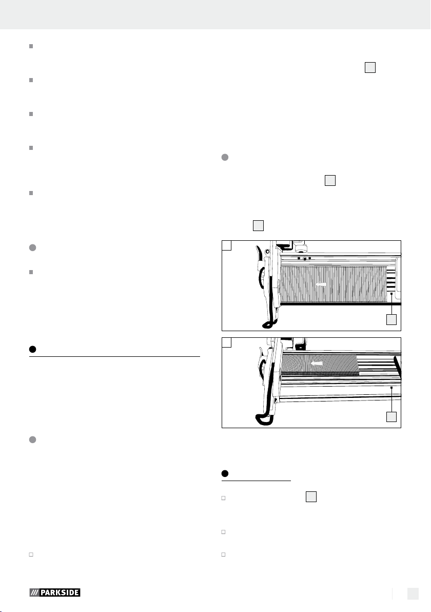
Loading the magazine
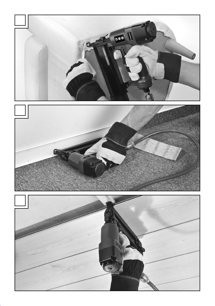
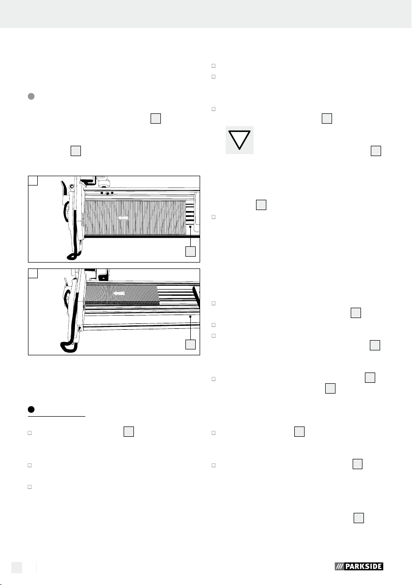
1. Press the magazine lever 12 and pull the magazine cover back to its stop position.
2. Insert the corresponding fastener (nails, see
Fig. 01 or staples, see Fig. 02) into the maga-
5
zine
.
01
s
02
4
of the
5
NOTE: always wear the protective goggles supplied before putting the tool into operation. Remove
the protective film from the protective goggles before
using for the first time.
Connecting the compressed
air source
NOTE: The compressed air tacker must only be
operated with cleaned, oil-misted compressed air
and must not exceed the maximum operating pressure of 8 bar. The compressor must be fitted with a
pressure reducer in order to regulate the operating
pressure.
Connect the device to a suitable compressed
air source.
5
3. Slide the magazine cover forwards until it locks.
Operation
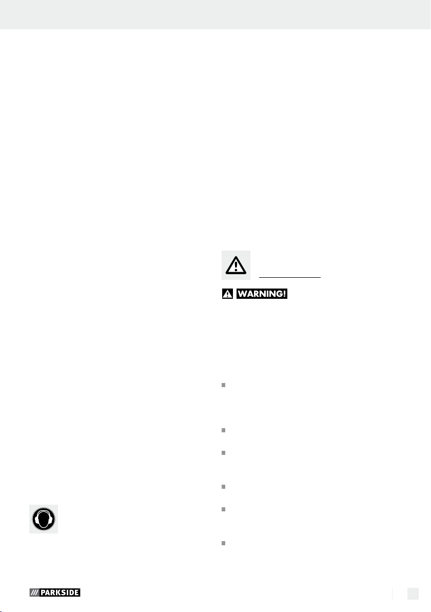
Load the magazine 5 of the compressed air
tacker as described in the chapter “Loading the
magazine“.
Use the pressure reducer to set the correct
operating pressure.
Ensure that the permissible operating pressure
of 8 bar at the device is never exceeded.
Operating pressure that is too high does not
9 GB
Page 10
provide any performance increase, but only increases compressed air consumption and ac-
celerates wear on the device.
Switch on the compressor.
Allow the compressor to run once long enough
until maximum tank pressure is reached and the
device is switched off.
Place the compressed air tacker on the workpiece
and press the trigger
2
.
NOTE: The compressed air tacker
is equipped with a trigger lock
8
The fastener will only leave the device
when the mouth of the compressed air tacker is
pressed against the workpiece and the trigger
is actuated.
Check that the fastener has been driven in cor-
responding to the work requirements.
– If the fastener is protruding, increase the air
pressure in 0.5 bar increments.
– If the fastener is too deep, decrease the air
pressure in 0.5 bar increments.
As an alternative, you can accelerate the work
by keeping the trigger
2
depressed.
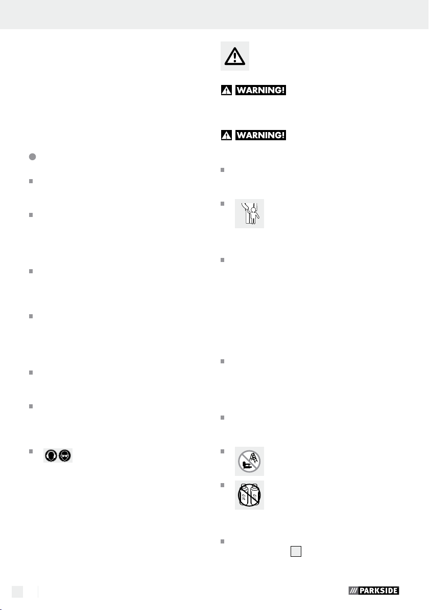
Set the compressed air tacker against the work-
piece.
Press the device against the workpiece until the
9
mouth
touches it. The fastener will leave the
device.
As long as the trigger 2 is kept depressed, each
time the mouth
9
touches the workpiece one
fastener will leave the device.
Another alternative is to keep the mouth
9
pressed against the workpiece.
Each time the trigger 2 is actuated, a fastener
will leave the device.
NOTE: Fine adjustment with the knurled screw
is possible.
Turn the knurled screw 7 downwards in order
to drive the fastener more deeply into the workpiece.
Turn the knurled screw 7 upwards in order to
drive the fastener less deeply into the workpiece.
Turn the exhaust air aperture 1 to guide the
exhaust airflow in the desired direction.
After finishing work, disconnect the device from
the compressor.
Removing jammed fasteners
If a staple or nail gets jammed in the magazine
slot, immediately disconnect the compressed
air supply.
Open the magazine 5 as described in the
.
chapter “Loading the magazine“.
Open the face plate 10 by pulling the face
plate quick clamping lever
2
of the trigger lock
11
in the direction
8
.
Remove the jammed fastener.
Close the face plate 10 by pulling the face
plate quick clamping lever
of the exhaust air aperture
11
in the direction
1
.
Close the magazine 5 of the compressed air
tacker as described in the chapter “Loading the
magazine“.
Maintenance and cleaning
RISK OF INJURY! Be absolutely certain to
disconnect the device from the compressed air
source before cleaning or maintaining it.
Maintenance
Lubrication with oil mister
NOTE: As a treatment stage after the pressure re-
ducer, an oil mister provides continuous and opti
lubrication of the compressed air tacker. An oil mister gives off fine drops of oil into the airflow and so
guarantees regular lubrication.
7
Install the oil mister after the (filter) pressure re-
ducer. To do so, insert the nipple of the oil mister into the quick-release coupling of the (filter)
pressure reducer.
Then connect the compressed air device to the
quick-release coupling provided for it.
mum
10 GB
Page 11
Maintenance and cleaning / Service / Warranty / Disposal
Manual lubrication
NOTE: If you do not have an oil mister, lubricate the
device each time after driving about 5000 fasteners.
Apply 1–2 drops of special compressed air oil
into the threaded nipple
4
of the compressed
air tacker.
Then press the trigger 2 several times.
ATTENTION: Be certain not to use too much
oil; otherwise oil could leave the mouth with the
fastener and potentially damage the workpiece.
Cleaning
Do not use any sharp objects to clean the de-
vice. Do not allow any liquids to enter the device. Otherwise the device could be damaged.
Clean the device regularly, preferably always
immediately after finishing work.
Use a dry cloth to clean the housing. Under no
circumstances should you use petrol, solvent or
cleaners which attack plastic.
After each use, pack the compressed air tacker
in the carrying case it was delivered with to
protect it from dirt.
Service
Have your fastener
driving tool repaired only by qualified
specialist personnel using original manufacturer parts only. This will ensure that
your fastener driving tool remains safe to use.
Warranty
The warranty for this appliance is for 3
years from the date of purchase. The appliance has been manufactured with care
and meticulously examined before delivery. Please retain your receipt as proof
of purchase. In the event of a warranty
claim, please make contact by telephone
with our Service Department. Only in this
way can a post-free despatch for your
goods be assured.
The warranty covers only claims for material and
maufacturing defects, but not for transport damage,
for wearing parts or for damage to fragile components, e.g. buttons or batteries. This product is for private use only and is not intended for commercial use.
The warranty is void in the case of abusive and improper handling, use of force and internal tampering not carried out by our authorized service branch.
Your statutory rights are not restricted in any way
by this warranty.
The warranty period will not be extended by repairs
made unter warranty. This applies also to replaced
and repaired parts. Any damage and defects extant
on purchase must be reported immediately after
unpacking the appliance, at the latest, two days after
the purchase date. Repairs made after the expiration
of the warranty period are subject to payment.
GB
Service Great Britain
Tel.: 0871 5000 720
(0,10 GBP/Min.)
e-mail: kompernass@lidl.co.uk
IAN 73782
Disposal
The packaging is made entirely of recyclable materials which you can dispose
of at your local recycling facilities.
Do not dispose of the product with household rubbish!
Contact your local refuse disposal authority for
more details of how to dispose of your worn out
electrical devices.
11 GB
Page 12

Declaration of Conformity /
Manufacturer
We, Kompernaß GmbH, Burgstr. 21, D-44867
Bochum, Germany, hereby declare that this product
complies with the following EU directives:
Machinery Directive
(2006 / 42 / EC)
Applicable harmonised standards:
EN 792-13 / A1:2008
Type / Description of product:
Pneumatic stapler PDT 40 B2
Date of manufacture (DOM): 05–2012
Serial number: IAN 73782
Bochum, 31.05.2012
Semi Uguzlu
- Quality Manager -
We reserve the right to make technical modifications
in the course of product development.
12 GB
Page 13

Spis zawartości
Wstęp
Przeznaczenie .................................................................................................................................. Strona 14
Wyposażenie ................................................................................................................................... Strona 14
Zawartość zestawu .......................................................................................................................... Strona 14
Dane techniczne .............................................................................................................................. Strona 15
Bezpieczeństwo zszywacza ........................................................................................ Strona 15
Bezpieczeństwo pracy .....................................................................................................................Strona 16
Uzupełniające wskazówki dotyczące bezpieczeństwa dla zszywacza pneumatycznego ....... Strona 16
Oryginalne akcesoria / urządzenia dodatkowe ............................................................................Strona 17
Uruchomienie
Podłączanie źródła sprężonego powietrza ...................................................................................Strona 17
Ładowanie magazynka ................................................................................................................... Strona 18
Obsługa .........................................................................................................................................Strona 18
Wyjmowanie zakleszczonych zszywek ......................................................................................... Strona 19
Konserwacja iczyszczenie
Konserwacja .....................................................................................................................................Strona 19
Czyszczenie ..................................................................................................................................... Strona 19
Serwis ............................................................................................................................................. Strona 20
Gwarancja .................................................................................................................................. Strona 20
Utylizacja .....................................................................................................................................Strona 20
Deklaracja zgodności / Producent ..........................................................................Strona 21
13 PL
Page 14
W niniejszej instrukcji obsługi urządzenia zastosowano następujące piktogramy:
Przeczytać instrukcję obsługi!
Przestrzegaj ostrzeżeń i wskazówek
dotyczących bezpieczeństwa!
Nosić okulary ochronne iochronniki
słuchu.
Dopilnować, aby dzieci nie miały dostępu do urządzenia elektrycznego!
Zszywacz ciśnieniowy PDT 40 B2
Wstęp
Gratulujemy Państwu zakupu nowego
urządzenia. Zdecydowali się Państwo
na zakup produktu najwyższej jakości.
Instrukcja obsługi jest częścią tego produktu. Zawiera
ona ważne wskazówki dotyczące bezpieczeństwa
obsługi, użytkowania iutylizacji produktu. Przed
pierwszym użyciem produktu należy zapoznać się
ze wszystkimi wskazówkami dotyczącymi obsługi
ibezpieczeństwa. Używać produktu wyłącznie
wsposób opisany winstrukcji itylko do wymienionych zastosowań. Wprzypadku przekazania produktu innej osobie należy dołączyć do niego
również całą dokumentację.
Nie używać urządzenia na rusztowaniach lub drabinach.
Jako źródła energii nigdy nie stosować
wodoru ztlenem, dwutlenku węgla lub
innego gazu wbutlach.
Zabezpieczenie przed uruchomieniem
Opakowanie i urządzenie przekazać
do utylizacji zgodnie zprzepisami
oochronie środowiska!
Wyposażenie
1
Przesłona powietrza odlotowego (obracana)
2
Wyzwalacz
3
Uchwyt
4
Króciec wtykowy zgwintem 6,35 mm (¼”)
5
Magazynek
6
Wskaźnik poziomu napełnienia
7
Śruba radełkowana
8
Zabezpieczenie przed uruchomieniem
9
Wylot
10
Płytka czołowa
11
Dźwignia szybkomocująca płytki
czołowej
12
Dźwignia magazynka
Zawartość zestawu
Przeznaczenie
Niniejsze urządzenie przeznaczone jest do prac
montażowych inapraw. Każde inne zastosowanie
urządzenia lub wprowadzanie do niego zmian jest
uznawane za działanie niezgodne zprzeznaczenie
iwiąże się ze znacznym ryzykiem wypadku. Nie
ponosimy odpowiedzialności za szkody wynikające
zużytkowania niezgodnego zprzeznaczeniem.
Urządzenie jest przeznaczone tylko do użytku prywatnego.
14 PL
1 Zszywacz ciśnieniowy PDT 40 B2
1 Walizka
1 Olej do sprężarek
1 Króciec wtykowy zgwintem 6,35 mm (¼”)
(wstępnie zamontowany)
1 Opakowanie gwoździ, 1000 szt.
1 Opakowanie zszywek, 1000 szt.
m
1 Okulary ochronne
1 Instrukcja obsługi
Page 15

Wstęp / Bezpieczeństwo zszywaczaWstęp
Dane techniczne
Wymiary: 248 x 58 x 246 mm
(szer. x wys. x gł.)
Masa
(bez elementów wbijanych): 1,513kg
Sposób uruchamiania: sprężone powietrze
Maksymalne dopuszczalne
ciśnienie: 8barów
Zalecany zakres ciśnienia: 4 do 7,5bara
Zużycie powietrza na
jeden proces wbijania: 0,13 l na jedno wbicie
Zalecany środek smarny: olej do sprężarek
Pojemność: 100szt.
Długość gwoździ: 15mm, 20mm,
25mm, 30mm,
32mm, 35mm,
38mm, 40mm,
45mm, 50mm
Długość zszywek: 10–40mm
Szerokość zszywek: 5,7mm
Zalecana
średnica węża: ∅ 9mm
Jakość sprężonego
powietrza: oczyszczone, nasy-
cone mgłą olejową,
wolne od kondensatu
Informacje dotyczące hałasu idrgań:
Wartości zmierzone zgodnie znormami
EN 12549:1999, EN ISO 4871. Poziom ciśnienia
akustycznego skorygowany charakterystyką częstotliwościową A wynosi 90,6dB (A). Niepewność
pomiaru K = 3 dB. Poziom hałasu podczas pracy
może przekraczać 103,6 dB (A).
Wartości te stanowią parametry urządzenia inie
oddają poziomu hałasu wmiejscu zastosowania.
Poziom hałasu wmiejscu zastosowania zależny
jest np. od środowiska pracy, rodzaju obrabianego
przedmiotu isposobu jego ułożenia oraz liczby
procesów wbijania.
Wzależności od warunków panujących wmiejscu
pracy iwłaściwości obrabianego przedmiotu może
być konieczne zastosowanie indywidualnych środków mających na celu zmniejszenie poziomu hałasu, np. układanie obrabianych przedmiotów na
podkładkach tłumiących hałas, zapobieganie
drganiom obrabianych przedmiotów poprzez ich
zamocowanie lub przykrycie, ustawienie najmniejszego ciśnienia wymaganego dla danej czynności.
Wszczególnych przypadkach konieczne jest noszenie ochronników słuchu.
Zakładać ochronniki słuchu!
Całkowite wartości drgań wg
ISO 8662-11:1999:
Wartość emisji drgań a
= 12,380 m / s
h,D
Niepewność pomiaru K = 1,5 m / s
2
2
Uderzenia mechaniczne (drgania)
Parametr drgań dla zszywacza został zmierzony
zgodnie znormą ISO 8662-11:1999 — Maszyny
znapędem silnikowym trzymane wręku — Pomiar
drgań mechanicznych na uchwycie — Zszywacze
(zobacz „Dane techniczne”). Wartość stanowi parametr urządzenia inie przedstawia wpływu na
układ dłoń-ramię człowieka podczas użytkowania
urządzenia. Wpływ na układ dłoń-ramię człowieka
podczas użytkowania urządzenia zależny jest np.
od siły chwytu, siły docisku, kierunku pracy, ustawionego ciśnienia powietrza, rodzaju obrabianego
przedmiotu isposobu jego ułożenia.
Bezpieczeństwo
zszywacza
Przeczytać wszystkie
wskazówki dotyczące bezpieczeństwa i
instrukcje. Niedokładne przestrzeganie wskazó-
wek dotyczących bezpieczeństwa oraz instrukcji
może spowodować poważne obrażenia ciała i /
lub szkody materialne.
NALEŻY ZACHOWAĆ WSZYSTKIE WSKAZÓWKI DOTYCZĄCE BEZPIECZEŃSTWA ORAZ
INSTRUKCJE.
15 PL
Page 16
Przed rozpoczęciem każdej pracy na-
leży sprawdzić, czy urządzenia zabezpieczające iwyzwalające działają
prawidłowo oraz czy wszystkie śruby
inakrętki są stabilnie zamocowane.
Wzszywaczu nie należy dokonywać
żadnych manipulacji, które są niezgodne zprzepisami.
Nie demontować inie blokować żad-
nych części zszywacza, np. zabezpieczenia przed uruchomieniem.
Nie wykonywać „napraw awaryj-
nych” przy użyciu nieodpowiednich
środków.
Zszywacz należy regularnie iprawi-
dłowo konserwować zgodnie zzaleceniami producenta.
Należy unikać osłabienia lub uszko-
dzenia urządzenia, np. wskutek:
– wbijania wnie elementów lub gra-
werowania,
– dokonywania modyfikacji niedo-
zwolonych przez producenta,
– prowadzenia urządzenia przy sza-
blonach wykonanych ztwardego
materiału, np. stali,
– spuszczania na podłogę lub przesu-
wania po podłodze,
– używania jako młotka,
– wszelkiego rodzaju działania zuży-
ciem nadmiernej siły.
Bezpieczeństwo pracy
Wten sposób można uniknąć zagrożeń spowodowanych przez niekontrolowane wyrzucanie
wbijanych elementów wpowietrze inadmierne
obciążenie urządzenia.
Przed transportem zszywacz należy
odłączyć od sieci sprężonego powietrza
zwłaszcza wprzypadku używania
drabiny lub poruszania się wnietypowej postawie ciała.
Wmiejscu pracy zszywacz należy
przenosić, chwytając wyłącznie za
uchwyt inigdy zuruchomionym wyzwalaczem.
Należy zwracać uwagę na warunki
wmiejscu pracy. Wbijane elementy mogą
przebić cienkie przedmioty obrabiane lub
podczas prac przy narożnikach ikrawędziach
ześlizgnąć się zobrabianych przedmiotów, co
może stwarzać zagrożenie dla przebywających
wpobliżu osób.
Stosować odpowiednie środki
ochrony osobistej, np. ochron-
niki słuchu lub okulary ochronne. No-
szenie osobistego wyposażenia ochronnego,
jak maska przeciwpyłowa, buty antypoślizgowe,
kask ochronny lub ochronniki słuchu, stosownie
do sposobu użytkowania zszywacza zmniejsza
ryzyko obrażeń ciała.
Uzupełniające wskazówki
dotyczące bezpieczeństwa
dla zszywacza
pneumatycznego
,
Nigdy nie kierować gotowego do pracy
zszywacza wswoim kierunku lub na
inne osoby.
Wtrakcie pracy zszywacz trzymać
wtaki sposób, aby głowa iciało były
zabezpieczone przed obrażeniami
wprzypadku ewentualnego odbicia
urządzenia wskutek awarii zasilania
lub natrafienia na twarde miejsce
wobrabianym przedmiocie.
Nigdy nie uruchamiać zszywacza,
kierując go dootwartej przestrzeni.
16 PL
NIEBEZPIECZEŃSTWO
OBRAŻEŃ CIAŁA! Nie przekraczać maksy-
malnego dopuszczalnego ciśnienia roboczego
wynoszącego 8barów! Wcelu ustawienia ciśnienia roboczego używać reduktora ciśnienia.
NIEBEZPIECZEŃSTWO
OBRAŻEŃ CIAŁA! Jako źródła energii nie
używać tlenu lub innych gazów palnych.
Utrzymywać stanowisko pracy wczy-
stości izadbać owłaściwe jego oświetlenie. Nieporządek ibrak oświetlenia wmie
pracy mogą prowadzić do wypadków.
jscu
Page 17
Bezpieczeństwo zszywacza / UruchomienieBezpieczeństwo zszywacza
Wczasie użytkowania zszy-
wacza należy dopilnować,
aby wpobliżu nie przebywały dzieci
ani żadne inne osoby. Rozproszenie uwagi
może spowodować utratę kontroli nad urządzeniem.
Podczas obsługi zszywacza należy
przez cały czas zachowywać ostrożność, zwracać uwagę na wykonywane
czynności ikierować się rozsądkiem.
Zszywacza nie powinny używać osoby
będące wstanie zmęczenia lub pod
wpływem narkotyków, alkoholu lub
lekarstw. Chwila nieuwagi podczas użytko-
wania zszywacza może spowodować poważne
obrażenia ciała.
Zachować prawidłową postawę ciała.
Stanąć na stabilnym podłożu iprzez
cały czas utrzymywać równowagę.
Dzięki temu wnieoczekiwanych sytuacjach
można lepiej kontrolować zszywacz.
Przed wykonaniem napraw iprac konserwa-
cyjnych oraz przed transportem odłączyć
urządzenie od źródła sprężonego powietrza.
NIEBEZPIECZEŃSTWO OBRA-
ŻEŃ CIAŁA! Nie używać urządzenia na rusztowaniach lub drabinach.
Nigdy nie należy stosować wodoru
ztlenem, dwutlenku węgla lub in-
nych gazów wbutlach jako źródła
energii dla tego urządzenia, ponieważ może
to doprowadzić do wybuchu, atym samym do
ciężkich obrażeń ciała.
NIEBEZPIECZEŃSTWO OBRAŻEŃ CIAŁA!
Nie używać urządzenia, jeżeli zabezpieczenie
przed uruchomieniem
8
jest uszkodzone lub
zostało usunięte. Wprzeciwnym razie może
dojść do obrażeń ciała.
Podczas rozłączania złączki węża mocno trzy-
mać wąż wręce, aby uniknąć obrażeń spowodowanych przez odskakujący wąż.
Do podłączenia sprężonego powietrza ko-
niecznie użyć króćca wtykowego zgwintem
¼” iszybkozłączki.
Gdy urządzenia jest gotowe do pracy,
nigdy nie umieszczać dłoni wpobliżu wylotu.
Wprzeciwnym razie może dojść do obrażeń
ciała.
Zwracać uwagę na uszkodzenia.
Przed uruchomieniem sprawdzić urządzenie
pod kątem ewentualnych uszkodzeń. W przypadku stwierdzenia jakichkolwiek uszkodzeń
nie wolno w żadnym wypadku uruchamiać
urządzenia.
Nie używać spiczastych przedmiotów. Do
wnętrza urządzenia nie wprowadzać przedmiotów spiczastych lub wykonanych zmetalu.
Oryginalne akcesoria/
urządzenia dodatkowe
Używać wyłącznie osprzętu iurządzeń
dodatkowych podanych winstrukcji
obsługi. Używanie elementów wbijanych in-
nych niż zalecane winstrukcji obsługi lub innego
osprzętu może stwarzać niebezpieczeństwo
odniesienia obrażeń ciała.
Uruchomienie
WSKAZÓWKA: Przed każdym użyciem należy
założyć załączone okulary ochronne. Przed pierwszym użyciem należy zdjąć zokularów folię
ochronną.
Podłączanie źródła
sprężonego powietrza
WSKAZÓWKA: Zszywacz pneumatyczny może
być zasilany wyłącznie oczyszczonym sprężonym
powietrzem nasyconym mgłą olejową ociśnieniu
wurządzeniu nie przekraczającym 8barów.
Wcelu regulacji ciśnienia roboczego sprężarka
musi być wyposażona wreduktor ciśnienia.
Podłączyć urządzenie do odpowiedniego
źródła sprężonego powietrza.
1. Wtym celu zacisnąć szybkozłączkę węża
sprężonego powietrza (nie znajduje się wzestawie) na króćcu wtykowym zgwintem ¼”
zszywacza pneumatycznego.
Zablokowanie następuje automatycznie.
4
17 PL
Page 18
2. Drugi koniec węża sprężonego powietrza podłączyć do reduktora ciśnienia (zfiltrem) na
sprężarce.
Ładowanie magazynka
1. Nacisnąć dźwignię magazynka 12 iodsunąć
osłonę magazynka aż do oporu.
2. Włożyć do magazynka odpowiednie elementy
wbijane
5
(gwoździe, zobacz rys. 01 lub
zszywki, zobacz rys. 02).
01
5
02
5
3. Zasunąć osłonę magazynka, aż zostanie zablokowana przez zapadki.
Obsługa
zwiększa zużycie sprężonego powietrza iprzy-
spiesza zużycie urządzenia.
Włączyć sprężarkę.
Pozostawić sprężarkę włączoną tak długo, aż
osiągnięte zostanie maksymalne ciśnienie
wzbiorniku iurządzenie wyłączy się.
Przyłożyć zszywacz do obrabianego przed-
miotu inacisnąć wyzwalacz
2
.
WSKAZÓWKA: Zszywacz pneumatyczny wyposażony jest wzabezpieczenie przed uruchomieniem
Element wbijany zostaje wypuszczony zurządzenia dopiero wtedy, gdy wylot zszywacza
pneumatycznego zostanie dociśnięty do obrabianego przedmiotu inaciśnięty zostanie wyzwalacz
2
.
Sprawdzić, czy element wbijany został właści-
wie wbity.
– Jeżeli element wbijany wystaje, zwiększyć
ciśnienie powietrza wkrokach 0,5bara.
– Jeżeli element wbijany został wbity zbyt głę-
boko, zwiększyć ciśnienie powietrza wkrokach 0,5 bara.
Alternatywnie pracę można przyspieszyć,
przytrzymując naciśnięty wyzwalacz
2
.
Przyłożyć zszywacz do obrabianego przedmiotu.
Docisnąć urządzenie do obrabianego przed-
miotu, aż zostanie on dotknięty przez wylot
9
Element wbijany zostanie wypuszczony zurządzenia.
Wtrakcie przytrzymywania wyzwalacza 2,
za każdym razem, gdy wylot
9
dotknie obrabianego przedmiotu, zurządzenia wypuszczony
zostanie jeden element wbijany.
8
.
.
Załadować magazynek 5 zszywacza pneu-
matycznego wsposób opisany wrozdziale
„Ładowanie magazynka”.
Za pomocą reduktora ciśnienia ustawić wła-
ściwe ciśnienie robocze.
Zwracać uwagę, aby nie przekroczyć maksy-
malnego ciśnienia roboczego wurządzeniu
wynoszącego 8barów.
Podwyższone ciśnienie robocze nie przyczynia
się do wzrostu wydajności, lecz jedynie
18 PL
Alternatywnie wylot 9 urządzenia można
także nieprzerwanie dociskać do obrabianego
przedmiotu.
Przy każdyn naciśnięciu wyzwalacza 2
zurządzenia zostanie wypuszczony jeden
element wbijany.
WSKAZÓWKA: Możliwa jest także dokładna
regulacja za pomocą śruby radełkowanej
7
.
Page 19

Obsługa / Konserwacja iczyszczenieUruchomienie / Obsługa
Obrócić śrubę radełkowaną 7 wdół, aby
zwiększyć głębokość wpuszczania elementu
wbijanego.
Obrócić śrubę radełkowaną 7 wgórę, aby
zmniejszyć głębokość wpuszczania elementu
wbijanego.
Obrócić osłonę powietrza odlotowego 1, aby
skierować wypływające powietrze wżądaną
stronę.
Po zakończeniu pracy odłączyć urządzenie od
sprężarki.
Wyjmowanie
zakleszczonych zszywek
Wprzypadku zablokowania się zszywki /
gwoździa wmagazynku natychmiast odłączyć
przewód doprowadzający sprężone powietrze.
Otworzyć magazynek 5 wsposób opisany
wrozdziale „Ładowanie magazynka”.
Otworzyć płytkę czołową 10, ciągnąc dźwignię
szybkomocującą płytki czołowej
zabezpieczenia przed uruchomieniem
Wyjąć zakleszczony element wbijany.
Zamknąć płytkę czołową 10, ciągnąc dźwignię
szybkomocującą płytki czołowej
przesłony powietrza odlotowego
Zamknąć magazynek 5 zszywacza pneuma-
tycznego wsposób opisany wrozdziale „Ła-
dowanie magazynka”.
Konserwacja iczyszczenie
NIEBEZPIECZEŃSTWO OBRAŻEŃ CIAŁA!
Przed rozpoczęciem czyszczenia i / lub konser-
wacji odłączyć urządzenie od zasilania sprę-
żonym powietrzem.
Konserwacja
Smarowanie za pomocą olejarki rozpylającej
WSKAZÓWKA: Olejarka rozpylająca, zainsta-
lowana po reduktorze ciśnienia jako jednostka uzdatniająca, zapewnia optymalne, stałe smarowanie
11
wkierunku
8
11
wkierunku
1
.
.
zszywacza pneumatycznego. Olejarka rozpylająca
rozpyla drobne krople oleju do przepływającego
powietrza iwten sposób gwarantuje regularne
smarowanie.
Olejarkę rozpylającą należy zamontować po
reduktorze ciśnienia (zfiltrem). Wtym celu
włożyć króciec przyłączeniowy olejarki rozpylającej do szybkozłączki reduktora ciśnienia
(zfiltrem).
Następnie podłączyć urządzenie pneumatyczne
do przeznaczonej do tego szybkozłączki.
Smarowania ręczne
WSKAZÓWKA: Wprzypadku braku olejarki
rozpylającej urządzenie należy nasmarować każdorazowo po zużyciu około 5000 elementów wbijanych.
Wpuścić 1–2 kropli oleju do sprężarek do
króćca wtykowego zgwintem
4
zszywacza
pneumatycznego.
Następnie kilkakrotnie nacisnąć wyzwalacz 2.
UWAGA: Wżadnym wypadku nie używać
zbyt dużej ilości oleju, ponieważ mógłby on
zostać wypuszczony przez wylot razem zelementem wbijanym iewentualnie uszkodzić obrabiany przedmiot.
Czyszczenie
Do czyszczenia urządzenia nie używać ostrych
przedmiotów. Zwrócić uwagę, aby do wnętrza
urządzenia nie dostały się ciecze. Wprzeciw
nym
razie urządzenie mogłoby ulec uszkodzeniu.
Urządzenie należy czyścić regularnie, najlepiej
bezpośrednio zaraz po zakończeniu pracy.
Obudowę czyścić suchą ściereczką – wżadnym
wypadku nie używać benzyny, rozpuszczalników lub środków czyszczących, które mogłyby
uszkodzić tworzywo sztuczne.
Po każdym użyciu włożyć zszywacz pneuma-
tyczny do dołączonej walizki, aby zabezpieczyć
go przed zanieczyszczeniami.
19 PL
Page 20

Serwis
Naprawę zszywacz
zlecać wyłącznie wykwalifikowanym
specjalistom itylko przy użyciu oryginalnych części zamiennych. Gwarantuje
to utrzymanie zszywacza wbezpiecznym stanie.
Gwarancja
Urządzenie objęte jest 3-letnią gwarancją,
licząc od daty zakupu. Urządzenie zostało
starannie wyprodukowane i poddane
skrupulatnej kontroli przed wysyłką. Paragon należy zachować jako dowód dokonania zakupu. W przypadku roszczeń
gwarancyjnych należy skontaktować się
telefonicznie z serwisem. Tylko w ten sposób można zagwarantować bezpłatną
wysyłkę zakupionego produktu.
Gwarancja obejmuje wyłącznie wady materiałowe
i fabryczne, natomiast nie obejmuje szkód powstałych podczas transportu, części ulegających zużyciu
ani uszkodzeń części łatwo łamliwych / podatnych
na uszkodzenia mechaniczne, np. wyłączników,
akumulatorów. Produkt przeznaczony jest wyłącznie do użytku domowego, a nie do zastosowań
profesjonalnych.
PL
Serwis Polska
Tel.: 22 397 4996
a
e-mail: kompernass@lidl.pl
IAN 73782
Utylizacja
Opakowanie wykonane jest zmateriałów
przyjaznych dla środowiska, które można
przekazać doutylizacji wmiejscowym
punkcie przetwarzania materiałów wtórnych.
Nie wyrzucać produktu razem zodpadami domowymi!
Informacji na temat możliwości utylizacji wyeksploatowanego urządzenia udziela urząd gminy lub
miasta.
Gwarancja traci ważność w przypadku niewłaściwego używania urządzenia, używania niezgodnego
z przeznaczeniem, użycia siły lub ingerencji w
urządzenie dokonywanej poza naszymi autoryzowanymi punktami serwisowymi. Niniejsza gwarancja nie ogranicza ustawowych praw nabywcy
urządzenia.
Okres gwarancji nie ulega wydłużeniu o czas trwania usługi gwarancyjnej. Dotyczy to również wymienionych i naprawionych części. Szkody i wady
zauważone już w chwili zakupu należy zgłosić od
razu po rozpakowaniu, nie później niż po upływie
dwóch dni od daty zakupu. Po upływie okresu
gwarancyjnego wszystkie naprawy będą wykonywane płatnie.
20 PL
Page 21

Deklaracja zgodności/
Producent
My, Kompernaß GmbH, Burgstr. 21, D-44867
Bochum, Niemcy, poświadczamy niniejszym zgodność tego produktu znastępującymi dyrektywami WE:
Dyrektywa maszynowa
(2006 / 42 / WE)
Stosowane normy zharmonizowane:
EN 792-13 / A1:2008
Typ / Określenie produktu:
Zszywacz ciśnieniowy PDT 40 B2
Date of manufacture (DOM): 05–2012
Numer seryjny: IAN 73782
Bochum, 31.05.2012
Deklaracja zgodności/ Producent
Semi Uguzlu
- Menadżer jakości -
Zmiany techniczne związane zulepszeniami
produktu zastrzeżone.
21 PL
Page 22

22
Page 23

Kazalo
Uvod
Predvidena uporaba .......................................................................................................................... Stran 24
Oprema .............................................................................................................................................. Stran 24
Obseg dobave ................................................................................................................................... Stran 24
Tehnični podatki ................................................................................................................................. Stran 24
Varnost naprave za zabijanje ..................................................................................... Stran 25
Varstvo pri delu .................................................................................................................................. Stran 26
Dodatni varnostni napotki za pnevmatske žebljalnike .................................................................... Stran 26
Originalni pribor / originalne dodatne naprave .............................................................................. Stran 27
Začetek uporabe
Priključitev vira stisnjenega zraka...................................................................................................... Stran 27
Polnjenje okvirja ................................................................................................................................. Stran 27
Uporaba .......................................................................................................................................... Stran 27
Odstranjevanje zataknjenih sponk ....................................................................................................Stran 28
Vzdrževanje in čiščenje
Vzdrževanje ....................................................................................................................................... Stran 28
Čiščenje .............................................................................................................................................. Stran 29
Servis ................................................................................................................................................. Stran 29
Garancija ........................................................................................................................................ Stran 29
Odstranjevanje ......................................................................................................................... Stran 29
Izjava o skladnosti / Proizvajalec .............................................................................. Stran 30
Garancijski list ........................................................................................................................... Stran 31
23 SI
Page 24

Uvod
V tem navodilu za uporabo / na napravi se uporabljajo naslednji piktogrami:
Preberite navodila za uporabo!
Upoštevajte opozorila in varnostne
napotke!
Nosite opremo za zaščito sluha in
zaščitna očala.
Otrok ne pustite v bližino električne
naprave!
Žebljalnik stisnjen zrak PDT 40 B2
Uvod
Čestitamo vam za nakup vaše nove naprave. Odločili ste se za kakovosten iz-
delek. To navodilo za uporabo je sestavni
del izdelka. Vsebujejo pomembna navodila za varnost, uporabo in odstranitev. Preden začnete izdelek uporabljati, se seznanite z vsemi navodili za
uporabo in varnostnimi napotki. Napravo uporabljajte samo skladno z opisom in le za navedena
področja uporabe. V primeru izročitve izdelka drugim osebam jim predajte tudi vso dokumentacijo.
Predvidena uporaba
Ta naprava je primerna za montažna dela in popravila. Kakršna koli drugačna uporaba ali sprememba
naprave ni v skladu z njeno predvideno uporabo in
predstavlja znatno nevarnost nesreč. Za škodo, nastalo pri nepredvideni uporabi, ki ni v skladu z določili, ne prevzamemo odgovornosti. Naprava je
namenjena samo za zasebno uporabo.
Oprema
1
Nastavek za izhodni zrak (vrtljiv)
2
Sprožilec
24 SI
Naprave ne uporabljajte na ogrodjih
ali lestvah.
Kot vira energije nikoli ne uporabljajte
vodikovega, kisikovega, ogljikovega
dioksida ali drugega plina v steklenicah.
Sprožilno varovalo
Embalažo in napravo odstranite
okolju prijazno!
3
Ročaj
4
Navojni priključek 6,35 mm (¼“)
5
Okvir
6
Prikaz polnjenja
7
Narebričen vijak
8
Sprožilno varovalo
9
Cev
10
Čelna plošča
11
Hitro napenjalo na čelni plošči
12
Vzvod okvirja
Obseg dobave
1 žebljalnik stisnjen zrak PDT 40 B2
1 prenosni kovček
1 posebno pnevmatsko olje
1 navojni priključek, 6,35 mm (¼“) (montiran)
1 zavitek žebljev, 1000 kosov
1 zavitek kovinskih sponk, 1000 kosov
1 zaščitna očala
1 navodila za uporabo
Tehnični podatki
Mere: 248 x 58 x 246 mm
(Š x V x G)
Teža
(brez predmetov za
zabijanje): 1,513 kg
Način sprožitve: stisnjeni zrak
Page 25

Maksimalno dopusten tlak: 8 bar
Priporočeno tlačno območje: 4 do 7,5 bar
Poraba zraka za vsak
postopek zabijanja: pribl. 0,13 l na vsak
postopek zabijanja
Priporočeno mazivo: posebno pnevmatsko
olje
Kapaciteta polnjenja: 100 kosov
Dolžina žebljev: 15 mm, 20 mm,
25 mm, 30 mm,
32 mm, 35 mm,
38 mm, 40 mm,
45 mm, 50 mm
Dolžina sponk: 10–40 mm
Širina sponk: 5,7 mm
Priporočen
premer gibke cevi: ∅ 9 mm
Kakovost stisnjenega zraka: očiščen, z oljno
meglico in brez
kondenzata
Podatki o hrupu in vibracijah:
Izmerjene vrednosti po EN 12549:1999,
EN ISO 4871. Nivo zvočnega tlaka naprave po
A-vrednotenju tipično znaša 90,6 dB (A). Negotovost
K = 3 dB. Nivo hrupa pri delu lahko presega
103,6 dB (A).
Te vrednosti so karakteristične vrednosti za posamezno napravo in ne prikazujejo razvoja hrupa na
mestu uporabe. Razvoj hrupa na mestu uporabe je
npr. odvisen od delovnega okolja, obdelovanca,
podlage obdelovanca in števila postopkov zabijanja.
Ustrezno razmeram na delovnem mestu in vrsti obdelovanca je treba po potrebi izvajati individualne
ukrepe za zmanjševanje hrupa, na primer odlaganje obdelovancev na podlage, ki zadušijo hrup,
preprečevanje vibracij obdelovancev z vpenjanjem
ali pokrivanjem, nastavitev najmanjšega možnega
tlaka, ki je potreben za izvedbo delovnega postopka.
V posebnih primerih je potrebno nošenje osebne
zaščite sluha.
Nosite zaščito sluha!
Skupne vrednosti nihanja po
ISO 8662-11:1999:
Emisijska vrednost nihanja a
Negotovost K = 1,5 m / s
2
= 12,380 m / s
h,D
2
Mehanski udarci (vibracije)
Za napravo za zabijanje je bila ugotovljena karakteristična vrednost vibracij po ISO 8662-11:1999 ‒
Ročno prenosno električno orodje ‒ Meritve vibracij
na ročajih ‒ Orodja za pritrjevanje / zabijanje
(glejte pod Tehnični podatki). Ta vrednost se nanaša
na napravo in ne prikazuje vpliva na sistem dlani in
roke med uporabo naprave. Vpliv naprave na sistem dlani in roke pri njeni uporabi je npr. odvisen
od sile prijemanja, sile pritiskanja, smeri izvajanja
del, nastavljenega zračnega tlaka, obdelovanca in
podlage obdelovanca.
Varnost naprave
za zabijanje
Preberite vse varnostne
napotke in navodila. Neupoštevanje varnostnih
napotkov in navodil lahko povzroči hude poškodbe
in / ali materialno škodo.
VSE VARNOSTNE NAPOTKE IN NAVODILA
SHRANITE ZA PRIHODNJO UPORABO.
Pred vsakim začetkom dela preverite,
ali varnostne in sprožilne priprave
brezhibno delujejo in ali se vsi vijaki
in matice trdno prilegajo.
Na napravi za zabijanje ne izvajajte
sprememb, ki niso v skladu s pravili.
Ne demontirajte ali blokirajte delov
naprave za zabijanje, npr. sprožilnega
varovala.
Ne izvajajte „zasilnih popravil“ z ne-
primernimi sredstvi.
Napravo za zabijanje je treba redno
in strokovno vzdrževati po navodilih
proizvajalca.
Preprečite vsakršno oslabitev ali po-
škodbe naprave, npr. zaradi:
– udarcev ali gravur,
25 SI
Page 26

Varnost naprave za zabijanje
– ukrepov za predelavo, ki jih proi-
zvajalec ne dovoljuje,
– uporabe pri šablonah, ki so izdelane
iz trdih kovin, npr. jekla,
– padcev na tla ali potiskanja po tleh,
– uporabe kot kladivo,
– vseh vrst uporabe sile.
Varstvo pri delu
Naprave za zabijanje nikoli ne usmer-
jajte neposredno proti sebi ali v druge
osebe, kadar je pripravljena za uporabo.
Napravo za zabijanje pri delu držite
tako, da pri morebitnem vzvratnem
udarcu zaradi motnje oskrbe z električnim tokom ali zaradi trdih mest v
obdelovancu ne more priti do telesnih
poškodb.
Naprave za zabijanje nikoli ne sprožite
v prazen prostor. Na ta način se izognete
nevarnosti zaradi prosto letečih predmetov za
zabijanje in preveliki obremenjenosti naprave.
Za transport je treba napravo za za-
bijanje ločiti od oskrbe s stisnjenim
zrakom, še posebej, če uporabljate
lestev ali se premikate naprej ob nenavadni telesni drži.
Na delovnem mestu napravo za zabi-
janje nosite samo za ročaj, pri tem pa
sprožilec ne sme biti aktiviran.
Bodite pozorni na razmere na delov-
nem mestu. Predmeti za zabijanje morebiti
lahko prodrejo skozi tanke obdelovance ali
pa pri delu zdrsnejo ob kotih in robovih obdelovancev, pri tem pa ogrozijo ljudi.
Za svojo osebno zaščito upo-
rabljajte primerna zaščitna
sredstva za telo, npr. zaščito sluha in
oči. Uporaba osebne zaščitne opreme, kot so
maska za zaščito pred prahom, nedrseči varnostni čevlji, zaščitna čelada ali zaščita sluha,
odvisno od načina uporabe naprave za zabijanje zmanjšuje tveganje nastanka poškodb.
Dodatni varnostni napotki
za pnevmatske žebljalnike
NEVARNOST TELESNIH
POŠKODB! Nikoli ne prekoračite maksimal-
nega delovnega tlaka 8 bar. Za nastavitev delovnega tlaka uporabljajte reducirni ventil.
NEVARNOST TELESNIH
POŠKODB! Nikoli ne uporabljajte kisika ali
drugih vnetljivih plinov kot virov energije.
Delovno območje naj bo vedno čisto
in dobro osvetljeno. Nered in neosvetljena
delovna področja so lahko vzrok za nezgode.
Otrokom in drugim osebam
med uporabo naprave za zabijanje ne dovolite približe-
vanja. Če niste pozorni, lahko izgubite nadzor
nad napravo.
Vedno bodite pozorni in pazite na to,
kaj delate, delo z napravo za zabijanje pa opravljajte pametno. Naprave
za zabijanje ne uporabljajte, kadar ste
utrujeni ali pod vplivom drog, alkohola
ali zdravil. Trenutek nepozornosti med upo-
rabo naprave za zabijanje lahko povzroči resne
poškodbe.
Izogibajte se nenaravni telesni drži.
Poskrbite za varno stojišče in ves čas
pazite na svoje ravnotežje. Na ta način
lahko bolje ohranite nadzor nad napravo za
zabijanje tudi v nepričakovanih situacijah.
Pred popravili in vzdrževalnimi deli ter pred
transportom napravo ločite od vira stisnjenega
zraka.
NEVARNOST TELESNIH PO-
ŠKODB! Naprave ne uporabljajte
na ogrodjih ali lestvah.
Kot vira energije za to orodje nikoli
ne uporabljajte vodikovega, kisiko-
vega ali ogljikovega dioksida ali
drugega plina v steklenicah, ker to lahko privede do eksplozije, s tem pa tudi do težkih poškodb.
NEVARNOST TELESNIH POŠKODB! Na-
prave ne uporabljajte, če je sprožilno varovalo
8
okvarjeno ali je odstranjeno. V nasprotnem
primeru lahko pride do poškodb.
26 SI
Page 27

Pri ločevanju priključka gibke cevi gibko cev
držite v roki, da preprečite poškodbe, ki bi
lahko nastale, če bi gibka cev skočila nazaj.
Za priključek stisnjenega zraka obvezno upo-
rabljajte navojni priključek ¼“ in hitro spojko.
Kadar je naprava pripravljena za uporabo, rok
nikoli ne približujte njeni cevi. V nasprotnem
primeru lahko pride do telesnih poškodb.
Pazite na poškodbe. Pred začetkom upo-
rabe napravo preverite, ali kaže kakršne koli
znake poškodb. Če naprava kaže znake okvar,
se je na noben način ne sme uporabljati.
Ne uporabljajte koničastih predmetov.
V notranjost naprave nikoli ne vstavljajte koničastih in / ali kovinskih predmetov.
Originalni pribor / originalne
dodatne naprave
Uporabljajte samo dodatno opremo
in dodatne naprave, ki so navedene
v navodilih za uporabo. Uporaba drugih
predmetov za zabijanje ali druge opreme, kot
je navedeno v navodilu za uporabo, lahko za
vas predstavlja nevarnost telesnih poškodb.
1. V ta namen pritisnite hitro spojko gibke cevi za
stisnjeni zrak (ni del obsega dobave) na navojni
priključek ¼“
4
pnevmatskega žebljalnika.
Zapahnitev poteka avtomatsko.
2. Povežite drugi konec gibke cevi za stisnjeni zrak
s (filtrskim) reducirnim ventilom na kompresorju.
Polnjenje okvirja
1. Pritisnite na vzvod okvirja 12 in pokrov okvirja
povlecite nazaj do omejitve.
2. Vstavite ustrezen material za zabijanje (žeblje,
glejte sliko 01, ali kovinske spone, glejte sliko
02) v okvir
01
02
5
.
5
Začetek uporabe
NAPOTEK: Pred vsakim zagonom si nadenite priložena zaščitna očala. Pred prvo uporabo z zaščitnih očal potegnite zaščitno folijo.
Priključitev vira
stisnjenega zraka
NAPOTEK: Pnevmatski žebljalnik se sme upora-
bljati izključno z očiščenim stisnjenim zrakom z oljno
meglico in ne sme preseči maksimalnega delovnega
tlaka 8 bar na napravi. Za reguliranje delovnega
tlaka mora biti kompresor opremljen z reducirnim
ventilom.
Napravo priključite na primeren vir stisnjenega
zraka.
5
3. Potisnite pokrov okvirja naprej, tako da se
zaskoči.
Uporaba
Napolnite okvir 5 pnevmatskega žebljalnika,
kot je opisano v poglavju „Polnjenje okvirja“.
S pomočjo reducirnega ventila nastavite pravi-
len delovni tlak.
Pazite na to, da pri napravi ne presežete ma-
ksimalnega delovnega tlaka 8 bar.
Previsok delovni tlak ne pomeni povečane zmogljivosti, temveč samo večjo porabo stisnjenega zraka, s tem pa hitrejšo obrabo naprave.
27 SI
Page 28

Uporaba / Vzdrževanje in čiščenje
Vklopite kompresor.
Kompresor enkrat pustite delovati tako dolgo,
dokler ni dosežen maksimalen tlak v kotlu.
Položite pnevmatski žebljalnik na obdelovanec
in pritisnite sprožilec
2
.
NAPOTEK: Pnevmatski žebljalnik je
opremljen s sprožilnim varovalom
8
Material za zabijanje napravo za-
pusti šele, ko cev pnevmatskega žebljalnika pritisnete na obdelovanec in aktivirate sprožilec
2
.
Preverite, ali je predmet za zabijanje nameščen
v skladu z vašimi pričakovanji.
– Če predmet za zabijanje štrli iz podlage,
povečajte zračni tlak v korakih po 0,5 bar.
– Če se je predmet za zabijanje pogreznil pre-
globoko, zmanjšajte zračni tlak v korakih po
0,5 bar.
Lahko pa tudi pospešite njegovo delovanje,
tako da sprožilec
2
držite pritisnjen.
Položite pnevmatski žebljalnik na obdelovanec.
Napravo približajte obdelovancu, tako da se
ga njena cev
9
dotika. Material za zabijanje
zapusti napravo.
Dokler sprožilec 2 držite pritisnjen, vsakokrat
ko se cev
9
dotakne obdelovanca, kos mate-
riala za zabijanje zapusti napravo.
Odstranjevanje
zataknjenih sponk
Če bi se v jašku okvirja zataknila kovinska
sponka / žebelj, takoj odstranite dovod stisnjenega zraka.
.
Odprite okvir 5, kot je opisano v poglavju
„Polnjenje okvirja“.
Odprite čelno ploščo 10, tako da hitro napenjalo
na čelni plošči
varovala
Odstranite zataknjeni material za zabijanje.
Zaprite čelno ploščo 10, tako da hitro napenjalo
na čelni plošči
za izhodni zrak
Zaprite okvir 5 pnevmatskega žebljalnika, kot
je opisano v poglavju „Polnjenje okvirja“.
Vzdrževanje in čiščenje
NEVARNOST TELESNIH POŠKODB!
Napravo obvezno ločite od oskrbe s stisnjenim
zrakom, preden jo začnete čistiti in / ali vzdrže-
vati.
Vzdrževanje
11
povlečete v smeri sprožilnega
8
.
11
povlečete v smeri nastavka
1
.
Druga možnost je, da cev 9 naprave trajno
pritiskate na obdelovanec.
Pri vsakem aktiviranju sprožilca 2 napravo
zapusti kos materiala za zabijanje.
NAPOTEK: Fina nastavitev je poleg tega možna
z narebrienim vijakom
7
.
Zasukajte narebričen vijak 7 navzdol, da pred-
met za zabijanje pribijete globlje v obdelovanec.
Zasukajte narebričen vijak 7 navzgor, da
predmet za zabijanje manj globoko pribijete v
obdelovanec.
Zasukajte nastavek za izhodni zrak 1, da
iztekajoči zrak usmerite v želeno smer.
Napravo po zaključku dela ločite od kompre-
sorja.
28 SI
Mazanje s pršilno mazalko
NAPOTEK: Kot pripravljalna stopnja po reducirnem
ventilu pršilna mazalka nenehno in optimalno maže
pnevmatski žebljalnik. Pršilna mazalka v zrak med
pretokom oddaja fine kapljice olja in tako zagotavlja redno mazanje.
Pršilno mazalko namestite po (filtrskem) reducir-
nem ventilu. V ta namen natični priključek pršilne
mazalke vtaknite v hitro spojko (filtrskega) re-
ducirnega ventila.
Potem priključite pnevmatsko napravo na zato
predvideno hitro spojko.
Ročno mazanje
NAPOTEK: Če nimate pršilne mazalke, po vsaki
uporabi 5000 kosov materiala za zabijanje izvedite
mazanje naprave.
Page 29

Dajte 1–2 kapljici posebnega pnevmatskega
olja v navojni priključek
4
pnevmatskega že-
bljalnika.
Potem nekajkrat pritisnite sprožilec 2.
POZOR: Nikakor ne uporabite preveč olja, ker
bi ta sicer lahko skupaj z materialom za zabijanje zapustil cev in morebiti celo poškodoval
obdelovanec.
Čiščenje
Garancija velja le za napake pri materialu ali izdelavi, ne pa tudi za poškodbe pri transportu, potrošne dele ali za poškodbe lomljivih delov, npr. stikal
ali akumulatorjev. Izdelek je namenjen izključno za
zasebno in ne za poslovno uporabo.
V primeru zlorabe ali nepravilnega ravnanja, pri
uporabi sile ter pri posegih, ki jih ni izvedla naša
pooblaščena servisna poslovalnica, garancija preneha veljati. Vaših zakonskih pravic ta garancija ne
omejuje.
Za čiščenje naprave ne uporabljajte ostrih
predmetov. V notranjost naprave ne smejo
vdreti tekočine. V nasprotnem primeru se naprava lahko poškoduje.
Napravo redno čistite, najbolje zmeraj takoj
po koncu dela.
Ohišje očistite s suho krpo – v nobenem primeru
pa ne uporabljajte bencina, topil ali čistil, ki
ogrožajo umetne snovi.
Pnevmatski žebljalnik po vsaki uporabi zapaki-
rajte v priloženi kovček, da ga zaščitite pred
umazanijo.
Servis
Napravo za zabija-
nje dajte v popravilo samo kvalificiranemu strokovnemu osebju in samo z
uporabo originalnih nadomestnih delov. S tem se zagotovi, da varnost naprave za
zabijanje ostane ohranjena.
Garancija
Ta naprava ima 3 leta garancije od datuma
nakupa. Naprava je bila skrbno izdelana
in pred dobavo natančno preverjena.
Prosimo, da blagajniški račun shranite
kot dokazilo o nakupu. V primeru uveljavljanja garancije se po telefonu obrnite
na svojo servisno službo. Samo tako je
zagotovljeno brezplačno pošiljanje vašega izdelka.
Jamstvo ne podaljša garancijske dobe. To velja tudi
za zamenjane in popravljene dele. Morebitne poškodbe in pomanjkljivosti, ki obstajajo že pri nakupu,
je treba javiti takoj po razpakiranju, najpozneje pa
dva dni po datumu nakupa.Popravila po preteku
garancijske dobe je treba plačati.
SI
Servis Slovenija
Phone: 080080917
e-mail: kompernass@lidl.si
IAN 73782
Odstranjevanje
Embalaža je sestavljena iz za okolje prijaznih materialov, ki jih lahko oddate na
lokalnih zbirališčih odpadkov za recikliranje.
Izdelka ne odvrzite med gospodinjske
odpadke!
Vse o možnostih za odstranjevanje odsluženih naprav boste izvedeli pri svoji občinski ali mestni upravi.
29 SI
Page 30

Izjava o skladnosti / Proizvajalec Garancijski list
Izjava o skladnosti /
Proizvajalec
Mi, podjetje Kompernaß GmbH, Burgstr. 21,
D-44867 Bochum, Nemčija, izjavljamo, da je ta izdelek skladen s sledečimi direktivami ES:
Direktiva o strojih
(2006/42/ES)
Uporabljeni harmonizirani standardi:
EN 792-13 / A1:2008
Tip / Oznaka naprave:
Žebljalnik stisnjen zrak PDT 40 B2
Date of manufacture (DOM): 05–2012
Serijska številka: IAN 73782
Bochum, 31.05.2012
Semi Uguzlu
- Vodja kakovosti -
Pridržujemo si pravico do tehničnih sprememb.
30 SI
Page 31

Kompernaß GmbH
Burgstraße 21
D-44867 Bochum
080080917
Garancijski list
1. S tem garancijskim listom jamčimo Kompernaß
GmbH, da bo izdelek v garancijskem roku ob
normalni in pravilni uporabi brezhibno deloval in
se zavezujemo, da bomo ob izpolnjenih spodaj
navedenih pogojih odpravili morebitne pomanjkljivosti in okvare zaradi napak v materialu ali
izdelavi oz. po svoji presoji izdelek zamenjali ali
vrnili kupnino.
2. Garancijski rok za proizvod je 3 leta od dneva
nabave.
3. Kupec je dolžan okvaro javiti pooblaščenemu
servisu oz. se informirati o nadaljnih postopkih
na zgoraj navedeni telefonski številki. Svetujemo
vam, da pred tem natančno preberete navodila
o sestavi in uporabi izdelka.
4. Kupec je dolžan pooblaščenemu servisu predložiti garancijski list in račun, kot potrdilo in dokazilo o nakupu.
5. V primeru, da proizvod popravlja nepooblaščeni
servis ali oseba, kupec ne more uveljavljati zahtevkov iz te garancije.
6. Vzroki za okvaro oz. nedelovanje izdelka morajo
biti lastnosti stvari same, in ne vzroki, ki so zunaj
proizvajalčeve oz. prodajalčeve sfere. Kupec ne
more uveljavljati zahtevkov iz te garancije, če se
ni držal priloženih navodil za sestavo in uporabo
izdelka ali, če je izdelek kakorkoli spremenjen
ali nepravilno vzdrževan.
7. Jamčimo servisiranje in rezervne dele za dobo,
ki je minimalno zahtevana s strani zakonodaje.
8. Obrabni deli oz. potrošni material so izvzeti iz
garancije.
9. Vsi potrebni podatki za uveljaljanje garancije se
nahajajo na dveh ločenih dokumentih (garancijski
list, račun).
Prodajalec:
Lidl d.o.o.k.d., Žeje pri Komendi 100, SI-1218 Komenda
31 SI
Page 32

32
Page 33

Seznam obsahu
Úvod
Použití k určenému účelu ................................................................................................................. Strana 34
Vybavení ...........................................................................................................................................Strana 34
Rozsah dodávky ..............................................................................................................................Strana 34
Technické údaje ............................................................................................................................... Strana 34
Bezpečnost sponkovacího přístroje ...................................................................... Strana 35
Bezpečnost práce ............................................................................................................................ Strana 36
Doplňující bezpečnostní pokyny pro pneumatický sponkovač ..................................................... Strana 36
Originální příslušenství / originální přídavné nástroje .................................................................... Strana 37
Uvedení do provozu
Připojení zdroje stlačeného vzduchu .............................................................................................. Strana 37
Plnění zásobníku ..............................................................................................................................Strana 37
Obsluha ......................................................................................................................................... Strana 37
Odstranění vzpříčených svorek .......................................................................................................Strana 38
Údržba a čištění
Údržba ..............................................................................................................................................Strana 38
Čištění ............................................................................................................................................... Strana 39
Servis ............................................................................................................................................... Strana 39
Záruka ............................................................................................................................................Strana 39
Likvidace .......................................................................................................................................Strana 39
Prohlášení o shodě / Výrobce ..................................................................................... Strana 40
33 CZ
Page 34

Úvod
V tomto návodu k obsluze / na zařízení jsou použity následující piktogramy:
Přečtěte si návod k obsluze!
Dbejte na výstrahy a řiďte se bezpečnostními pokyny!
Noste ochranu sluchu a ochranné
brýle
Chraňte elektrické zařízení před dětmi! Obal i výrobek zlikvidujte ekologicky!
Pneumatický sponkovač PDT 40 B2
Úvod
Blahopřejeme vám ke koupi nového výrobku. Rozhodli jste se pro kvalitní produkt.
Návod k obsluze je součástí tohoto výrobku. Obsahuje důležité pokyny pro bezpečnost,
použití a likvidaci. Před používáním výrobku se seznamte se všemi pokyny pro obsluhu a bezpečnost.
Používejte zařízení jen popisovaným způsobem a
pouze pro uvedené oblasti použití. Při předávání
výrobku třetí osobě předávejte i všechny související
podklady.
Použití k určenému účelu
Tento přístroj je určen pro montážní práce a opravy.
Každé jiné použití nebo úprava přístroje se považuje
za použití v rozporu s určeným účelem a skrývá
značná nebezpečí úrazu. Za škody vzniklé na základě použití v rozporu s určením nepřevezmeme
záruku. Přístroj je určen výhradně k soukromému
použití.
Vybavení
1
Clona odpadního vzduchu (otočná)
2
Spoušť
3
Držadlo
34 CZ
Nepoužívejte přístroj na lešeních
nebo žebřících.
Nikdy nepoužívejte jako zdroj energie
vodík, kyslík, oxid uhličitý nebo jiný
plyn vláhvi.
Spouštěcí pojistka
4
Závitová nástrčná spojka 6,35 mm (¼“)
5
Zásobník
6
Indikace stavu naplnění
7
Šroub s rýhovanou hlavou
8
Vypínací pojistka
9
Vyústění
10
Čelní deska
11
Rychloupínací páka čelní desky
12
Páka zásobníku
Rozsah dodávky
1 pneumatický sponkovač PDT 40 B2
1 kufřík k nošení
1 speciální pneumatický olej
1 závitová nástrčná spojka, 6,35 mm (¼“)
(předem namontovaná)
1 balení hřebíků, 1000 ks
1 balení svorek, 1000 ks
1 ochranné brýle
1 návod k obsluze
Technické údaje
Rozměry: 248 x 58 x 246 mm
(š x v x h)
Hmotnost
(bez zarážecích předmětů): 1,513 kg
Druh spuštění: stlačený vzduch
Maximálně přípustný tlak: 8 bar
Doporučený rozsah tlaku: 4 až 7,5 bar
Page 35

Spotřeba vzduchu na
sponkování: cca 0,13l na
sponkování
Doporučené mazivo: speciální pneumatický
olej
Kapacita zásobníku: 100 ks
Délky hřebíků: 15 mm, 20 mm,
25 mm, 30 mm,
32 mm, 35 mm,
38 mm, 40 mm,
45 mm, 50 mm
Délka svorek: 10–40 mm
Šířka svorek: 5,7 mm
Doporučený
průměr hadice: ∅ 9 mm
Kvalita stlačeného vzduchu: vyčištěný, zamlžený
olejem a bez konden-
zátu
Informace o hluku a vibracích:
Naměřené hodnoty byly zjištěny podle norem
EN 12549:1999, EN ISO 4871. Hladina akustického tlaku přístroje hodnocená metodou A činí v
typickém případě 90,6 dB (A). Nejistota K = 3 dB.
Hladina hluku při práci může překročit 103,6 dB (A).
Tyto hodnoty jsou charakteristické hodnoty přístroje
a nevyjadřují vývoj hluku na místě použití. Vývoj hluku
na místě použití závisí např. na pracovním prostředí,
obrobku, podložce obrobku, počtu sponkování.
Podle poměrů na pracovišti a provedení obrobku se
příp. musí přijmout individuální opatření pro snížení
hluku, jako např. pokládání obrobků na podložky
tlumící hluk, zabránění vibraci obrobků upnutím
nebo přikrytím, nastavení minimálního potřebného
tlaku pro příslušnou pracovní operaci. Ve zvláštních
případech je nutné nošení osobní ochrany sluchu.
Noste ochranu sluchu!
Celkové hodnoty kmitů podle normy
ISO 8662-11:1999:
Hodnota emise kmitů a
Nepřesnost K = 1,5 m / s
= 12,380 m / s
h,D
2
2
Mechanické rázy (vibrace)
Charakteristická hodnota vibrace byla pro sponkovací
přístroj zjištěna podle normy ISO 8662-11:1999 —
Ruční motorové stroje — Měření mechanických kmitů
na držadle — Sponkovací přístroje (viz Technické
údaje). Tato hodnota je charakteristická hodnota
přístroje a nepředstavuje působení na systém ruky
a paže při používání přístroje. Působení na systém
ruky a paže při používání přístroje závisí např. na
síle uchopení, síle přitlačení, směru práce, nastaveném tlaku vzduchu, obrobku, podložce obrobku.
Bezpečnost sponkovacího
přístroje
Přečtěte si všechny bez-
pečnostní pokyny a instrukce. Zanedbání
při dodržování bezpečnostních pokynů a instrukcí
mohou způsobit závažná poranění a / nebo poškození věcí.
UCHOVEJTE VŠECHNY BEZPEČNOSTNÍ POKYNY
A NÁVODY PRO POUŽITÍ V BUDOUCNOSTI.
Před každým zahájením práce zkont-
rolujte bezvadnou funkci bezpečnostních a vypínacích zařízení a pevný
dosed všech šroubů a matic.
Neprovádějte na sponkovači žádné
manipulace, které jsou v rozporu s
předpisy.
Nedemontujte ani neblokujte žádné
části sponkovače, jako např. vypínací
zařízení.
Neprovádějte žádné „nouzové
opravy“ pomocí nevhodných prostředků.
Na sponkovači se musí pravidelně a
odborně provádět údržba podle údajů
výrobce.
Vyvarujte se veškerého oslabení a
poškození přístroje způsobeného např.:
– zatlučením nebo vyrytím,
– přestavbou, která nebyla schválena
výrobcem,
35 CZ
Page 36

Bezpečnost sponkovacího přístroje
– vedením podél šablon, které jsou
vyrobeny z tvrdého materiálu, např.
z oceli,
– spadnutím na podlahu nebo posou-
váním po podlaze,
– manipulací jako s kladivem,
– jakýmkoliv druhem násilného
působení.
Bezpečnost práce
Nikdy nemiřte sponkovačem připra-
veným k provozu přímo proti sobě
nebo na jiné osoby.
Při práci držte sponkovač tak, aby
v případě možného zpětného odrazu
v důsledku poruchy zásobování elektrickou energií nebo tvrdých částí obrobku nemohlo dojít ke zranění hlavy
a těla.
Nikdy sponkovač nespouštějte smě-
rem do volného prostoru. Zabráníte tak
ohrožení volně letícími sponkovacími předměty
a nadměrnému namáhání přístroje.
Za účelem přemístění se sponkovač
musí odpojit od sítě stlačeného vzduchu, zejména v případě, že používáte
žebříky nebo se pohybujete v neobvyklém držení těla.
Na pracovišti noste sponkovač pouze z
držadlo a nikoliv se stisknutou spouští.
Dbejte na poměry na pracovišti. Spon-
kovací předměty mohou případně prorazit
tenké obrobky nebo při práci na rozích a hranách sklouznout z obrobků a přitom ohrozit
osoby.
Pro svou osobní ochranu po-
užívejte vhodné prostředky
pro ochranu těla, např. ochranu sluchu
a očí. Nošení osobních ochranných prostředků,
jako jsou maska proti prachu, protiskluzová
bezpečnostní obuv, ochranná přilba nebo
ochrana sluchu, v závislosti na druhu a použití
sponkovacího přístroje snižuje riziko zranění.
Doplňující bezpečnostní
pokyny pro pneumatický
sponkovač
NEBEZPEČÍ PORANĚNÍ!
Nikdy nepřekračujte maximálně přípustný pra-
covní tlak 8 barů. K nastavení pracovního tlaku
použijte redukční ventil.
NEBEZPEČÍ PORANĚNÍ!
Nikdy nepoužívejte jako zdroj energie kyslík
nebo jiné hořlavé plyny.
Udržujte pracoviště čisté a dobře
osvětlené. Nepořádek a neosvětlené praco-
viště mohou vést k úrazům.
Používejte sponkovač mimo
dosah dětí a jiných osob. Při
rozptýlení by jste mohli ztratit kont-
rolu nad výrobkem.
Buďte stále opatrní, dávejte pozor na
to, co děláte, a přistupujte k práci se
sponkovačem s rozumem. Neupoužívejte sponkovač, pokud jste unavení
nebo pod vlivem drog, alkoholu či léků.
Okamžik nepozornosti při používání sponkovače
může vést k vážným zraněním.
Vyvarujte se abnormálního držení těla.
Zajistěte bezpečné stání a vždy udržujte rovnováhu. V neočekávaných situacích
tak budete schopni sponkovač lépe kontrolovat.
Před prováděním oprav a údržby a rovněž
a
před přemístěním odpojte přístroj od zdroje
stlačeného vzduchu.
NEBEZPEČÍ PORANĚNÍ! Nepo-
užívejte přístroj na lešeních nebo
žebřících.
Nikdy nepoužívejte vodík, kyslík,
kysličník uhličitý nebo jiný plyn v
láhvi jako zdroj energie pro výrobek, tyto a podobné zdroje mohou zapříčinit
výbuch a těžká zranění.
NEBEZPEČÍ PORANĚNÍ! Neuvádějte přístroj
do provozu, pokud je vypínací pojistka 8
nebo pokud byla odstraněna. V opačném případě může dojít ke zranění.
Při uvolňování hadicové spojky držte hadici
pevně v ruce, abyste zabránili zraněním vyvo-
laným vracející se hadicí.
vadná
36 CZ
Page 37

K připojení stlačeného vzduchu použijte bez-
podmínečně závitovou nástrčnou spojku ¼“ a
rychlospojku.
Nikdy nedávejte své ruce do blízkosti vyústění,
pokud je přístroj připraven k provozu. V opačném případě mohou být následkem poranění.
Dávejte pozor na poškození. Před uve-
dením do provozu zkontrolujte případná poškození přístroje. V případě, že přístroj vykazuje
nedostatky, nesmí se v žádném případě uvést
do provozu.
Nepoužívejte žádné špičaté předměty.
Nikdy nezavádějte do vnitřní části přístroje
špičaté a/nebo kovové předměty.
Originální příslušenství /
originální přídavné nástroje
Používejte pouze příslušenství a pří-
davné nástroje, které jsou uvedeny v
návodu k obsluze. Použití jiných sponkova-
cích předmětů, než které jsou doporučeny v
návodu k obsluze, nebo jiného příslušenství pro
vás může znamenat nebezpečí poranění.
na závitovou nástrčnou spojku ¼“ 4 pneumatického sponkovače.
Zablokování bude provedeno automaticky.
2. Spojte druhý konec hadice stlačeného vzduchu
s (filtračním) redukčním ventilem na kompresoru.
Plnění zásobníku
1. Stiskněte páku zásobníku 12 a zatáhněte kryt
zásobníku směrem dozadu až na doraz.
2. Vložte příslušný sponkovací materiál (hřebíky,
viz obr. 01 nebo svorky, viz obr. 02) do zásob-
5
níku
.
01
5
02
Uvedení do provozu
UPOZORNĚNÍ: Před každým uvedením do provozu si nasaďte dodané ochranné brýle. Před prvním
použití strhněte zochranných brýlí ochrannou fólii.
Připojení zdroje
stlačeného vzduchu
UPOZORNĚNÍ: Pneumatický sponkovač se smí
provozovat výhradně s vyčištěným stlačeným vzduchem zamlženým olejem a přístroj nesmí překročit
maximální pracovní tlak 8 barů. Pro regulaci pracovního tlaku musí být kompresor vybaven redukčním ventilem.
Připojte přístroj ke vhodnému zdroji stlačeného
vzduchu.
1. Natlačte za tímto účelem rychlospojku hadice
stlačeného vzduchu (není součástí dodávky)
5
3. Posuňte kryt zásobníku dopředu, až zacvakne.
Obsluha
Naplňte zásobník 5 pneumatického sponkov
podle popisu v kapitole „Plnění zásobníku“.
Nastavte s pomocí redukčního ventilu správný
pracovní tlak.
Dbejte na to, abyste na přístroji nepřekročili
maximální pracovní tlak 8 barů.
Nadměrný pracovní tlak neznamená zvýšení
výkonu, pouze zvyšuje spotřebu stlačeného
vzduchu a urychluje opotřebení přístroje.
Zapněte kompresor.
ače
37 CZ
Page 38

Obsluha / Údržba a čištění
Nechejte kompresor běžet tak dlouho, dokud
nebude dosažen tlak v nádobě a nedojde k
vypnutí přístroje.
Přiložte pneumatický sponkovač na obrobek a
stiskněte spoušť
2
.
UPOZORNĚNÍ: Pneumatický
sponkovač je vybaven vypínací
pojistkou
8
. Sponkovací materiál
opustí přístroj až tehdy, když se vyústění pneumatického sponkovače stlačí proti obrobku a
stiskne se spoušť
2
.
Zkontrolujte, jestli je sponkovací předmět zara-
žen podle požadavků.
– Pokud sponkovací předmět vyčnívá, zvyšte
tlak vzduchu v krocích po 0,5 baru.
– Pokud je sponkovací předmět zapuštěn příliš
hluboko, snižte tlak v krocích po 0,5 baru.
Alternativně můžete práci urychlit tím, že budete
držet stisknutou spoušť
2
.
Přiložte pneumatický sponkovač na obrobek.
Natlačte přístroj na obrobek, až se ho bude
dotýkat vyústění
9
přístroje. Sponkovací mate-
riál opustí přístroj.
Dokud budete držet stisknutou spoušť 2, opustí
pokaždé, když se vyústění
9
dotkne obrobku,
přístroj jeden kus sponkovacího materiálu.
Alternativně můžete vyústění 9 přístroje trvale
tisknout k obrobku.
Při každném stisknutí spouště 2 opustí přístroj
jeden kus sponkovacího materiálu.
UPOZORNĚNÍ: Kromě toho je možné jemné nastavení pomocí šroubu s rýhovanou hlavou
7
.
Otočte šroub s rýhovanou hlavou 7 dolů, aby
se sponkovací předmět zapouštěl hlouběji do
obrobku.
Otočte šroub s rýhovanou hlavou 7 nahoru,
aby se sponkovací předmět nezapouštěl tak
hluboko do obrobku.
Otočte clonu odpadního vzduchu 1, aby byl
vzduch vycházející z přístroje odváděn požadovaným směrem.
Po dokončení práce odpojte přístroj od kom-
presoru.
Odstranění vzpříčených svorek
Pokud by v šachtě zásobníku zůstala zaseknutá
svorka / hřebík, okamžitě odpojte přívod stlačeného vzduchu.
Otevřete zásobník 5 podle popisu v kapitole
„Plnění zásobníku“.
Otevřete čelní desku 10 tak, že zatáhnete
rychloupínací páku čelní desky
vypínací pojistce
8
.
11
směrem k
Vyjměte vzpříčený sponkovací materiál.
Zavřete čelní desku 10 tak, že zatáhnete rych-
loupínací páku čelní desky
odpadního vzduchu
11
1
.
směrem k cloně
Zavřete zásobník 5 pneumatického sponko-
vače podle popisu v kapitole „Plnění zásobníku“.
Údržba a čištění
NEBEZPEČÍ PORANĚNÍ! Před čištěním a /
nebo prováděním údržby bezpodmínečně odpojte přístroj od zásobování stlačeným vzduchem.
Údržba
Mazání mlžicí maznicí
UPOZORNĚNÍ: Jako stupeň přípravy za redukč-
ním ventilem je pneumatický sponkovač průběžně
a optimálně mazán mlžicí maznicí. Mlžicí maznice
přidává v jemných kapkách olej do proudícího
vzduchu a zaručuje tak pravidelné mazání.
Nainstalujte mlžicí maznici za (filtrační) redukční
ventil. Za tímto účelem nasaďte nástrčnou spojku
mlžicí maznice do rychlospojky (filtračního) redukčního ventilu.
Poté připojte pneumatický přístroj na rychlospojku
určenou k tomuto účelu.
Ruční mazání
UPOZORNĚNÍ: Pokud nemáte k dispozici mlžicí
maznici, proveďte mazání vždy po spotřebování
asi 5000 kusů sponkovacího materiálu.
Pusťte 1–2 kapky speciálního pneumatického
oleje do závitové nástrčné spojky
4
pneuma-
tického sponkovače.
38 CZ
Page 39

Následně několikrát stiskněte spoušť 2.
POZOR: V žádném případě nepoužívejte
moc oleje, protože jinak by mohl spolu se
sponkovacím materiálem vycházet z vyústění a
případně poškodit obrobek.
Čištění
spínače nebo akumulátory. Výrobek je určen pouze
pro privátní použití, ne průmyslové.
Při nesprávném a neodborném využívání, při použití násilí a při zásazích, které nebyly provedeny
našimi autorizovanými servisními provozovnami,
záruční nároky zanikají. Vaše práva vyplývající ze
zákona touto zárukou nejsou omezena.
Nepoužívejte k čištění přístroje žádné ostré
předměty. Do vnitřní části přístroje se nesmí dostat žádné kapaliny. Jinak by se přístroj mohl
poškodit.
Čistěte přístroj pravidelně, nejlépe vždy hned
po dokončení práce.
Plášť čistěte suchým hadříkem – v žádném pří-
padě nepoužívejte benzin, rozpouštědla nebo
čističe, které rozleptávají plast.
Po každém použití zabalte pneumatický spon-
kovač do dodaného kufříku, abyste ho chránili
před znečištěním.
Servis
Nechte sponkovač
opravovat pouze kvalifikovanými
odborníky a pouze s použitím originálních náhradních dílů. Tak se zajistí, že
zůstane zachována bezpečnost sponkovače.
Záruka
Na tento přístroj platí tříletá záruka od
data zakoupení. Přístroj byl vyroben s
nejvyšší pečlivostí a před odesláním prošel výstupní kontrolou. Uschovejte si, prosím, pokladní lístek jako doklad o nákupu.
V případě uplatňování záruky kontaktujte
telefonicky Vaší servisní službu. Pouze tak
může být zajištěno bezplatné zaslání Vašeho zboží.
Záruční doba se zárukou neprodlouží. Toto platí
také pro náhradní díly a opravené součásti. Případné škody a vady, existující už při koupi, se musí
hlásit ihned po vybalení, nejpozději však do dvou
dnů od data nákupu. Po uplynutí záruční doby se
provedené opravy musí zaplatit.
CZ
Servis Česko
Hotline: 800 143873
e-mail: kompernass@lidl.cz
IAN 73782
Likvidace
Obal je vyroben z ekologických materiálů,
které můžete odevzdat u místních recyklačních sběren.
Nevyhazujte výrobek do domovního
odpadu!
Možné způsoby likvidace vysloužilého výrobku
vám sdělí správa vaší obce nebo města.
Záruka se vztahuje pouze na chyby materiálu nebo
výrobní závady, ale ne na škody,vzniklé při přepravě,
ne na součásti, podléhající rychlému opotřebení
nebo na poškození křehkých dílů, jako jsou např.
39 CZ
Page 40

Prohlášení o shodě / Výrobce
Prohlášení o shodě / Výrobce
My, Kompernaß GmbH, Burgstr. 21, D-44867
Bochum, Německo, prohlašujeme, že tento výrobek
je ve shodě s následujícími směrnicemi EU:
Směrnice o strojích
(2006 / 42 / ES)
Aplikované harmonizované normy:
EN 792-13 / A1:2008
Značka / Název stoje:
Pneumatický sponkovač PDT 40 B2
Date of manufacture (DOM): 05–2012
Sériové číslo: IAN 73782
Bochum, 31.05.2012
Semi Uguzlu
- Manager jakosti -
Technické změny ve smyslu dalšího vývoje jsou
vyhrazeny.
40 CZ
Page 41

Úvod
Použitie podľa určenia.....................................................................................................................Strana 42
Vybavenie .........................................................................................................................................Strana 42
Obsah dodávky ............................................................................................................................... Strana 42
Technické údaje ............................................................................................................................... Strana 43
Bezpečnosť zarážacieho zariadenia ....................................................................Strana 43
Bezpečnosť práce ............................................................................................................................ Strana 44
Doplňujúce bezpečnostné upozornenia pre pneu matickú sponkovaciu pištoľ ...........................Strana 44
Originálne príslušenstvo / prídavné zariadenia ............................................................................. Strana 45
Uvedenie do prevádzky
Pripojenie zdroja stlačeného vzduchu ............................................................................................ Strana 45
Naplnenie zásobníka ...................................................................................................................... Strana 45
Obsluha
Odobratie uviaznutých spôn ...........................................................................................................Strana 46
Údržba a čistenie
Údržba ..............................................................................................................................................Strana 46
Čistenie ............................................................................................................................................. Strana 47
Servis ............................................................................................................................................... Strana 47
Záruka ............................................................................................................................................Strana 47
Likvidácia ..................................................................................................................................... Strana 48
Vyhlásenie o zhode / Výrobca ................................................................................... Strana 48
41 SK
Page 42

Úvod
V tomto návode na obsluhu / na zariadení sa používajú nasledujúce piktogramy:
Prečítajte si návod na obsluhu!
Rešpektujte výstražné a bezpečnostné
upozornenia!
Noste ochranu sluchu a ochranné
okuliare.
Zabráňte prístupu detí k elektrickému
zariadeniu!
Pneumatický sponkovač
PDT 40 B2
Úvod
Blahoželáme vám ku kúpe nového výrobku. Rozhodli ste sa pre veľmi kvalitný
výrobok. Návod na obsluhu je súčasťou
výrobku. Návod obsahuje dôležité upozornenia k
bezpečnosti, použitiu a likvidácii. Pred použitím výrobku sa oboznámte so všetkými upozorneniami k
obsluhe a s bezpečnostnými upozorneniami. Prístroj
používajte len v súlade s opisom a v uvedených
rozsahoch použitia. V prípade postúpenia výrobku
ďalším osobám odovzdajte aj všetky dokumenty
patriace k výrobku.
Zariadenie nepoužívajte na lešeniach
ani rebríkoch.
Nikdy nepoužívajte oxidy vodíka, kyslík, oxid uhličitý ani iný plyn vo fľašiach
ako zdroj energie.
Poistka spúšťania
Obal a zariadenie ekologicky
zlikvidujte!
Vybavenie
1
Zákryt pre odpadový vzduch (otočná)
2
Spúšťač
3
Rukoväť
4
Závitová-nástrčná vsuvka 6,35 mm (¼“)
5
Zásobník
6
Indikácia stavu naplnenia
7
Ryhovaná skrutka
8
Poistka spúšťania
9
Ústie
10
Čelná platnička
11
Rýchloupínacia páka čelnej platničky
12
Páčka zásobníka
Obsah dodávky
Použitie podľa určenia
Toto zariadenie je vhodné na montážne a opravárenské práce. Každé iné použitie alebo zmena zariadenia sa považujú za použitie v rozpore s určením
a toto skrýva výrazné nebezpečenstvá nehody. Za
škody vzniknuté z použitia v rozpore s určením nepreberáme ručenie. Zariadenie je určené výlučne
na súkromné použitie.
42 SK
1 pneumatický sponkovač PDT 40 B2
1 prenosný kufrík
1 špeciálny olej pre stlačený vzduch
1 závitová-nástrčná vsuvka, 6,35 mm (¼“)
(predmontovaná)
1 balenie klincov, 1000 ks
1 balenie spôn, 1000 ks
1 ochranné okuliare
1 návod na obsluhu
Page 43

Technické údaje
Rozmery: 248 x 58 x 246 mm
(Š x V x H)
Hmotnosť
(bez zarážaných predmetov): 1,513 kg
Druh spúšťania: stlačený vzduch
Maximálne prípustný tlak: 8 bar
Odporúčaný rozsah tlaku: 4 až 7,5 bar
Spotreba vzduchu na
jeden proces nastrelenia: cca 0,13 l na jeden
proces nastrelenia
Odporúčané mazivo: špeciálny olej pre
stlačený vzduch
Kapacita zásobníka: 100 ks
Dĺžky klincov: 15 mm, 20 mm,
25 mm, 30 mm,
32 mm, 35 mm,
38 mm, 40 mm,
45 mm, 50 mm
Dĺžka spôn: 10–40 mm
Šírka spôn: 5,7 mm
Odporúčaný
priemer hadice: ∅ 9 mm
Kvalita stlačeného vzduchu: čistený, s rozpráše-
ným olejom a bez
kondenzátu
Informácie o hluku a vibráciách:
namerané hodnoty zistené podľa normy
EN 12549:1999, EN ISO 4871. A-hodnotená
hladina akustického tlaku zariadenia je typicky
90,6 dB (A). Kolísavosť K = 3 dB. Hladina hluku pri
práci môže prekročiť 103,6 dB (A).
Nosiť ochranu sluchu!
Celkové hodnoty vibrácií podľa normy
ISO 8662-11:1999:
Emisná hodnota vibrácií a
Kolísavosť K = 1,5 m / s
= 12,380 m / s
h,D
2
2
Mechanické nárazy (vibrácie)
Pre zarážacie zariadenie bol parameter vibrácií
stanovený podľa normy ISO 8662-11:1999 —
Ručné mechanizované stroje — Meranie mechanických vibrácií na rukoväti — Zarážacie zariadenia
(pozri Technické údaje). Hodnota je parametrom
špecifickým pre zariadenie a nepredstavuje pôsobenie na systém ruky a ramena pri použití zariadenia. Pôsobenie na systém ruky a ramena pri použití
zariadenia závisí napr. od uchopovacej sily, prítlačnej sily, pracovného smeru, nastaveného tlaku
vzduchu, obrobku, dosadacej plochy obrobku.
Bezpečnosť zarážacieho
zariadenia
Prečítajte si všetky bez-
pečnostné upozornenia a pokyny. Zane-
dbanie dodržiavania bezpečnostných upozornení
a pokynov môže spôsobiť závažné poranenia
a / alebo hmotné škody.
VŠETKY BEZPEČNOSTNÉ UPOZORNENIA A
POKYNY USCHOVAJTE PRE BUDÚCE POUŽITIE.
Tieto hodnoty sú parametrami špecifickými pre zariadenie a nezobrazujú tvorbu hluku na mieste použitia. Tvorba hluku na mieste použitia závisí napr.
od pracovného okolia, obrobku, dosadacej plochy
obrobku, počtu procesov zarážania.
Podľa pracovných pomerov a tvarovania obrobku
je prípadne potrebné vykonať individuálne opatrenia na minimalizáciu hluku, ako napr. položenie
obrobkov na izolačné podložky, na zabránenie
vibráciám obrobkov prostredníctvom upnutia alebo
zakrytím, nastavením tlaku potrebného pre pracovný proces. V mimoriadnych prípadoch je potrebné nosenie osobnej ochrany sluchu.
Pred každým začiatkom práce pre-
kontrolujte bezchybnú funkciu bezpečnostných a spúšťacích zariadení,
ako aj pevné utiahnutie všetkých
skrutiek a matíc.
Na zarážacom zariadení nevykoná-
vajte žiadne manipulácie v rozpore s
predpismi.
Nedemontujte ani neblokujte žiadne
diely zarážacieho zariadenia, ako
napr. poistku spúšťania.
Nevykonávajte „núdzové opravy“
pomocou nevhodných prostriedkov.
43 SK
Page 44

Bezpečnosť zarážacieho zariadenia
Zarážacie zariadenie sa musí pravi-
delne a odborne udržiavať podľa
údajov výrobcu.
Zabráňte akémukoľvek zoslabeniu a
poškodeniu zariadenia, napr. v dôsledku:
– zarazenia alebo zarytia,
– prestavbovými opatreniami, ktoré
nepovolil výrobca,
– vedenia pri šablónach, ktoré sú vy-
robené z tvrdého materiálu, napr.
oceľ,
– padnutia na alebo presúvania po
podlahe,
– manipulácie ako s kladivom,
– akéhokoľvek druhu pôsobenia sily.
Bezpečnosť práce
Zarážacie zariadenie pripravené na
prevádzku nikdy nesmerujte priamo
proti sebe samému ani na iné osoby.
Zarážacie zariadenie držte pri práci
tak, aby ste si nemohli poraniť hlavu
a telo pri možnom spätnom náraze v
dôsledku poruchy zásobovania energiou alebo tvrdých miest v obrobku.
Zarážacie zariadenie nikdy nespúš-
ťajte / neiniciujte do voľného priestoru.
Zabránite tým nebezpečenstvám v dôsledku
voľne lietajúcich zarážacích predmetov a preťaženia zariadenia.
Na prepravu sa musí zarážacie zaria-
denie odpojiť od siete stlačeného
vzduchu, predovšetkým vtedy, ak používate rebríky alebo sa posúvate v
neobvyklej polohe tela.
Na pracovisku noste zarážacie zaria-
d
enie iba za rukoväť a nie pri stlačeno
spúšťači.
Dávajte pozor na pomery pracoviska.
Zarážacie predmety môžu eventuálne preraziť
tenké obrobky alebo pri práci na rohoch a
hranách skĺznuť z obrobkov a pritom ohroziť
osoby.
Pre svoju osobnú ochranu
používajte vhodné
44 SK
prostriedky na ochranu tela, ako
napr. ochrana sluchu a očí. Nosenie
osobného ochranného vybavenia, ako maska
proti prachu, protišmýková obuv, ochranná
prilba alebo ochrana sluchu, podľa druhu a
použitia zarážacieho zariadenia, znižuje riziko poranení.
Doplňujúce bezpečnostné
upozornenia pre pneumatickú sponkovaciu pištoľ
NEBEZPEČENSTVO
PORANENIA! Nikdy neprekračujte maximálne
povolený pracovný tlak 8 bar. Na nastavenie
pracovného tlaku použite redukčný ventil.
NEBEZPEČENSTVO
PORANENIA! Ako zdroj energie nikdy ne-
používajte kyslík ani iné horľavé plyny.
Vaše pracovisko udržiavajte čisté a
dobre osvetlené. Neporiadok a neosvet-
lené pracovné oblasti môžu viesť k úrazom.
Deti a ostatné osoby udržia-
vajte počas používania v
bezpečnej vzdialenosti od za-
rážacieho zariadenia. Znížená pozornosť
môže viesť ku strate kontroly nad zariadením.
Buďte neustále pozorný, dávajte pozor
na to, čo robíte a s rozumom pristupujte
k práci so zarážacím zariadením. Zarážacie zariadenie nepoužívajte, ak
ste unavený alebo pod vplyvom drog,
alkoholu alebo liekov. Moment nepozor-
nosti pri použití zarážacieho zariadenia môže
viesť k vážnym poraneniam.
Vyhýbajte sa abnormálnemu držaniu
tela. Postarajte sa o bezpečný postoj
a vždy udržiavajte rovnováhu. Tým mô-
m
žete zarážacie zariadenie lepšie kontrolovať v
neočakávaných situáciách.
Pred opravou a udržiavacími prácami, ako aj
pred prepravou odpojte zariadenie od zdroja
stlačeného vzduchu.
NEBEZPEČENSTVO PORANE-
NIA! Zariadenie nepoužívajte na
lešeniach ani rebríkoch.
Page 45

Ako zdroj energie pre tento prístroj
nikdy nepoužívajte vodík, kyslík,
oxid uhličitý alebo iný plyn vo fľašiach, pretože by to mohlo viesť k explózii a
tým k ťažkým poraneniam.
NEBEZPEČENSTVO PORANENIA! Zaria-
denie neuvádzajte do prevádzky, ak je poistka
spúšťania
8
chybná alebo bola odstránená.
V opačnom prípade môžu byť následkom poranenia.
Pri uvoľňovaní spojky hadice držte hadicu pevne
v ruke, aby sa zabránilo poraneniam, vyvolaným v dôsledku vymršťujúcej sa hadice.
Pre prípojku stlačeného vzduchu použite bez-
podmienečne závitovú-nástrčnú vsuvku ¼“ a
rýchlospojku.
Počas práce zariadenia nedávajte ruky do
blízkosti ústia. V opačnom prípade môžu byť
následkom poranenia.
Dávajte pozor na poškodenie. Pred
uvedením do prevádzky skontrolujte prípadné
poškodenia náradia. Ak sa na zariadení vyskytnú poruchy, nesmie sa v žiadnom prípade
uvádzať do prevádzky.
Nepoužívajte špicaté predmety. Špi-
caté a / alebo kovové predmety nezavádzajte
do vnútra zariadenia.
Pripojenie zdroja
stlačeného vzduchu
UPOZORNENIE: Pneumatická sponkovacia pištoľ
sa smie prevádzkovať výhradne s očisteným stlačeným vzduchom s rozprášeným olejom a na zariadení sa nesmie prekročiť maximálny pracovný tlak
8 bar. Na reguláciu musí byť kompresor vybavený
redukčným ventilom.
Zariadenie pripojte na vhodný zdroj stlačeného
vzduchu.
1. K tomu natlačte rýchlospojku hadice na stlačený
vzduch (nie je obsiahnutá v rozsahu dodávky)
na závitovú-nástrčnú vsuvku ¼“
kej sponkovacej pištole.
Blokovanie sa realizuje automaticky.
2. Druhý koniec hadice na stlačený vzduch spojte s
(filtračným) redukčným ventilom na kompresore.
Naplnenie zásobníka
1. Zatlačte páčku zásobníka 12 a kryt zásobníka
potiahnite naspäť až na doraz.
2. Príslušný zarážací materiál (klince, pozri obr.
01 alebo spony, pozri obr. 02) vložte do zásobníka
5
.
4
pneumatic-
Originálne príslušenstvo /
prídavné zariadenia
Používajte iba príslušenstvo a prídavné
zariadenia, ktoré sú uvedené v návode
na obsluhu. Použitie iných zarážacích pred-
metov alebo iného príslušenstva, ako sa odporúča
v návode na obsluhu, môže pre vás znamenať
nebezpečenstvo poranenia.
Uvedenie do prevádzky
UPOZORNENIE: pred každým uvedením do prevádzky si nasaďte dodané ochranné okuliare. Pred
prvým použitím stiahnite ochrannú fóliu z ochranných
okuliarov.
01
5
02
5
3. Kryt zásobníka presúvajte dopredu, kým sa
nezaistí.
45 SK
Page 46

Obsluha / Údržba a čistenie
Obsluha
Zásobník 5 pneumatickej sponkovacej pištole
naplňte tak, ako je to opísané v kapitole „Naplnenie zásobníka“.
Pomocou redukčného ventila nastavte správny
pracovný tlak.
Dávajte pozor na to, aby sa na zariadení ne-
prekročil maximálny pracovný tlak 8 bar.
Nadmerný pracovný tlak neprináša zvýšenie
výkonu, len zvyšuje spotrebu stlačeného vzdu-
chu a urýchľuje opotrebovanie zariadenia.
Zapnite kompresor.
Kompresor nechajte bežať dovtedy, kým sa ne-
dosiahne maximálny tlak tlakovej nádoby a kým
sa zariadenie nevypne.
Pneumatickú sponkovaciu pištoľ nasaďte na
obrobok a stlačte spúšťač
2
.
UPOZORNENIE: Pneumatická
sponkovacia pištoľ je vybavená poistkou spúšťania
8
. Zarážací materiál opustí zariadenie až vtedy, keď sa ústie
pneumatickej sponkovacej pištole zatlačí proti
obrobku a následne stlačí spúšťač
2
.
Prekontrolujte, či sa zarážací predmet zarazil
podľa požiadaviek.
– Ak zarážací predmet vyčnieva, zvyšujte tlak
vzduchu v krokoch po 0,5 bar.
– Ak je zarážací predmet hlboko zapustený,
znižujte tlak vzduchu v krokoch po 0,5 bar.
UPOZORNENIE: Jemné nastavenie je okrem toho
možné pomocou ryhovanej skrutky
7
.
Ryhovanou skrutkou 7 otáčajte nadol, aby sa
zarážací predmet zarazil hlbšie do obrobku.
Ryhovanou skrutkou 7 otáčajte nahor, aby sa
zarážací predmet zarazil plytšie do obrobku.
Otočte zákrytom pre odpadový vzduch 1,
aby sa unikajúci vzduch nasmeroval do požadovaného smeru.
Po ukončení práce odpojte zariadenie od kom-
presora.
Odobratie uviaznutých spôn
Ak by v šachte zásobníka uviazla spona / klinec,
ihneď odpojte prívod stlačeného vzduchu.
Otvorte zásobník 5 pneumatickej sponkovacej
pištole, ako je to opísané v kapitole „Naplnenie
zásobníka“.
Čelnú platničku 10 otvorte tým, že rýchloupí-
naciu páčku čelnej platničky
smere poistky spúšťania
11
8
.
potiahnete v
Odoberte uviaznutý zarážací materiál.
Čelnú platničku 10 uzatvorte tým, že rýchlo-
upínaciu páčku čelnej platničky
v smere zákrytu odpadového vzduchu
11
potiahnete
1
.
Zatvorte zásobník 5 pneumatickej sponkovacej
pištole, ako je to opísané v kapitole „Naplnenie
zásobníka“.
Alternatívne môžete prácu zrýchliť tým, že
spúšťač
2
držíte stlačený.
Pneumatickú sponkovaciu pištoľ nasaďte na
obrobok.
Zariadenie pritláčajte na obrobok kým sa ho
nedotkne ústie
9
. Zarážací materiál opustí
zariadenie.
Pokiaľ držíte spúšťač 2 stlačený, opustí zakaž-
dým, keď sa ústie
9
dotkne obrobku, jeden
kus zarážacieho materiálu zariadenie.
Alternatívne môžete ústie 9 zariadenia pritlačiť
na obrobok aj natrvalo.
Pri stlačení spúšťača 2 opustí jeden kus zará-
žacieho materiálu zariadenie.
46 SK
Údržba a čistenie
NEBEZPEČENSTVO PORANENIA! Zariade-
nie bezpodmienečne odpojte od zásobovania
stlačeným vzduchom, skôr ako ho budete čistiť
a / alebo udržiavať.
Údržba
Mazanie pomocou olejovača na
olejovú hmlu
UPOZORNENIE: Ako upravovací stupeň po re-
dukčnom ventile kontinuálne a optimálne premazáva
olejovač na olejovú hmlu pneumatickú sponkovaciu
pištoľ. Olejovač na olejovú hmlu dávkuje v jemných
Page 47

kvapkách olej do prúdiaceho vzduchu a zaručuje
tak pravidelné premazávanie.
Olejovač na olejovú hmlu nainštalujte za (fil-
tračný) redukčný ventil. K tomu zasuňte vsuvku
olejovača do rýchlospojky (filtračného) redukčného ventila.
Pneumatické zariadenie potom pripojte na ur-
čenú rýchlospojku.
Manuálne mazanie
UPOZORNENIE: Ak nemáte k dispozícii olejovač
na olejovú hmlu, vykonajte vždy po použití cca
5000 ks zarážacieho materiálu mazanie.
Do závitovej-nástrčnej vsuvky 4 pneumatickej
sponkovacej pištole nakvapkajte 1–2 kvapky
špeciálneho oleja pre stlačený vzduch.
Následne niekoľko krát stlačte spúšťač 2.
POZOR: V žiadnom prípade nepoužite príliš
veľa oleja, pretože tento inak opustí ústie spolu
so zarážacím materiálom a eventuálne by mohol poškodiť obrobok.
Záruka
Na tento prístroj máte trojročnú záruku od
dátumu nákupu. Prístroj bol starostlivo
vyrobený a pred expedíciou dôkladne
vyskúšaný. Uschovajte si, prosím, účtenku
ako dôkaz o nákupe. V prípade uplatňovania záruky sa spojte s opravovňou
telefonicky. Len tak sa dá zabezpečiť
bezplatné zaslanie tovaru.
Záruka platí len na chyby materiálu a výroby, nie
na poškodenia spôsobené prepravou, opotrebením
ani na poškodenia krehkých častí, ako sú spínače
alebo akumulátory. Výrobok je určený výlučne na
súkromné používanie a nie na komerčné účely.
Záruka prestáva platiť pri zaobchádzaní nezodpovedajúcom účelu, pri neprimeranom zaobchádzaní,
pri používaní násilia a pri zásahoch, ktoré neurobil
nami autorizovaný servis. Práva vyplývajúce zo zákona nie sú touto zárukou obmedzené.
Čistenie
Na čistenie zariadenia nepoužívajte ostré pred-
mety. Do vnútra zariadenia sa nesmú dostať
kvapaliny. V opačnom prípade by sa zariadenie mohlo poškodiť.
Zariadenie čistite pravidelne, najlepšie vždy
priamo po ukončení práce.
Teleso očistite suchou handričkou – v žiadnom
prípade nepoužívajte benzín, rozpúštadlá ani
čistiace prostriedky, ktoré poškodzujú plasty.
Pneumatickú sponkovaciu pištoľ zabaľte po
každom použití do dodaného kufríka, aby ste
ju ochránili pred nečistotami.
Servis
Vašu pneumatickú
sponkovaciu pištoľ nechajte opravovať iba kvalifikovanému odbornému
personálu a iba s originálnymi náhradnými dielmi. Tým sa zabezpečí, že ostane
zachovaná bezpečnosť zarážacieho zariadenia.
Záručná doba sa nepredlžuje o dobu trvania záručných opráv. To platí aj na vymenené alebo
opravené diely. Prípadné poškodenia a nedostatky
zistené už pri nákupe musíte ohlásiť ihneď po vybalení, najneskoršie však do dvoch dní od dátumu
zakúpenia. V prípade opráv spadajúcich do obdobia po uplynutí záručnej doby ste povinní uhradiť
vzniknuté náklady.
SK
Servis Slovensko
Tel. 0850 232001
e-mail: kompernass@lidl.sk
IAN 73782
47 SK
Page 48

Likvidácia / Vyhlásenie o zhode / Výrobca Inhaltsverzeichnis
Likvidácia
Obal pozostáva z ekologických materiálov, ktoré môžete odovzdať na miestnych recyklačných zberných miestach.
Výrobok neodhadzujte do domového
odpadu!
Informácie o možnostiach likvidácie starých prístrojov získate na vašom obecnom alebo mestskom
úrade.
Vyhlásenie o zhode / Výrobca
My, Kompernaß GmbH, Burgstr. 21, D-44867
Bochum, Nemecko, týmto vyhlasujeme, že tento výrobok je v zhode s nasledujúcimi smernicami ES:
Smernica o strojoch
(2006 / 42 / ES)
Použité harmonizované normy:
EN 792-13 / A1:2008
Typ / označenie výrobku:
Pneumatický sponkovač PDT 40 B2
Date of manufacture (DOM): 05–2012
Sériové číslo: IAN 73782
Bochum, 31.05.2012
Semi Uguzlu
- manažér kvality -
48 SK
Technické zmeny v zmysle ďalšieho vývoja sú
vyhradené.
Page 49

Inhaltsverzeichnis
Einleitung
Bestimmungsgemäßer Gebrauch ....................................................................................................... Seite 50
Ausstattung .......................................................................................................................................... Seite 50
Lieferumfang ........................................................................................................................................ Seite 50
Technische Daten ................................................................................................................................ Seite 50
Sicherheit des Eintreibgerätes ....................................................................................... Seite 51
Arbeitssicherheit .................................................................................................................................. Seite 52
Ergänzende Sicherheitshinweise für Druckluft-Tacker ....................................................................... Seite 52
Originalzubehör / -zusatzgeräte ........................................................................................................ Seite 53
Inbetriebnahme
Druckluftquelle anschließen ................................................................................................................ Seite 53
Magazin laden ...................................................................................................................................Seite 53
Bedienung
Verklemmte Klammern entnehmen ..................................................................................................... Seite 54
Wartung und Reinigung ..................................................................................................... Seite 54
Wartung ..............................................................................................................................................Seite 55
Reinigung ............................................................................................................................................. Seite 55
Service ............................................................................................................................................... Seite 55
Garantie ........................................................................................................................................... Seite 55
Entsorgung ..................................................................................................................................... Seite 56
Konformitätserklärung / Hersteller ..........................................................................Seite 56
49 DE/AT/CH
Page 50

Einleitung Einleitung / Sicherheit des Eintreibgerätes
In dieser Bedienungsanleitung / am Gerät werden folgende Piktogramme verwendet:
Bedienungsanleitung lesen!
Warn- und Sicherheitshinweise
beachten!
Tragen Sie einen Gehörschutz
und eine Schutzbrille
Kinder vom Elektrogerät fernhalten!
Druckluft-Tacker PDT 40 B2
Einleitung
Wir beglückwünschen Sie zum Kauf Ihres
neuen Gerätes. Sie haben sich damit für
ein hochwertiges Produkt entschieden.
Die Bedienungsanleitung ist Teil dieses Produkts. Sie
enthält wichtige Hinweise für Sicherheit, Gebrauch
und Entsorgung. Machen Sie sich vor der Benutzung
des Produkts mit allen Bedien- und Sicherheitshinw
vertraut. Benutzen Sie das Produkt nur wie beschrieben und für die angegebenen Einsatzbereiche.
Händigen Sie alle Unterlagen bei Weitergabe des
Produkts an Dritte mit aus.
eisen
Verwenden Sie das Gerät nicht auf
Gerüsten oder Leitern.
Verwenden Sie niemals WasserstoffSauerstoff-, Kohlendioxid oder anderes
Gas in Flaschen als Energiequelle.
Auslösesicherung
Entsorgen Sie Verpackung und
Gerät umweltgerecht!
Ausstattung
1
Abluftblende (drehbar)
2
Auslöser
3
Handgriff
4
Gewindestecknippel 6,35 mm (¼“)
5
Magazin
6
Füllstandanzeige
7
Rändelschraube
8
Auslösesicherung
9
Mündung
10
Stirnplatte
11
Schnellspannhebel Stirnplatte
12
Magazinhebel
Lieferumfang
Bestimmungsgemäßer
Gebrauch
Dieses Gerät ist für Montage- und Reparaturarbeiten
geeignet. Jede andere Verwendung oder Veränderung des Gerätes gilt als nicht bestimmungsgemäß
und birgt erhebliche Unfallgefahren. Für aus bestimmungswidriger Verwendung entstandene Schäden
übernehmen wir keine Haftung. Das Gerät ist nur
für den privaten Einsatz bestimmt.
50 DE/AT/CH
1 Druckluft-Tacker PDT 40 B2
1 Tragekoffer
1 Druckluft-Spezialöl
1 Gewindestecknippel, 6,35 mm (¼“) (vormontiert)
1 Packung Nägel, 1000 Stk.
1 Packung Klammern, 1000 Stk.
1 Schutzbrille
1 Bedienungsanleitung
Technische Daten
Maße: 248 x 58 x 246 mm
(B x H x T)
Page 51

Einleitung / Sicherheit des Eintreibgerätes
Gewicht
(ohne Eintreibgegenstände): 1,513 kg
Auslöseart: Druckluft
Maximal zulässiger Druck: 8 bar
Empfohlener Druckbereich: 4 bis 7,5 bar
Luftverbrauch je
Eintriebvorgang: ca. 0,13 l pro Eintreib-
vorgang
Empfohlenes Schmiermittel: Druckluft-Spezialöl
Ladekapazität: 100 Stk.
Nagellängen: 15 mm, 20 mm,
25 mm, 30 mm,
32 mm, 35 mm,
38 mm, 40 mm,
45 mm, 50 mm
Klammerlänge: 10–40 mm
Klammerbreite: 5,7 mm
Empfohlener
Schlauchdurchmesser: ∅ 9 mm
Druckluftqualität: gereinigt, Öl vernebelt
und kondensatfrei
Geräusch- und Vibrationsinformationen:
Messwerte ermittelt entsprechend EN 12549:1999,
EN ISO 4871. Der A-bewertete Schalldruckpegel
des Gerätes beträgt typischerweise 90,6 dB (A).
Unsicherheit K = 3 dB. Der Geräuschpegel beim
Arbeiten kann 103,6 dB (A) überschreiten.
Schwingungsgesamtwerte nach
ISO 8662-11:1999:
Schwingungsemissionswert a
Unsicherheit K = 1,5 m / s
2
= 12,380 m / s
h,D
2
Mechanische Stöße (Vibration)
Für das Eintreibgerät wurde der Vibrationskennwert
ermittelt nach ISO 8662-11:1999 — Handgehaltene
motorbetriebene Maschinen — Messung mechanischer Schwingungen am Handgriff — Eintreibgeräte
(siehe Technische Daten). Der Wert ist ein gerätebezogener Kennwert und stellt nicht die Einwirkung
auf das Hand-Arm-System bei der Anwendung des
Gerätes dar. Eine Einwirkung auf das Hand-ArmSystem bei der Anwendung des Gerätes hängt z.B.
ab von der Greifkraft, der Anpresskraft, der Arbeitsrichtung, dem eingestellten Luftdruck, dem Werk
stück,
der Werkstückauflage.
Sicherheit des
Eintreibgerätes
Lesen Sie alle Sicherheits-
hinweise und Anweisungen. Versäumnisse
bei der Einhaltung der Sicherheitshinweise und
Anweisungen können schwere Verletzungen und /
oder Sachschäden verursachen.
Diese Werte sind gerätebezogene Kennwerte und
geben nicht die Geräuschentwicklung am Verwendungsort wieder. Die Geräuschentwicklung am
Verwendungsort hängt z.B. ab von der Arbeitsumgebung, dem Werkstück, der Werkstückauflage,
der Zahl der Eintreibvorgänge.
Entsprechend den Arbeitsplatzverhältnissen und
der Werkstückgestaltung sind ggf. individuelle Geräuschminderungsmaßnahmen durchzuführen, wie
z.B. Auflegen der Werkstücke auf schalldämpfende
Unterlagen, Verhinderung von Vibration der Werkstücke durch Einspannen oder Zudecken, Einstellen
des für den Arbeitsvorgang erforderlichen gerings
ten
Druckes. In besonderen Fällen ist das Tragen von
persönlichem Gehörschutz erforderlich.
Gehörschutz tragen!
BEWAHREN SIE ALLE SICHERHEITSHINWEISE
UND ANWEISUNGEN FÜR DIE ZUKUNFT AUF.
Prüfen Sie vor jedem Arbeitsbeginn
die einwandfreie Funktion der Sicherheits- und Auslöseeinrichtungen sowie
den festen Sitz aller Schrauben und
Muttern.
Führen Sie keine unvorschriftsmäßigen
Manipulationen am Eintreibgerät durc
Demontieren oder blockieren Sie keine
Teile des Eintreibgerätes, wie z.B. eine
Auslösesicherung.
Führen Sie keine „Notreparaturen“
mit ungeeigneten Mitteln durch.
Das Eintreibgerät ist regelmäßig und
sachgerecht nach Angaben des Herstellers zu warten.
h.
51 DE/AT/CH
Page 52

Sicherheit des Eintreibgerätes Sicherheit des Eintreibgerätes / Inbetriebnahme
Vermeiden Sie jegliche Schwächung
und Beschädigung des Gerätes, z.B.
durch:
– Einschlagen oder Eingravieren,
– vom Hersteller nicht zugelassene
Umbaumaßnahmen,
– Führen an Schablonen, die aus har-
tem Material, z.B. Stahl, gefertigt sin
– Fallenlassen auf oder Schieben über
den Fußboden,
– Handhabung als Hammer,
– jede Art von Gewalteinwirkung.
Arbeitssicherheit
Richten Sie ein betriebsbereites Ein-
treibgerät niemals direkt gegen sich
selbst oder auf andere Personen.
Halten Sie das Eintreibgerät beim Ar-
beiten so, dass Kopf und Körper bei
einem möglichen Rückstoß infolge
einer Störung der Energieversorgung
oder von harten Stellen im Werkstück
nicht verletzt werden können.
Lösen Sie das Eintreibgerät niemals in
den freien Raum aus. Sie vermeiden dad
Gefährdung durch frei fliegende Eintreibgegenstände und Überbeanspruchung des Gerätes.
Zum Transportieren ist das Eintreibge-
rät vom Druckluftnetz zu trennen, insbesondere, wenn Sie Leitern benutzen
oder sich in ungewohnter Körperhaltun
fortbewegen.
Tragen Sie am Arbeitsplatz das Ein-
treibgerät nur am Griff und nicht mit
betätigtem Auslöser.
Achten Sie auf die Arbeitsplatzverhält-
nisse. Eintreibgegenstände können eventuell
dünne Werkstücke durchschlagen oder beim
Arbeiten an Ecken und Kanten von Werkstü
abgleiten und dabei Personen gefährden.
Verwenden Sie für Ihren per-
sönlichen Schutz geeignete
Körperschutzmittel, wie z.B. Gehörund Augenschutz. Das Tragen persönlicher
Schutzausrüstung wie Staubmaske, rutschfeste
Sicherheitsschuhe, Schutzhelm oder Gehör
52 DE/AT/CH
urch
cken
schutz,
je nach Art und Einsatz des Eintreibgerätes, verringert das Risiko von Verletzungen.
Ergänzende
Sicherheitshinweise
für Druckluft-Tacker
d,
VERLETZUNGSGEFAHR!
Ü
berschreiten Sie niemals den maximal zulässige
Arbeitsdruck von 8 bar. Verwenden Sie zur Einstellung des Arbeitsdruckes einen Druckminderer.
VERLETZUNGSGEFAHR!
Verwenden Sie niemals Sauerstoff oder andere
brennbare Gase als Energiequelle.
Halten Sie Ihren Arbeitsbereich sauber
und gut beleuchtet. Unordnung und unbe-
leuchtete Arbeitsbereiche können zu Unfällen
führen.
Halten Sie Kinder und andere
Personen während der Benutzung des Eintreibgerätes fern.
Bei Ablenkung können Sie die Kontrolle über
das Gerät verlieren.
Seien Sie stets aufmerksam, achten Sie
darauf, was Sie tun und gehen Sie mit
Vernunft an die Arbeit mit einem Eintreibgerät. Benutzen Sie kein Eintreibgerät, wenn Sie müde sind oder unter
dem Einfluss von Drogen, Alkohol oder
Medikamenten stehen. Ein Moment der
Unachtsamkeit beim Gebrauch des Eintreibge-
g
räts kann zu ernsthaften Verletzungen führen.
Vermeiden Sie eine abnormale Körper-
haltung. Sorgen Sie für einen sicheren
Stand und halten Sie jederzeit das
gewicht. Dadurch können Sie das Eintreibgerät
in unerwarteten Situationen besser kontrollieren.
Entfernen Sie vor Reparatur- und Instandhal-
tungsarbeiten sowie vor einem Transport das
Gerät von der Druckluftquelle.
VERLETZUNGSGEFAHR!
Verwenden Sie das Gerät nicht auf
Gerüsten oder Leitern.
Verwenden Sie niemals Wasser-
stoff-, Sauerstoff-, Kohlendioxid oder
anderes Gas in Flaschen als Ener-
giequelle dieses Werkzeuges, da dies zu einer
n
Gleich-
Page 53

Sicherheit des Eintreibgerätes / Inbetriebnahme
Explosion und somit zu schweren Verletzungen
führen kann.
VERLETZUNGSGEFAHR! Nehmen Sie das
Gerät nicht in Betrieb wenn die Auslösesicherung
8
defekt oder entfernt worden ist. Andernfalls
können Verletzungen die Folge sein.
Halten Sie beim Lösen der Schlauchkupplung
den
Schlauch fest in der Hand, um Verletzungen,
hervorgerufen durch einen zurückschnellenden
Schlauch, zu vermeiden.
Verwenden Sie für den Druckluftanschluss un-
bedingt einen Gewindestecknippel ¼“ und
eine Schnellkupplung.
Kommen Sie niemals mit Ihren Händen in die
Nähe der Mündung, während das Gerät betriebsbereit ist. Andernfalls können Verletzun
gen
die Folge sein.
Achten Sie auf Beschädigung. Kontrol-
lieren Sie das Gerät vor Inbetriebnahme auf
etwaige Beschädigungen. Sollte das Gerät
Mängel aufweisen, darf es auf keinen Fall in
Betrieb genommen werden.
Verwenden Sie keine spitzen Gegen-
stände. Führen Sie niemals spitze und / oder
metallische Gegenstände in das Innere des
Gerätes ein.
Originalzubehör / -zusatzgeräte
Druckluftquelle anschließen
HINWEIS: Der Druckluft-Tacker darf ausschließlich
mit gereinigter, ölvernebelter Druckluft betrieben
werden und darf den maximalen Arbeitsdruck von
8 bar am Gerät nicht überschreiten. Zur Regulierung
des Arbeitsdruckes muss der Kompressor mit einem
Druckminderer ausgestattet sein.
Schließen Sie das Gerät an eine geeignete
Druckluftquelle an.
1. Drücken Sie hierfür die Schnellkupplung des
Druckluft-Schlauches (nicht im Lieferumfang enthalten) auf den Gewindestecknippel ¼“
4
des
Druckluft-Tackers.
Die Verriegelung erfolgt automatisch.
2. Verbinden Sie das andere Ende des DruckluftSchlauches mit dem (Filter)-Druckminderer am
Kompressor.
Magazin laden
1. Drücken Sie den Magazinhebel 12 und ziehen
Sie die Magazinabdeckung bis zum Anschlag
zurück.
2. Legen Sie das entsprechende Eintreibmaterial
(Nägel, siehe Abb. 01 oder Klammern, siehe
Abb. 02) in das Magazin
5
ein.
Benutzen Sie nur Zubehör und Zusatz-
geräte, die in der Bedienungsanleitung
angegeben sind. Der Gebrauch anderer
als in der Bedienungsanleitung empfohlener
Eintreibgegenstände oder anderen Zubehörs
kann eine Verletzungsgefahr für Sie bedeuten.
Inbetriebnahme
HINWEIS: Setzen Sie vor jeder Inbetriebnahme di
mitgelieferte Schutzbrille auf. Ziehen Sie vor dem ersten Gebrauch die Schutzfolie von der Schutzbrille ab
01
5
02
e
.
5
53 DE/AT/CH
Page 54

Inbetriebnahme / Bedienung / Wartung und Reinigung Wartung und Reinigung / Service / Garantie
3. Schieben Sie die Magazinabdeckung vor, bis
sie einrastet.
Bedienung
Laden Sie das Magazin 5 des Druckluft-Ta
ckers,
wie im Kapitel „Magazin laden“ beschrieben.
Stellen Sie mit Hilfe des Druckminderers den
korrekten Arbeitsdruck ein.
Achten Sie darauf, dass Sie den maximalen
Arbeitsdruck von 8 bar am Gerät nicht überschreiten.
Ein überhöhter Arbeitsdruck bringt keinen
Leistungsgewinn sondern erhöht lediglich den
Druckluft-Verbrauch und beschleunigt den
Geräteverschleiß.
Schalten Sie den Kompressor ein.
Lassen Sie den Kompressor einmal so lange
laufen, bis der maximale Kesseldruck erreicht
wurde und das Gerät abschaltet.
Setzen Sie den Druckluft-Tacker auf das Werk-
stück und drücken Sie den Auslöser
2
.
HINWEIS: Der Druckluft-Tacker ist
mit einer Auslösesicherung
8
aus-
gestattet. Das Eintreibmaterial verlässt
das Gerät erst, wenn die Mündung des Druckluft-Tackers gegen das Werkstück gedrückt und
der Auslöser
2
betätigt wird.
Prüfen Sie, ob der Eintreibgegenstand den An-
forderungen entsprechend eingetrieben ist.
– Steht der Eintreibgegenstand vor, erhöhen
Sie den Luftdruck in Schritten von 0,5 bar.
– Ist der Eintreibgegenstand zu tief eingesenkt,
verringern Sie den Luftdruck in Schritten von
0,5 bar.
Alternativ können Sie die Arbeit beschleunigen,
indem Sie den Auslöser
S
etzen Sie den Druckluft-Tacker auf das Werkstück.
2
gedrückt halten.
Drücken Sie das Gerät auf das Werkstück, bis
die die Mündung
9
dieses berührt. Das Ein-
triebmaterial verlässt das Gerät.
Solange Sie den Auslöser 2 gedrückt halten,
verlässt jedes Mal, wenn die Mündung
9
das
Werkstück berührt, ein Stück Eintriebmaterial
das Gerät.
Alternativ können Sie auch die Mündung 9 des
Geräts dauerhaft an das Werkstück drücken.
Bei jeder Betätigung des Auslösers 2 verlässt
ein Stück Eintriebmaterial das Gerät.
HINWEIS: Eine Feineinstellung ist zudem mit der
Rändelschraube
7
möglich.
Drehen Sie die Rändelschraube 7 nach unten,
um den Eintreibgegenstand tiefer in das Werkstück einzusenken.
Drehen Sie die Rändelschraube 7 nach oben,
um den Eintreibgegenstand weniger tief in das
Werkstück einzusenken.
Drehen Sie die Abluftblende 1, um die ausströ-
mende Luft in die gewünschte Richtung zu leiten.
Trennen Sie das Gerät nach Abschluss der
Arbeit vom Kompressor.
Verklemmte Klammern
entnehmen
Sollte eine Klammer / Nagel im Magazinschacht
stecken bleiben, entfernen Sie sofort die Druckluftzuleitung.
Öffnen Sie das Magazin 5 wie im Kapitel
„Magazin laden“ beschrieben.
Öffnen Sie die Stirnplatte 10, indem Sie den
8
ziehen.
11
in Richtung
tung
Schnellspannhebel Stirnplatte
der Auslösesicherung
Entnehmen Sie das verklemmte Eintreibmaterial.
Verschließen Sie die Stirnplatte 10, indem Sie
den Schnellspannhebel Stirnplatte 11 in Rich
Abluftblende
1
ziehen.
Verschließen Sie das Magazin 5 des Druck-
luft-Tackers, wie im Kapitel „Magazin laden“
beschrieben.
Wartung und Reinigung
VERLETZUNGSGEFAHR! Trennen Sie das
Gerät unbedingt von der Druckluftversorgung,
bevor Sie es reinigen und / oder warten.
54 DE/AT/CH
Page 55

Wartung und Reinigung / Service / Garantie
Wartung
Mit Nebelöler schmieren
HINWEIS: Als Aufbereitungsstufe nach dem Druck-
minderer schmiert ein Nebelöler den Druckluft-Tacker
kontinuierlich und optimal. Ein Nebelöler gibt in feinen
Tröpfchen Öl an die durchströmende Luft ab und
garantiert so eine regelmäßige Schmierung.
Installieren Sie den Nebelöler nach dem
(Filter)-Druckminderer. Stecken Sie hierfür den
Stecknippel des Nebelölers in die Schnellkupplung des (Filter)-Druckminderers.
Schließen Sie dann das Druckluft-Gerät an der
dafür vorgesehenen Schnellkupplung an.
Manuell schmieren
HINWEIS: Sollten Sie nicht über einen Nebelöler
verfügen, nehmen Sie jeweils nach dem Verbrauch
von etwa 5000 Stück Eintriebmaterial eine Schmierung vor.
Lassen Sie 1–2 Tropfen Druckluft-Spezialöl in den
Gewindestecknippel
4
des Druckluft-Tacker.
Drücken Sie anschließend einige Male den
Auslöser
2
.
ACHTUNG: Verwenden Sie keinesfalls zu viel
Öl, da dieses ansonsten gemeinsam mit dem
Eintriebmaterial die Mündung verlassen und
eventuell das Werkstück beschädigen könnte.
Reinigung
Verwenden Sie keine scharfen Gegenstände zur
Reinigung des Gerätes. Es dürfen keine Flüssigkeiten in das Innere des Gerätes gelangen. Andernfalls könnte das Gerät beschädigt werden.
Reinigen Sie das Gerät regelmäßig, am besten
immer direkt nach Abschluss der Arbeit.
Reinigen Sie das Gehäuse mit einem trockenen
Tuch – verwenden Sie auf keinen Fall Benzin,
Lösungsmittel oder Reiniger, die Kunststoff angreifen.
Verpacken Sie den Druckluft-Tacker nach jedem
Gebrauch im mitgelieferten Tragekoffer um ihn
vor Verunreinigungen zu schützen.
Service
Lassen Sie Ihr Eintreib-
gerät nur von qualifiziertem Fachpersonal
und nur mit Originalersatzteilen reparieren. Damit wird sichergestellt, dass die
Sicherheit des Eintreibgeräts erhalten bleibt.
Garantie
Sie erhalten auf dieses Gerät 3 Jahre Garantie ab Kaufdatum. Das Gerät wurde
sorgfältig produziert und vor Anlieferung
gewissenhaft geprüft. Bitte bewahren Sie
den Kassenbon als Nachweis für den Kauf
auf. Bitte setzen Sie sich im Garantiefall mit
Ihrer Servicestelle telefonisch in Verbin
dung.
Nur so kann eine kostenlose Einsendung
Ihrer Ware gewährleistet werden.
Die Garantieleistung gilt nur für Material- oder
Fabrikationsfehler, nicht aber für Transportschäden,
Verschleißteile oder für Beschädigungen an zerbrechlichen Teilen, z. B. Schalter oder Akkus. Das
Produkt ist lediglich für den privaten und nicht für
den gewerblichen Gebrauch bestimmt.
Bei missbräuchlicher und unsachgemäßer Behandlung, Gewaltanwendung und bei Eingriffen, die nicht
von unserer autorisierten Service-Niederlassung
vorgenommen wurden, erlischt die Garantie. Ihre
gesetzlichen Rechte werden durch diese Garantie
nicht eingeschränkt.
Die Garantiezeit wird durch die Gewährleistung nicht
verlängert. Dies gilt auch für ersetzte und reparierte
Teile. Eventuell schon beim Kauf vorhandene Schäden
und Mängel müssen sofort nach dem Auspacken
gemeldet werden, spätestens aber zwei Tage nach
Kaufdatum. Nach Ablauf der Garantiezeit anfallende
Reparaturen sind kostenpflichtig.
55 DE/AT/CH
Page 56

Garantie / Entsorgung / Konformitätserklärung / Hersteller
DE
Service Deutschland
Tel.: 0180 5772033
(0,14 EUR / Min. aus dem dt.
Festnetz, Mobilfunk max.
0,42 EUR / Min.)
E-Mail: kompernass@lidl.de
IAN 73782
AT
Service Österreich
Tel.: 0820 201 222
(0,15 EUR/Min.)
E-Mail: kompernass@lidl.at
IAN 73782
CH
Service Schweiz
Tel.: 0842 665566
(0,08 CHF/Min., Mobilfunk
max. 0,40 CHF/Min.)
E-Mail: kompernass@lidl.ch
IAN 73782
Konformitätserklärung /
Hersteller
Wir, Kompernaß GmbH, Burgstr. 21, D-44867
Bochum, Deutschland, erklären hiermit für dieses
Produkt die Übereinstimmung mit folgenden EGRichtlinien:
Maschinenrichtlinie
(2006 / 42 / EC)
Angewandte harmonisierte Normen:
EN 792-13 / A1:2008
Typ / Gerätebezeichnung:
Druckluft-Tacker PDT 40 B2
Herstellungsjahr: 05–2012
Seriennummer: IAN 73782
Bochum, 31.05.2012
Entsorgung
Die Verpackung besteht aus umweltfreundlichen Materialien, die Sie über
die örtlichen Recyclingstellen entsorgen
können.
Werfen Sie das Produkt nicht in den
Hausmüll!
Möglichkeiten zur Entsorgung des ausgedienten
Gerätes erfahren Sie bei Ihrer Gemeinde- oder
Stadtverwaltung.
56 DE/AT/CH
Semi Uguzlu
- Qualitätsmanager -
Technische Änderungen im Sinne der Weiterentwicklung sind vorbehalten.
Page 57

KOMPERNASS GMBH
Burgstraße 21
D-44867 Bochum
© by ORFGEN Marketing
Last Information Update · Stan informacji
Stanje informacij · Stav informací · Stav informácií
Stand der Informationen:
05 / 2012 · Ident.-No.: PDT40B2052012-4
IAN 73782
 Loading...