

Page 1

EB EG GN GS
Operating Instructions
Home Theater Audio System
Model No. SC-HTB15
Dear customer
Thank you for purchasing this product.
For optimum performance and safety, please read these instructions carefully.
Before connecting, operating or adjusting this product, please read the instructions completely.
Please keep this manual for future reference.
Model number suffix “EB” denotes UK model.
VQT3R83
Page 2

Safety precautions
WARNING CAUTION
Unit
≥ To reduce the risk of fire, electric shock or
product damage,
jDo not expose this unit to rain, moisture,
dripping or splashing.
jDo not place objects filled with liquids, such as
vases, on this unit.
jUse only the recommended accessories.
jDo not remove covers.
jDo not repair this unit by yourself. Refer
servicing to qualified service personnel.
AC mains lead
≥ To reduce the risk of fire, electric shock or
product damage,
jEnsure that the power supply voltage
corresponds to the voltage printed on this unit.
jInsert the mains plug fully into the socket outlet.
jDo not pull, bend, or place heavy items on the
lead.
jDo not handle the plug with wet hands.
jHold onto the mains plug body when
disconnecting the plug.
jDo not use a damaged mains plug or socket
outlet.
≥ Install this unit so that the AC mains lead can be
unplugged from the socket outlet immediately if
any problem occurs.
Button-type battery (Lithium battery)
≥ Risk of fire, explosion and burns. Do not
recharge, disassemble, heat above 60
incinerate.
≥ Keep the Button-Type battery out of the reach of
children. Never put Button-Type battery in mouth.
If swallowed call your doctor.
2
VQT3R83
o
C or
Unit
≥ Do not place sources of naked flames, such as
lighted candles, on this unit.
≥ This unit may receive radio interference caused
by mobile telephones during use. If such
interference occurs, please increase separation
between this unit and the mobile telephone.
(For the United Kingdom, Ireland, Continental
Europe, Australia and New Zealand)
≥ This unit is intended for use in moderate climates.
(For South East Asia and the Middle East)
≥ This unit is intended for use in tropical climates.
≥ The AC voltage is different according to the area.
Be sure to set the proper voltage in your area
before use. (For details, please refer to page 21.)
Placement
≥ Place this unit on an even surface.
≥ To reduce the risk of fire, electric shock or
product damage,
jDo not install or place this unit in a bookcase,
built-in cabinet or in another confined space.
Ensure this unit is well ventilated.
jDo not obstruct this unit’s ventilation openings
with newspapers, tablecloths, curtains, and
similar items.
jDo not expose this unit to direct sunlight, high
temperatures, high humidity, and excessive
vibration.
Button-type battery (Lithium battery)
≥ Danger of explosion if battery is incorrectly
replaced. Replace only with the type
recommended by the manufacturer.
≥ When disposing the batteries, please contact
your local authorities or dealer and ask for the
correct method of disposal.
≥ Insert with poles aligned.
≥ Mishandling of batteries can cause electrolyte
leakage and may cause a fire.
jRemove the battery if you do not intend to use
the remote control for a long period of time.
Store in a cool, dark place.
≥ Do not heat or expose to flame.
≥ Do not leave the battery(ies) in a car exposed to
direct sunlight for a long period of time with doors
and windows closed.
Page 3
Precautions
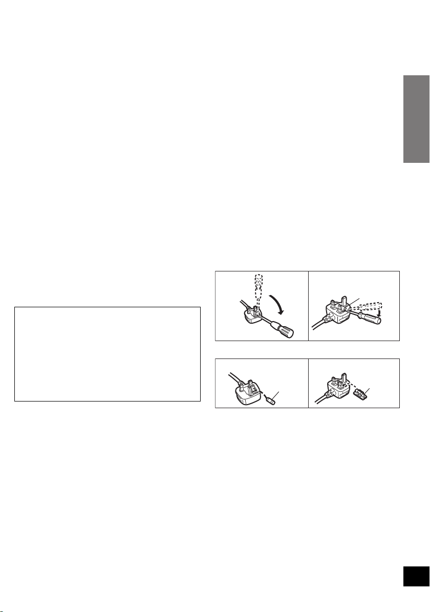
Caution for AC Mains Lead
Figure A Figure B
Fuse cover
Figure A Figure B
Fuse
(5 ampere)
Fuse
(5 ampere)
(For the United Kingdom and Ireland)
For your safety, please read the following text
carefully.
This appliance is supplied with a moulded three pin
mains plug for your safety and convenience.
A 5-ampere fuse is fitted in this plug.
Should the fuse need to be replaced please ensure
that the replacement fuse has a rating of 5-ampere
and that it is approved by ASTA or BSI to BS1362.
Check for the ASTA mark Ï or the BSI mark Ì on
the body of the fuse.
If the plug contains a removable fuse cover you
must ensure that it is refitted when the fuse is
replaced.
If you lose the fuse cover the plug must not be used
until a replacement cover is obtained.
A replacement fuse cover can be purchased from
your local dealer.
CAUTION!
IF THE FITTED MOULDED PLUG IS
UNSUITABLE FOR THE SOCKET OUTLET IN
YOUR HOME THEN THE FUSE SHOULD BE
REMOVED AND THE PLUG CUT OFF AND
DISPOSED OF SAFELY.
THERE IS A DANGER OF SEVERE
ELECTRICAL SHOCK IF THE CUT OFF PLUG
IS INSERTED INTO ANY 13-AMPERE SOCKET.
WARNING: DO NOT CONNECT EITHER WIRE
TO THE EARTH TERMINAL WHICH IS MARKED
WITH THE LETTER E, BY THE EARTH SYMBOL
Ó
OR COLOURED GREEN OR GREEN/
YELLOW.
THIS PLUG IS NOT WATERPROOF—KEEP
DRY.
Before use
Remove the connector cover.
How to replace the fuse
The location of the fuse differ according to the type
of AC mains plug (figures A and B). Confirm the AC
mains plug fitted and follow the instructions below.
Illustrations may differ from actual AC mains plug.
1. Open the fuse cover with a screwdriver.
2. Replace the fuse and close or attach the fuse cover.
If a new plug is to be fitted please observe the
wiring code as stated below.
If in any doubt please consult a qualified electrician.
IMPORTANT
The wires in this mains lead are coloured in
accordance with the following code:
Blue: Neutral, Brown: Live.
As these colours may not correspond with the
coloured markings identifying the terminals in your
plug, proceed as follows:
The wire which is coloured Blue must be connected
to the terminal which is marked with the letter N or
coloured Black or Blue.
The wire which is coloured Brown must be
connected to the terminal which is marked with the
letter L or coloured Brown or Red.
3
VQT3R83
Page 4

Table of Contents
Safety precautions .............................................................................................. 2
Caution for AC Mains Lead ................................................................................ 3
Before use
Accessories ......................................................................................................... 5
Unit care ............................................................................................................... 5
Control reference guide ...................................................................................... 6
Active subwoofer ..................................................................................................................... 6
Remote control ........................................................................................................................ 7
Getting started
Step 1 Selecting the placement method ........................................................... 8
Speaker system ...................................................................................................................... 9
Active subwoofer ..................................................................................................................... 9
Step 2 Assembling the speakers ..................................................................... 10
When placing the speakers on a wall ................................................................................... 10
When placing the speakers on a table .................................................................................. 13
Speaker fall prevention measures ........................................................................................ 16
Step 3 Connections ........................................................................................... 18
Basic connection ................................................................................................................... 18
Connection with HDMI compatible devices ........................................................................... 20
Speaker cable connection ..................................................................................................... 21
AC mains lead connection .................................................................................................... 21
Operations
Using this unit ................................................................................................... 22
3D sound .............................................................................................................................. 23
Audio output modes .............................................................................................................. 23
Linked operations with the TV (VIERA Link “HDAVI ControlTM”) ..................... 24
Advanced operations ........................................................................................ 25
Reference
Troubleshooting ................................................................................................ 26
Indicator illumination ........................................................................................ 28
Specifications .................................................................................................... 29
Licenses ............................................................................................................. 30
4
VQT3R83
Page 5
Precautions
Reference Getting started
Before useOperations
≥ The illustrations shown may differ from your unit.
For Thailand
For Saudi
Arabia and
Kuwait
≥ These operation instructions are applicable to model SC-HTB15 for variety of regions.
Unless otherwise indicated, illustrations in these Operating Instructions are of the model for
the United Kingdom and Ireland.
≥ Operations in these Operating Instructions are described mainly with the remote control, but
you can perform the operations on the active subwoofer if the controls are the same.
System SC-HTB15
Active subwoofer (main unit) SU-HTB15
Speaker system SB-HTB15
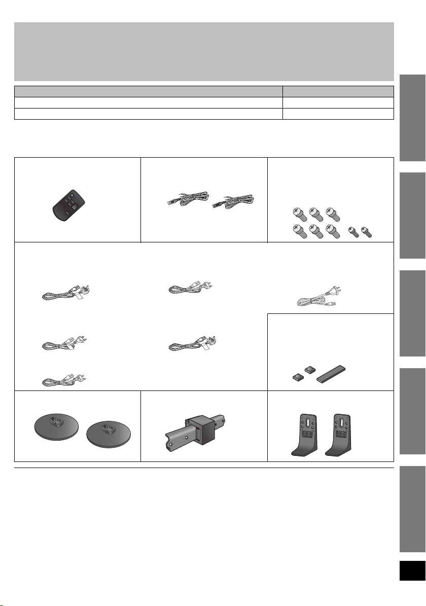
Accessories
Check the supplied accessories before using the system.
∏ 1 Remote control
(with a battery)
(N2QAYC000046)
∏ AC mains lead
1 For the United Kingdom
and Ireland
(K2CZ3YY00005)
∏ 2 Speaker cables
(REEX1266A: RED)
(REEX1267A: WHITE)
1 For Continental Europe
(K2CQ2CA00007)
∏ 8 Screws
[XYN5+J14FJK:
Screw A (Largek6)]
[XYN3+F10FJK:
Screw B (Smallk2)]
1 For Australia and
New Zealand
(K2CJ2DA00010)
3 For South East Asia and the Middle East
(K2CP2CA00001)
(K2CQ2CA00007)
∏ 2 Bases
(RYK1637A-K)
(K2CZ3YY00005)
∏ 1 Speaker joint
(RAQ0082)
∏ 3 Speaker feet
(RKA0072-KJ:
Speaker foot Ak2)
(RMG0859-K:
Speaker foot Bk1)
∏ 2Stands
(RYQ0853-K)
≥ Product numbers are correct as of June 2011. These may be subject to change.
Unit care
∫ Clean the system with a soft, dry cloth
≥
When dirt is heavy, wring a cloth moistened in water tightly to wipe the dirt, and then wipe it with a dry cloth.
≥ When cleaning the system, use a fine cloth. Do not use tissues or other materials (towels, etc.) that can
fall apart. Small grains may get stuck inside the speaker cover.
≥ Never use alcohol, paint thinner or benzine to clean the system.
≥ Before using chemically-treated cloth, carefully read the instructions that came with the cloth.
5
VQT3R83
Page 6
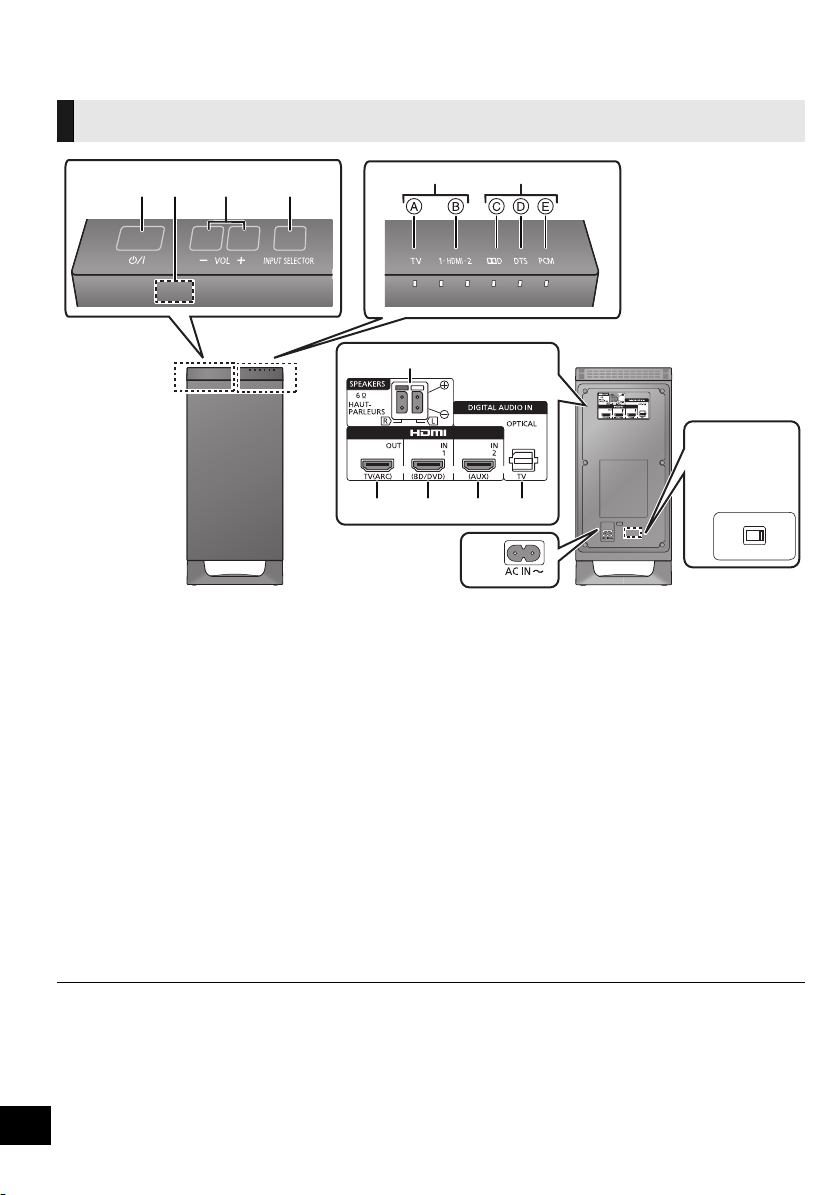
Control reference guide
VOLT ADJ
110-127V• •220-240V
314
56
2
7
8 9 10 11
12
(For South
East Asia and
the Middle
East)
13
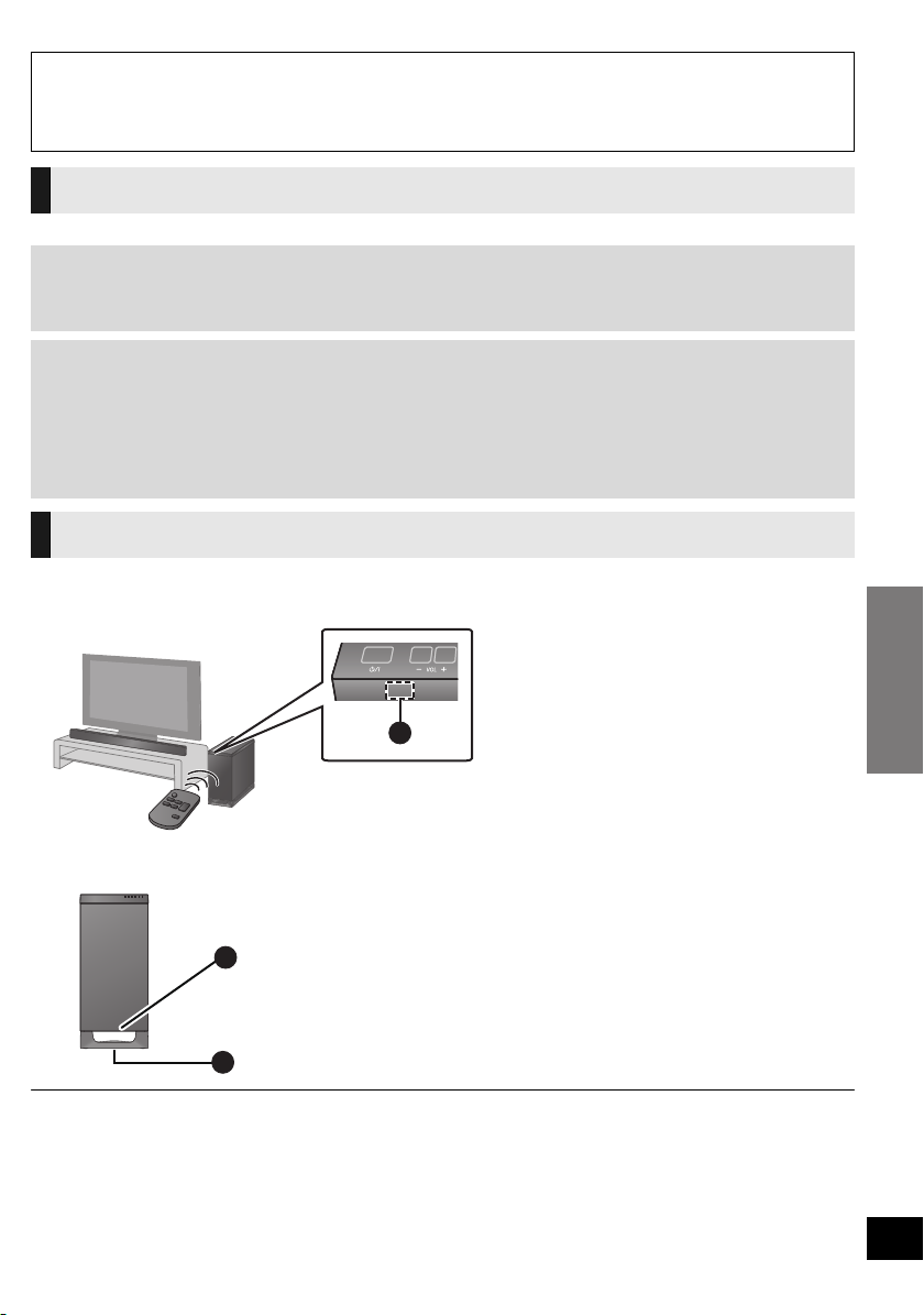
Active subwoofer
(front)
Active subwoofer
(rear)
Active subwoofer
1 Standby/on switch (Í/I)
Press to switch the unit from on to standby
mode or vice versa. In standby mode, the unit
is still consuming a small amount of power.
2 Remote control signal sensor (> 9)
3 Adjust the volume of the speakers
4 Select the input source
TV # HDMI 1 # HDMI 2
^----------------------------------}
5 Input selector indicators
A TV indicator
B HDMI IN 1, HDMI IN 2 indicator
§ The indicators will also blink in various conditions (> 28)
§
Lights green when the TV is the audio
source
When the device connected to the HDMI IN
1 terminal or the HDMI IN 2 terminal is the
audio source (B lights in amber)
6
VQT3R83
6 Audio format indicators
7 Speaker terminals (> 21)
8 HDMI OUT terminal (ARC compatible) (> 18)
9 HDMI IN 1 terminal (> 20)
10 HDMI IN 2 terminal (> 20)
11 OPTICAL DIGITAL AUDIO IN terminal (> 19)
12 AC IN terminal (> 21)
13 AC Voltage selector (> 21)
§
C Dolby Digital indicator
Lights when Dolby Digital is the current
audio format
D DTS indicator
Lights when DTS is the current audio
format
E PCM indicator
Lights when PCM (2ch, Multi-channel) is
the current audio format
Page 7
Before use
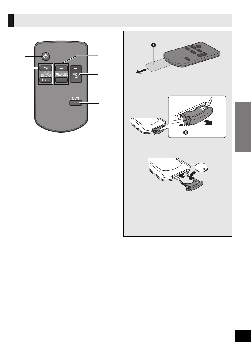
Remote control
1
2
3
4
5
1 Turn the system on or off (> 22)
2 Select the input source (> 22)
≥ [TV]:
Select the TV as the source
≥ [HDMI 1/2]:
Select the device connected to the HDMI IN 1
or HDMI IN 2 terminal as the source
3 Adjust the output level of the active subwoofer
(bass sound) (> 22)
4 Adjust the volume of the speakers (> 22)
5 Mute the sound (> 22)
Remove the insulation sheet A before using.
∫ To replace a button-type battery
1 While pressing the stopper B, pull out the
battery holder.
2 Set the button-type battery with its (i) mark
facing upward and then put the battery
holder back in place.
≥ When the button-type battery runs down,
replace it with a new battery (part number:
CR2025). The battery should normally last
about 1 year, however, this depends on how
frequently the unit is used.
≥ Keep the button-type battery out of reach of
children to prevent swallowing.
7
VQT3R83
Page 8
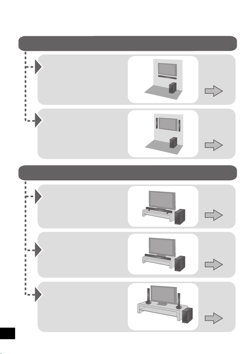
Step 1 Selecting the placement method
When placing the speakers on a wall
When placing the speakers on a table
Place the speakers
horizontally
Page 10
Place the speakers
vertically
Place the speakers using
the base stands
Place the speakers using
the stands
Place the speakers using
the speaker feet
Page 12
Page 13
Page 14
Page 15
≥ These are examples of placement methods.
8
VQT3R83
Page 9
Getting started
Caution
A
A Remote control signal sensor
≥ Remote control operation range
Distance: Within approx. 7 m directly
in front
Angle: Approx. 30
o
left and right
B
C
≥ The active subwoofer and supplied speakers are to be used only as indicated in these instructions. Failure to do so may lead to
damage to the amplifier and/or the speakers, and may result in the risk of fire. Consult a qualified service person if damage has
occurred or if you experience a sudden change in performance.
≥ Do not attempt to attach these speakers to a wall using methods other than those described in this manual.
Speaker system
≥ Do not hold the speakers in one hand to avoid injury by dropping the speakers when carrying.
∫ When placing the speakers on a wall
The wall or pillar on which the speakers are to be attached should be capable of supporting 33 kg per screw. Consultation with a
qualified building contractor is recommended when attaching the speakers to a wall. Improper attachment may result in damage to
the wall and speakers, and personal injury.
∫ When placing the speakers in front of the TV
The speakers may block or interfere with the TV’s various sensors (C.A.T.S. (Contrast Automatic Tracking System) sensor, remote
control sensor, etc.) and the 3D Eyewear transmitters on a 3D compatible TV.
≥ If the stands are being used
Move the speakers farther away from the TV. If the TV still does not function correctly, try removing the stands.
≥ If the stands are not used
Move the speakers farther away from the TV. If the TV still does not function correctly, try using them beside the TV (> 8).
Active subwoofer
The remote control signal sensor is located on the active subwoofer.
≥ Use the remote control within the correct operation range.
∫ When carrying the active subwoofer
B Do not hold the active subwoofer from this opening.
The parts inside (speaker unit) may be damaged.
C Always hold the bottom of the active subwoofer when
moving it.
≥ Place the active subwoofer in a horizontal position with the top panel faced upward.
≥ Placing the active subwoofer and the speakers too close to the walls, and corners can result in excessive bass. Cover walls and
windows with thick curtains.
≥ If irregular colouring occurs on your TV, turn the TV off for about 30 minutes. If it persists, move the speakers further away from
the TV.
≥ Keep magnetised items away. Magnetised cards, watches etc., can be damaged if placed too close to the system.
9
VQT3R83
Page 10
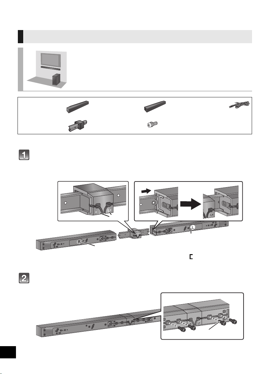
Step 2 Assembling the speakers
R
2
4
1
3
When placing the speakers on a wall
Place the speakers horizontally
∏ 1 Speaker (L) ∏ 1 Speaker (R) ∏ 2 Speaker cables
∏ 1 Speaker joint ∏ 4 Screws A
(Large)
≥ For a safety measure to prevent the speakers from falling, refer to page 16.
≥ To prevent damage or scratches, lay down a soft cloth and perform the assembly on it.
(L): WHITE
(R): RED
Match the L/R indicator A on the speaker with the L/R indicator B on the
speaker joint, then insert the metal part of the speaker joint fully into C.
≥ Do not connect the left speaker to the right speaker joint or vice versa. Be sure to verify the orientation of the speaker with
the label on the rear of the speaker.
“”
C
A L/R indicator on the
speaker label
B L/R indicator on the
speaker joint
shaped slit
Use screws A to secure the speakers to the speaker joint.
≥ Keep the screws out of reach of children to prevent swallowing.
10
VQT3R83
D Screw A (supplied)
≥ Be sure to insert the screws following the order as indicated in the illustration.
Page 11

Getting started
Connect the speaker cables.
Push
≥ To make sure that the speaker cable is connected to the correct speaker, match the colour of the speaker connector with the
colour of the L/R indicator on the speaker label so as not to connect the speaker cable to the wrong speaker.
≥ Insert the wire fully, taking care not to insert beyond the wire insulation.
1 Insert the wire fully.
r: White
s: Blue line
2 Press into the
groove.
Drive a screw (not supplied) into the wall.
≥ Use the measurements indicated below to identify the screwing positions on the wall.
≥ Leave at least 20 mm of space above and each side of the speaker to allow enough space for fitting the speaker.
≥ The position in the wall where the screw is to be attached as well as the screw should be capable of supporting over 33 kg.
≥ Keep the screws out of reach of children to prevent swallowing.
A At least 30 mm
B ‰4.0 mm
C ‰7.0 mm to ‰9.4 mm
D Wall or pillar
E 5.5 mm to 6.5 mm
F 211 mm G 388 mm H 201 mm I 14.3 mm
Fit the speaker securely onto the screw(s) with the hole(s).
DO DO NOT
≥ Move the speaker so
that the screw is in
this position.
≥ In this position, the
speaker will likely fall
if moved to the left or
right.
11
VQT3R83
Page 12

Place the speakers vertically
Push
∏ 1 Speaker (L) ∏ 1 Speaker (R) ∏ 2 Speaker cables
≥ For a safety measure to prevent the speakers from falling, refer to page 16.
≥ To prevent damage or scratches, lay down a soft cloth and perform the assembly on it.
(L): WHITE
(R): RED
Connect the speaker cables.
≥ Insert the wire fully, taking care not to insert beyond the wire insulation.
≥ To make sure that the speaker cable is connected to the correct speaker, match the colour of the speaker connector with the
colour of the L/R indicator on the speaker label so as not to connect the speaker cable to the wrong speaker.
1 Insert the wire fully.
r: White
s: Blue line
2 Press into the groove.
Drive a screw (not supplied) into the wall.
≥ Use the measurements indicated below to identify the screwing positions on the wall.
≥ Leave at least 20 mm of space above and each side of the speaker to allow enough space for fitting the speaker.
≥ The position in the wall where the screw is to be attached as well as the screw should be capable of supporting over 33 kg.
≥ Keep the screws out of reach of children to prevent swallowing.
A At least 30 mm
B ‰4.0 mm
C ‰7.0 mm to
‰9.4 mm
D Wall or pillar
E 5.5 mm to 6.5 mm
F 55 mm
G 24.5 mm
12
VQT3R83
Fit the speaker(s) securely onto the screw(s) with the hole(s).
DO DO NOT
≥ Move the speaker so
that the screw is in this
position.
≥ In this position, the
speaker will likely fall if
moved to the left or
right.
Page 13

Getting started
When placing the speakers on a table
Align the holes
with the projecting
parts on the
speaker.
Do not use these
holes for the
alignment. If these
are used, the
screw does not fit.
Place the speakers using the stands
∏ 1 Speaker (L) ∏ 1 Speaker (R) ∏ 2 Speaker cables
∏ 1 Speaker joint ∏ 2 Stands ∏ 6 Screws A
≥ For a safety measure to prevent the speakers from falling, refer to page 16.
≥ To prevent damage or scratches, lay down a soft cloth and perform the assembly on it.
(L): WHITE
(R): RED
(Large)
Assemble the speakers following steps 1 to 3 of “Place the speakers
horizontally” (> 10).
Attach the stands.
≥ Keep the screws out of reach of children to prevent swallowing.
A Screw A (supplied)
B Screw hole
13
VQT3R83
Page 14

Place the speakers using the speaker feet
B:
A:
∏ 1 Speaker (L) ∏ 1 Speaker (R) ∏ 2 Speaker cables
∏ 1 Speaker joint ∏ 4 Screws A
(Large)
≥ For a safety measure to prevent the speakers from falling, refer to page 16.
≥ To prevent damage or scratches, lay down a soft cloth and perform the assembly on it.
(L): WHITE
(R): RED
∏ 3 Speaker feet
Assemble the speakers following steps 1 to 3 of “Place the speakers
horizontally” (> 10).
Attach the speaker feet to the bottom of the speakers.
≥ Keep the speaker feet out of reach of children to prevent swallowing.
A Speaker foot A (supplied)
≥ Attach the speaker foot A directly below the centre of
the tweeter (as illustrated).
B Speaker foot B (supplied)
≥ Attach the speaker foot to the position indicated in the
illustration.
14
VQT3R83
Page 15

Getting started
Place the speakers using the base stands
Leave about 110 mm
Position the cable between the ridges.
Screw B (supplied)
≥ Tighten securely.
∏ 1 Speaker (L) ∏ 1 Speaker (R) ∏ 2 Speaker cables
∏ 2 Bases ∏ 2 Screws B
(Small)
≥ For a safety measure to prevent the speakers from falling, refer to page 16.
≥ To prevent damage or scratches, lay down a soft cloth and perform the assembly on it.
(L): WHITE
(R): RED
Insert the speaker cable through the base.
≥ Be sure to insert the speaker cable through the threading hole as indicated in the illustration.
A Threading hole B Screw hole
Attach the speaker to the base.
≥ To make sure that the speaker cable is connected to the correct speaker, match the colour of the speaker connector with the
colour of the L/R indicator on the speaker label so as not to connect the speaker cable to the wrong speaker.
≥ Keep the screws out of reach of children to prevent swallowing.
(Continued on the next page)
15
VQT3R83
Page 16

Connect the speaker cables.
Insert the
wire fully.
r: White
s: Blue line
Press into the groove.
Push
Back of the base
Pull the cable
straight along
the line and
slide into the
groove.
≥ Be sure to place
the cable under
the projecting
part.
Wall-mounted speakers (>11)
Wall-mounted speakers (>12)
≥ Insert the wire fully, taking care not to insert beyond the wire insulation.
Speaker fall prevention measures
To prevent the speakers from falling, it is recommended, as an additional
protection measure, to attach the speakers to the wall or table with a fall
prevention cord (hereafter “cord”).
≥ Consultation with a qualified housing contractor concerning the appropriate procedure when attaching to a concrete wall or a
surface that may not have strong enough support is recommended
wall and speakers, and personal injury.
≥ Use a cord of less then ‰2.0 mm, which is capable of supporting over 10 kg.
≥ Keep the screws out of reach of children to prevent swallowing.
≥ Make sure that the slack of the cord is minimal.
When placing the speakers on a wall
(>11
, 12)
. Improper attachment may result in damage to the
16
VQT3R83
Horizontal placement
Vertical placement
A Cord (not supplied)
B Screw eye (not supplied)
C Wall
D TV
Page 17

Getting started
When placing the speakers on a table
Horizontal placement
Vertical placement
A Cord (not supplied)
B Screw eye (not supplied)
≥ Depending on the placement of the speakers, the
screwing position of the screw eye may differ.
C Wall
D Approx. 150 mm
17
VQT3R83
Page 18

Step 3 Connections
HDMI (ARC)
TV
Active
subwoofer
Be sure to connect to the TV’s ARC
compatible terminal. (Refer to the
operating instructions for the TV.)
≥ Turn off all equipment before connection and read the appropriate operating instructions.
Do not connect the AC mains lead until all other connections are complete.
∫ HDMI
The HDMI connection supports VIERA Link “HDAVI Control” (> 24) when used with a compatible Panasonic TV.
≥ Use High Speed HDMI Cables that have the HDMI logo (as shown on the cover). It is recommended that you use Panasonic’s
HDMI cable.
Recommended part number (High Speed HDMI cable):
RP-CDHS15 (1.5 m), RP-CDHS30 (3.0 m), RP-CDHS50 (5.0 m), etc.
≥ Non-HDMI-compliant cables cannot be utilised.
∫ 3D compatibility
Compatible with FULL HD 3D TV and Blu-ray Disc Player
≥ This system can pass through the 3D video signal from a 3D compatible Blu-ray Disc Player to a FULL HD 3D TV.
Basic connection
Verify if the TV’s HDMI terminal is labelled “HDMI (ARC)”.
The connection will differ when the TV’s HDMI terminal is labelled “HDMI (ARC)” and when it is not.
Labelled “HDMI (ARC)”: Connection ]A[
Not labelled “HDMI (ARC)”: Connection ]B[ (> 19)
∫ What is ARC?
ARC is an abbreviation of Audio Return Channel, also known as HDMI ARC. It refers to one of the HDMI functions. When you
connect the active subwoofer to the terminal labelled “HDMI (ARC)”, the optical digital audio cable that is usually required in order
to listen to sound from a TV is no longer required, and TV pictures and sound can be enjoyed with a single HDMI cable.
Make the connection.
18
VQT3R83
[A] Labelled “HDMI (ARC)”
A HDMI cable (not supplied)
Page 19

Getting started
[B] Not labelled “HDMI (ARC)”
HDMI IN
OPTICAL OUT
TV
Active subwoofer
A HDMI cable (not supplied)
B Optical digital audio cable
(not supplied)
19
VQT3R83
Page 20

Connection with HDMI compatible devices
HDMI OUT
HDMI OUT
e.g., Video game console
e.g., Blu-ray Disc Player
Active subwoofer
You can output the audio signal from the connected HDMI compatible Blu-ray Disc player, DVD player, etc.
with this system and pass the signal through to your TV.
≥When connecting other external device such as a set top box, refer to the operating instructions for the
TV.
Preparation
≥ Connect this system to the TV. (> 18, 19)
A HDMI cable (not supplied)
∫ HDMI standby pass-through
Even if this system is in standby mode, the audio and/or video signal from the device connected to the HDMI IN 1 or HDMI IN 2
terminal will be sent to the TV connected to the HDMI OUT terminal (The sound will not be output from this system). When devices
are connected to both HDMI IN 1 and HDMI IN 2 terminals, audio and/or video signal of the device whose input is lastly selected is
output.
20
VQT3R83
Page 21

Getting started
Speaker cable connection
Active subwoofer
VOLT ADJ
110-127V• •220-240V
Active subwoofer
(For South East Asia and the Middle East)
Before connecting the AC mains lead
Set the voltage.
Use a flat-head screwdriver to move the voltage
selector to the appropriate position for the area in
which this system is used.
Connect to the terminals of the same colour.
AC mains lead connection
≥ Connect only after all other connections are complete.
A RED
Front speaker (Rch)
B WHITE
Front speaker (Lch)
A To a household mains socket
[For\South\East\Asia\and\the\Middle\East]
Use the AC mains lead that matches the socket for the area you live in.
[For\the\United\Kingdom,\Ireland,\Saudi\Arabia\and\Kuwait]
BE SURE TO READ THE CAUTION FOR THE AC MAINS LEAD ON PAGE 3 BEFORE
CONNECTION.
≥ The active subwoofer consumes a small amount of AC power, even when it is in standby mode (0.1 W).
In the interest of power conservation, if you will not be using this system for a long time, unplug it from
the household mains socket.
≥ The supplied AC mains lead is for use with the active subwoofer.
Do not use it with other equipment. Also, do not use cords for other equipment with the active subwoofer.
21
VQT3R83
Page 22

Using this unit
Preparation
≥ Turn on the TV.
Press [Í] to turn on the system.
Press [TV] or [HDMI 1/2] to select
the input source. (> 6)
≥ If you have selected [HDMI 1/2], make sure to select the
TV’s input mode for this system and start the playback.
Press [i VOL j] to adjust the
volume of the speakers.
≥ Volume range: 1 to 100
§
Press [i SUBWOOFER j] to
adjust the subwoofer level
(bass sound).
≥ Subwoofer levels: 1 to 4
§ The audio format indicators blink from left to
right (i) or from right to left (s) while adjusting
the speaker volume or the subwoofer level.
The indicators will not blink when it has reached
the maximum or minimum.
§
If the system does not operate as expected
such as sound defects, return the settings to
the factory preset and operate the system
again. (> 26)
∫ To mute the sound
Press [MUTE].
The audio format indicators
blink simultaneously while
muting.
≥ To cancel, press the button again or adjust the
volume.
≥ Muting is cancelled if this system is turned off.
22
VQT3R83
Audio format indicator
≥ If there is sound coming out of the TV’s speakers, reduce the
volume of the TV to its minimum.
≥ The maximum volume of the TV and this system may be
different.
≥ If this system is turned off with the volume setting in the
greater half (above 50), this system will automatically lower
the volume to the middle (50) when the system is turned on.
(Refer to page 25 to turn this function off.)
≥ The volume may be displayed on the TV if the active
subwoofer is connected to a Panasonic TV capable of
displaying this system’s volume setting.
Page 23

Operations
3D sound
e.g., Image of 3D sound field
This system provides a feeling that the sound and
the image are as one. The 3D sound effect will be
applied to Multi-channel audio sources as a factory
preset.
3D sound
Dolby Virtual
Speaker
3D surround
effect
Clear-mode
dialog
With this effect you can enjoy a
surround sound effect similar to
5.1ch.
Adding to the Dolby Virtual
Speaker effect, Panasonic has
applied its own sound field
controlling technology to expand
the sound field forwards,
backwards, upwards and
downwards providing a sound with
depth and force that better
matches 3D images.
Sports commentary and dialogs
from TV dramas are heard as if
the sound is coming from the TV,
giving the feeling that the sound
and the image is as one.
Also, the dialog will stand out from
the other sounds during normal
volume playback and when the
volume is lowered for night time
viewing.
Audio output modes
As a factory preset, Dolby Virtual Speaker and the
3D surround effects will be applied to Multi-channel
audio sources, such as those from a Blu-ray Disc
player or DVD player, etc.
By changing the audio output setting, it is possible
to apply the Dolby Virtual Speaker and 3D surround
effects to 2ch audio sources, such as the audio
from the TV.
Dolby Virtual Speaker
Audio output mode
Multi-channel mode
Auto mode (Direct mode)
(Factory preset)
2
2ch mode
§1 Depending on the audio source, Dolby Virtual Speaker and
3D surround effect settings are automatically adjusted.
§2 This indicator will also light when the audio source is Multichannel audio.
To change the audio
output mode
and 3D surround
The effects are
applied to all audio
sources.
§1
The effects are
applied to Multichannel audio
sources.
The effects are not
applied to 2 channel
audio sources.
The effects are not
applied to any audio
source.
effect
Dolby Virtual Speaker and the 3D surround effects can be
turned off and on by changing the audio output mode settings.
Press and hold [MUTE] for more
than 2 sec.
≥ The indicator for the current setting blinks for 10 sec.
While the indicator is blinking,
press [MUTE] again to change
the setting.
≥ The setting changes each time [MUTE] is pressed.
When using the optical digital audio cable, Dolby Virtual
Speaker and the 3D surround effect will be automatically
cancelled if the audio signal’s sampling frequency is greater
than 48 kHz.
23
VQT3R83
Page 24

Linked operations with the TV
(VIERA Link “HDAVI ControlTM”)
What is VIERA Link “HDAVI
Control”?
VIERA Link “HDAVI Control” is a convenient
function that offers linked operations of this
system, and a Panasonic TV (VIERA) under
“HDAVI Control”.
You can use this function by connecting the
equipment with an HDMI cable. See the
operating instructions for connected
equipment for operational details.
Preparation
1 Confirm that the HDMI connection has been
made. (> 18 to 20)
2 Set the “HDAVI Control” operations on the
connected equipment (e.g., TV).
3 For the optimal “HDAVI Control” operations
change the following settings on the connected
§
1
.
TV
≥ Set the default speaker settings to this
system.
§
2
≥ Set the speaker selection settings to this
system.
4 Turn on all “HDAVI Control” compatible
equipment and select the TV’s input for this
system so that the “HDAVI Control” function
works properly.
5 If a device is connected to the HDMI IN
terminal, start play to check that the picture is
displayed on the TV correctly.
When the connection or settings are changed,
repeat this procedure.
§1 The availability and function of the settings may vary
depending on the TV. Refer to the operating instructions for
the TV for details.
§2 If the TV has a default speaker setting within the VIERA
Link setting items, choosing this system as the default
speaker will automatically change the speaker selection to
this system.
≥ VIERA Link “HDAVI Control”, based on the control functions
provided by HDMI which is an industry standard known as
HDMI CEC (Consumer Electronics Control), is a unique
function that we have developed and added. As such, its
operation with other manufacturers’ equipment that supports
HDMI CEC cannot be guaranteed.
≥ This unit supports “HDAVI Control 5” function.
“HDAVI Control 5” is the newest standard (current as of
December, 2010) for Panasonic’s HDAVI Control compatible
equipment. This standard is compatible with Panasonic’s
conventional HDAVI equipment.
≥ Please refer to individual manuals for other manufacturers’
equipment supporting VIERA Link function.
24
VQT3R83
What you can do with
VIERA Link “HDAVI Control”
To make sure that the audio is output from this
system, select home cinema speaker from the
speaker menu of VIERA Link menu using the TV’s
remote control to turn this system on. The
availability and function of the settings may vary
depending on the TV. Refer to the operating
instructions for the TV for details.
∫ Speaker control
You can select whether audio output is from this
system or the TV speakers by using the TV menu
settings.
Home cinema
This system is active.
≥ When this system is in standby mode, changing the TV
speakers to this system in the VIERA Link menu will
automatically turn this system on and select TV as the
source.
≥ You can control the volume setting of this system using the
volume or mute button on the TV remote control.
≥ If you turn off this system, TV speakers will be automatically
activated.
≥ Audio will automatically be output from this system if the TV
is compatible to VIERA Link “HDAVI Control 4” or later.
TV
TV speakers are active.
≥ The volume of this system is set to its minimum.
∫ Automatic input switching
When the following operations are performed, this
system will automatically change the input to the
corresponding source.
jWhen play starts on an HDMI connected
jWhen the TV input or the TV channel is changed.
§3 If the speaker output setting on the TV is set to this system,
∫ Power off link
When the TV is turned off, this system also turns off
automatically.
∫ Automatic lip-sync function
Delay between audio and video is automatically
adjusted by adding time-lag to the audio output,
enabling you to enjoy smooth audio for the picture.
The delay information is automatically set if the TV is
compatible to VIERA Link “HDAVI Control 3” or later and the
VIERA Link is set to on.
When the delay information cannot be retrieved, the audio
delay is set to 40 ms.
§3
device.
the TV and this system turn on automatically (Power on
link).
(for HDAVI Control 3 or later)
Page 25

Operations
Advanced
operations
The following settings are unnecessary under
general usage conditions of the system.
∫ Changing the dual audio
Change the dual audio from main to secondary.
1
Confirm the digital audio output setting on the
connected TV or player, etc. is set to “Bitstream”.
2 Press and hold [HDMI 1/2] for more than 2 sec.
While the indicator of the current setting is
3
flashing, press [HDMI 1/2] to change the setting.
A : Main
∫ To turn off the 3D surround effect and
clear-mode dialog effect
Depending on your preference, it is possible to use
only the Dolby Virtual Speaker effect by turning off
the 3D surround effect and the clear-mode dialog
effect.
1 Press and hold [TV] for more than 2 sec.
≥ The indicator for the current setting blinks for 10 sec.
Only Dolby Virtual Speaker is on.
3D surround effect and clear-mode
dialog effect are also on.
B : Secondary
A, B : Main and secondary
≥ The setting works only when the dual audio is
available in the audio source.
≥
The setting is maintained until it is changed again.
≥ The same setting is used for [TV] and [HDMI 1/2]
audio sources.
∫ Remote control code
When other Panasonic devices respond to this
system’s remote control, change the remote control
code on the active subwoofer and the remote control.
Preparation
≥ Turn off all other Panasonic products.
≥ Turn on this system.
Change the remote control code to code 2:
1 Aim the remote control at this system’s remote
control sensor.
2 Press and hold [MUTE] and [HDMI 1/2] on the
remote control for more than 4 sec.
≥ All the indicators will blink for 10 sec when the
code of this system is changed.
≥
The setting is maintained until it is changed again.
≥ If this system does not operate after changing the code,
repeat steps 1 and 2.
≥ To change the remote control code to code 1, repeat the
steps above, but replace [HDMI 1/2] with [TV].
2 While the indicator is blinking press [TV] to
change the setting.
≥ The setting changes each time [TV] is pressed.
≥ The setting will be reset to on when this system is turned off.
∫
To turn off VIERA Link “HDAVI Control”
When “HDAVI Control” compatible equipment does
not work well with this system, for example, it is
possible to turn off this function as follows:
≥ When VIERA Link is turned off the ARC function
is not available. Be sure to connect the optical
digital audio cable. (> 19)
1 Press and hold [MUTE] on the remote control
and [s VOL] on the active subwoofer for more
than 2 sec.
After the setting has changed, turn off all the
2
connected devices and then turn them on again.
∫ To reduce the clear-mode dialog effect
When the dialog does not sound natural while the
volume is set low, for example, it is possible to
reduce the dialog enhancing effect as follows:
Press and hold [TV] on the remote control and
[s VOL] on the active subwoofer for more than
2 sec.
∫ To turn off the volume limitation
If a state of the lowered volume disturbs you every
time this system turns on, for example, it is possible
to turn off this function as follows:
Press and hold [MUTE] on the remote control and
[VOL r] on the active subwoofer for more than
2 sec.
The settings of VIERA Link “HDAVI Control”, the clear-mode dialog
effect and the volume limitation remain intact even if you switch this
system to standby mode. To turn these 3 functions back on, this
system must be set back to the factory preset. (
≥ All the indicators will blink once when the setting is changed.
>
26)
25
VQT3R83
Page 26

Troubleshooting
Before requesting service, make the following
checks. If you are in doubt about some of the check
points, or if the solutions indicated in the following
guide do not solve the problem, consult your dealer
for instructions.
To return to the factory preset.
While this system is on, press [Í/I] on the active
subwoofer for more than 4 sec.
(All the indicators will blink twice when the active
subwoofer is reset.)
If the system does not operate as expected,
returning the settings to the factory preset
may solve the problem.
≥ The remote control code will return to “1” when
this system is returned to the factory preset. To
change the remote control code, refer to page
25.
General operation
No power.
≥ Insert the AC mains lead securely. (> 21)
≥ After turning this system on, if the indicators blink
and this system immediately turns off, unplug the
AC mains lead and consult your dealer.
The remote control does not work properly.
≥ The battery is depleted. Replace it with a new
one. (> 7)
≥ It is possible that the insulation sheet has not
been removed. Remove the insulation sheet.
(> 7)
≥ It may be necessary to set the code of the remote
control again after changing the battery of the
remote control. (> 25)
≥ Use the remote control within the correct
operation range. (> 9)
The “TV” indicator blinks, but there is no
sound.
Remove the AC mains lead and consult your
dealer. If there are any other indicators blinking, be
sure to inform the blinking indicators to your dealer.
HDMI
This system does not operate correctly.
If the HDMI cable is connected to the wrong
terminal (HDMI IN or HDMI OUT), this system will
not operate correctly. Turn this system off,
disconnect the AC mains lead and reconnect the
HDMI cable(s). (> 18 to 20)
VIERA Link related operations no longer
function properly.
≥ Check the VIERA Link setting on the connected
devices.
≥ Have you turned the VIERA Link settings off?
(> 25)
≥ When the HDMI connections are changed, after a
power failure or after the AC mains lead has been
removed, VIERA Link operations may not
function properly.
jTurn on all the devices that are connected to
the TV with an HDMI cable and then turn the
TV on.
jTurn off the VIERA Link settings of the TV and
turn it on again. For details refer to the
operating instructions for the TV.
jWhile this system and the TV are connected
with the HDMI cable, turn on the TV and then
remove the system’s AC mains lead and
reconnect it again.
The first few seconds of audio cannot be heard
when using the HDMI connection.
This may occur during DVD-Video chapter
playback. Change the digital audio output setting
on the connected device from “Bitstream” to “PCM”.
When operating an HDMI compatible device of a
different brand, this system reacts in an
unwanted manner.
HDAVI Control commands may use a different
signal depending on the brand of the device. In this
case, turn VIERA Link off (> 25).
This system is turned off when the TV’s
speakers are selected in the speaker control.
This is a normal feature when using VIERA Link
(HDAVI Control 4 or later). For details please read
the operating instructions for the TV on its power
save feature. (> 24)
26
VQT3R83
Page 27

Reference
Sound
No sound (or image).
≥ Turn muting off. (> 22)
≥ Check the connections to the other devices.
(> 18 to 20)
≥ Make sure that the received audio signal is
compatible with this system. (> 6)
≥ Turn this system off and then on again.
≥ If this system is connected to the TV with only an
HDMI cable, make sure that the TV’s HDMI
terminal is labelled “HDMI (ARC)”. If not, connect
using the optical digital audio cable. (> 18, 19)
≥ If this system is connected to a Panasonic TV
and turned on using the button on the active
subwoofer or the remote control, sound might not
be output from this system. In this case, turn this
system on using the TV’s remote control. (> 24)
≥ If the connections are correct, there might be a
problem with the cables. Redo the connections
with different cables.
≥ Check the audio output settings on the connected
device.
≥ If the HDMI 2 indicator flashes and there is no
audio output, try the following.
1 Turn the connected device off and then on.
2 Turn off this system, remove the HDMI cable,
then reconnect the HDMI cable and turn this
system back on.
The dual audio cannot be changed from main to
secondary.
If the audio received from the connected device is
not “Dolby Dual Mono” or the output setting is not
“Bitstream”, the setting cannot be changed from
this system. Change the setting on the connected
device.
The volume is lowered when this system is
turned on.
If this system is turned off with the volume setting in
the greater half (above 50), this system will
automatically lower the volume to the middle (50)
when this system is turned on. (> 25)
The dialog is too persistent or the dialog does
not sound natural.
This system has a function to make the dialog
stand out when the volume is low. (> 25)
There is no audio.
This system turns off automatically.
(When this system detects a problem, a safety
measure is activated and this system automatically
switches to standby mode.)
≥ There is a problem with the amplifier.
≥ Is the volume extremely high?
If so, lower the volume.
≥ Is this system placed in an extremely hot place?
If so, move this system to a cooler place and wait
a few moments and then try to turn it on again.
If the problem persists, confirm the TV indicator and
HDMI 2 indicator blink, turn the system off, remove
the AC mains lead and consult your dealer. Please
be sure to remember the indicators that were
blinking and inform the dealer.
27
VQT3R83
Page 28

Indicator illumination
The indicators display the condition of this system by flashing. The indicator patterns illustrated below are
displayed during normal operational conditions. They do not refer to the indications of a problem. Refer to
“Troubleshooting” (> 26) if the indicators do not light as illustrated below.
Indicator Description
The indicators blink from left to right (i) or from right to left (s).
≥ When the speaker volume or the subwoofer level is adjusted (> 22)
The indicators blink simultaneously.
≥ When “MUTE” is on (> 22)
The indicator blinks for 10 sec.
≥ When the audio output mode is Multi-channel mode (> 23)
≥ When 3D surround effect and clear-mode dialog effect are on (> 25)
≥ When the dual audio setting is Main (> 25)
The indicators blink for 10 sec.
≥ When the audio output mode is Auto mode (> 23)
The indicator blinks for 10 sec.
When the audio output mode is 2ch mode
≥
≥ When Dolby Virtual Speaker is on (> 25)
≥ When the dual audio setting is Secondary (> 25)
The indicators blink for 10 sec.
≥ When the dual audio setting is Main and Secondary (> 25)
(> 23)
28
VQT3R83
The indicators blink for 10 sec.
≥ When the remote control code is changed (> 25)
The indicators blink once.
≥ When changing the setting (To turn off VIERA Link “HDAVI Control”,
To reduce the clear-mode dialog effect and To turn off the volume
limitation) (> 25)
Page 29

Reference
Specifications
AMPLIFIER SECTION
RMS output power
10 % total harmonic distortion
Subwoofer ch
Front ch (L, R ch)
Total RMS Dolby Digital mode power 240 W
120 W per channel (100 Hz, 3≠)
60 W per channel (1 kHz, 6 ≠)
TERMINAL SECTION
HDMI
This unit supports “HDAVI Control 5” function.
HDMI AV input (HDMI 1, HDMI 2) 2
Input connector Type A (19 pin)
HDMI AV output (To TV (ARC)) 1
Output connector Type A (19 pin)
Digital audio input
Optical (TV) 1
Sampling frequency
88.2 kHz, 96 kHz (only Optical (TV) input, LPCM)
Audio format LPCM, Dolby Digital, DTS
Speaker output
(Front L, R) 2
32 kHz, 44.1 kHz, 48 kHz
SUBWOOFER SECTION
1 way, 1 speaker system (Bass reflex type)
Woofer 16 cm cone typek1
FRONT SPEAKER
SECTION
2 way, 2 speaker system (Bass reflex type)
Woofer 3.5 cmk10 cm cone typek1
Tweeter 2.5 cm semi dome typek1
SPEAKER GENERAL
Horizontal Placement using the Stands
Dimensions (WkHkD)
800 mmk89 mmk75 mm
Mass 1.4 kg
Horizontal Placement using the Speaker Feet
Dimensions (WkHkD)
800 mmk51 mmk58 mm
Mass 1.36 kg
Horizontal Placement (for wall mount)
Dimensions (WkHkD)
800 mmkApprox. 49 mmk58 mm
Mass 1.36 kg
Vertical Placement using the Base Stands
Dimensions (WkHkD)
135 mmk398 mmk135 mm
Mass 0.64 kg
Vertical Placement (for wall mount)
Dimensions (WkHkD)
Approx. 49 mmk380 mmk58 mm
Mass 0.59 kg
MAIN UNIT GENERAL
Power consumption 52 W
In standby condition 0.1 W
Power supply
For EG/EB/GN AC 220 V to 240 V, 50 Hz
For GS AC 110 V to 127 V/220 V to 240 V, 50/60 Hz
Dimensions (WkHkD)
180 mmk408 mmk305 mm
Mass 5.6 kg
Operating temperature range
Operating humidity range
20 % to 80 % RH (no condensation)
o
C to 40oC
0
1 Specifications are subject to change without notice.
2 Weight and dimensions are approximate.
3 Total harmonic distortion is measured by a digital spectrum
analyzer.
4 Total harmonic distortion is measured by using AES17 filter.
Model number suffix and destination
EB The United Kingdom and Ireland
EG Continental Europe
GN Australia and New Zealand
GS South East Asia and the Middle East
29
VQT3R83
Page 30

Information for Users on Collection and Disposal of Old Equipment and used Batteries
Cd
These symbols on the products, packaging, and/or accompanying documents mean
that used electrical and electronic products and batteries should not be mixed with
general household waste.
For proper treatment, recovery and recycling of old products and used batteries, please
take them to applicable collection points, in accordance with your national legislation
and the Directives 2002/96/EC and 2006/66/EC.
By disposing of these products and batteries correctly, you will help to save valuable
resources and prevent any potential negative effects on human health and the
environment which could otherwise arise from inappropriate waste handling.
For more information about collection and recycling of old products and batteries,
please contact your local municipality, your waste disposal service or the point of sale
where you purchased the items.
Penalties may be applicable for incorrect disposal of this waste, in accordance with
national legislation.
For business users in the European Union
If you wish to discard electrical and electronic equipment, please contact your dealer or
supplier for further information.
[Information on Disposal in other Countries outside the European Union]
These symbols are only valid in the European Union. If you wish to discard these items,
please contact your local authorities or dealer and ask for the correct method of
disposal.
Note for the battery symbol (bottom two symbol examples):
This symbol might be used in combination with a chemical symbol. In this case it
complies with the requirement set by the Directive for the chemical involved.
Licenses
Manufactured under license from Dolby
Laboratories. Dolby, Pro Logic, and the double-D
symbol are trademarks of Dolby Laboratories.
Manufactured under license under U.S. Patent
Nos: 5,956,674; 5,974,380; 6,487,535 & other
U.S. and worldwide patents issued & pending.
DTS, the Symbol, & DTS and the Symbol
together are registered trademarks & DTS Digital
Surround and the DTS logos are trademarks of
DTS, Inc. Product includes software.
© DTS, Inc. All Rights Reserved.
HDMI, the HDMI Logo, and High-Definition
Multimedia Interface are trademarks or
registered trademarks of HDMI Licensing LLC in
the United States and other countries.
HDAVI Control™ is a trademark of Panasonic
Corporation.
30
VQT3R83
Page 31

Reference
Safety information for customers in Finland and Norway
NORSK
ADVARSEL
Produkt
≥ For å redusere faren for brann, elektrisk støt eller
skade på apparatet:
jUtsett ikke produktet for regn, fukt, drypping
eller sprut.
jIkke plasser objekter som er fylt med væske,
som vaser, på apparatet.
jBruk kun anbefalt tilbehør.
jFjern ikke deksler.
jReparer ikke denne enheten selv, overlat
service til kvalifisert servicepersonell.
Vekselstrømnett
≥ Strømuttaket må befinne seg i nærheten slik at
den lett kan kobles fra uttaketumiddelbart om det
oppstår problemer.
FORSIKTIG
Produkt
≥ Plasser ikke åpen ild, slik som levende lys, oppå
apparatet.
≥ Dette apparatet er beregnet for bruk under
moderate klimaforhold.
Plassering
≥ For å redusere faren for brann, elektrisk støt eller
skade på apparatet:
jIkke plasser apparatet i en bokhylle, et
innebygget kabinett eller et annet lukket sted.
Pass på at produktet er godt ventilert.
jApparatets ventilasjonsåpninger må ikke
dekkes til med aviser, duker, gardiner eller
lignende.
SUOMI
VAROITUS
Laite
≥ Tulipalo-, sähköisku- tai vahinkovaaran
välttämiseksi,
jÄlä anna tämän laitteen altistua sateelle,
kosteudelle, pisaroille tai roiskeille.
jÄlä laita laitteen päälle mitään nesteitä
sisältäviä esineitä kuten maljakot.
jKäytä ainoastaan suositeltuja varusteita.
jÄlä poista suojuksia.
jÄlä korjaa tätä laitetta itse. Anna huoltopalvelut
tehtäväksi pätevälle henkilöstölle.
Verkkokaapeli
≥ Asenna tämä laite siten, että verkkokaapeli
voidaan irrottaa pistorasiasta välittömästi, jos
ilmenee ongelmia.
VAARA
Laite
≥ Älä laita avotulisia esineitä kuten kynttilöitä
laitteen päälle.
≥ Laite on tarkoitettu käytettäväksi leudoissa
ilmastoissa.
Sijoitus
≥ Tulipalo-, sähköisku- tai vahinkovaaran
välttämiseksi,
jÄlä asenna tai sijoita tätä laitetta kirjahyllyyn,
suljettuun kaappiin tai muuhun rajalliseen
tilaan. Varmista laitteen riittävä tuuletus.
jÄlä tuki laitteen tuuletusaukkoja lehdillä,
pöytäliinalla, verhoilla tai vastaavilla esineillä.
31
VQT3R83
Page 32

p
EU
\For\the\United\Kingdom\and\Ireland\customers\
Sales and Support Information
Customer Care Centre
≥ For customers within the UK: 0844 844 3852
≥ For customers within Ireland: 01 289 8333
≥ Visit our website for product information
www.panasonic.co.uk
≥ E-mail: customer.care@panasonic.co.uk
Direct Sales at Panasonic UK
≥ For customers: 0844 844 3856
≥ Order accessory and consumable items for your product with ease and confidence by phoning our
Customer Care Centre Monday–Thursday 9:00 a.m.–5:30 p.m., Friday 9:30 a.m.–5:30 p.m. (Excluding
public holidays)
≥ Or go on line through our Internet Accessory ordering application at www.pas-europe.com
≥ Most major credit and debit cards accepted.
≥ All enquiries transactions and distribution facilities are provided directly by Panasonic UK.
≥ It couldn’t be simpler!
≥ Also available through our Internet is direct shopping for a wide range of finished products, take a browse
on our website for further details.
.
EU
Pursuant to at the directive 2004/108/EC, article 9(2)
Panasonic Testing Centre
Panasonic Marketing Europe GmbH
Winsbergring 15, 22525 Hamburg, Germany
Panasonic Corporation
Web Site: http://panasonic.net
C Panasonic Corporation 2011 VQT3R83
F0611KA0
 Loading...