

Page 1
Panasonic
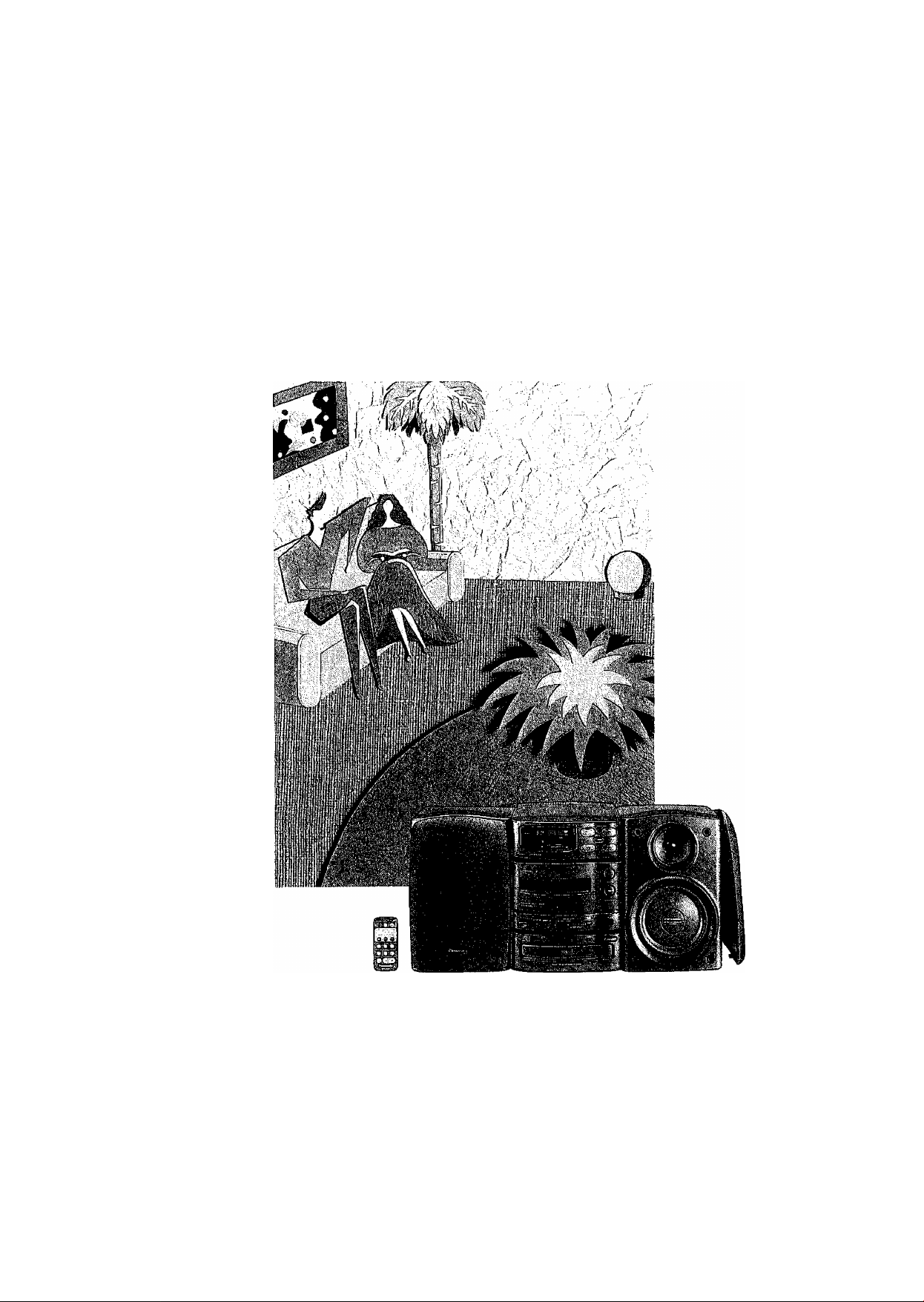
CD Stereo System
SC-CH150
Operating Instructions
Note:
The "EB” indication shown on the outside packing case indicates United Kingdom.
Before connecting, operating or adjusting this product, please read
these instructions completely.
flBl ISNl
n COMPACT
SJD§(§
DIGITAL AUDIO
RQT2133-B
Page 2

BMr
Thank you for purchasing this product.
For optimum performance and safety, please read these instructions
carefully.
(Back of product)
DANGER-tnvisible
laser radiation when
open,
AVOID DIRECT EX‘
POSURE TO BEAM.
(Inside of product)
CAUTION!
THIS PRODUCT UTILIZES A LASER.
USE OF CONTROLS OR ADJUSTMENTS OR PERFOR
MANCE OF PROCEDURES OTHER THAN THOSE SPECI
FIED HEREIN MAY RESULT IN HAZARDOUS RADIATION
EXPOSURE.
DO NOT OPEN COVERS AND DO NOT REPAIR YOUR
SELF. REFER SERVICING TO QUALIFIED PERSONNEL.
This unit employs a lithium battery for back-up of the memory if a
power failure occurs, but this battery will no longer provide that
back-up if it becomes weak. If battery replacement is necessary,
consult with the store where the unit was purchased, or any store
where Technics or Panasonic products are sold, or an authorized
Service Center. This battery must only be replaced by suitable
qualified service personnel.
WARNING
LITHIUM BATTERIES, POSSIBLE EXPLOSION DANGER,
CHANGE OF BATTERIES MUST ONLY BE DONE BY
QUALIFIED PERSONNEL.
THIS MUSIC SYSTEM IS CAPABLE OF RECEIVING THE NEW AM STEREO BROADCASTS FROM THE AM BAND
RADIO STATIONS. HOWEVER LIKE MANY MUSIC SYSTEM CURRENTLY AVAILABLE ON THE MARKET IT WILL
REPRODUCE THIS AM STEREO SIGNAL ONLY IN AM MONO, WHICH, IN EFFECT, IS OF NO LESSER QUALITY
THAN YOUR EXISTING AM MONO MUSIC SYSTEM.
Page 3
Wpiii
Si|s»i
'. '";!i:."^
Before use
Supplied Accessories .........................................
Caution for AC Mains Lead ................................. 4
Suggestions for Safety.......................................... 5
Concerning the Remote Control
Front Panel Controls
Connections
Setting the Time of Day
Memory Presetting
...........................................................
............................................
........................................
................................................
...........................
3
7
10
11
Operation
6
8
'.;, : ■■ ■. i ; ■ n ' V ' .■; r. \ " 'l.f,'.'
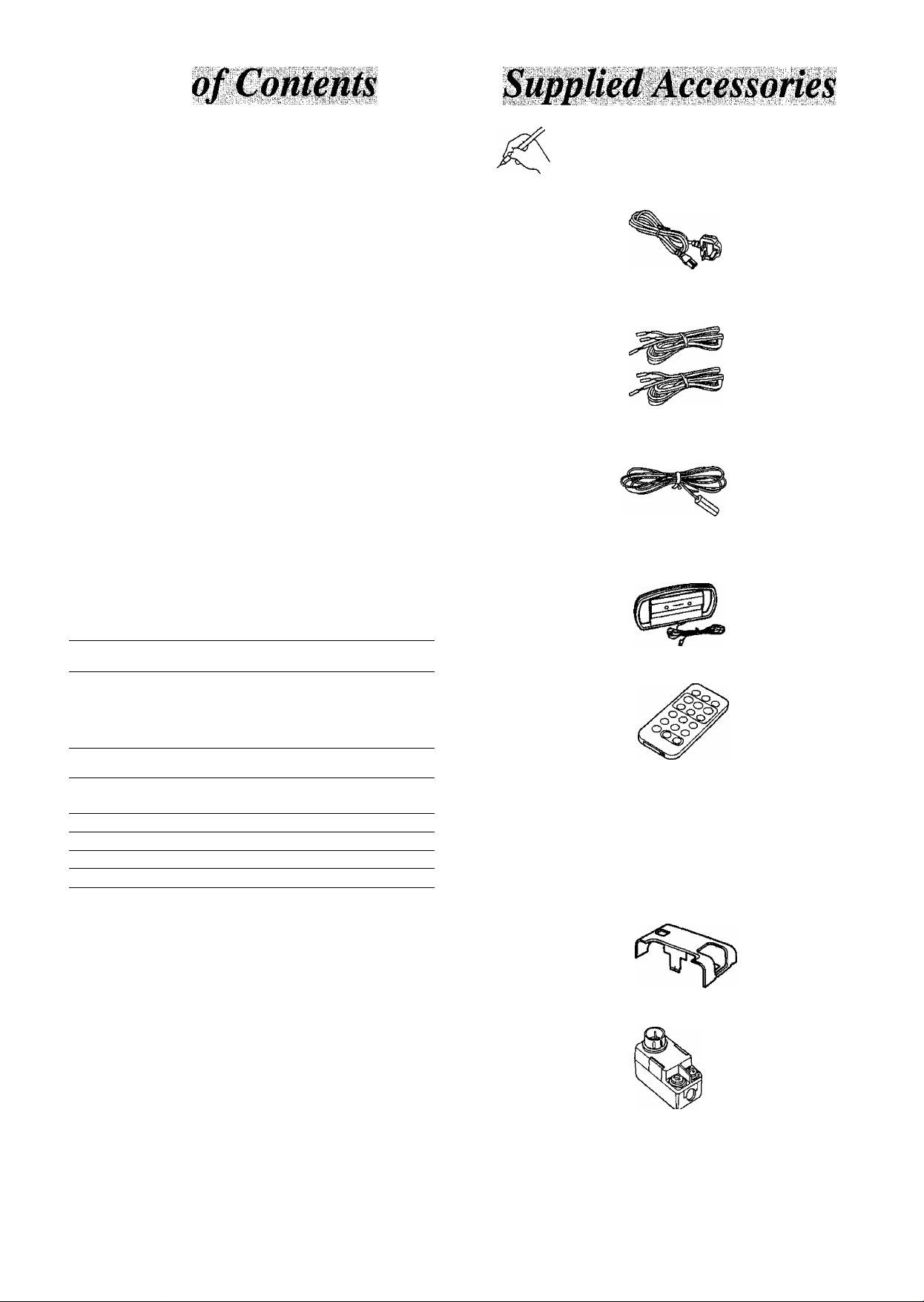
Please check and identify the supplied acces
sories.
0
□ AC power supply cord
(For United Kingdom: VJA0733or RJA0042-P)
(For Others: RJA0036-K}
......................................
1 pc,
Listening to Radio Broadcasts ...........................
Listening to Compact Discs
Listening to Tapes
One-Touch Playback
Handy Functions....................................................22
................................................
............................................
................................
14
16
20
22
Recording
Before Making a Recording
Recording Compact Discs
Recording Radio Broadcasts
..................................
....................................
.............................
23
24
30
Tone quality/soundfield
Changing the Tone Quality and
Sound Field
..........................................
............
32
Timer
Before Using the Timers
Using the Play-Timer ...............................
Using the Record Timer
Using the Sleep Timer .............................
Using the Timer in Combination ......
..........................
..........................
............
............
............
............
............
33
34
36
38
39
Q Speaker cable
(REE0499)
□ FM indoor antenna
(For United Kingdom: RSA0007)
(For Others: RSA0006)
D AM loop antenna
(RSA0009)
□ Remote control transmitter
(RAK-CH910WK)
□ Lithium battery
(CR2025/1 POD)
...................
2 pcs.
1 pc.
1 pc.
1 pc.
1pc.
Other functions
Using the System in Combination
with Other Units
Quick Reference of Remote Control
Operations
..............................
...................................
General information
Concerning Compact Discs
Concerning Cassette Tapes
Maintenance ........................
Troubleshooting Guide ..,
Technical Specifications ..
40
.
41
43
44
44
45
47
□ Rear cover
(RKF0328-K1)
□ Antenna plug............................................................... 1 pc.
(For United Kingdom only: RFE0014)
1203
The configuration of the AC power supply cord and FM indoor
antenna differ according to the area.
1 pc.
Page 4
(For United Kingdom)
("EB” area code model only)
For your safety, please read the following text carefully.
This appliance is supplied with a moulded three pin
mains plug for your safety and convenience.
A 5-ampere fuse is fitted in this plug.
Should the fuse need to be replaced please ensure that
the replacement fuse has a rating of 5-ampere and that
it is approved by ASIA or BSI to BS1362.
Check for the ASIA mark or the BSI mark ^ on
the body of the fuse.
If the plug contains a removable fuse cover you must
ensure that it is refitted when the fuse is replaced.
If you lose the fuse cover the plug must not be used
until a replacement cover is obtained.
A replacement fuse cover can be purchased from your
local dealer.
CAUTION!
IF THE FITTED MOULDED PLUG IS UN
SUITABLE FOR THE SOCKET OUTLET IN
YOUR HOME THEN THE FUSE SHOULD BE
REMOVED AND THE PLUG CUT OFF AND
DISPOSED OF SAFELY.
THERE IS A DANGER OF SEVERE ELEC
TRICAL SHOCK IF THE CUT OFF PLUG IS
INSERTED INTO ANY 13-AMPERE SOCKET.
WARNING: DO NOT CONNECT EITHER WIRE TO
THE EARTH TERMINAL WHICH IS MARKED WITH
THE LETTER E, BY THE EARTH SYMBOL ^ OR
COLOURED GREEN OR GREEN/YELLOW.
THIS PLUG IS NOT WATERPROOF—KEEP DRY.
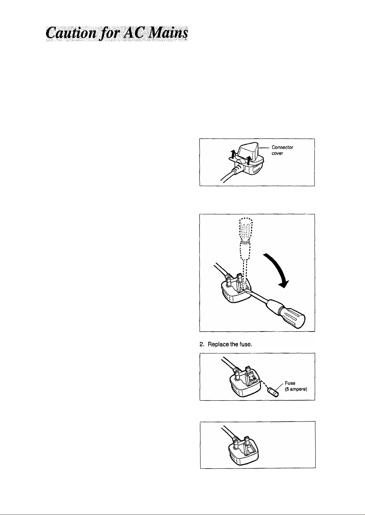
Before use
Remove the connector cover as follows.
How to replace the fuse
1. Open the fuse cover with a screwdriver.
If a new plug is to be fitted please observe the wiring
code as shown below.
If in any doubt please consult a qualified electrician.
IMPORTANT
The wires in this mains lead are coloured in accor
dance with the following code:
Blue: Neutral, Brown: Live.
As these colours may not correspond with the coloured
markings identifying the terminals in your plug, proceed
as follows:
The wire which is coloured Blue must be connected to
the terminal which is marked with the letter N or
coloured Black or Blue.
The wire which is coloured Brown must be connected
to the terminal which is marked with the letter L or
coloured Brown or Red.
3. Close the fuse cover.
Page 5

n Use a standard AC wall outlet
1. Use from an AC power source of high voltage, such as that
used for an air conditioner, is very dangerous.
A fire might be caused by such a connection.
2. A DC power source cannot be used.
Be sure to check the power source carefully, especially on a ship
or other place where DC is used,
9
Grasp the plug when disconnecting the power
supply cord
1, Wet hands are dangerous.
A dangerous electric shock may result if the plug Is touched by
wet hands.
2. Never place heavy items on top of the power supply cord,
nor force It to bend sharply. .
9
Place the unit where it will be well ventilated
Place this unit at least 10 cm (4") away from wall surfaces, etc.
9
Avoid places such as the following:
In direct sunlight or In other places where the temperature is
high.
In places where there Is excessive vibration or humidity.
Such conditions might damage the cabinet and/or other component
parts and thereby shorten the unit's service life.
9
Be sure to place the unit on a flat, level surface
If the surface is inclined, a malfunction may result.
9
Never attempt to repair nor reconstruct this unit
A serious electric shock might occur if this unit is repaired, dis
assembled or reconstructed by unauthorized persons, or if the
internal parts are accidentally touched.
9
Take particular care if children are present
Never permit children to put anything, especially metal, inside this
unit. A serious electric shock or malfunction could occur if articles
such as coins, needles, screwdrivers, etc. are inserted through the
ventilation holes, etc. of this unit.
9
If water is spilled on the unit
Be extremely careful if water is spilled on the unit, because a fire or
serious electric shock might occur. Immediately disconnect the
power cord plug, and consult with your dealer.
9
Avoid spray-type insecticides
Insecticides might cause cracks or "cloudiness" in the cabinet and
plastic parts of this unit. The gas used in such sprays might, more
over, be ignited suddenly,
9
Never use alcohol or paint thinner
These and similar chemicals should never be used, because they
might cause flaking or cloudiness of the cabinet finish.
9
Disconnect the power supply cord if the unit will not be used for a long time
If the unit is left for a long time with the power ON, this not only will
shorten its useful operation life, but also may cause other trouble,
9
If trouble occurs
If, during operation, the sound is interrupted or indicators no longer
illuminate, or if an abnormal odour or smoke is detected, immediately
disconnect the power cord plug, and contact with your dealer or an
Authorized Service Center.
Page 6
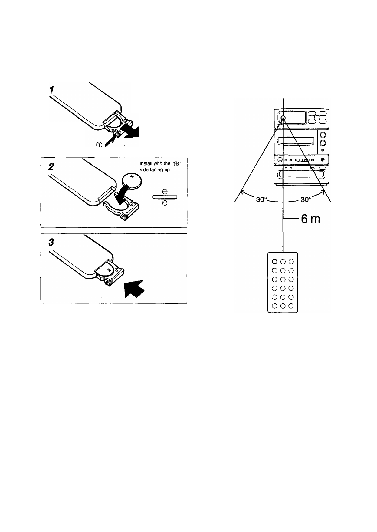
Installing the lithium battery
Remote control unites operation range
Reverse side of
remote control unit
While pressing the cover
in the ® direction, pull
it out in the @ direction.
Remote control signal sensor
To prevent damage to the lithium battery and electroiyte leakage:
• Install the battery with the ‘‘©” and "©” polarities aligned properly.
•Remove the lithium battery if you do not intend to use the remote
control unit for a long time.
• Do not throw a lithium battery into a fire, subject it to short-circuit
ing, disassemble it or apply heat to it.
The average life of a lithium battery is about one year.
It is time to replace the battery when the remote control unit will not
function even when It is operated close to the system.
How to use the remote control unit properiy:
•Do not place obstacles between the remote control signal sensor
and remote control unit.
• Do not expose the remote control signal sensor to direct sunlight or
to the bright light of an invertor fluorescent light.
•Take care to keep the remote control signal sensor and end of the
remote control unit free from dust.
To prevent malfunctioning of the remote control unit;
•Do not disassemble or remodel the unit,
• Do not place heavy objects on top of it.
• Do not leave it where it will be exposed to direct sunlight.
• Do not spill beverages or other liquids over it.
When the system is installed in a rack, the distance over which the
remote control unit can be operated may be reduced depending on
the thickness and color of the rack’s glass doors.
Page 7
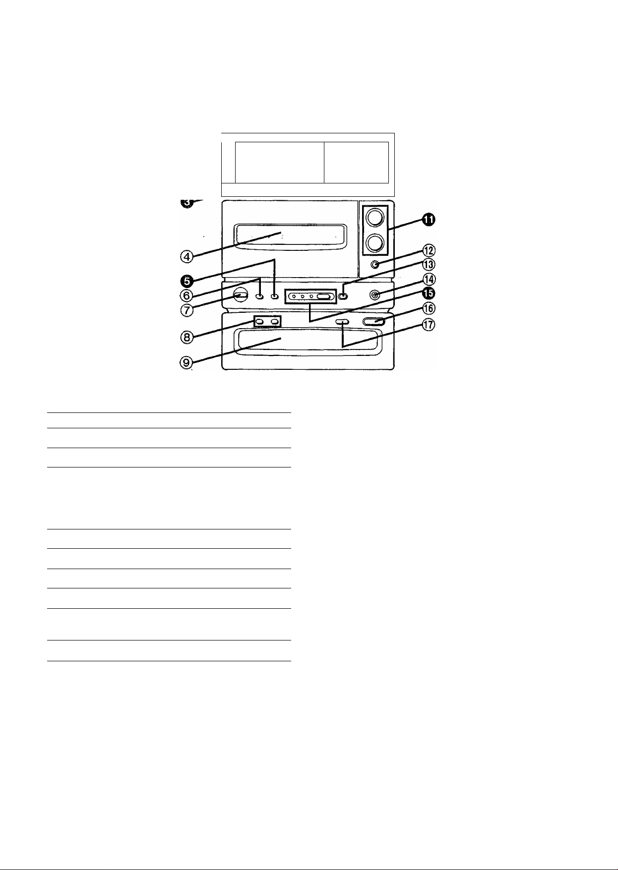
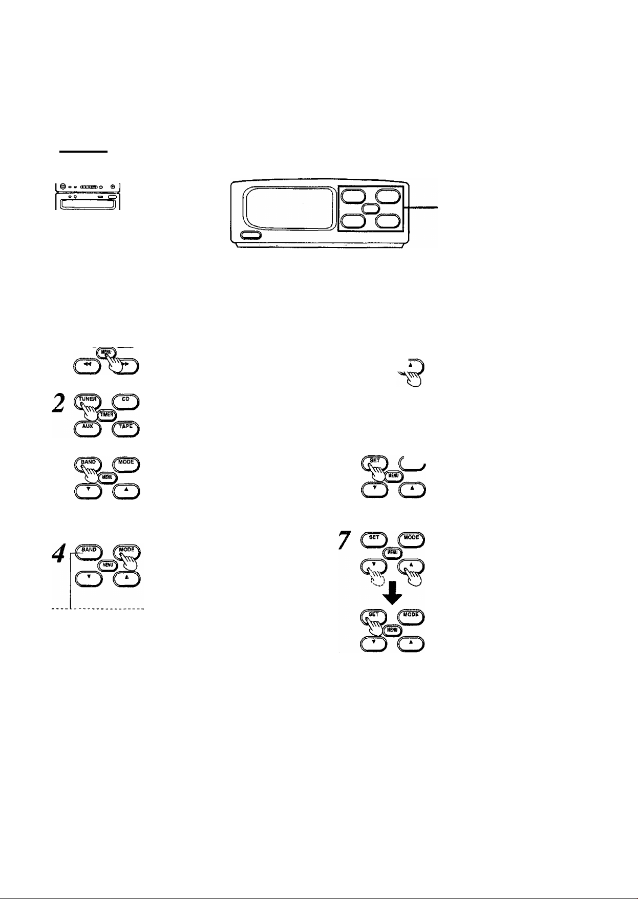
FriMt PMel
The buttons indicated by the white numbers on the black ground (for
example, O) can also be activated from the remote control unit.
rr""i
1
E.
No. Name Ref. page
® Display
@ Remote control signal sensor (SENSOR) 6
0 Power “standby c!)/ON” switch
(POWER, STANDBY c[)/ON) 10
Press to switch the unit from on to standby mode or vice versa.
In standby mode, the unit is still consuming a small amount of
power.
.................
10
j
o o
cit)
Jj
No. Name
@ Key operation section
(5-KEY OPERATION)
(D Volume controls (VOLUME)
® Timer ON/OFF button (0 PLAY/0 REC)
® Recording start/stop button
( Eng , START/STOP)
page
10
24
34
24
0 Cassette holder 20
0 Tape travel button (DIRECTION)
© Dolby NR ON/OFF button (DOLBY NR)
© Eject button (EJECT) 20
© Tape length input buttons
(TAPE LENGTH)
© Disc tray 16
20
20,24
24
(Q) Headphones jack (PHONES)
0 Sound menu button and indicators/
Beep orVoff button
(SOUND MENU, -BEEP OFF/ON) 22
Beep on/off function is available only on the main unit.
Disc tray open/close button
(OPEN/CLOSE)
@ CD edit button (EDIT)
22
16
24
Page 8
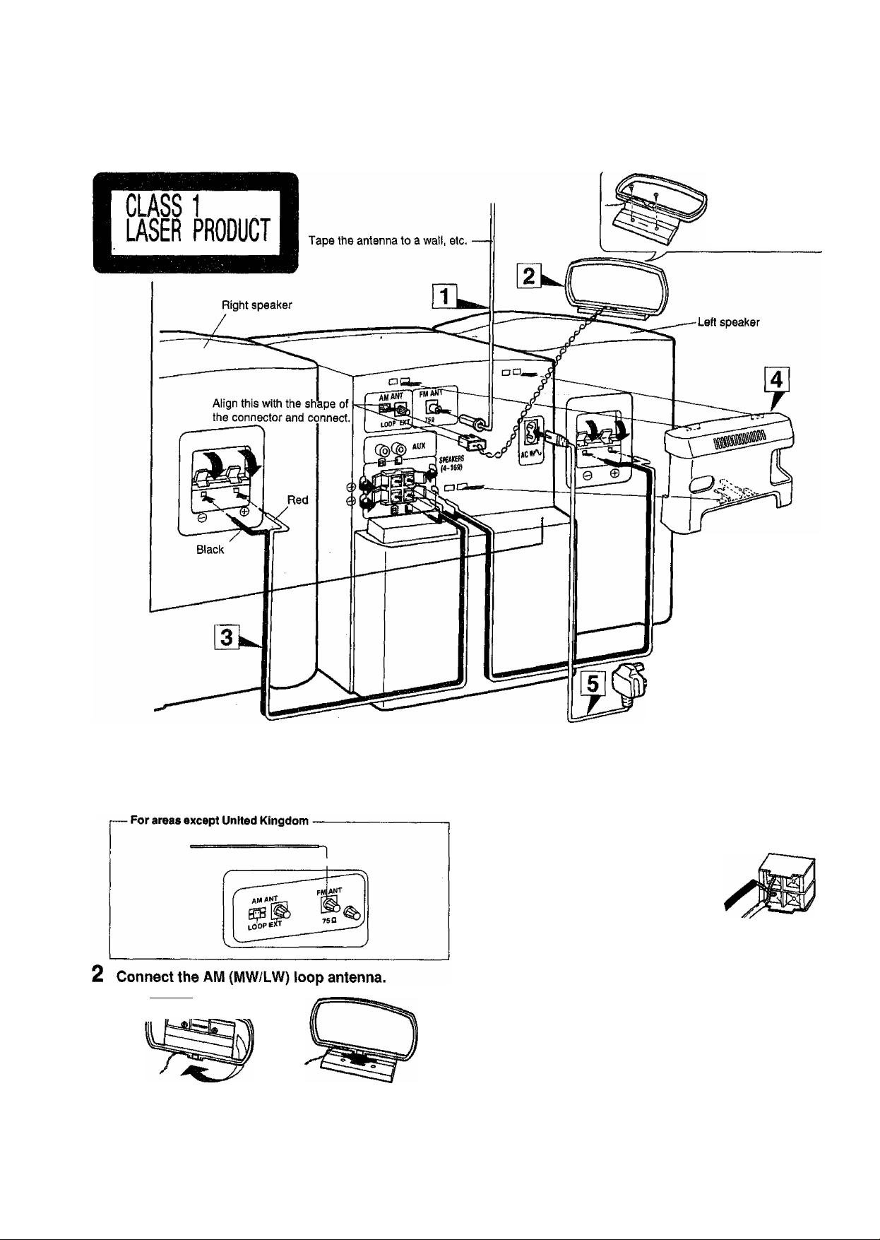
Cùhnedtions
Connecting the accessories
Use wood screws
from a hardware
store when attaching
the antenna to a wait,
etc.
1 Connect the FM indoor antenna.
Find a position on a wall or other surface where there is minimal
noise during reception and tape the antenna at that position. If
the noise level is high, it is recommended that an outdoor
antenna be installed. (See page 9.)
1. Assemble the AM loop antenna.
ESS
The configuration of the AC
power supply cord and FM
indoor antenna differ
according to the area.
Connect the speaker cables.
1. Twist the center conductor. If its
strands have become unraveled, twist
them tight again.
2. Connect the cables to the speakers.
Connect each of the cables to the
speaker terminal lever with the same
color.
3. Connect the cables to the system. To
prevent malfunctioning, do not shortcircuit the conductors.
=o
Connect the rear cover.
Poke the antenna cables through the hole in the left side of the
cover, and speaker cables through the hole in the bottom of the
cover.
FOR UNITED KINGDOM ONLY
BE SURE TO READ THE CAUTION FOR AC
MAINS LEAD ON PAGE 4 BEFORE PROCEED
ING TO STEP 5.
8
2. Connect the antenna to the system.
3. Find a position such as the top of the system or the area
behind a shelf where there is minimal noise during reception
and place the antenna at that position.
5 Connect the AC power supply cord.
Connect this cable last of all through the hole in the right side of
the rear cover.
Page 9
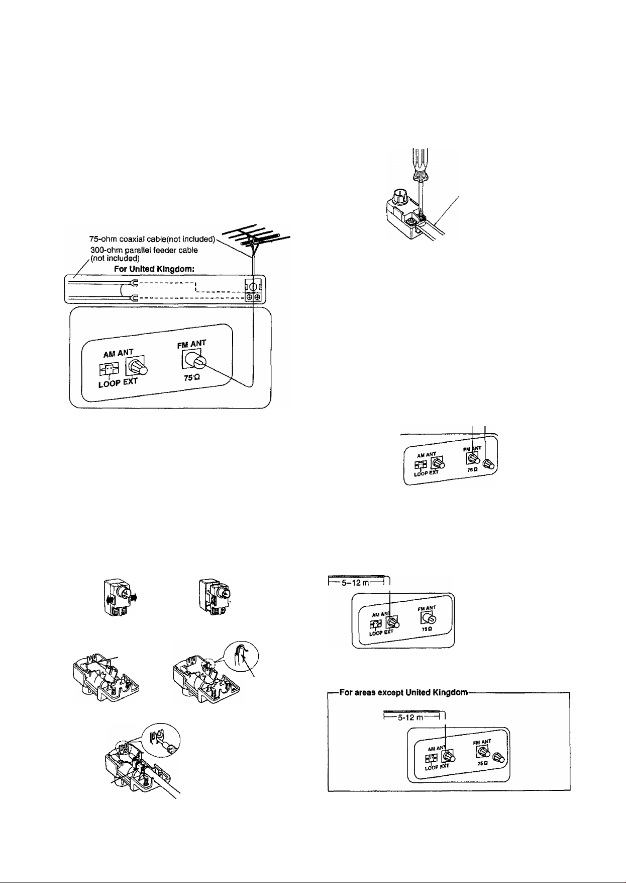
Connecting an outdoor antenna
'm
Wm
CmífiéctUf^
FM outdoor antenna {not included)
Disconnect the FM indoor antenna.
Two types of cable are most commonly used for connection from the
antenna; 300-ohm parallel feeder cable or 75-ohm coaxial cable. For
best resistance to external interference noise, we recommend you to
use the 75-ohm coaxial cable.
FM outdoor antenna
■ How to use the antenna plug (included)
(For United Kingdom)
Two types of wire are most commonly used for connection from the
antenna: 300-ohm parallel feeder cable or 75-ohm coaxial cable. For
best resistance to outside interference, the use of 75-ohm coaxial
cable is suggested.
rTo connect a 75-ohm coaxial cable-------------------
® Remove a piece of the outer vinyl insulator.
■>
Remove the cover while pulling the tabs.
Note:
If the tabs are pulled too hard, the casing may be damag
ed.
u
10 mm20 mm
rTo connect a 300-ohm parallel feeder cable-
300-ohm parallel
feeder cable
(not included)
Loosen the screw to connect the
feeder wire and tighten it to secure
the connection,
For areas except United Kingdom
1. Remove a piece of
the outer vinyl sheath
from the end of the cable.
2. Bundle the shield braid,
and remove a piece of
the inner vinyl sheath
covering the core wire.
3. Connect the core wire
and the shield braid.
CorewireU^MM ^Shield braid
30 mm
15 mm
AM (MW/LW) outdoor antenna
(vinyl-covered wire, not included)
This antenna is required in areas between mountains, inside rein
forced concrete buildings or other locations where the broadcast
signals are weak. Install the antenna along a window, etc.
Remove the lead wire and damp It with the plastic bar.
Pull out the
lead wire.
@ Install the coaxial cable.
Clamp the cable
conductor, and wind it
on so that it doesn’t
contact anything else.
Press down
with pliers.
(D Attach the cover.
Clamp the
lead wire to
the plastic
bar.
Do not disconnect the AM loop antenna.
Page 10
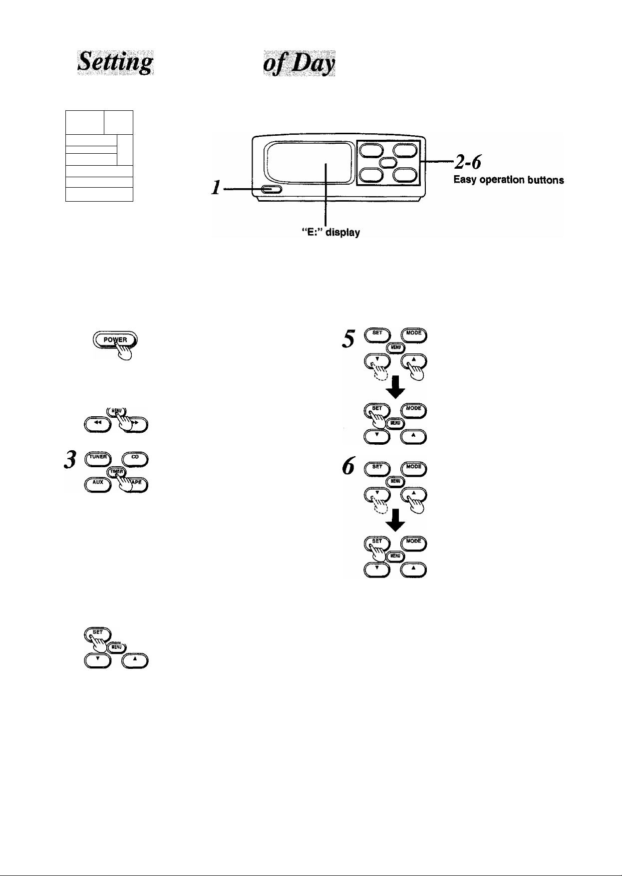
This is a 24-hour display clock.
L-
1,.
1
@ o o ®
OB Œ
k
........................... -..............
Example: Setting to 18:25;
o
o
0
1
....................................................
Press POWER.
When the easy operation buttons shows
same as at step 3, you can skip step 2,
2 Press MENU,
Press TIMER.
^ Press MODE once to display
T \
---------
¿_ASW “CLOCK”.
LL OCH
0:00
Within 4 seconds or so:
Press SET.
Flashes.
-Wo
When the display returns to the clock
display, press MODE again to display
"CLOCK”.
Press T or ▲ to set the hours.
-IB-OO
Press SET.
Press ▼ or A to set the min
utes.
IB: 05-
Press SET.
The clock now starts.
IBB5,
”E:” appears on the display when:
•The power cable Is connected to the power outlet for the first time.
•A power failure has occurred.
Follow the procedure above to set the time.
To display the clock when playing the source:
1. Press MENU.
2. Press TIMER.
The clock display now appears.
For your reference;
The hour digit or digits will not be incremented by one even when the
minute digits are changed from 59 to 00.
10
Page 11

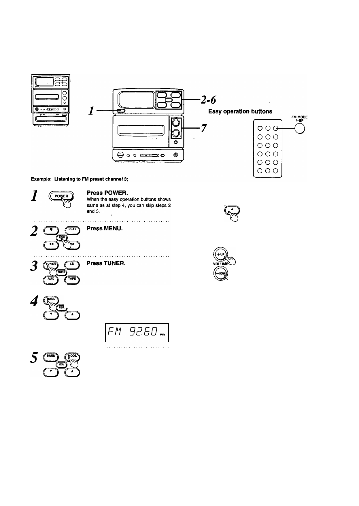
If broadcast frequencies are preset in the memory, you can easily
tune in any of these frequencies from the system or remote control
unit. (Up to 12 stations can each be set in the FM, MW and LW
bands.)
Automatic station presetting (auto memory)
.1, 13^
fT
3
L
Example: Presetting stations In the FM band;
J iff PLAYPress MENU.
Press TUNER.
Press BAND to select “FM”.
Each time this button is pressed "FM’
“MW" or "LW” is selected alternately.
Press MODE to select
“MANUAL”. (The button dis-
play~(P^.)
Each time tills DUtton is pressed, the dis
play changes as follows;
—^
---------
о о
) J
6
О
O '
О
1-6
Press T or A to locate the lowest frequency in the band.
FM; 87:50 MHz (0.05 MHz steps)
MW; 522 kHz (9 kHz steps)
530 kHz (10 kHz steps)
LW; 144 kHz (9 kHz steps)
Keep SET depressed 3 seconds or so.
FM BB. ID
Release the button as soon as "MEMO"
starts flashing.
Repeat these steps for all the stations
whose programs you want to listen to.
When this presetting is completed,
“MEMO" goes off and the station preset
last is tuned in.
\ I y
- MEMO-
^ I N
for
When you select
“MANUAL", the button
display change over
between “SET" and
“BAND".
MANUAL
t
MRNURL
■ PRESET <-
11
Page 12

To preset stations in the MW or LW band:
1. Perform steps 1 and 2.
2. Select "MW" or "LW" in step 3.
3. Performs steps 4 to 6.
To confirm which stations have been preset:
1, Press MODE to select "PRESET".
2, Press V or A .
Broadcast frequency
FM BB. IB'
Preset channel
•When another station is preset in a channel with a station already
preset, the previous station wifi be cleared.
•While making auto memory presetting, do not press any other
buttons on the unit.
Memory retention:
The presettings will be retained by the memory for about 2 weeks if
the power cable is left disconnected.
Preset the stations manually in the following
cases:
•When auto memory presetting is not possible due to weak signals,
etc.
•When the signals are so strong that frequency shifts
12
Page 13
Manual station presetting (manual memory)
CJgg
Example: Presetting FM 88.10 MHz in preset channel 3;
■1-7
1 Press MENU.
Press TUNER.
Press BAND to select “FM”.
Each time this button is pressed ‘‘FM’
“MW" or "LW’ is selected alternately.
FM B150
Press MODE to select
“MANUAL”. (The button 6\s~
play—f^.)
Each time this button is pressed, the dis
play changes as follows:
When you select
"MANUAL", the button !
display change over j
between "SET" and ;
"BAND". I
............................
¡MANUAL
'PRESET
j
5 Q
Press T or A to tune in the
station.
Lights when the station has been tuned
In properly. ^
FM BB. IB™
Lights when the broadcast is in stereo.
M№E^ Press SET.
FM BB IB
Press T or A to select preset
channel 3.
FM BB IB"!
Preset channel
While MEMO flashes:
Press SET.
To preset other stations, repeat steps 5 to 7.
\ I y
- MEMO- <TCneo
^11 N
i'
Flashes.
\ I /
> •> STEREO
• IffiMQ*
y I ^
STEREO
To preset stations in the MW or LW band:
1. Perform steps 1 and 2.
2. Select "MW” or “LW" in step 3.
3. Performs steps 4 to 7.
13
Page 14

Manual tuning (when stations have not been preset)
CZ3§€
C
0 o e 0
Example; Tuning in FM 88.10 MHz;
1................................................
2 C
When you select
“MANUAL”, the button
display change over
between “SET’ and
"BAND”.
14
Press POWER.
When the easy operation buttons shows
same as at step 4, you can skip steps 2
and 3.
Press MENU.
Press TUNER.
Press BAND to select “FM”.
Each time this button is pressed “FM”
"MW” or “LW” is selected alternately.
Press MODE to select
“MANUAL”. (The button dlsplay—
Each time this button is pressed, the dis
play changes as follows:
[MANUAL C
I I
PRESET «—I
O
MRNURL
BANo-4 Press ▼ or A to tune In the
station.
iT
K
Lights when the station has been tuned
in properly. I
Fh BB. I cm
STEREO
Lights when the broadcast is in stereo.
Press VOLUME to set the desired volume level.
-RBdB
Automatic tuning:
Keep ▼ or A depressed for about 1 seconds. The first station is
picked up and the tuning stops automatically.
•If the buttons are not released even when the display starts to
move, the tuning will not stop automatically even if stations are
picked up.
•Ambient interference may cause the tuning to stop without picking
up any stations.
To stop tuning at any time:
Press the button again.
Frequency steps:
The frequency changes in the following steps:
0. 05.MHz steps for FM
9 kHz or 10 kHz steps for MW
9 kHz steps for LW
MW allocation settings:
This unit comes equipped with an electronic digital tuner that divides
the broadcast band into many small steps. These steps match the
assignable broadcast frequencies and Intervals in between.
Each country allocates (assigns) broadcast bands according to their
particular needs.
By adjusting the allocation, you can enable this tuner to receive MW
broadcasts allocated in 10 kHz steps.
1. Perform steps 1-3.
2. Select "MW” in step 4.
3. Press and hold BAND for approximately 3 seconds.
To return to the original indication, repeat steps 1 to 3 above.
Page 15
■■'J'HWr
Listening to preset stations (preset tuning)
ifuo^ Press T or A to select the pre-
set channel.
Press BAND to select “FM”.
Each time this button is pressed “FM"
“MW" or "LW” is selected alternately.
Press MODE to select
“PRESET”.
Each time this button is pressed, the dis
play changes as follows:
EH BB. IB'
Preset channel
Press VOLUME to set the desired volume level.
- BBdl
When noise interferes with FM stereo
reception:
(Available only from the remote control)
FM MODE
/-BP
Press FM MODE once.
FM BB //7"f
The noise is reduced, making it easier to
listen to the program.
Lights.
MANUAL
t_
•PRESET-
J
You cannot preset FM stations in monaural mode.
PRESE J
15
Page 16

v:;' l'Ìì:
■ V.
Sequential play
:;y' '''ii:;:;"^''i'"
Easy operation buttons
(fi).
— .
0 O 0
o o o
O 0 o
“"cT?) o
o o o
o o o
1
CD
Press POWER.
When the easy operation buttons shows
same as at step 6, you can skip steps 2
and 3.
Press MENU.
Press CD.
NO 015C
This indicates that a CD has not been
installed.
Press OPEN/CLOSE and insert
the CD with the label surface
facing up.
[^+UP
VOLUMI
Press PLAY.
Track number now playing
no /.
Elapsed time of track
Play continues in the original track order
from track no. 1 to the final track and then
stops automatically.
Press VOLUME to set the
desired volume level.
To stop play at any time:
Press
To Stop play temporarily:
(Available only from the remote control)
Press II.
16
An adaptor for CD singles is not required.
Press OPEN/CLOSE to close
the tray.
Total number of tracks
Total play time
70 hTTJ
CDSlISSiBltBQIISISOQQ^
To play the disc again, press PLAY on the system or CD on the
remote control.
Total play time indicated:
The total play time including the gaps between the tracks is indi
cated. This is why the time may be several seconds longer than the
figure given in the liner notes, etc.
When ^ appears:
This indicates that the CD has 13 or more tracks.
For your reference:
•When a CD is installed and PLAY Is pressed, the tray closes
automatically and play begins.
•When CD play is switched midway through to the radio or tape
play, CD play will stop automatically.
Page 17

■; .:.;S
CZIgg
3
Skipping tracks (skip function)
To skip forward:
Press ►►/►►!.
You can skip as many tracks ahead as
the number of times you press the
button.
During play;
Tracks are skipped and play com
mences,
During pause:
Tracks are skipped and operation stops.
During stop:
You can skip to the beginning of the de
sired track. (The display will return to the
previous setting in 5 seconds.)
To skip backward:
«EMIJ
For your reference:
During program piay, the number of tracks wili be skipped in the
forward or backward direction in the order in which the tracks have
been programmed.
Press .
You can skip back to the beginning of the
track being played.
During play:
When the button is pressed once, the
pickup moves to the beginning of the
track being piayed.
When it is tapped repeatedly, the pickup
skips as many tracks as the number of
times you press the button, and play
commences.
During pause:
Tracks are skipped and operation stops.
During stop:
You can skip back to the beginning of the
desired track. (The display will return to
the previous setting in 6 seconds.)
ООО
ООО
ООО
-ООО
ООО
ООО
Searching tracks (search function)
To search forward during play:
Press and hold .
Release the button when you have ar
rived at the desired position.
Ш О
To search backward during
play;
Press and hold (44/^.
Release the button when you have ar
rived at the desired position.
For your reference:
During program play, the search will extend only to the beginning or
end of the track being played.
To repeat play (repeat function)
(Available only from the remote control)
Press O before or during
play-
_____________________
10 001
CJ>
I
Lights.
To release:
Press the button again.
For your reference:
•During program play only the programmed tracks will be played
repeatedly.
•When only one track has been programmed, the same track can
be heard over and over again.
17
Page 18

IJst€ning to C0mp<^ i
Starting play from a desired track
L-J
° ° °
.....
o
rS
o
0
e
Press MENU.
11-----n
tr- '
----
@ a a 1.11 = 10
t'-—
Example: Starting play from track no. 8;
1-4
18
All the tracks are played in the original
track order starting with the one selected
and ending with the final track, and then
play stops automatically.
Page 19

::;ÍÍSisÍ;S||iÍ|IÍ||5|||sÍ^
Listening to programmed tracks (program play)
(Available only from the remote control)
Up to 18 tracks can be programmed.
Example: Programming tracks 8,1 and 5 in this order;
Press CD.
Press ■.
Press PROG.
BO Bill
PROORMI
I
Lights.
Press P>l or K4 to select the
desired track.
Within 5 seconds or so,
Press PROG.
The programming is now entered.
Programmed track number
Repeat steps 4 and 5 to pro
6
7
When “FULL” appears on the display:
This indicates that an attempt has been made to program more than
18 tracks. No more than 18 tracks can be programmed.
When “—:—” appears on the display:
This indicates that the total play time of the programmed tracks
exceeds 99 minutes and 59 seconds.
However, program play is still possible.
For your reference:
•What has been programmed is retained in the memory untii
cleared. Unless the disc tray is opened or closed, the programming
will be retained even when play is stopped or the power Is switched
off.
•The programming is retained for about 2 weeks when the power
cord is disconnected.
gram the other tracks.
Press CD.
When the programmed tracks have all
been played, play stops automatically.
To release the program play
function:
Press PROG, in the stop mode.
This function Is released by pressing ■
even while play has stopped.
Programmed track sequence
n? B-0 Í
Total play time of programmed tracks
B BB3
19
Page 20

Normal, chrome and metal tapes can be used.
£Z3§g
L.
..........
I
6
4
Press POWER.
When the easy operation buttons shows
same as at step 8, you can skip steps 2
and 3.
Press MENU.
8 Q
DIRECTION
%
Press DIRECTION to select the tape travel direction.
►: Tape play starts with the forward
side of the tape.
Tape play starts with the reverse
side of the tape.
ICBLiVSHftl O VOLUME
► mnV'"? .
Tape direction display
To start play from the reverse side, take
up the tape onto the other reel before
playback.
Press PLAY.
Play Is repeated until ■ is pressed.
o
Press VOLUME to set the desired volume level.
20
DOLBY NR
«
Press DOLBY NR to set the Dolby NR system on or off.
Lights.
This should be off when the recording
has not been made using the Dolby NR
system.
” HBd 1
To stop playback at any time:
^ Press ■.
For your reference:
When tape play Is switched midway through to the radio or CD play,
tape play will stop automatically.
Page 21

To find the start of a program during
playback
i—
0
^ J
0
0
@00 <1 * IB in S
Ic;-
-----------------
^
To fast forward or rewind the tape
[When > (forward side) appears as the tape direction]
To skip to the start of the next
O
program during playback:
Press
To skip to the start of the pro
gram being played:
Press
Press the reverse button to that indicated in the text when ◄ (re
verse side) appears as the tape direction.
BBBa
The unrecorded intervais between the programs are used to search
for programs. This function may therefore not operate properly in the
following situations:
•When the unrecorded intervals between programs are less than
4 seconds long
•When there is no dead space on the tape (because the recording
has been made from a microphone, etc.)
•When there are parts recorded at a very low level or silent pas
sages during a program (classical music, etc.)
•When less than 10 seconds have elapsed since the beginning of
the program or when less than 10 seconds remain until the start of
the next program
•When a tape has been recorded with fade-ins and fade-outs
[When > (forward side) appears as the tape direction]
^pcay^ To fast forward the tape in the
O^ stop mode:
Press
To rewind the tape in the stop
mode:
Press
Press the reverse button to that indicated in the text when < (re
verse side) appears as the tape direction.
21
Page 22

(Available only from the remote control)
i':'. i'11? ■;
To temporarily reduce the volume level
(muting)
(Available only from the remote control)
ooo
EASY PLAY
lo 0 Oh
ooo
ooo
ooo
ooo
tf a CD or tape is already installed, the power is turned on and play
begins automatically from the power-standby condition simply by
pressing a button.
H H ©
To listen to the radio:
Press TUNER/BAND.
The radio receives the station which was
last received.
To listeh to a CD; Press CD.
Play starts from track #1.
To listen to a tape:
Press TAPE.
Playback starts from the tape side which
was last played.
ooo
ooo
ooo
ooo
ooo
ooo
Press MUTING.
This comes in handy when you need to
answer a telephone call, for instance.
Lights.
To release the muting:
•Press MUTING again.
•Reduce the volume, set to “— dB" and
then set the desired volume level.
To turn off the operating beep tone
Keep -BEEP depressed for about 2 seconds.
A beep is heard, indicating that the beep
tone has been turned off.
Volume level heard during play:
The sound of the program or track is faded in (it gradually becomes
louder) to the level set before the power was turned off.
E!l3S
Fade-in does not occur when the power was already on.
To turn the beep back on:
Keep -BEEP depressed again.
To listen through headphones (not included)
•Turn down the volume before connect
ing the headphones.
•Avoid listening for prolonged periods of
time to prevent hearing damage.
©-
Cl]
•Plug type used: Stereo mini
Be sure not to prevent the compact disc
tray from opening or closing.
PHONES
22
Page 23

a
Notes on tapes:
Normal, chrome and metal tapes can be used (for recording and
playback),
•This system automatically identifies the type of tape being used
and sets the bias (for recording) and equalizer.
•The recording level is set automatically.
Run the leader tape past the heads and set up the system so that
recording can be commenced immediately. (This is not necessary
when edit-recording CD tracks.)
How to run the leader tape past the heads:
Magnetic section
(on which sound can be recorded) ■
Leader tape (on which sound cannot be recorded)
When “ERROR*’ appears on the display during recording operation:
It means that the tape is not installed, or you install the tape which
has no erasure prevention tabs.
Using Dolby NR reduces tape hiss in the high-frequency range. It
boosts the level of the high-frequency program content during re
cording, and lowers it by the same amount during playback, simulta
neously reducing high-frequency noise Incurred during the recording
process.
B type;
Noise is reduced to about 1/3. Use this type when playing a tape in
the Dolby NR mode.
Notes on CD recording methods:
There are 3 methods. Choose the one that best suits your needs.
To edit tracks on a CD in their original
sequence (see pages 24-25)
•Tracks are not interrupted at the end of the tape.
•A blank section can be left at the end of the tape.
Blank section
Side A
Side В
Track 1 2
3 4
To edit a collection of CD singles on one tape
(see page 26)
•This function can be used to record further tracks on the part of the
tape which is still free after all the tracks of a CD have been
recorded.
•Tracks are interrupted at the end of the tape side B.
•A blank section can be left at the end of the tape side A.
Side A
First CD Second CD Blank section
Track 1
I I I
2 1
. [
Dolby noise reduction manufactured under license from Dolby
Laboratories Licensing Corporation,
"DOLBY" and the double-D symbol tU are trademarks of
Dolby Laboratories Licensing Corporation.
If you record with your desired sound field or tone quality, it is not
effective to the recorded sound.
Side В
1
_________________
Third CD
2 1
) I
______________
Fourth CD
I
To record tracks without the editing function
(see pages 28-29)
•This function can be used to record from midway through a pre
viously recorded tape.
•Tracks are interrupted at the end of the tape.
•A blank section cannot be left at the end of the tape.
Side A 11 Track 1
Side В
Remainder of track 5
23
Page 24

Editing CD tracks in their originai order
Up to 36 tracks can be edit-recorded.
The tape is automatically forwarded to the position where the tracks
can be recorded,
7
6
ItTW
START/STOP
■ V
EDIT
■TAPE LENGTH+
(EDIT)
Press MENU.
Press EDIT.
The length of tape required for all the
tracks to be recorded now appears on
the display.
Lights.
Press “ or + to Indicate the length of the tape used.
8
EJECT
D0L8Y NR
%
liTEfl
START/STOP
Press EJECT and insert the tape.
When the editing starts, the cassette
deck automatically advance the tape to
which the recording can be made.
Press DOLBY NR to set the Dolby NR system on or off.
L IWT I
(SBiQiBisiiiiizia)
O VI
Lights.
This should be off when the recording is
not going to be made using the Dolby NR
system.
Press REC.
ATLS (see next page) starts automati
cally and when ATLS has been com
pleted, edit-recording begins.
iiO
S) HI IS IB IS Bl
IBOLBVBIIB V
on
It takes a little while (approx. 70 sec
onds for a 60-minute CD) after the
button Is pressed for the recording to
actually start.
24
/_ “ Hb
Use a tape which is longer than the CD's
total play time,
Your attention is drawn to the fact that recording pre-recorded
tapes or discs on other published or broadcast material may
infringe copyright laws.
Page 25

To stop edit-recording at any
time:
1. Press REC.
The CO play is stopped automatically
as well.
2. Press ■ to indicate "CLEAR” on the
display.
What is the ATLS function:
"ATLS" stands for Automatic Tape Level Setting, and It refers to the
function which automatically sets the recording level. No sound is
heard while ATLS is operating.
1. It scans the tracks on the CO and finds the point with the maxi
mum sound level.
2. It sends the peak signal to the cassette deck section and auto
matically sets the recording level.
3. Recording now starts.
When edit-recording Is completed:
Both the CD and tape stop automatically.
The LINK display indicates that tracks on. another CD can .be re
corded on the remainder of the tape.
Proceed to step 2 on page 26.
To program and edit-record desired tracks only:
1. After step 3, press PROG, on the remote control unit.
2. Select the desired tracks using or
3. Within 5 seconds, press PROG, on the remote control unit and
enter the programmed tracks.
You can edit up to 18 tracks.
4. Perform steps 4 to 8.
•Use a tape which is under 99 minutes In length. A long blank
section may be left on the top side if a tape longer than this is used.
•It is not possible to edit-record the tracks on a CD containing 37 or
more tracks. ("ERROR” display will appear.)
In this case, record without edit function.
(Synchro recording—see page 28.)
25
Page 26

■■ ■■ ■ ■
,;j- s'1 ' V 'v'' ,'s^. ■
Editing a collection of CD singles on one tape (link function)
L
O O ‘o
¿~eg)<L
Pll
Ijll
■V 'i'' ■:
- V',,
Easy operation buttons
BBS
START/STOP
4
■ 2
:V'
EDIT
Complete the edlt-recording of
the first CD by following the
procedure on page 24.
Check that the LINK display has ap
peared.
Time remaining
REM ions
_______
I EOn I Isibt Bl
Press OPEN/CLOSE and re
place the CD.
^ e:/7
Press EDIT.
The remaining time will appear.
\ I y
Flashes.
\ I ✓
" LINK -
/ I ^
t
israa
START/STOP
START/STOP
3
Press REC.
Edit-recording commences when ATLS
has been completed.
To record tracks from the third or subsequent CD:
Repeat steps 2 and 3.
To stop the link function at any time:
1. Press REC.
The CD play is stopped automatically
as well.
2. Press ■ to indicate "CLEAR" on the
display.
26
Do not press PLAY. When you press
PLAY by mistake, record the 1st CO over
again.
REM 959
Page 27

liSiliilliEllliSilSiEii#
When “LINK” doesn’t appear;
1. Press EDIT.
2. Press ■ to indicate ‘‘CLEAR" on the display.
3. Make an edit-recording from the first step.
To program the desired tracks and link them:
1. After having edit-recorded the first CD, press OPEN/CLOSE and
replace the CD.
2. Press PROG, on the remote control unit, and select a desired
track using or
3. Within 5 seconds, press PROG, on the remote control to enter
what has been programmed.
4. Press EDIT.
5. Press REC.
When “OVE” appears on thé display düring
linking:
This indicates that the length of even the shortest track on the CD
exceeds the remaining time on the tape.
Program a track which is shorter than the remaining time (see "To
program the desired tracks and link them;" above), or press ■ to
release the link function.
27
Page 28

Recording without the edit function (synchro recording)
2
1
usa
START/STOP
EJECT
DOLBY NR
1
DIRECTION
j^LAY^ Press MENU.
Press EJECT and insert the
tape.
Press DOLBY NR to set thè Dolby NR System on or off.
Set this off whsn thè recordtng is not
going to be macie using thè Dolby NR
System.
Press DIRECTION to select the
tape travel direction.
► : The tracks are recorded on the top
◄: The tracks are recorded on the
side of the tape and then on its
reverse side.
reverse side only.
^AU)^ ^TAPE^
Gsa
START/STOP
Press CD.
Press OPEN/CLOSE and in
sert the CD.
Press the button again to close the tray.
Press REC.
CD piay starts automatically and record
ing commences.
Q] SMS 01 IS m
o
28
Page 29

; v: fefjf
" л :■'кviS-®‘5-i;
шя
START/STOP
To stop recording at any time:
Press REC.
CD piay also stops automatically.
To create unrecorded inter-
^ vals for search operations:
Press ■.
The cassette deck section creates an Interval lasting for 4 seconds
and then stops.
To program and record the desired tracks:
1. After step 6, press PROG, on the remote control unit.
2. Seiect a desired track using or W^.
3. Within 5 seconds, press PROG, on the remote control unit and
enter the programmed tracks.
You can record up to 18 tracks.
4. Press REC.
29
Page 30

EJECT
Press EJECT and insert the tape.
Press TUNER.
DOLBY NR
%
DIRECTION
1
Press DOLBY NR to set the Dolby NR system on or off.
IDHJVKHtfl
<
Lights.
Set this off when the recording is not
going to be made using the Dolby NR
system.
VOLUME
„.limi
NN* V <
«MM 1
Press DIRECTION to select the
tape travel direction.
►: The broadcast is recorded on the top
side of the tape and then on its
reverse side.
The broadcast is recorded on the
reverse side only.
IMLBVflWm o VOLUME
Tape direction display
Press MENU.
1
Press BAND to select “FM”, “MW” or ”LW”.
Each time this button is pressed "FM",
"MW" or "LW” is selected alternately.
FM 8150*
BAND^ Press T or ▲ to tune in the
radio station.
Press REC.
nHnavjiHi^^O
Flashes.
Press REC.
8
neiu
STARTraTOp
SS9 To stop recording at any time:
30
Page 31

Recor^g
's'
Eliminating unnecessary parts;
Press REC during the recording.
To resume recording:
Press REC again.
To erase a previous recording on a tape:
When a new recording is made on an already recorded tape, the
previousiy recorded sound is automaticaiiy erased.
To erase all the sound on a tape:
1. Press MENU.
2. Press TAPE.
3. Press EJECT and place the tape in the holder.
4. Press DIRECTION to select the side of the tape whose sound is
to be erased.
5. Press DOLBY NR to turn the Dolby system off (turn off the
display).
6. Press REC.
When noise interferes with MW or LW
reception during recording
(Available only from the remote control)
FM MODE
/-BP
o o o
o o o
o
o o o
o o o
o o o
o o o
FM MODE
/-BP
Keep ~BP depressed for about 3 seconds.
IP I
IP
L
3P 3
The position where there is less noise is
seiected.
31
Page 32

"SoLind field” refers to the combination of the sound {or tone) quality
curve and surround effect. It enables you to fit your favorite music in
with the occasion in your life.
Using the sound field effects and tone
quality curves
Three different kinds of sound fields and tone quality curves have
been preprogrammed in the memory.
Press SOUND MENU to select a setting.
Each time this button is pressed, the setting is changed in the
sequence of WIDE^HEAVY^NIGHT^Iight off (FLAT), after which
WIDE is selected again, and so on. ■ •
Boosting the ultra bass (V,BASS) sound
(Available only from the remote control)
Lights.
SOUND MENU
Htm MiOHT
:^o o
SOUND MENU
WIDE DEiWHIQMT
SOIWOMENU
ME
o o:^-.
SOUND MENU
WIDE HMVYWKIHT
[o o o
Select WIDE.
This creates a sound with a wide, farreaching feel.
Select HEAVY.
This creates a heavy bass sound.
Select NIGHT.
This creates a sound with the same clar
ity at a high or low volume level.
To release any of these set
tings:
Press the button to light off the indicator
(FLAT).
V.BASS
The ultra bass sound effect cannot be recorded. Its effect is added
only to the sound heard through the speakers.
To release:
Press the same button again.
32
Page 33

fc. . '!.' '\- J-. ■^ •■! ■'
First, complete the procedure given in "Setting the Time of Day” (on
page 10).
The timers are used on occasions such as these.
Flay timer (see pages 34-35)
Use this timer to wake up to the sound of music (CD, radio or tape)
instead of an alarm clock.
The sound source of your choice is played at the selected volume at
Record timer (see pages 36-37)
Use this timer to record radio programs aired while you are out or
asleep.
The radio program you want to hear is recorded at the assigned
time.
Sleep timer (see page 38)
Use this timer to allow yourself to drop off to sleep while listening to
music (CD, radio or tape).
The system will go into standby mode at the assigned time.
The recording wilt be made
while you are out.
You can derive even greater convenience from the timer functions
by using them in combination. (See page 39.)
You can fall asleep while listening to music and wake up to the
sound of music the next morning.
You can fall asleep while listening to music and record a late-night
program.
33
Page 34

Example: Playing a CD at a —48 dB volume level from 6:30 to
7:40;
Press MENU.
Select the sound source.
•When you select CD:
Install a CD (or tape).
When you select TAPE:
Install a tape.
Press TIMER.
[HERJ
AÔÎ^X^TAPE"
Press MODE twice to display
“H PLAY” and then press SET
within 4 seconds or so.
ON 000
ON
ON -,am
Flashes.
^ Programming the play start
^ ^—&—'(ON)time:
0 Press T or A to select the
hours.
34
4^ Q
[+UP
VOLUM
f-'-i
Press VOLUME to set the vol
ume of the sound you will be
awakened by.
Press MENU.
ON -ßJJO
Press SET.
Press T or A to select the
minutes.
ON EßO-
0 Press SET.
I
ON
cm I
✓ \
Page 35

iiimi
' if"''
10
SET \ ^MODE^ Programming the play end
(OFF) time:
O Press T or A to select the
hours.
HO C -~ l'n
ui I ■ ■ ' '
-JJJD
' \
OFF
Press SET.
rwoDe^ (D Press T or A to select the
minutes.
--------------
OFF IHD-
OFF I
0 Press SET.
[spuAY/nREc Press 0 PLAY/H REG.
looa
SPLAY
Lights.
Check that "Ca PLAY” has appeared on
the display.
Press POWER.
The sound is faded in and piay starts at
the programmed time.
✓ N
HPLAY/BREC
To release:
(When you seiect CD or TAPE)
Press S PLAY/ca REC once to turn off
m PLAY.
Each time this button is pressed, the dispiay changes as foiiows:
PLAY“
□
-off (-
(When you select TUNER)
Press □ PLAY/Ca REC twice to turn off
□ REC.
Each time this button is pressed, the dispay changes as follows:
m PLAY—y[3 REC
'
---------
off <
-----
’
The timer does not operate but the pro
grammed times will be stored in the
memory.
To check what has been programmed:
(Only when “[g PLAY” is on)
1. Press MENU.
2. Press TIMER.
3. Press MODE twice to display "H PLAY”.
The start time, end time, source and wake-up volume level are
displayed in sequence for about 3 seconds each.
To change what has been prbgrammed:
Repeat the procedure starting with step 1.
When “0 PLAY” appears on the display, press 0 PLAY/0 REC to
go off “0 PLAY” on the display, and repeat the procedure starting
with step 1.
To use the play timer with the same timer setting:
1. Select the sound source, and set the volume of the sound you will
be awakened by.
2. Press 0 PLAY/0 REC and appear “0 PLAY” on the display.
3. Press POWER and set the system to the standby mode.
To enjoy music or a program after programming:
1. start playing the music or listening to the program after step 9.
Even if the volume or sound source is changed, whatever has
been programmed will be restored at the wake-up time.
2. After finishing with the music or program, press POWER and set
the system to the standby mode.
•The timer will not work if the power is kept on.
•When the power is switched to the standby condition during timer
play, the play end time programming will be ignored even if the
power is turned back on and piay resumed.
•The play timer and unattended recording timer cannot be used in
combination.
For your reference:
Unless it is released, the wake-up timer will operate every day in
accordance with what has been programmed.
35
Page 36

CJgg
0 a s (ITtaiO ©
1-10
12
C
Example: Recording a program from a broadcast station stored
in FM preset channel 3 from 18:30 to 20:00;
Press MENU.
co-i Press TUNER.
«Install the recording tape.
•Select the Dolby NR position.
•Select the tape travel direction.
^ Press BAND to select “FM”,
“MW” or “LW”.
^ Each time this button is pressed “FM”,
“MW or “LW” is selected alternately.
i Press MODE to select PRE
SET.
aPLAY/fflREC
11
Press MODE three times to
MEMj display “El REC”, and then
A press SET within 4 seconds or
so.
uN
ON
I
CD
SEt“^ i Programming the play start
(ON) time:
0 Press T or ▲ to select the
ON
hours.
-Aoo
Flashes.
0:00
36
ISn^ Press T or A to tune in the
station.
Press MENU.
CD Press TIMER.
IMEB
AUX ^S^VAPE''
ON -IBOO
Press SET.
minutes.
0 Press SET.
ON IB30-
OH I
/ s
Page 37

■ Using the ^€0
1 jf SET ^MODE"^ Programming the play end
(OFF) time:
/^=T=\ r 4 \ © Press ▼ or A to select the
hours.
0FFE0:30
Press SET.
SET-^ iTMODE^ (3) Press T or A to select the
minutes. ■
OFFFIJDO-
QFF I
0 Press SET.
KPLAY/EiREc Pross 0 PLAY/E] REC.
11
X
< ■ >
^ \
To check what has been programmed:
(Only when “0 REC” is on)
1. press MENU.
2. Press TIMER.
3. Press MODE three times to display “0 REC”,
The start time, end time and radio band are displayed in se
quence for about 3 seconds each.
To change what has been programmed:
Repeat the procedure starting with step 1.
When “□ REC” appears on the display, press 0 PLAY/0 REC to
go off “0 REC” on the display, and repeat the procedure starting
with step 1.
To use the record timer with the same timer setting;
1. Select the band and desired preset channel, and set the volume
of the sound you will be awakened by.
2. Press 0 PLAY/0 REC and appear "0 REC” on the display.
3. Press POWER and set the system to the standby mode.
To enjoy music or a program after programming;
1, Start playing the music or listening to the program after step 11.
Even if the sound source is changed, whatever has been pro
grammed will be restored at the unattended recording time.
2. After finishing with the music or program, press POWER and set
the system to the standby mode.
After listening to a tape, check that the recording tape has been
installed in the holder.
12
Qrec
Lights.
Check that “E REC” has appeared on
the display.
Press POWER.
At the programmed time recording com
mences automatically with the sound
muted. To hear the sound, press VOL
UME.
oiPLAY/QREc To relcase:
Press 0 PLAY/0 REC once and turn off
”0 REC”.
Each time this button is pressed, the dis
play will indicate the following;
0 PLAY->0 REC
1—0« J
The timer does not operate but the pro
grammed times will be stored in the
memory,
/10 CL
•The timer will not work if the power is kept on.
•When the power is switched to the standby condition during timer
recording, the recording end time programming will be ignored
even if the power is turned back on and recording resumed.
•The unattended recording timer and wake-up timer cannot be used
in combination.
For your reference:
The record timer will be automatically cancelled after it has activated
once.
37
Page 38

iL ■ ■' ■ --j
@ <3 a tOlTSDO e
Example; Switch the system to the standby condition in
O
o
0
as D CD
iJ
30 minutes;
—
rr
1
n n
o o
o
■>
1-4
SLEEP
5
SLEEP
00 O
o o o
o
o o o
o o o
o o o
o o o
(Available only from the remote control)
AUX^ V''YAPE
PLAv^ Press MENU while listening to
the sound source.
/T№
Press TIMER.
P*"®®® MODE four times to dlspiay “SLEEP” and then press
SET within 4 seconds or so.
-E-OO
Press T or A to select the
desired time.
Press SLEEP.
Check that “SLEEP” appears on the dis
play.
0-30
SLEEP
To change the time remaining during operation:
Repeat the procedure starting with step 1.
To use the timer with the same setting:
Press SLEEP on the remote controi unit to dispiay "SLEEP”.
To release:
(Available only from the remote control)
Press SLEEP to turn off “SLEEP”.
The timer does not operate but the
programmed time wiii be stored in the
memory.
38
-0:30-
Press SET.
Page 39

To fall asleep while listening to an FM
program and wake up to the sound of a
CD the next morning
(see pages 34-35 and 38)
1. Program the play timer (CD).
2. Tune in the station and adjust the volume.
3. Program the time at which the power is to be switched to the
standby condition using the sieep timer.
To fall asleep while listening to an CD
program and then record a late-night
program (seepages 36-37 and38)
1, Program the record timer.
2, Piay the CD and adjust the voiume.
3, Program the time at which the power is to be switched to the
standby condition using the sieep timer.
(Make sure that the power is switched to the standby condition
before the record timer is due to commence.)
Sequence of priority among the timers
When the times programmed in the timers overlap, the sleep timer
takes precedence over the wake-up and unattended recording
timers.
Program the times so that they do not overlap.
39
Page 40

Enjoying the functions of other units
1-2
Recording the sound of another unit on the system’s tape
ijigB
START/STOP
Example; Listening to records;
Press MENU.
Press AUX.
Run
Start playing the sound
source.
Refer to the Instruction Manual of the unit
connected.
External unit connection:
Connect an external unit, such as audio tape deck (for playback
only) or output terminals of a VCR or TV (not included).
Video cassette recorder
(not included)
Example: Recording records;
1....................................
PLAv-i perform steps 1 to 3 on
page 30, and then press
MENU.
Start playing the sound
source to be recorded.
Refer to the instruction Manual of the unit
connected.
ssa To stop the recording:
START/STOP _ ®
Press REC.
40
Page 41

....'
.....................................
.......
.........................................
.........................
(^ (^
TAPE DIR. V.BASS 30UN0 MEN
© O O
MUTtNO VOLUME
0 0 0
Common operation
(With standby
mode)
One-touch play
Switching the
system on and
power standby
mode
Adjusting the
volume
w
EASY PLAY
© 0 ©
©
POWER
o
VOLUME
0
w
(S) (^
V.BASS SOUND MENU
0 O O
MUT1NQ VOLUME
0 0 0
Radio/timer/tone quality & sound field
Radio program
listening
FM sound mode
selection
(Tap)
Sleep timer
operation/release
@) (S) (g)
FM MODE
/-8P
o
SLEEP
o
TPRESETA
Muting the volume
temporariiy
MUTING
^20d№
Ultra bass sound
boosting
Sound fieid/tone
quality selection
V.BASS
o
Each time button is pressed, the setting
is changed as follows:
WiDE-^HEAVY->-NIGHT-».|ight off
(FLAT)->W1DE, etc.
SOUND MENU
o
41
Page 42

o o
I MF'C Uin» V^DHBS MSI'4
© o o
MUTINO VOLUME
0 0 0
CD section
(With power ON)
CD listening
Pause
Play stop
Track skipping
Skipping to the
beginning of the
forward/backward
track
Play repeat
(During or before
play)
Selected track
programming and
listening
Tape section
0
©
0
© ^ (S) (g)
©“►©■♦(§)(§)
(Q (Within 5 sec.)
0
0-f 0-^0—
0^0^0 ©4^
(With power ON)
Tape listening
Tape stop
Tape side switching
Program search
during play
Fast forwarding/
rewinding
Noise reduction
during MW/LW
recording
(Keep button
depressed for
3 seconds or so.)
0
0
TAPE DIR.
©
© -► © ©
0-40^@ ©
FMMODE
/-BP
o
42
Page 43

On!y compact discs having this mark can be
used with this unit.
(n^Dg®
DIGITAL AUDIO
To remove a disc from its case
Press the center holder and lift the disc holding by the edges.
Hoid the disc by the edges so the surface is not soiled with finger
prints.
Fingerprints, dirt and scratches can cause skipping and distortion.
(Correct)
(Incorrect)
X
If the disc is brought from a cold to a
warm environment, moisture may form
on the disc
Wipe this moisture off with a soft, dry, lint-free doth before using the
disc.
Improper disc storage:
You can damage discs if you store them in the following places:
•Areas exposed to direct sunlight
• Humid or dusty areas
•Areas directly exposed to a heat outlet or heating appliance
Handling precautions:
• Do not write on the label side with a ball-point pen or other writing
utensils.
•Do not use record cleaning sprays, benzene, thinner, static elec
tricity prevention liquids or any other solvent.
•Do not soil with fingerprints.
To store a disc in its case
Insert the disc with label facing upwards and press downward at the
center.
If the surface is soiled
Wipe gently with a soft, damp (water only) cloth.
(Correct) (Incorrect) X
43
Page 44

msemmes
Màmtenààce
Maintenance of external surfaces
Selection of cassette tapes
Cassette tape exceeding 90 minutes:
These tapes are handy for their long playback and recording time
but be careful about repeatedly stopping, starting, rewinding and fast
forwarding these tapes in short intervals as they are thin, tend to
stretch and may become entangled in the machine.
Do not use the Fe-Cr tapes (TYPE III) in this system:
if you use this tape, it is impossible to obtain the required flat
frequency response.
If the tape loosens, take up the slack
Tape slack may cause the tape to break.
To prevent erasure of recorded sounds
Remove the erase-prevention tabs with a screwdriver or a similar
object.
To clean this unit, use a soft, dry cloth.
if the surfaces are extremely dirty, use a soft cloth dipped in a
soap-and-water solution or a weak detergent solution.
Wring the cloth well before wiping the unit.
Wipe once again with a soft, dry cloth.
Never use alcohol, paint thinner, benzene, or chemically treated
cloths to clean this unit. Such chemicais may damage the finish of
your system.
Tape head care
To assure sound quality for recording and playback, be sure to dean
the tape heads after approximately every 10 hours of use.
1. Press the power switch to turn off.
2. Press EJECT to open the cassette holder.
3. Clean the tape heads, pinch roiiers and the cap
stan shafts with a cotton swab (or a soft, lintfree cloth) slightly moistened with isopropyl
alcohol.
Do not use any solution other than alcohol for head cleaning.
Capstan
Cotton swab
i
Tab for side B Tab for side A
To re-record on a protected cassette, cover the slot with adhesive
tape.
Adhesive tape
Do not cover the detection holes on chrome and metal tapes.
Improper tape storage:
You can damage tapes if you store them in the following places:
•In high temperature [SS^C (gs^F) or higher] or high humidity (80%
or higher) areas
• In a strong magnetic field (near a speaker, on top of a TV, etc.)
This can erase a recording.
•Areas exposed to direct sunlight
Pinch roller
Heads
44
Page 45

trotfble^0o№
Before requesting service for this unit, check the chart below for a
possible cause of the problem you are experiencing. Some simple
checks or a minor adjustment on your part may eliminate the problem
and restore proper operation.
Problem
Possible cause(s)
Problems common to entire system
No sound when the power
is ON
Location of the sound is
not well defined.
Left and right positioning
of the sound is reversed.
A low-frequency hum Is
heard during play.
Sound is heard only
through one of the
speakers.
Sound suddenly stops
during play.
Sound volume has been set to lowest position.
(+) and (-) connections to the speakers are
reversed.
Left and-right connections to the speakers are
reversed.
AC power supply cord or fluorescent light is near a
connecting cord.
One of the wires of the speaker cord is
disconnected.
(+) and (-) wires of speaker cord are shorted.
Radio
Noise interferes with stereo
reception.
High noise level during
stereo reception with
occasional disappearance
of sound
Stereo indicator is flashing.
High level of distortion in
stereo sound received
High level of noise during
reception
Transmitting station is a long way away.
Unsuitable installation position or orientation of
antenna.
Transmitting station is a long way away.
Power is being supplied to TV. video deck.
Buildings or mountains nearby.
TV is being used at the same time.
Antenna cord is close to the power cable.
If you are in doubt about some of the check points, or if the remedies
indicated in the chart do not solve the problem, refer to the directory
of Authorized Service Centers (enclosed with this unit) to locate a
convenient service center, or consult your dealer tor instructions.
Remedial action
Use the VOLUME buttons to adjust the volume.
Connect the speaker cord correctly.
Connect the speaker cord correctly.
Keep electrical appliances well away from the
connecting cords. Try unplugging the AC power
supply cord and re-connecting it with its polarities
reversed.
Connect the speaker cord correctly.
Switch the unit to the standby mode, connect the
wires properly and turn the power back on.
Try using the TV antenna if the system's simple
antenna is not adequate.
Trying turning off power to TV, video deck.
Install a special high-sensitivity antenna and orient it
in the optimum direction.
Switch off the TV or place it at a distance.
Run the antenna cord at a distance from the power
cable.
45
Page 46

TrmòMhQùting Guide
I 'I' ;
'r, ':’ ,'v ■■ ,.'V.■"''''
Problem
TV
Picture occasionally
disappears from screen or
stripes appear on the
screen.
Tape
Sound is low or
IntermlRent, accompanied
by a great deal of noise, or
is scratchy or unsteady.
Sound is unclear and/or
noise Is heard.
Recording mode cannot be
established.
CD
Tray does not close even
when a CD Is installed and
OPEN/CLOSE button Is
pressed.
Proper display does not
appear when CO is
installed.
Play does not start even
when play button is
pressed.
Certain parts of the disc are
not played properly.
Possible cause(s)
Unsuitable installation position or orientation of
antenna.
TV's antenna cord is too close to the system.
Head section is dirty... Clean the head section.
Head section has become magnetized.
The wrong Dolby NR mode has been set. Use the same Dolby NR setting as Uiat used during
Cassette's erasure prevention tabs have been
broken out.
CD is not installed properly on the tray.
CD has been installed upside down.
CD is dirty.
CO is scratched.
CD is badly warped.
A non*standard disc is being used.
Condensation has formed inside the disc player. Turn on the power and wait about an hour before use.
CD is dirty.
Change to an outdoor antenna if the system’s simple
antenna is inadequate. Place the system at a
distance from the TV.
Run the TV’s antenna cord at a distance from the
system.
Use a head degausser available from an audio store
to demagnetize the heads.
the recording.
Adhere a piece of cellophane tape over the gaps left
by the removal of the tabs.
Install the CD again.
Install it again.
Clean it with a soft cloth.
Replace with another CD.
Clean it with a soft doth.
Remedial action
Remote control unit
Remote control unit does
not work.
The lithium battery has been installed with its
polarities round the wrong way.
Lithium battery is fiat.
Install the battery with its polarity aligned properly.
Replace it with new lithium batterry.
46
Page 47

Tèe$mcal Spéc^ci0()>M
(DIN 45 500)
B AMPLIFIER SECTION
1 kHz continuous power output
both channels driven
Total harmonic distortion
half power at 1 kHz
Input sensitivity
AUX
Input Impedance
AUX
2x20 W {THD 1%, 40} (at 240 V) Decoding
0,09% (4Q)
250 mV
22 kn
CD SECTION
Sampling frequency
Beam source/wave length
Semiconductor laser/780 nm
Number of channels Stereo
Wow and flutter
Digital filter 8 fs
D/A converter MASH (1 BITDAC)
Below measurable limit
44.1 kHz
16-bit linear
B FM TUNER SECTION
Frequency range
Sensitivity
S/N 26 dS
S/N
MONO
Image rejection at 98 MHz 40 dB
Alternate channel selectivity
Stereo separation
1 kHz
Antenna terminal(s)
87.50-108.00 MHz
1.8 pV, IHF’58
1.5-pV (40 kHz mod.,.750)
70 dB (75 dB, IHF)
±400 kHz, 50 dB
35 dB Output sound pressure
75Q (unbalanced)
B MW/LW TUNER SECTION
Frequency range Weight
MW
MW
LW
Sensitivity (S/N 20 dB)
MW (at 999 kHz, 1000 kHz)
LW (at 216 kHz)
522-1611 kHz (9 kHz steps)
530-1620 kHz (10 kHz steps) B General
144-288 kHz (9 kHz steps)
500 pV/m
50 pV
B SPEAKER SECTION
Type 2 way speaker system
Speakers)
Woofer
Main unit 8 cm cone type
Impedance 4Q
Input power
Cross over frequency
Frequency range 38 Hz-22 kHz(-16dB)
Dimensions (WXHXD)
Power consumption
Power supply AC 50/60 Hz, 230-240 V
Dimensions (WxHxD)
Weight 5.2 kg
B CASSETTE DECK SECTION
Track system
Heads
Record/playback
Erasure
Motor
Recording system
Erase system
Tape speed
Frequency response (at PHONES OUT)
Normal
Cr02
Metal
(CrOi type tape)
Dolby NR off
Dolby NR on
Wow and flutter
Fast forward and rewind time
Approx. 110 seconds with C-60 cassette tape
40 MZ-14 KHZ (+3 Ob. -6 Ob)
40 Hz-14 kHz (+3 dB, -6 dB)
40 Hz-15 kHz (+3 dB. -6 dB)
4 track, 2 channel
Permalloy head
Double gap ferrite head
DC servo motor
AC bias 100 kHz
AC erase
4.8 cm/sec (1% ips)
52 dB (A-WTD)
61 dB (CCIR)
0.1%(WRMS)
Notes:
1. Specifications are subject to change without notice.
Weight and dimensions are approximate.
2. Total harmonic distortion is measured by the digital spectrum
MASH is a trademark of NTT.
For United Kingdom only:
This apparatus was produced to BS 800.
14 cm active air coupling woofer;
14 cm passive radiator,
12 cm cone type driver unit
60 W(music)/30W(DIN)
77dB/W(1.0 m)
220 Hz
165x250x195 mm
3.4 kg
86 W
9 W (with standby mode)
180X245X272 mm
*
47
Page 48

Matsushita Electric Industrial Co., Ltd.
Central P.O. Box 288, Osaka 530-91, Japan
Printed in Japan
RQT2133-B
F0893FO
 Loading...