


ey7441
Cordless Drill & Driver/Cordless Hammer Drill & Driver
Perceuse-visseuse sans l/Perceuse à percussion-visseuse sans l
Destornillador y taladro sin cables/Destornillador y taladro percutor sin cables
Operating Instructions
Instructions d’utilisation
Manual de instrucciones
Model No: EY7441/EY7940/EY74A1
Pictured: EY7441
IMPORTANT
This manual contains safety information. Read manual completely before rst using this product and save this
manual for future use.
IMPORTANT
Ce mode d’emploi contient des informations sur la sécurité. Lisez-le en entier avant d’utiliser le produit et conservez-
le pour référence.
IMPORTANTE
Este manual contiene información de seguridad. Lea completamente este manual antes de utilizar por primera vez
este producto, y guárdelo para poder consultarlo en el futuro.
Index/Index/Indice
English: Page 6 Français: Page 19 Español: Página 35
FUNCTIONAL DESCRIPTION
DESCRIPTION DES FONCTIONS
DESCRIPCIÓN FUNCIONAL
(K
(A)
(N)
(M)
(L)
(I)
(H)
(J
)
)
(G)
(B)
(C)
(D)
(O)
(E)
10.8 V ─ 28.8 V
(F)
(F)
(P)
- 2 -

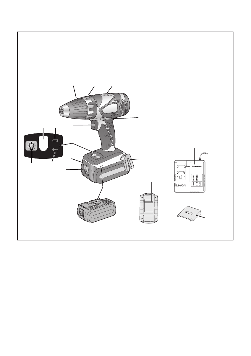
Keyless drill chuck
Mandrin porte-foret sans l
(A)
Mandril sin llave
Speed selector switch
Interrupteur de sélection de vitesse
(C)
Interruptor selector de velocidad
Belt hook
Crochet de ceinture
(E)
Gancho del cinturón
Battery pack release button
Bouton de libération de batterie autonome
(G)
Botón de liberación de batería
Control panel
Panneau de commande
(I)
Panel de controle
LED light on/off button
Bouton Marche/Arrêt de la lumière DEL
(K)
Botón ON/OFF de luz LED
Battery low warning lamp
Témoin d’avertissement de batterie basse
(M)
Luz de aviso de baja carga de batería
Battery charger
Chargeur de batterie
(O)
Cargador de batería
Clutch handle
Poignée de l’embrayage
(B)
Mango de embrague
Forward/Reverse lever
Levier d’inversion marche avant-marche arrière
(D)
Palanca de avance/inversión
Alignment marks
Marques d’alignement
(F)
Marcas de alineación
Battery pack
Batterie autonome
(H)
Batería
Overheat warning lamp (battery)
Témoin d’avertissement de surchauffe (batterie)
(J)
Luz de advertencia de sobrecalentamiento (batería)
LED light
Lumière DEL
(L)
Luz indicadora
Variable speed control trigger
Gâchette de commande de vitesse
(N)
Disparador del control de velocided variable
Pack cover
Couvercle de la batterie autonome
(P)
Cubierta de batería
- 3 -
Recommendations for use / Recommandations concernant l’utilisation / Recomendaciones par el uso
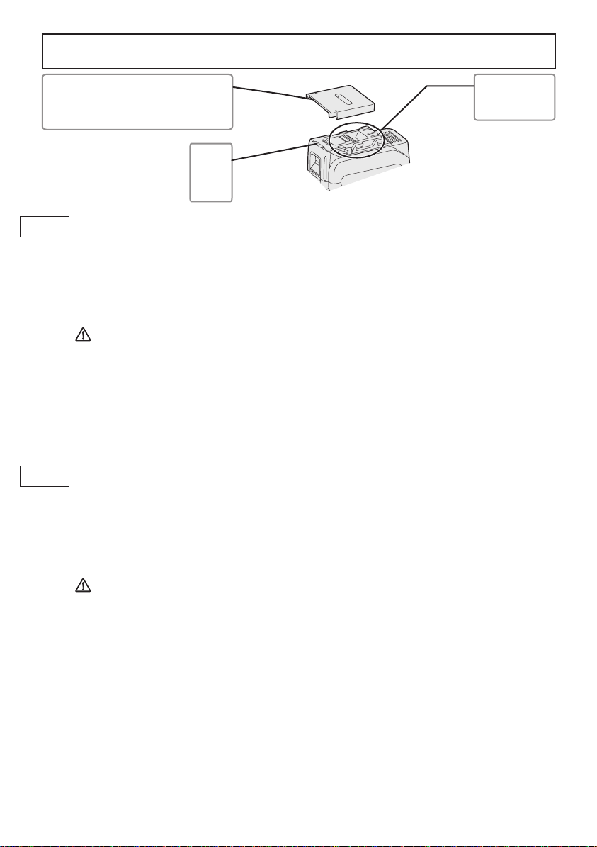
Be sure to use the Pack cover
GB
pour nous signaler que la machine ne fonctionne pas en toute sécurité même si un interrupteur a été enclenché.
Pack cover
Couvercle de la batterie autonome
Cubierta de batería
• When the battery pack is not being used, store the battery in a way that foreign substances such as dust and
water etc. do not contaminate the terminals. Be sure to attach the battery pack cover to protect the battery
terminals.
• When charging the battery pack, confirm that the terminals on the battery charger are free of foreign
substances such as dust and water etc. Clean the terminals before charging the battery pack if any foreign
substances are found on the terminals.
The life of the battery pack terminals may be affected by foreign substances such as dust and water etc.
during operation.
CAUTION: To protect the motor or battery, be sure to note the following when carrying out this operation.
• If the motor or battery becomes hot, the protection function will be activated and the motor or battery will stop
operating.
The overheat warning lamp on the control panel illuminates or flashes when this feature is active.
For safe use
• The battery pack is designed to be installed by proceeding two steps for safety. Make sure the battery pack is
installed properly to the main body before use.
• If the battery pack is not inserted firmly when the switch is switched on, the overheat warning lamp and the
battery low warning lamp will flash to indicate that safe operation is not possible, and the bit will not rotate
normally. Insert the battery pack into the body of the tool until the red label disappears.
Veillez à utiliser le couvercle de la batterie autonome
F
• Lorsque le couvercle de la batterie autonome n’est pas utilisé, rangez la batterie de façon à ce qu’aucun corps
étranger comme de la poussière et de l’eau ne contamine les bornes. Veillez à fixer le couvercle de la batterie
autonome afin de protéger les bornes de la batterie.
• Lors de la charge de la batterie autonome, assurez-vous que les bornes du chargeur de batterie sont libres de
tout corps étranger comme de la poussière et de l’eau, etc. Nettoyez les bornes avant de charger la batterie
autonome si des corps étrangers se trouvent sur les bornes.
La durée de vie des bornes de la batterie autonome peut être affectée par des corps étrangers comme de la
poussière et de l’eau, etc. pendant le fonctionnement.
MISE EN GARDE: Pour protéger le moteur ou la batterie, veillez à bien noter les points suivants lorsque
• Si le moteur ou la batterie deviennent chauds, la fonction de protection sera activée et le moteur ou la batterie
cesseront de fonctionner. Le témoin d'avertissement de surchauffe s'allume ou clignote sur le panneau de
commande lorsque cette caractéristique est active.
Pour un usage sans risque
• La batterie est conçue pour être installée en procédant en deux étapes pour des raisons de sécurité. Assurezvous que la batterie est mise en place correctement avant d'utiliser l'outil.
• Lorsque la batterie autonome n'est pas fermement insérée, le témoin d'avertissement de surchauffe et le témoin
d’avertissement de batterie basse clignotent et la machine ne fait pas tourner la mèche comme habituellement
Terminals
Bornes
Terminales
label
rouge
rojo
vous effectuez cette opération.
Insérez la batterie autonome dans le corps de l'outil jusqu'à ce que l'indicateur rouge disparaisse.
- 4 -

Asegúrese de utilizar la cubierta de la caja de batería
E
• Cuando no utilice la caja de batería, guarde la batería de tal forma que las materias extrañas tales como polvo
y agua, etc. ensucien los terminales. Asegúrese de colocar la cubierta de la caja de batería de tal forma de
proteger los terminales de la batería.
• Cuando cargue la caja de batería, confirme que los terminales en el cargador de batería estén libres de
materias extrañas tales como polvo y agua, etc. Limpie los terminales antes de cargar la caja de batería si hay
materias extrañas en los terminales.
La vida de los terminales de la caja de batería puede verse afectada por materias extrañas tales como polo y
agua, etc. durante su funcionamiento.
PRECAUCIÓN: Para proteger el motor o la batería, asegúrese de observar lo siguiente cuando efectúe
• Si el motor o la batería se calienta, se activará la función de protección y el motor o la batería dejará de
funcionar. La lámpara de advertencia de sobrecalentamiento en el panel de control se ilumina o destella
cuando esta característica está activada.
esta operación.
Para un uso más seguro
• La batería está diseñada para instalarse siguiendo dos pasos por motivos de seguridad.
Compruebe que la batería está instalada correctamente en el cuerpo principal antes de utilizar la herramienta.
• Si la batería no ha quedado bien introducida, la luz de advertencia de sobrecalentamiento y la luz de aviso de
baja carga de batería parpadearán, y la broca no girará del modo habitual para alertar al operario de que la
máquina no funcionará de manera segura si se acciona algún interruptor. Introduzca la batería en el cuerpo de
la herramienta hasta que el indicador rojo desaparezca.
- 5 -

This tool, as a complete unit with a battery pack,
satisfies appropriate IP Degrees of Protection
based on the IEC regulations.
Definition of IP code
IP5X: Ingress of dust is not totally prevented,
but dust shall not penetrate in a quantity to
interfere with satisfactory operation of the tool
or to impair safety (In case that the talcum
powder under 75 μm intrudes inside the tool).
IPX6: Water projected in powerful jets against
the tool from any direction shall have no
harmful effects (In case that, with a nozzle
of 12.5 mm inner diameter, approximately
100 L/min of normal temperature water is
injected to the tool for 3 minutes from 3 meter
distance).
LIMITED WARRANTY
The rating of IP56 qualifies this tool for the
minimum impact of water or dust, but not for
the assurance of performance in such conditions. See Safety and Operating Instructions
for further details for proper operation.
I. INTRODUCTION
These tools can be used to tighten
screws in clutch mode and to drill
holes in wood and metal in drill
mode. Additionally, model EY7940
can be used to drill holes in soft
concrete and similar materials in
hammer mode.
II. GENERAL SAFETY
RULES
WARNING! Read all instructions
Failure to follow all instructions listed
below may result in electric shock, fire
and/or serious injury. The term “power
tool” in all of the warnings listed below
refers to your main operated (corded)
power tool and battery operated
(cordless) power tool.
2) Do not op e rate power tools in
explosive atmospheres, such as in
the presence of ammable liquids,
gases or dust.
Power tools create sparks which may
ignite the dust or fumes.
3) Keep children and bystanders away
while operating a power tool.
Distractions can cause you to lose
control.
Electrical Safety
1) Power tool plugs must match the
outlet. Never modify the plug in any
way. Do not use any adapter plugs
wi th ear thed (grou nded) powe r
tools.
Unmodified pl u g s and matc h i n g
outlets will reduce risk of electric
shock.
2) Avoid body contact with earthed or
grounded surfaces such as pipes,
radiators, ranges and refrigerators.
There is an increased risk of electric
shock if your body is earthed or
grounded.
3) Do not expose power tools to rain
or wet conditions.
Water enterin g a power tool will
increase the risk of electric shock.
4) Do not abuse the cord. Never use
the cord for carrying, pulling or
unplugging the power tool. Keep
cord away from heat, oil, sharp
edges or moving parts.
Damaged or entangled cords increase
the risk of electric shock.
5) Whe n o p e ra t i ng a po w er tool
outdoors, use an extension cord
suitable for outdoor use.
Use of a cord suitable for outdoor use
reduces the risk of electric shock.
SAVE THESE INSTRUCTIONS
Work Area Safety
1) Keep work area clean and well lit.
Cl ut te r e d or da r k ar ea s in v i t e
accidents.
- 6 -

Personal Safety
1) Sta y aler t, watch what you are
doing and use common sense
when operating a power tool. Do
not use a power tool while you
are tired or under the influence of
drugs, alcohol or medication.
A moment of inattention while
operating power tools may result in
personal injury.
2) Use safety equipment. Always wear
eye protection.
Safety equipment such as dust
mask, non-skid safety shoes, hard
hat, or hearing protection used for
appropriate conditions will reduce
personal injuries.
3) Avoid accidental starting. Ensure
the switch is in the off position
before plugging in.
Carrying power tools with your finger
on the switch or plugging in the power
tools that have the switch on invites
accidents.
4) Rem o v e an y ad j u sti n g ke y or
wrench before turning the power
tool on.
A wrench or a key left attached to a
rotating part of the power tool may
result in personal injury.
5) Do not overreach. Keep prop er
footing and balance at all times.
This enables better control of the
power tool in unexpected situations.
6) Dress properly. Do not wear loose
clothing or jewelry. Keep your hair,
cl othing and gloves a way from
moving parts.
Loose clothes, jewelry or long hair can
be caught in moving parts.
7) If device s are provid ed for the
connection of dust extraction and
collection facilities, ensure these
are connected and properly used.
Use of these devices can reduce dust
related hazards.
Power Tool Use and Care
1) Do not force the power tool. Use
the correct power tool for your
application.
The correct power tool will do the job
better and safer at the rate for which it
was designed.
2) Do not use the power tool if the
switch does not turn it on and off.
Any power tool that cannot be
controlled with the switch is dangerous
and must be repaired.
3) Disconnect the plug from the power
source and/or the battery pack from
the power tool before making any
adjustments, changing accessories,
or storing power tools.
Such preventive safety measures
reduce the risk of starting the power
tool accidentally.
4) Store idle power tools out of the
reach of children and do not allow
persons unfamiliar with the power
tool or these instructions to operate
the power tool.
Power tools are dangerous in the
hands of untrained users.
5) Maintain power tools. Check for
misalignment or binding of moving
parts, breakage of parts and any
other condition that may affect the
power tools operation. If damaged,
have the power tool repaired before
use.
Many accidents are caused by poorly
maintained power tools.
6) Keep cutting tools sharp and clean.
Properly maintained cutting tools with
sharp cutting edges are less likely to
bind and are easier to control.
7) Use the power tool, accessories
and tool bits etc. in accordance
with these instructions and in the
manner intended for the particular
typ e of p ower t ool, t aking i nto
account the working conditions
and the work to be performed.
Use of the power tool for operations
different from those intended could
result in a hazardous situation.
- 7 -

Battery Tool Use and Care
1) Ensure t he switch is in the off
position before inserting battery
pack.
Inserting battery pack into power
tools that have the switch on invites
accidents.
2) Recharge only with the charger
specied by the manufacturer.
A charger that is suitable for one type
of battery pack may create a risk of
fire when used with another battery
pack.
3) U s e p o w er t o o ls o n l y w i t h
specific ally design ated batter y
packs.
Use of any other battery packs may
create a risk of injury and re.
4) When battery pack is not in use,
keep it away f r o m ot her metal
ob jects lik e pap er clips, coins,
keys, nails, screws, or other small
meta l objects that can make a
connection from one terminal to
another.
Shorting the battery terminals together
may cause burns, or a re.
5) Under abusive conditions, liquid
may be ejected from battery; avoid
co ntac t. If contact accidentally
occurs, flush with water. If liquid
contacts eyes, additionally seek
medical help.
Liquid ejected from the battery may
cause irritation or burns.
Service
1) Have your power tool serviced by a
qualified repair person using only
identical replacement parts.
This will ensure that the safety of
power tool is maintained.
III. SPECIFIC SAFETY
RULES
1) Wear ear protectors. Exposure to
noise can cause hearing loss.
2) Use auxiliary handles supplied with
the tool. Loss of control can cause
personal injury.
3) Hold po wer tools by i n s ulated
gripping surfaces when performing
an operation where the cutting tool
may contact hidden wiring.
Contact with a “live” wire will make
exposed metal parts of the tool “live”
and shock the operator.
4) Be aware that this tool is always in an
operating condition, since it does not
have to be plugged into an electrical
outlet.
5) I f t he bi t b ec om es ja mm ed ,
immediately turn the trigger switch
off to prevent an overload which can
damage the battery pack or motor.
Use reverse motion to loosen jammed
bits.
6) Do not operate the Forward/Reverse
lever when the trigger switch is on.
The battery will discharge rapidly and
damage to the unit may occur.
7) When storing or carrying the tool,
set the Forward/Reverse lever to the
center position (switch lock).
8) Do not strain the tool by holding the
speed control trigger halfway (speed
control mode) so that the motor stops.
The protection circuit will activate and
may prevent speed control operation.
If this happens, release the speed
control trigger and squeeze again for
normal operation.
9) Be careful not to get dust inside the
chuck.
10) Do not touch the rotating parts to
avoid injury.
11) Do not use the tool continuously for a
long period of time. Stop using the tool
from time to time to avoid temperature
rise and heat overload of the motor.
12) Do not drop the tool.
13) Wear dust mask, if the work causes
dust.
14) During charging, the charger may
become slightly warm. This is normal.
Do NOT charge the battery for a long
period.
- 8 -
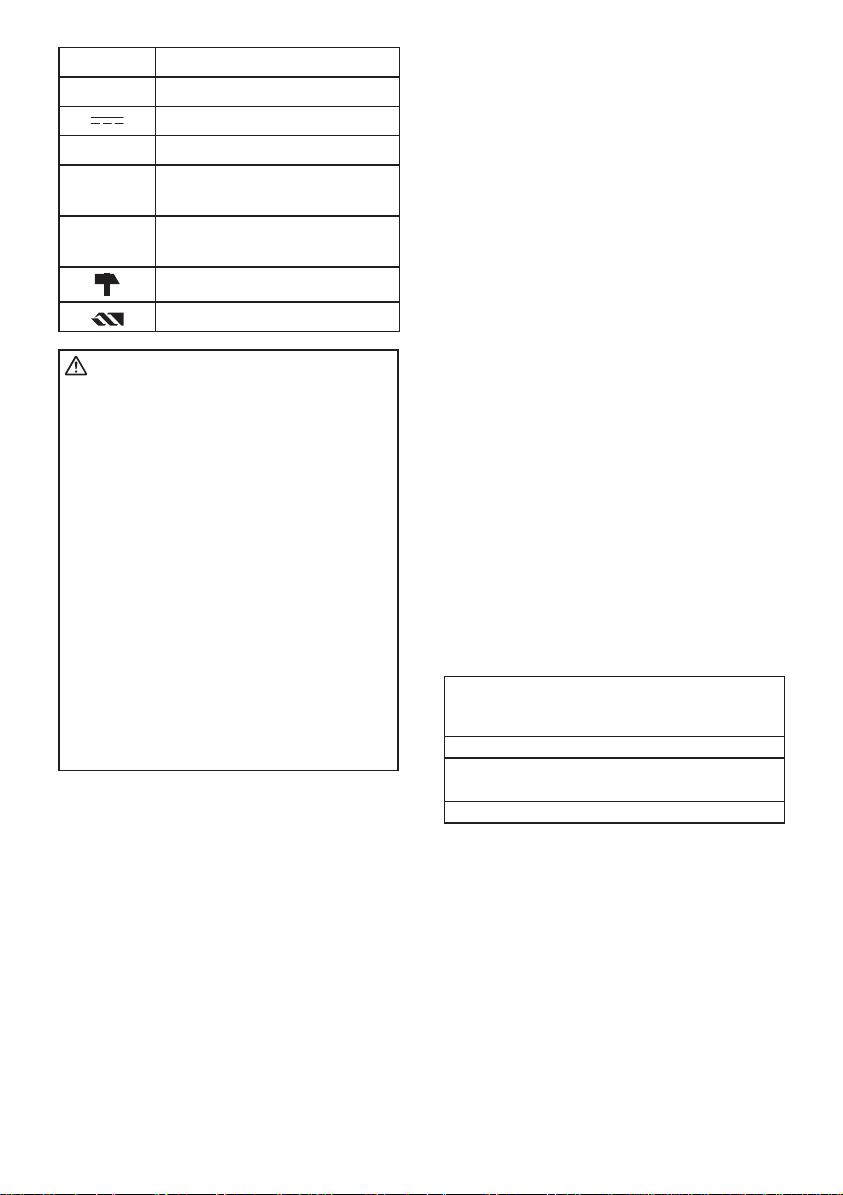
Symbol Meaning
V Volts
Direct current
n
o
-1
...min
Ah
WARNING:
Some dust created by power sanding,
sawing, grinding, drilling, and other
construction activities contains chemicals
known to the State of California to
cause cancer, birth defects or other
reproductive harm. Some examples of
these chemicals are:
* Lead from lead-based paints
* Crystalline silica from bricks and
cement and other masonry products
* Arsenic and chromium from chemically-
treated lumber.
To reduce your exposure to these
chemicals: work in a well ventilated
area, and work with approved safety
equipment, such as dust masks that
are specially designed to filter the
microscopic particles.
No load speed
Revolutions or
reciprocations per minutes
Electrical capacity of
battery pack
Rotation with hammering
Rotation only
IV. FOR BATTERY
CHARGER &
BATTERY PACK
Important Safety Instructions
1) SAVE THESE INSTRUCTIONS. This
manual contains important safety
and operating instructions for battery
charger.
2) Before using battery charger, read all
instructions and cautionary markings
on (1) battery charger, (2) battery
pack.
3) CAUTION - To reduce the risk of
injury, charge only Panasonic Battery
Pack as shown in last page.
Other types of batteries may burst
causing personal injury and damage.
4) Do not expose charger to rain or
snow.
5) To reduce the risk of damaging the
electric plug and cord, pull by plug
rather than cord when disconnecting
charger.
6) Make sure cord is located so that it
will not be stepped on, tripped over,
or otherwise subjected to damage or
stress.
7) An extension cord should not be used
unless absolutely necessary.
Use of improper extension cord could
result in a risk of fire and electric
shock. If extension cord must be used,
make sure:
a. that pins on plug of extension cord
are the same number, size and
shape as those of plug on charger.
b. that extension cord is properly wired
and in good electrical condition.
c. t hat wire size is large enou g h
for ampere rating of charger as
specied below.
RECOMMENDED MINIMUM AWG SIZE
OF EXTENSION CORDS FOR BATTERY
AC Input Rating. Amperes AWG Size of Cord
Equal to or
greater than
0 2 18 18 18 16
8) Do not operate charger with damaged
cord or plug replace them immediately.
9) Do not o p e r a t e charger if it has
received a sharp blow, been dropped,
or otherwise damaged in any way;
take it to a qualied serviceman.
10) Do not disassemble charger; take
it to a qualified serviceman when
service or repair is required. Incorrect
reassembly may result in a risk of
electric shock or re.
CHARGERS
But less
than
Length of Cord, Feet
25 50 100 150
- 9 -

11) To reduce the risk of electric shock,
unplug charger from outlet before
atte m ptin g any ma inte n a nce or
cleaning.
12) The charger and battery pack are
specically designed to work together.
Do not attempt to charge any other
cordless tool or battery pack with this
charger.
13) Do not attempt to charge the battery
pack with any other charger.
14) Do not attempt to disassemble the
battery pack housing.
15) Do not store the tool and battery pack
in locations where the temperature
may reach or exceed 50°C (122°F)
(such a metal tool shed, or a car
in the summer), which can lead to
deterioration of the storage battery.
16) Do not charge battery pack when the
temperature is BELOW 0°C (32°F)
or ABOVE 40°C (104°F). This is very
important.
17) Do not incinerate the battery pack. It
can explode in a re.
18) Avoid dangerous environment. Do not
use charger in damp or wet locations.
19) The charger is designed to operate on
standard household electrical power
only. Do not attempt to use it on any
other voltage!
20) Do not abuse cord. Never carry
c h a r g e r b y c ord or ya n k it t o
disconnect from outlet. Keep cord
away from heat, oil and sharp edges.
21) Charge the battery pack in a well
ventilated place, do not cover the
charger and battery pack with a cloth,
etc., while charging.
22) U s e of an a t t a c h m e n t no t
recommended may result in a risk
of fire, electric shock, or injury to
persons.
23) Do not short the batt ery pack. A
battery short can cause a large current
ow, over heating and burns.
24) NOT E : If the supply cord of this
appliance is damaged, it must only be
replaced by a repair shop appointed
by the manufacturer, because special
purpose tools are required.
25) T O R E D U C E T H E R I S K O F
E L E C T R I C S H O C K , T H I S
APPL I ANCE HAS A POLARIZE D
PLUG (ONE BLADE IS WIDER THAN
THE OTHER).
This plug will fit in a polarized outlet
only one way. If the plug does not fit
fully in the outlet, reverse the plug. If
it still does not fit, contact a qualified
electrician to install the proper outlet.
Do not change the plug in any way.
WARNING:
●
Do not use other than the Panasonic
battery packs that are designed for use
with this rechargeable tool.
●
Panasonic is not responsible for any
damage or accident caused by the use
of the recycled battery pack and the
counterfeit battery pack.
●
Do not dispose of the battery pack in a
re, or expose it to excessive heat.
●
Do not drive the likes of nails into the
ba tter y pack, s ubje ct it to shocks,
dismantle it, or attempt to modify it.
●
Do not allow metal objects to touch the
battery pack terminals.
●
Do not carry or store the battery pack
in the same container as nails or similar
metal objects.
●
Do not charge the battery pack in a
high-temperature location, such as next
to a re or in direct sunlight. Otherwise,
the battery may overheat, catch re, or
explode.
●
Never use other than the dedicated
charger to charge the battery pack.
Otherwise, the battery may leak,
overheat, or explode.
●
After removing the battery pack from
the tool or the charger, always reattach
the pack cover. Otherwise, the battery
contacts could be shorted, leading to a
risk of re.
●
W he n t h e B at t e r y P a c k H a s
Deteriorated, Replace It with a New
One. Continued use of a damaged
battery pack may result in heat
generation, ignition or battery rupture.
- 10 -
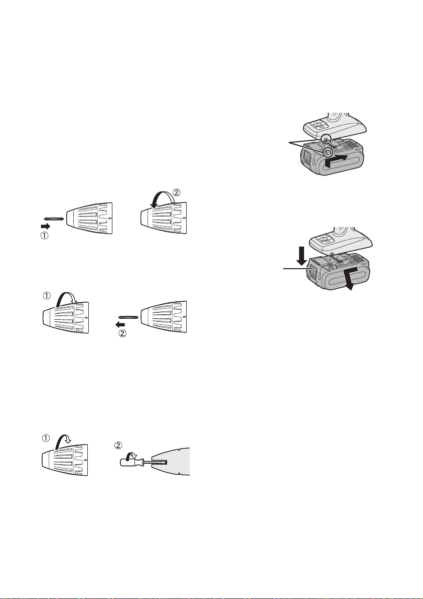
V. ASSEMBLY
Attaching or Removing Bit
NOTE:
Wh en a ttac hing or removing a bit,
disconnect battery pack from tool or
place the switch in the center position
(switch lock).
This tool is equipped with a keyless drill
chuck.
1. Attachment
Insert the bit and turn the lock collar
clockwise (looking from the front) to
tighten rmly until it stops clicking.
2. Removal
Turn the lock collar counterclockwise
(looking from the front), then remove
the bit.
Attaching or Removing Bat-
tery Pack
1. To connect the battery pack:
Line up the alignment marks and attach
the battery pack.
●
Slide the battery pack until it locks
into position.
Alignment marks
2. To remove the battery pack:
Pull the button from the front to release
the battery pack.
Button
NOTE:
If excessive play occurs in the chuck,
secure the drill in place and 1 open
the chuck jaws by turning the lock collar
and
tighten the screw (left-handed
2
screw) with a screwdriver by turning
it counterclockwise (viewed from the
front).
VI. OPERATION
[Main Body]
Switch Operation
1. The speed increases with the amount
of depression of the trigge r. When
beginning work, depress the trigger
slightly to start the rotation slowly.
2. A feedback electronic controller is used
to give a strong torque even in low
speed.
3. The brake operates when the trigger
is released and the motor stops
immediately.
NOTE:
When the brake operates, a braking
sound may be heard. This is normal.
- 11 -

CAUTION:
When operating the tool by pulling the
trigger, there may be a momentary lag
before rotation starts. This does not
signal a malfunction.
* This lag occurs as the tool’s circuitry
starts up when the trigger is pulled
for the first time after installing a new
battery pack or after the tool has not
been used for at least 1 minute (or at
least 5 minutes when the LED is on).
Rotation will start without any lag during
second and subsequent operations.
Switch and Forward/Reverse
Lever Operation
Forward Reverse
Switch lock
CAUTION:
To prevent damage, do not operate
Forward/Reverse lever until the bit
comes to a complete stop.
Reverse Rotation Switch
Operation
1. Push the lever for reverse rotation.
Check the direction of rotation before
use.
2. Depress the trigger switch slightly to
start the tool slowly.
3. After use, set the lever to its center
position (switch lock).
Clutch Torque Setting
Adjust the torque to one of the 18
clutch settings or “
EY74A1).
Adjust the torque to one of the 18 clutch
settings or “
NOTE:
Always make sure to stop operation
of the tool and disengage it from the
work, when you select Hammering
mode from Drilling mode or when
you shift to Drilling mode from
Hammering mode by rotating clutch
handle.
CAUTION:
Set the clutch setting at this mark ( )
before actual operation.
” position (EY7441,
”, “ ” position (EY7940).
Forward Rotation Switch
Operation
1. Push the lever for forward rotation.
2. Depress the trigger switch slightly to
start the tool slowly.
3. The speed increases with the amount
of depression of the trigger for efcient
tightening of screws and drilling.
The brake operates and the chuck
stops immediately when the trigger is
released.
4. After use, set the lever to its center
position (switch lock).
If the clutch handle cannot be set at
“drilling” or “hammering” mode after
driving with clutch function, set the
clutch handle at position 1 and operate
the clutch for a second.
Speed Selection
Choose a low or high speed to suit the
use.
LOW
The more the variable speed control
trigger is pulled, the higher the speed
becomes.
- 12 -
HIGH
CAUTION:
●
Che c k the spe e d select or switc h
before use.
●
Use at low speed when high torque is
needed during operation. (Using at high
speed when high torque is required
may cause a motor breakdown.)
●
Do not operate the speed selector
switch (LOW-HIGH) while pulling on
the speed control trigger. This can
cause the rechargeable battery to
wear quickly or damage the internal
mechanism of the motor.
* S e e spec i f i c ations fo r “MAX I M U M
RECOMMENDED CAPACITIES”.
CAUTION:
●
To prevent excessive temperature
increase of the tool surface, do not
operate the tool continuously using
two or more battery packs. The tool
needs cool-off time before switching
to another pack.
●
Do not close up vent holes on the
sides of the body during operation.
Otherwise, the machine function is
adversely affected to cause a failure.
●
Do NOT strain the tool (motor). This
may cause damage to the unit.
●
Use the t ool in such a w ay as t o
prevent the air from the body vent
holes from blowing directly onto your
skin. Otherwise, you may get burned.
How to Use the Belt Hook
WARNING!
●
Be sure to attach the belt hook
securelyto the main unit with the screw
firmly fastened. When the belt hook is
not rmly attached to the main unit, the
hook may disconnect and the main unit
may fall.
This may result in an accident or injury.
●
Periodically check screw for tightness.
If found to be loose, tighten rmly.
●
Be sure to attach the belt hook firmly
and securely onto a waist belt or other
belt. Pay attention that the unit does not
slip off the belt. This may result in an
accident or injury.
●
When the main unit is held by the belt
hook, avoid jumping or running with it.
Doing so may cause the hook to slip
and the main unit may fall.
This may result in an accident or injury.
●
When the belt hook is not used, be sure
to return it to the storing position. The
belt hook may catch on something.
This may result in an accident or injury.
●
When the unit is hooked onto the waist
belt by the belt hook, do not attach
driver bits to the unit. A sharp edge
object, such as a drill bit, may cause
injury or an accident.
Bit-locking Function
1. With the trigger switch not engaged
an d a s c re wd r iv e r bi t lo c k ed in
place, the tool can be used as a
manual screwdriver (up to 22.6 N·m,
230 kgf-cm, 199 in-lbs).
There will be a little play in the chuck,
but this is not a malfunction.
2. This feature is handy for tightening
screws that require more torque than
the maximum torque of the d r iver
(position
the tightness of a screw or to loosen an
extremely tight screw.
on the clutch), for conrming
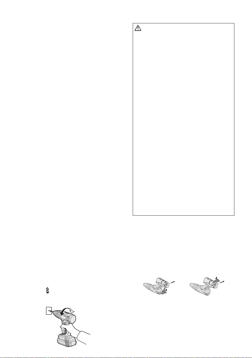
To Change the Belt Hook
Location Side
The belt hook can be attached to either
side of the unit.
1. Removing the hook
(1) Remove the nut.
(2) Draw out the hook.
1
2
2. Attaching the hook to the other side
(1) Insert the hook in the other side.
(2) Tighten the nut fully so that it
securely fastened.
- 13 -
1
2
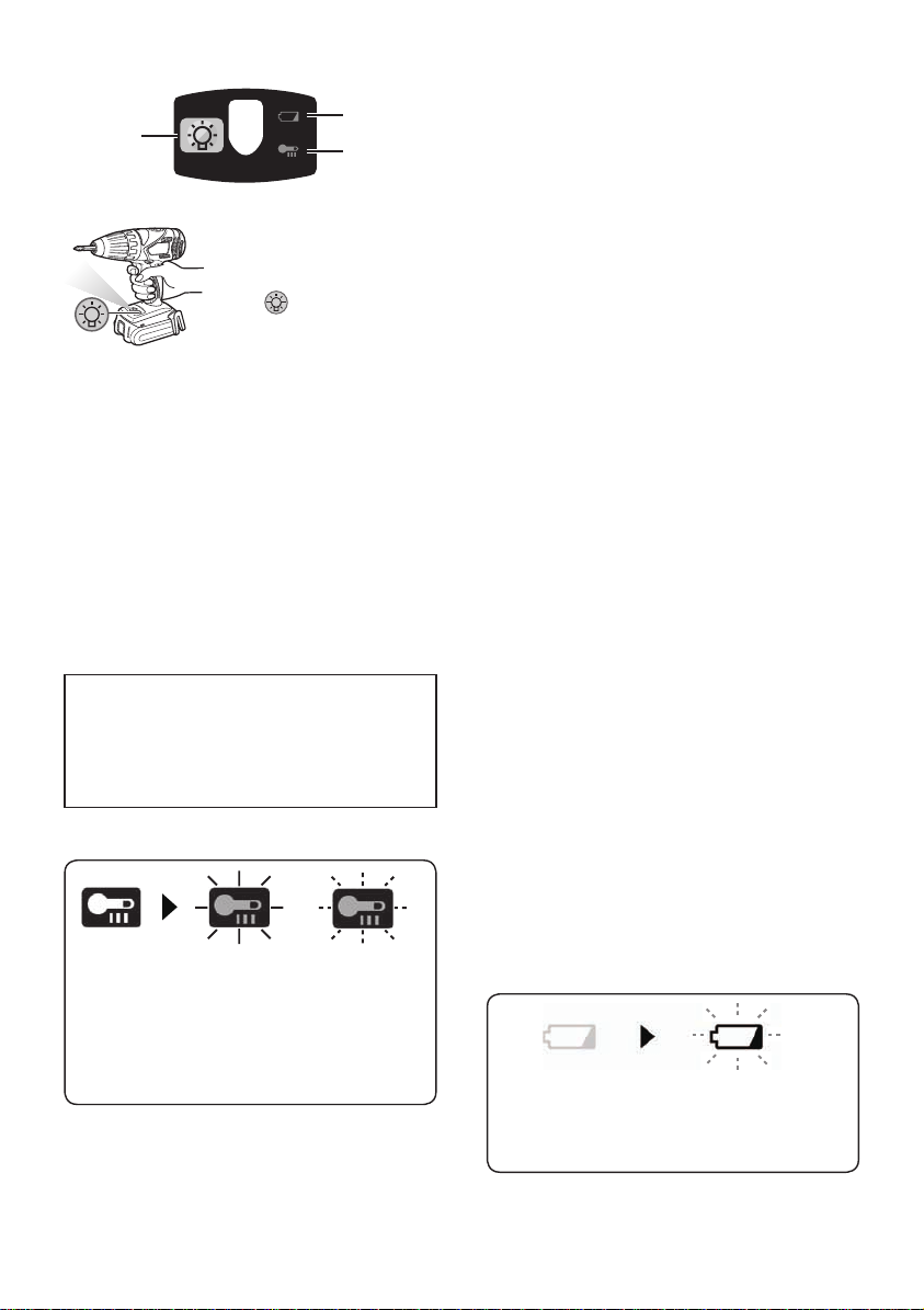
Control Panel
(1)
(1) LED light
Before the use of LED
lig h t, alwa y s pu ll the
power switch once.
Press
button.
The light illuminates with
very low current, and it does not adversely
affect the performance of the tool during
use or its battery capacity.
CAUTION:
●
The built-in LED light is designed
to illu minate the smal l work area
temporarily.
●
Do not use it as a substitute for a
regular flashlight, since it does not
have enough brightness.
●
LED light turns off when the tool has
not been used for 5 minutes.
Caution: DO NOT STARE INTO BEAM.
Use of cont r o l s or adjustments or
performance of procedures other than
those specified herein may result in
hazardous radiation exposure.
(2) Overheat warning lamp
(3)
(2)
the LED light
●
If the motor or battery becomes hot, the
protection function will be activated and
the motor or battery will stop operating.
The ov erheat warni n g lamp on the
control panel illuminates or ashes when
this feature is active.
●
If the overheating protection feature
ac ti va te s, all o w th e to o l t o coo l
thoroughly (at least 30 minutes). The
tool is ready for use when the overheat
warning lamp goes out.
●
Avoid using the tool in a way that causes
the overheating protection feature to
activate repeatedly.
●
If the tool is operated continuously under
high-load conditions or if it is used in hottemperature conditions (such as during
summer), the overheating protection
feature may activate frequently.
●
If the tool is used in cold-temperature
conditions (such as during winter) or if
it is frequently stopped during use, the
overheating protection feature may not
activate.
The performance of the EY9L42 deteriorates signicantly at and below 10°C
due to work conditions and other factors.
●
The ambient temperature range is
between 0°C (32°F) and 40°C (104°F).
If the battery pack is used when the
battery temperature is below 0°C (32°F),
the tool may fail to function properly.
●
When charging a cool battery pack (below
0°C (32°F)) in a warm place, leave the
battery pack at the place and wait for more
than one hour to warm up the battery to
the level of the ambient temperature.
Off
(normal
operation)
Illuminated:
Overheat
(motor)
Flashing:
Overheat
(battery)
Indicates operation has
been halted due to motor
or battery overheating.
To protect the motor or battery, be sure to
note the following when carrying out this
operation.
(3) Battery low warning lamp
Off
(normal
operation)
Exc essive (comp lete) discha rging of
lithium ion batteries shortens their service
Flashing
(No charge)
Battery protection
feature active
- 14 -

life dramatically. The driver includes a
battery protection feature designed to
prevent excessive discharging of the
battery pack.
●
The battery protection feature activates
immediately before the battery loses its
charge, causing the battery low warning
lamp to ash.
●
If you notice the battery low warning
lamp flashing, charge the battery pack
immediately.
●
If it is started with too little battery power
remaining, the tool may stop operating
without the battery low warning lamp
ashing rst. This indicates that there is
too little battery power remaining to use
the tool, and the battery pack should be
charged before further use.
●
If the tool is subject to a sudden load
during use that causes the motor to
lock up, the overdischarge prevention
sensor may be triggered, and the battery
low warning lamp may flash. The lamp
will stop flashing once you address the
cause of the motor’s locking up and cycle
the trigger.
●
The battery protection feature may
activate when a high load is abruptly
pl aced on the moto r, even if ample
battery charge remains. In this case, both
the battery low warning lamp and LED
light will ash (EY74A1).
●
If both the battery low warning lamp and
LED light flash, reduce the force with
which you are pushing on the driver or,
if using a drill driver, adjust the speed
switch to a lower setting (EY74A1).
Battery Pack Life
The rechargeable batteries have a
limited life. If the operation time becomes
extremely short after recharging, replace
the battery pack with a new one.
Battery Recycling
ATTENTION:
FOR Li ion Battery Pack
A Li-ion battery that is recyclable powers
the product you have purchased. Please
call 1-800-8-BATTERY for information
on how to recycle this battery.
[Battery Charger]
Charging
CAUTION:
●
If the temperature of the battery pack
falls approximately below −10°C (14°F),
chargi n g wi ll automatically stop to
prevent degradation of the battery.
●
The ambient temperature range is
between 0°C (32°F) and 40°C (104°F).
If the battery pack is used when the
battery temperature is below 0°C (32°F),
the tool may fail to function properly.
●
When charging a cool battery pack (below
0°C (32°F)) in a warm place, leave the
battery pack at the place and wait for more
than one hour to warm up the battery to
the level of the ambient temperature.
●
Cool down the charger when charging
more than two battery packs consecutively.
●
Do not insert your fingers into contact
hole, when holding charger or any other
occasions.
To prevent the risk of re or damage to the
battery charger.
●
Do not use power source from an engine
generator.
●
Do not cover vent holes on the charger
and the battery pack.
●
Unplug the charger when not in use.
NOTE:
Your battery pack is not fully charged at
the time of purchase. Be sure to charge
the battery before use.
- 15 -
 Loading...