

Panasonic DT2750MS User Manual

Operating
Instructions
HD/Multi-scan Color Monitor
Model No. DT-2750MS
Panasonic^
Read these instructions completely before operating this unit.

Dear Panasonic Customer:
This instruction booklet provides all the necessary operating information that you might require. We hope it will help
you to get the most performance out of your new product, and that you will be pleased with your Panasonic HD/Multiscan Color Monitor.
The serial number of your product may be found on its back. You should note it in the space provided below and retain
this booklet in case service is required.
Model number: DT-2750MS
Serial number:
Contents
Features.............................................................................................................2
IMPORTANT SAFETY NOTICE.........................................................................3
Precautions with regard to safety...................................................................4
Location and function of each part.................................................................7
Connections for RGB equipment (D-sub input)
Connections for RGB equipment (BNC input)
Connections for video equipment................................................................ 15
Connections for S-video equipment
.............................................................
Connections for component video equipment
Connections for external speakers...............................................................19
..........................................
.............................................
............................................
11
13
17
18
Before using the remote control unit............................................................20
Wireless remote control.................................................................................21
User control with the front buttons
1. Direct input signal selection...........................................................................................23
2. Picture and audio quality controls .................................................................................24
...............................................................
23
Memories.........................................................................................................32
RS-232C communication................................................................................33
Simplified wired communication...................................................................36
Power management ........................................................................................38
Signal discrimination flowchart.....................................................................38
Option ..............................................................................................................39
Timing charts for preset memory..................................................................39
Specifications..................................................................................................43

Features
1) Suitable for a wide range of applications;
• Component video, DTV, or DVD
• S-video, Composite video (NTSC, PAL, and SECAM)
• Data monitor supporting PC or Macintosh® VGA (640 x 480) up to UXGA (1600 x 1200) at
75 Hz flicker-free refresh
2) Super high quality CRT
• 0.6 fine stripe pitch (25% finer than most conventional CRTs)
• Superb display quality even in high resolution displays
• Glass with built-in microfilter for high contrast and brightness
3) Meet PC98 requirements
• DDC 1-2B for plug and play
• VESA DPMS Power management
4) Ergonomic and user-friendly design
• Temperature-controlled fan for minimal noise level
• Lowest power consumption through unique circuitry that allows for high voltage deflection
5) Compatible with most large or small systems configurations
• Convenient easy to use wireless remote control
• Bi-directional RS-232C communications enhance programmability
• Simplified wired communications supports stable parallel data transfer
• Monitor addressable function
6) Simple, user-friendly controls with on-screen display menu
7) Automatic input signal detector for quick setup
8) Powerful 5-watt front-firing stereo quality speakers for true multimedia applications
Note: • DTV: Digital Television
DVD: Digital Video Disc
• VESA DPMS is the requirement regarding the power consumption management from VESA.
VESA DPMS is an abbreviation of the following:—
VESA: Video Electronics Standard Association
DPMS: Dispiay Power Management Signaling
IMPORTANT SAFETY NOTICE
WARNING: To prevent damage which may result in fire or shock hazard, do not expose this appliance to
rain or moisture.
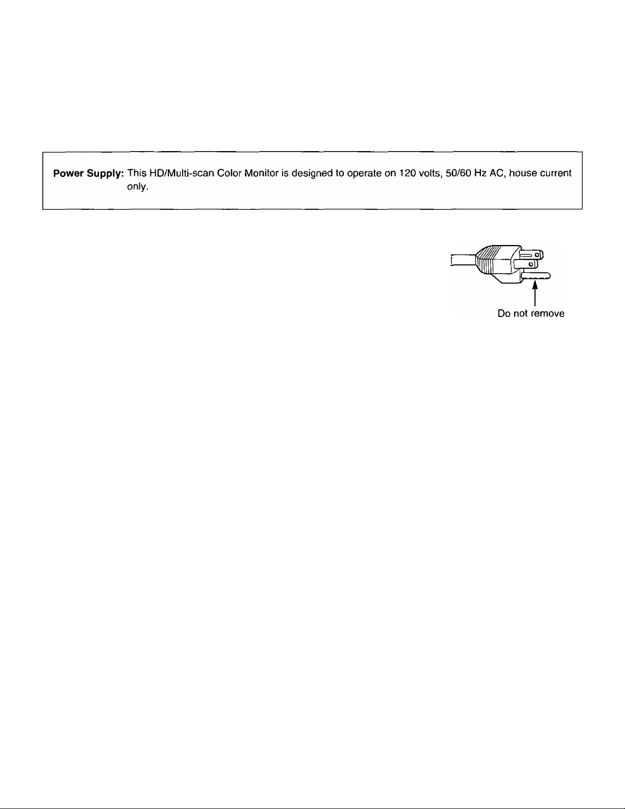
CAUTION: This equipment is equipped with a three-pin grounding-type power
plug. Do not remove the grounding pin on the power plug.
This plug will only fit a grounding-type power outlet. This is a safety
feature.
If you are unable to insert the plug into the outlet, contact an electrician.
Do not defeat the purpose of the grounding plug.
WARNING: This equipment has been tested and found to comply with the limits for a Class A digital device,
pursuant to Part 15 of the FCC Rules. These limits are designed to provide reasonable protection
against harmful interference when the equipment is operated in a commercial environment. This
equipment generates, uses, and can radiate radio frequency energy and, if not installed and used in
accordance with the instruction manual, may causes harmful interference to radio communications.
Operation of this equipment in a residential area is likely to cause harmful interference in which case
the user will be required to correct the interference at his own expense.
CAUTION: Any unauthorized changes or modifications to this equipment would void the users authority to
operate.

Precautions with regard to safety
WARNING
Setting up
Set up the monitor in a place which is strong enough to support it.
• If the setting-up location is not strong enough, the monitor may fall down or tip over, and damage or injury may
result.
Do not place anything on top of the monitor.
• If liquid gets spilled on the monitor or foreign objects get inside it, short-circuits can occur which may result in
fire.
If any foreign objects get inside the monitor, contact an Authorized Service Center.
Do not place the monitor on top of surfaces which are unstable.
• If the monitor is placed on top of a surface which is sloped or unstable, it may fall down or tip over, and injury or
damage could result.
Using the monitor
Do not remove the rear cover or cabinet or make any modifications yourself.
• High voltages which could cause fire or electric shocks are present inside this monitor.
Consult the place of purchase for any inspection, adjustment and servicing needs.
Do not insert any foreign objects into the monitor.
• Do not insert any metal objects or flammable objects into the monitor or drop them onto the monitor, as doing so
can result in fire or electric shocks.
Clean the power cable regularly to prevent it from becoming covered in dust.
• If dust builds up on the power cable plug, the resulting humidity can damage the insulation, which could result in
fire. Pull the power cable out from the wall outlet and wipe it with a dry cloth.
• If not using the monitor for an extended period of time, pull the power cable plug out from the wall outlet.
Do not damage the power cable or power cable plug.
• Do not damage, modify or bind the cable, place heavy objects on top of the cable, heat the cable or bring it
close to hot objects, twist or pull the cable strongly. If the cable is not handled properly, the live wires may
become exposed or a short-circuit may develop, and fire or electric shocks may result.
• If the power cable becomes damaged, contact an Authorized Service Center for repairs.
Do not pour liquid on the monitor or otherwise allow it to become wet.
• Fire and electric shocks may result.
Insert the power cable plug securely into the wall outlet.
• If the plug is not inserted correctly, overheating, fire or electric shocks could result.
If problems occur during use
If a problem occurs (such as no image or no sound) or if you notice smoke or a strange smell coming from the monitor, immediately turn off the power and disconnect the power cable from the wall outlet.
• A short-circuit could develop, and fire or electric shocks may result.
Contact an Authorized Service Center for repairs.
• Check that no more smoke is coming out, and then contact an Authorized Service Center for repairs
• Do not attempt to repair the monitor yourself, as this can be dangerous.
If foreign objects or liquids get inside the monitor, or if the monitor is dropped or the cover is broken, turn
off the power and disconnect the power cable from the wall outlet.

CAUTION
Setting-up
Do not set up the monitor in humid or dusty places or in places where the monitor may come into contact
with smoke or steam.
• To do so may result in fire or electric shocks.
Do not use a power supply which is outside the specified voltage range (120 V AC).
• To do so may result in fire or electric shocks.
Do not cover the ventilation holes.
• If the ventilation holes are covered, the inside of the monitor could overheat, and fire may result. Leave a space
of 10 cm or more between the monitor and the wall and maintain a distance of 10 cm or more between the
monitor and any audio/visual equipment when setting up the monitor.
• Do not place the monitor facing straight up or straight down, and do not tilt it on its side or place it upside down
or place it somewhere where there is poor ventilation.
• Do not place a tablecloth over the monitor, or place it on top of a rug or quilt.
When using the monitor
Do not place any heavy objects on top of the monitor.
• Doing so can cause the monitor to become unbalanced and fall, which could result in damage or injury.
Take steps to prevent the monitor from moving or turning after setting-up.
• If the monitor moves or tips over, injury may result.
• If placing the monitor on top of a table with casters, make sure that the casters are prevented from moving.
Do not sit on top of the monitor.
• Doing so may cause the monitor to tip over or break, and injury may result.
Always disconnect the power cable before moving the monitor.
• Moving the monitor with cables still attached can damage the cables, and fire or electric shocks may result.
• Always check that the power cable plug and cables are disconnected before moving the monitor.
• Two people are needed for unpacking and moving the monitor.
When disconnecting the power cable, hold the plug, not the cable.
• If the power cable itself is pulled, the cable will become damaged, and fire, short-circuits or serious electric
shocks may result.
Do not handle the power cable plug with wet hands.
• Doing so may result in electric shocks.
Observe the following when handling the batteries.
• Make sure the polarities 0 and 0 are correct.
• Use only the batteries specified.
• Do not heat or disassemble the batteries or place them into water or fire.
• Remove the batteries if not using the remote control unit for long periods.
• Do not place the batteries in a container together with metallic objects such as necklaces.
• If batteries are not treated properly, they may leak, and fire, electric shocks or contamination may result.
• If the batteries start leaking, contact an Authorized Service Center.
• If battery fluid gets onto your body, wash well with copious amounts of running water.

Cleaning
Ask an Authorized Service Center to clean inside the monitor at least once a year.
• If dust is left to build up inside the monitor without being cleaned out, fire may result. It is a good idea to clean
the inside of the monitor before the season for humid weather arrives. Please discuss with the Authorized
Service Center regarding cleaning costs.
Disconnect the power plug from the wall outlet as a safety precaution before carrying out any cleaning.
• Electric shocks may result if this is not done.
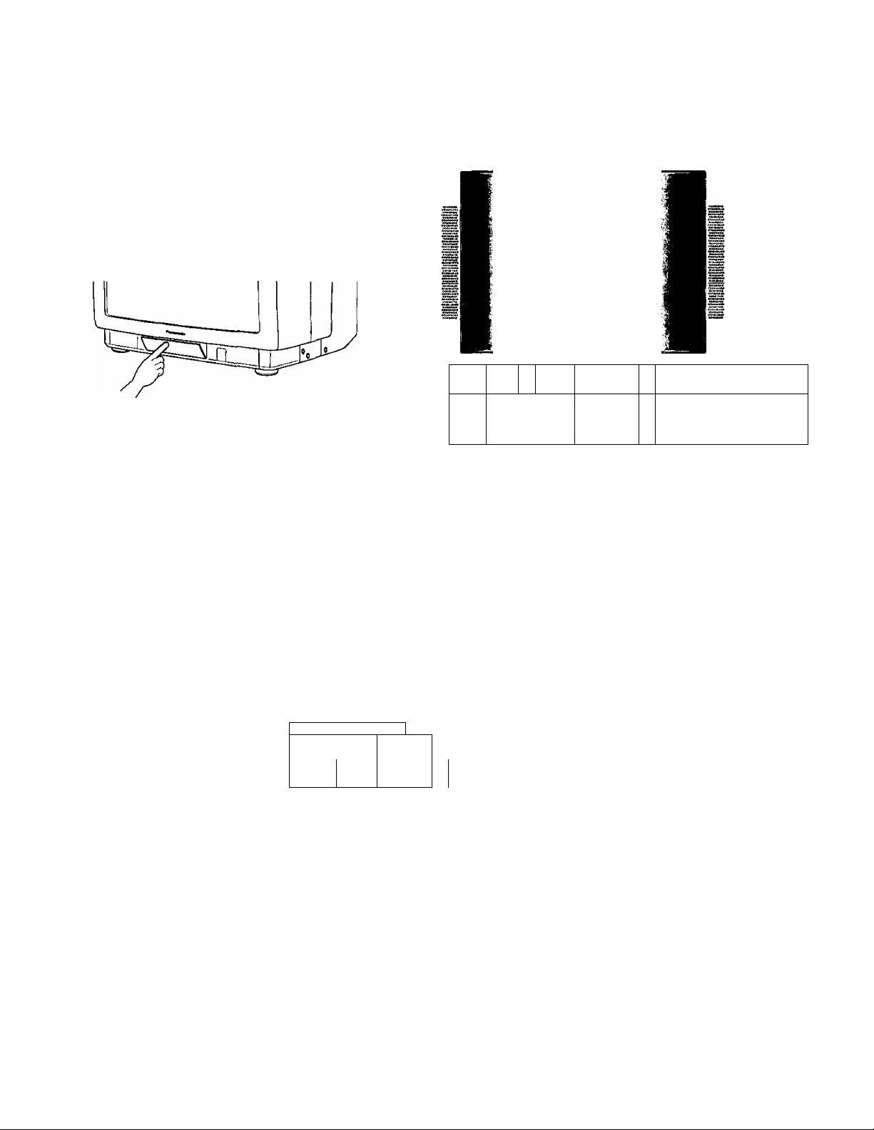
Location and function of each part
Monitor
<FRONT>
Opening the control panel cover or the connector panel cover.
1
r
—r
—g' '
Push the place marked “PUSH” and then
release it.
The cover will then open.
® Front connector panel
AV 2 INI
S-VIDEO VIDEO i AUDIO
S-video 2 Input connector-
f/o
Audio 2 Input RCA jacks
____________
L
p@i
®
©Front connector panel
RGB2 IN
R
©
iH
EZ}
-©Main power switch
©Power indicator
©Front control panel
15 Pin HDD-sub
Video 2 Input RCA jack
15 Pin HD D-sub:
This connector is for the 15 Pin HD D-sub end of
the signal cable for IBM or compatible
computers for mass production.
Video 2 Input RCA jack:
This jack is for composite video signal cable (not
supplied) when used with a video equipment.
S-video 2 Input connector:
This terminal is for S-video signal cable (not
supplied) when used with a video equipment
adopting S-video.
Audio 2 Input RCA jacks:
These jacks are audio inputs from a video
equipment (signal cable not supplied).
(D Main power switch
The main power switch is located on the lower right-side of the front bezel.
To turn on the monitor, push the main power switch so that the power indicator is lit green.
To turn off the monitor, push the main power switch again so that the power indicator is off.
By'pressing the POWER key on the remote control unit, the monitor is turned off and the power indicator is lit red,
however the monitor is not turned off completely. It is in stand-by mode, receptive to turn-on commands that may
be sent via remote control.
(3) Power indicator
The power indicator shows the monitor status (such as ON/OFF) normally.
Also, it indicates the power management status based on VESA DPMS as follows:—
Active
Stand-by
Suspend
Active off
r
@ Front control panel
This control panel can be used to make adjustments and input selections.
DTV/SET button
This button is used to
select DTV (Component
Video) input signal or to
set the control function or
the control level.*
H. Sync V. Sync
Yes
No
Yes
No
Yes
Yes
No
Green
Flashing (Interval 1 sec.)
No 1
Flashing (Interval 1 sec.)
Flashing (Interval 3 sec.)
Power indicator
RGB1 / — button
This button is used to select RGB1 input signal or to decrease
the control function or the control level.*
RGB2 / + button
This button is used to select RGB2 input signal or to
increase the control function or the control level.*
DTV
-O
I SET
* These buttons have a dual
function;—
SET, -, + function works when
the menu is visible on screen.
RGB1 RGB2 AVI AV2
^ ,rO O
AV2 button
This button is used to
select AV2 input signal.
AV1 button
This button is used to select
AVI input signal.
MENU
____
L
'MENU button
I
Control menu such as
brightness is separated to 2
groups. One is the picture
quality group (mainly
contrast). The other is the
geometric control group.
This button is used to select
the control menu group.
8
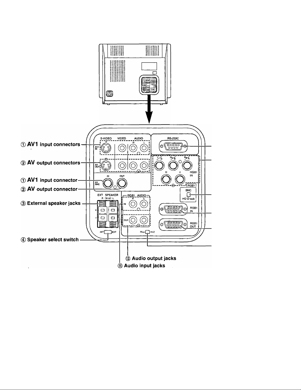
<REAR>
(1) RS-232C connector
(§) RGB1/Component video
BNC input connectors
®AV1 input connectors
These terminals are AVI input terminals.
S-video terminal is for S-video signal.
RCA jack named “VIDEO” is for composite video.
RCA jack named “R” is for audio R input.
RCA jack named “L” is for audio L input,
BNC jack named “AV1 IN” is for composite video.
Note: RCA jack named “VIDEO” is connected to
BNC jack named “AV1 IN” directly. Do not
input the composite signals both to RCA jack
named “VIDEO” and BNC jack named “AV
IN".
(7) BNC<=>HD D-sub switch
(D 15 Pin HD D-sub connector
forRGBI input
(9) 15 Pin HD D-sub connector
for RGB1 output
® 75 ohm«HI-Z selection
switch
AV output connectors
These terminals are AV output terminals.
S-video terminal is for S-video signal.
RCA jack named “VIDEO” is for composite video.
RCA jack named “R” is for audio R.
RCA jack named “L” is for audio L.
BNC jack named “AV OUT” is for composite video.
Note: RCA jack named “VIDEO” is connected to
BNC jack named “AV OUT’ directly. Do not
connect both connectors at the same time.

(D External speaker jacks
These jacks are for external speakers having an
impedance of 8 ohms.
To use the external speakers, place the speaker
select switch to the right position (EXT).
0 Speaker select switch
This switch is used to select either the internal
speakers or the external speakers.
To select the internal speakers, place the switch to
the left position marked “INT’.
To select the external speakers, place the switch to
the right position marked “EXT’.
CD RS-232C connector
This connector is used to control the monitor either
with RS-232C communication or the simplified wired
remote control.
(D RGB1/Component video BNC input connectors
These connectors are used for either RGB1 input
signals such as R, G, B, H and V from the computer
or the component video such as Y, Pb, and Pr from
the component video equipment like the digital TV
receiver and DVD player.
To use these connectors as RGB1 or component
video input, place the BNC»HD D-sub switch to the
upper position marked “BNC”.
® 75 ohmc^Hi-Z selection switch
This switch is used when more than 2 monitors are
connected at RGB1 input mode.
Normal position is to the left, marked “75 ohm”.
When you connect a second monitor using the
original cable, set this switch to “Hl-Z” and the
second monitor’s switch to the “75 ohm” position {to
the right marked “75 Q”).
Caution: When you connect only one monitor, do
not set this switch to the “Hl-Z” position.
Display image will be too bright.
0 Audio input jacks
These jacks are used for RGB1 audio inputs or
component video audio inputs.
® Audio output jacks
These jacks are used for RGB1 audio outputs or
component video audio outputs.
® BNCoHD D-sub switch
This switch is used to select the input signal of
RGB1 mode from the BNC connectors or HD D-sub
connector.
To select the signal from the BNC terminals, place
this switch to the upper marked “BNC”.
To select the signal from the HD D-sub connector,
place this switch to the lower position marked
“HD D-sub”.
® 15 Pin HD D-sub connector for RGB1 input
This connector is used for RGB1 input signals from
the computers.
(9) 15 Pin HD D-sub connector for RGB1 output
This connector is used for RGB1 output signals from
the monitor.
Note: 15 Pin HD D-sub connector for RGB1 output
is connected to the HD D-sub connector for
RGB1 input directly.
When two 15 Pin HD D-sub cables are
connected at the same time, place 75
ohm<=>HI-Z selection switch to the right
marked “Hl-Z”.
10

Connections for RGB equipment (D-sub input)
1. Turn off the power switches of the personal computer and/or your monitor if they are now on.
2. Connect the HD D-sub signal cable* to the personal computer and the monitor as shown in the following
figures {RGB1 input on the rear or RGB2 input on the front).
3. Connect the audio RCA signal cable {not supplied) to the personal computer if necessary.
4. If it has not been installed, first connect one end of the power cable to the monitor and then the other end to
the AC outlet**.
5- Turn on the power switches of the monitor and the persona! computer.
If the input is RGB1,
6. Set the BNC«HD D-sub switch to the “HD D-sub” position, and press RGB1 button on the front control panel
(see page 8).
7. This completes the single monitor installation using the HD D-sub connectors and supplied HD D-sub signal
cable.
The 75 ohmc^HI-Z selection switch should be set to the left, marked “75 i2”.
Caution: * Use only the supplied HD D-sub cable.
** If the AC outlet is of the two prong type, please consult with a licensed electrician.
To add a second monitor via bridge*connection
Check that you have set the BNC«HD D-sub switch to the “HD D-sub” position, and press RGB1 button on the
front control panel (see page 8).
8. Connect a signal cable from the RGB1 output connector of the first monitor to the RGB1 input connector of
the second monitor.
9. Set the 75 ohm<=>HI-Z selection switch of the first monitor to the right marked “Hl-Z”.
Also, set the 75 ohm^HI-Z selection switch of the second monitor to the left, marked “75 Q”.
10. This completes the extra monitor installation using the HD D-sub connectors and supplied HD D-sub signal
cable.
If the input is RGB2,
6. Press RGB2 button on the front control panel (see page 8).
7, This completes the single monitor installation using the HD D-sub connectors and supplied HD D-sub signal
cable.
11
Caution: * Do not connect a 15 Pin HD D-sub signal cable to the HD D-sub signal input marked “RGB 2”
for bridge-connection. Use only the terminals on rear panel marked “RGB 1”.
** If the AC outlet is of the two prong type, please consult with a licensed electrician.
Note: You can also connect MAC computer with MAC adaptor. (See page 39.)
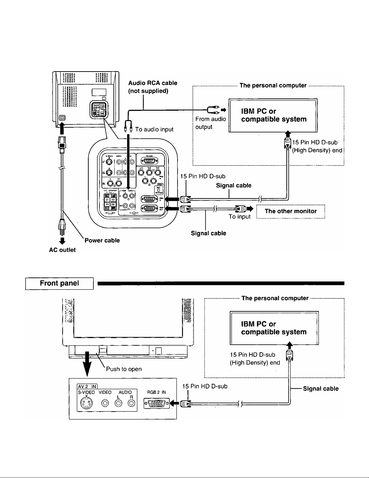
Rear panel
12

Connections for RGB equipment (BNC input)
7. Turn off the power switches of the video equipment and/or your monitor if they are now on.
2- Connect the BNC cables for RGB and the RCA cables for audio to the video equipment and the monitor as
shown in the following figures.
Note: These cables are not supplied with the monitor.
3. If it has not been installed, first connect one end of the power cable to the monitor and then the other end to
the AC outlet*.
4. Set the BNC»HD D-sub switch to the “BNC” position.
5. Turn on the power switches of the monitor and the RGB equipment.
6. Select “RGB1” by pressing front button RGB1 or pressing the RGB1 key on the remote control unit (see page
21).
Caution: *lf the AC outlet is of the two prong type, please consult with a licensed electrician.
13
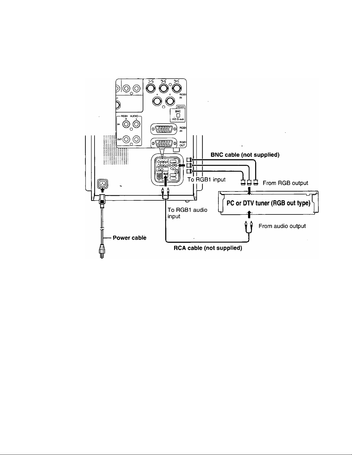
Rear panel
RGB1 IN connectors
4
AC outlet
14
 Loading...