

Panasonic CQ-VD6503N User Manual

Safety Information
CAUTION:
• PLEASE FOLLOW THE LAWS AND REGULATIONS
English
OF YOUR STATE, PROVINCE OR COUNTRY FOR
1
INSTALLATION OF THE UNIT.
• TO REDUCE THE RISK OF FIRE OR ELECTRIC
SHOCK OR PRODUCT DAMAGE, DO NOT EXPOSE
THIS APPLIANCE TO RAIN, SPLASHING, DRIPPING OR MOISTURE.
2
CQ-VD6503N
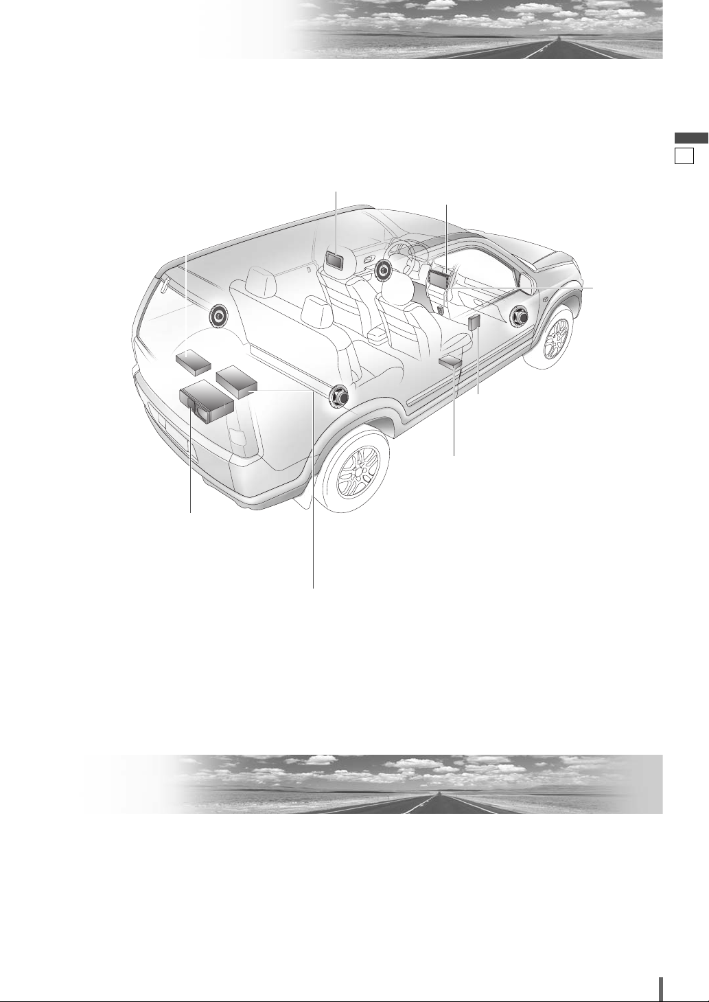
Upgrade Options
English
TV Tuner
(CY-TUP153N, option)
CD Changer
(CX-DP880N, option)
DVD Changer
(CX-DH801N, option)
Rear Monitor
Display Unit
CQ-VD6503N
Hands-Free Kit featuring
Bluetooth
(CY-BT100N, option)
Expansion Module
(CY-EM100N, option)
®
technology
iPod
2
®
Car Navigation System
(CN-DV2300N, option)
Contents
Safety Information................................................2
Upgrade Options ..................................................3
Contents................................................................3
Installation Guide .................................................4
Electrical Connections ........................................9
CQ-VD6503N
3
Installation Guide
Preparation Dashboard Installation
English
3
Caution
¡Please follow the laws and regulations of your
province or country for installation of the unit.
¡When bending the mounting tab of the mounting
collar with a screwdriver, be careful not to injure
your hands and fingers.
¡We strongly recommend you to wear gloves for
installation work to protect yourself from injuries.
¡Before installation, check the radio operation with
antenna and speakers.
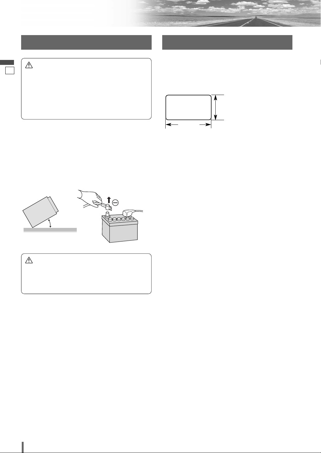
¡Disconnect the cable from the negative (–) battery ter-
minal (see caution below).
¡The unit should be installed in a horizontal position
with the front end up at a convenient angle, but not
more than 30°.
0 – 30°
Caution
¡Do not disconnect the battery terminals of a car with
trip or navigational computer since all user settings
stored in memory will be lost. Instead take extra
care with installing the unit to prevent shorts.
Installation Opening
The unit can be installed in any dashboard having an
opening as shown below. The dashboard should be 4.5
mm – 6 mm thick in order to be able to support the unit.
111.6 mm
182 mm
Installation Precautions
This product should be installed by a professional
installer, if possible.
In case of difficulty, please consult your nearest authorized Panasonic Service Centre.
1. This system is to be used only in a 12 V DC battery
system (car) with negative ground.
2. Follow the electrical connections carefully (a page 9-
19). Failure to do so may result in damage to the unit.
3. Connect the power lead after all other connections are
made.
4. Be sure to connect the battery lead (yellow) to the positive terminal (+) of the battery or fuse block (BAT) terminal.
5. Insulate all exposed wires to prevent short circuiting.
6. Secure all loose wires after installing the unit.
7. Please carefully read the operating and installation
instructions of the respective equipment before connecting it to this unit.
4
CQ-VD6503N

❏ Installation Hardware
(For Installation)
Trim Plate
q
Mounting Collar
w
Qty.DiagramItemNo.
1
<YFC054C088ZA>
1
<YFX214C437ZA>
❏ Transportation Bracket Removal
Be sure to remove the transportation brackets before
ø x 8
mm
use (installation). Use round head screws (
mm) for installation. (a page 7)
Be careful not to lose these screws.
Transportation Bracket
5
English
4
Lock Cancel Plate
e
Mounting Bolt (5 mmø)
r
Rear Support Strap
t
Round Head Screw
y
(5 mmø x 8 mm)
Flat-Head Screw
u
(5 mmø x 8 mm)
❏ Installation Hardware
Wiring)
(For
Power Connector
i
(ISO connector)
Reverse Extension Cord
o
2
<YFX994C134ZA>
1
<YEJVO1060>
1
<YEFG044C002>
2
6
<ZZBISVD6503>
Qty.DiagramItemNo.
1
1
Round Head Screw (5 mmø
x 8 mm)
❏ Before Installation
Caution
¡Do not press the panel forcefully.
¡Do not scratch the panel with fingernails or any hard
objects.
¡Do not bump the front panel.
a Failure to observe the above may damage or break
the glass on the surface of the touch panel.
Clip Connector
!0
<YEAJ012891>
ISO Antenna Adapter
!1
<YEAA33144>
Note:
¡The number in parenthesis underneath each accessory
part name is the part number for maintenance and
service.
¡Accessories and their parts numbers are subject to
modification without prior notice due to improvements.
¡Mounting Collar
shipment.
¡Use the supplied screws for installation exclusively. In
case of losing any of them, please order the specific
screw.
w is mounted on the main unit at
1
1
CQ-VD6503N
5
Installation Guide (continued)
Mounting and removing the Display Unit
English
❏ Mounting Procedures (A) (When using Mounting Collar w)
5
Note:
¡The car model, installation conditions and combination
of the units used may impose some restrictions on
opening and closing the monitor as well as on the
angle and position to which the monitor can be adjusted.
q
IMPORTANT
When this unit is installed in dashboard, ensure that there
is sufficient air flow around the unit to prevent damage
from overheating. Do not block any ventilation holes on
the unit.
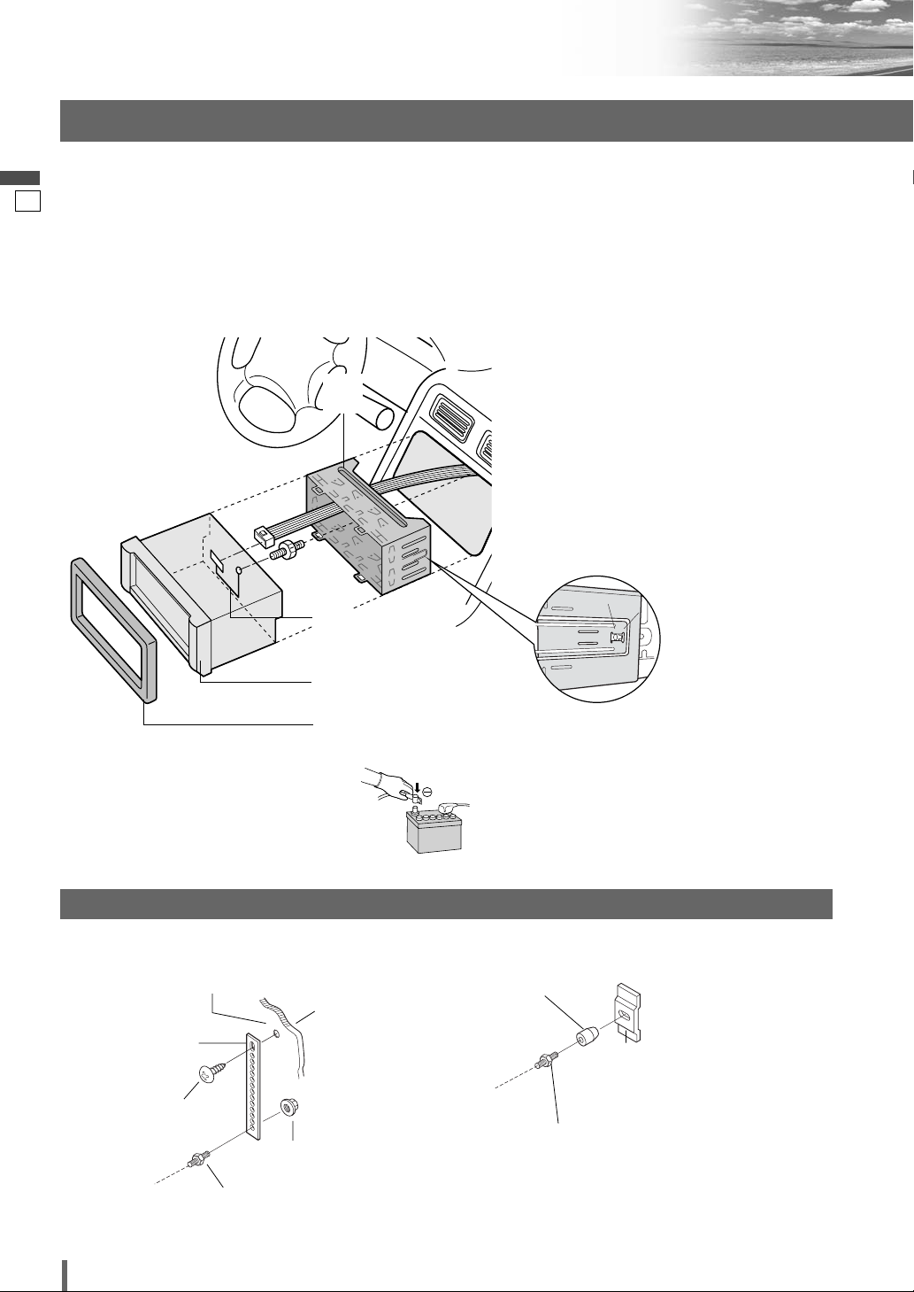
q
w
e
Insert the Mounting Collar w into the dashboard, and bend the mounting tabs out with
a screwdriver.
Establish the rear connection of the unit.
After fixing Power Connector
of the unit to the car body by either method
(a) or (b).
Insert the unit into Mounting Collar w.
Secure the clamp plate of Mounting Collar
to the hook.
i, fix the rear
w
w
e
r
t
Method for Fixing the Rear of the Unit
(a) Using the Rear Support Strap t.
Fire wall of car
3 mmø
Rear Support
t
Strap
Tapping Screw (option)
(5 mmø x 16 mm)
Hex. Nut (option)
(5 mmø)
To the unit
Mounting Bolt
r
(5 mmø)
Insert Trim Plate q.
r
After installation reconnect the negative (–)
t
battery terminal.
(b) Using the Rubber Cushion (option)
Rubber Bushing
(option)
Rear Support
Bracket
To the unit
r
(Provided on
the Car)
Mounting Bolt
(5 mmø)
Snapping point
6
CQ-VD6503N
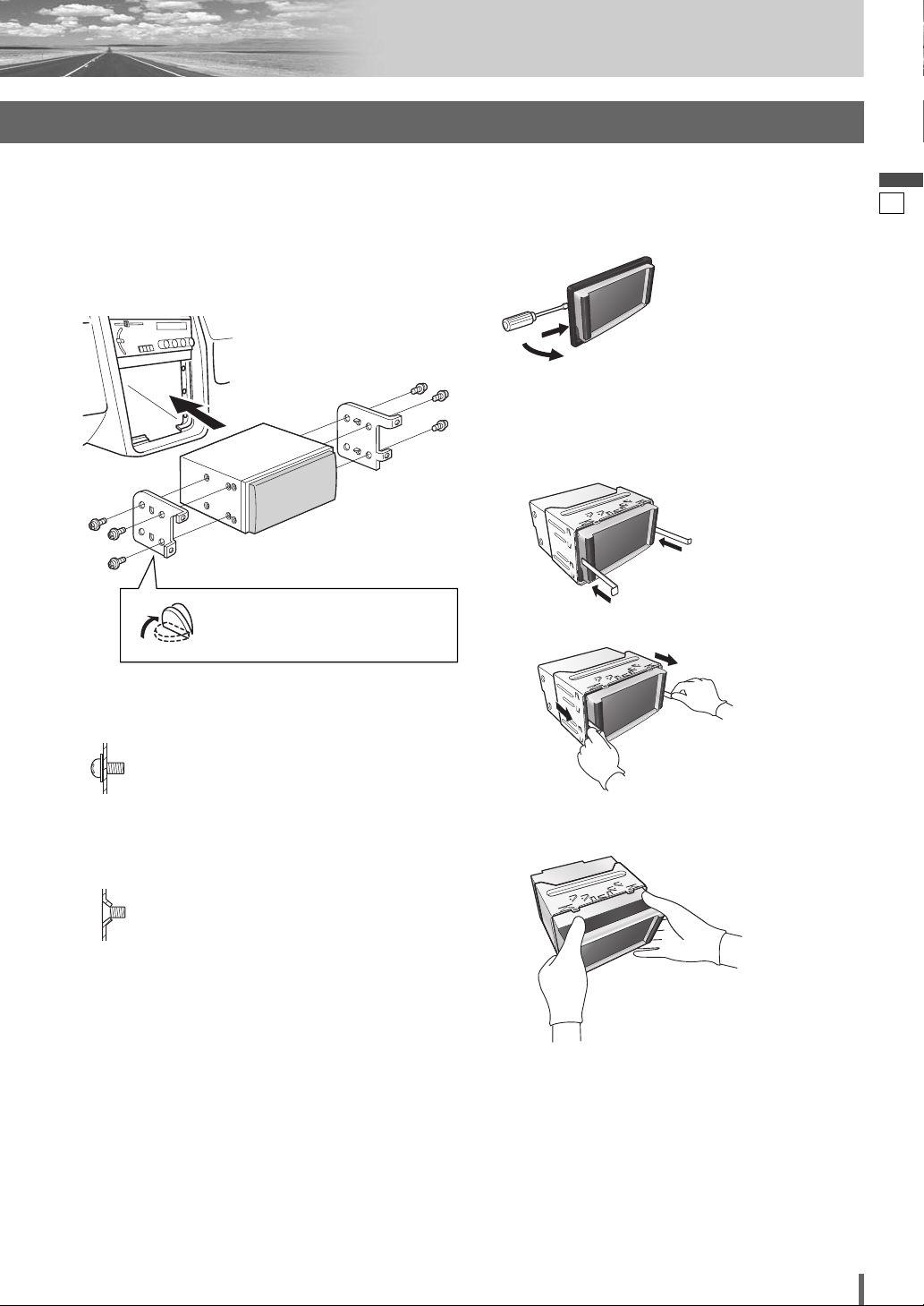
❏ Mounting Procedures (B)
(When not using Mounting Collar w)
Use the brackets supplied with your car when mounting
this unit. The bracket shape and mounting method vary
with car manufacturers, car types and manufacturing
year. Please consult your nearest dealer or installer.
English
❏ Removing Procedures
6
q Remove the trim plate q.
q
w
w Lock release.
q Insert the lock cancel plate e until you hear a
click.
Note: Use pliers to bend the
fingers on the bracket vertically.
Select mounting screws according to the hole positions
and hole shape of the bracket.
y Round Head Screw
(5 mmø x 8 mm)
Note:
Recycle the Round Head Screws that fixed the
transportation brackets for two more
positions. (a page 5)
u Flat-Head Screw
(5 mmø x 8 mm)
w Pull the unit out.
e Pull the unit out with both hands.
CQ-VD6503N
7
 Loading...