

Page 1
This product is eligible for the P2HD
5 Year Warranty Repair Program. For
details, see page 4.
Before useDescription of
Operating Instructions
Memory Card Camera-Recorder
Model No. AG-HPX172EN
parts
PreparationShootingPlaybackEditingDisplaysMenuReference
Before operating this product, please read the instructions carefully and save this
manual for future use.
F0808T0 -P
Printed in Japan
D
ENGLISH
VQT1U95
Page 2
Read this rst!
DO NOT REMOVE PANEL COVERS
g
BY UNSCREWING THEM.
To reduce the risk of electric shock, do not
remove cover. No user serviceable parts inside.
Refer servicing to qualied service personnel.
WARNING:
•
TO REDUCE THE RISK OF FIRE OR SHOCK
HAZARD, DO NOT EXPOSE THIS EQUIPMENT
TO RAIN OR MOISTURE.
•
TO REDUCE THE RISK OF FIRE OR SHOCK
HAZARD, KEEP THIS EQUIPMENT AWAY
FROM ALL LIQUIDS. USE AND STORE ONLY
IN LOCATIONS WHICH ARE NOT EXPOSED
TO THE RISK OF DRIPPING OR SPLASHING
LIQUIDS, AND DO NOT PLACE ANY LIQUID
CONTAINERS ON TOP OF THE EQUIPMENT.
WARNING:
Always keep memory cards or accessories
(coin battery, microphone holder screws,
microphone holder adapter, ferrite cores,
INPUT terminal cover) out of the reach of
babies and small children.
CAUTION:
TO REDUCE THE RISK OF FIRE OR SHOCK
HAZARD AND ANNOYING INTERFERENCE, USE
THE RECOMMENDED ACCESSORIES ONLY.
CAUTION:
In order to maintain adequate ventilation, do
not install or place this unit in a bookcase,
built-in cabinet or any other conned space. To
prevent risk of electric shock or re hazard due
to overheating, ensure that curtains and any
other materials do not obstruct the ventilation.
indicates safety information.
Camera-Recorder
The rating plate is on the underside of the
viewnder.
AC Adapter
The rating plate is on the underside of the AC
Adapter.
Disconnect the AC mains plug from the AC
mains socket when not in use.
CAUTION:
THE MAINS PLUG OF THE POWER SUPPLY
CORD SHALL REMAIN READILY OPERABLE.
THE AC RECEPTACLE (MAINS SOCKET
OUTLET) SHALL BE INSTALLED NEAR
THE EQUIPMENT AND SHALL BE EASILY
ACCESSIBLE.
TO COMPLETELY DISCONNECT THIS
EQUIPMENT FROM THE AC MAINS,
DISCONNECT THE POWER CORD PLUG
FROM THE AC RECEPTACLE.
CAUTION:
Do not jar, swing, or shake the unit by its
handle while the conversion lens or another
accessory is attached.
Due to the added weight of the conversion
lens, any strong jolt to the handle may damage
the unit or result in personal injury.
CAUTION:
EXCESSIVE SOUND PRESSURE FROM
EARPHONES AND HEADPHONES CAN
CAUSE HEARING LOSS.
CAUTION:
Do not lift the unit by its handle while the tripod
is attached. When the tripod is attached, its
weight will also affect the unit’s handle, possibly
causing the handle to break and hurting
the user. To carry the unit while the tripod is
attached, take hold of the tripod..
CAUTION:
Danger of explosion or re if battery is mistreated.
For Battery Pack
• Replace only with same or specied type.
• Do not disassemble or dispose of in re.
• Do not store in temperatures over 60°C.
• Do not leave the battery in an automobile
exposed to direct sunlight for a long period of
time with doors and windows closed.
• Use specied charger.
For Battery of Remote Controller
• Replace battery with part No. CR2025 only.
• Do not recharge the battery.
• Do not disassemble or dispose of in re.
• Do not store in temperatures over 60°C.
2
CAUTION:
Do not leave the unit in direct contact with the
skin for long periods of time when in use.
Low temperature burn injuries may be suffered
if the high temperature parts of this unit are
in direct contact with the skin for long periods
of time.
When using the equipment for long periods of
time, make use of the tripod.
Page 3

Recommendation for Use of Genuine Panasonic Battery Pack (Rechargeable Battery)
Thank you for using a Panasonic product.
It has been our policy to recommend that the genuine Panasonic battery pack be used for any
Panasonic product that uses a battery pack, including digital cameras. It has, however, been found that
imitation battery packs that look very similar to the genuine Panasonic battery pack are marketed in
some markets.
Some of these imitation battery packs are not equipped with any protective devices that meet given
quality standards for permitting use at high power outputs and for long hours.
If any of these battery packs of inferior quality is used, it could lead to an accident or failure
involving ring or explosion.
To ensure that our products are used in utmost safety, we once again remind you that we recommend
the use of a genuine Panasonic battery pack for any Panasonic product that is to use a battery pack.
The genuine Panasonic battery packs are sold under our stringent quality control.
Please be advised that we are not liable for any accident or failure occurring as a result of use of an
imitation battery pack.
We appreciate your kind understanding and cooperation in this regard.
Operating precaution
Operation near any appliance which generates strong magnetic elds may give rise to noise in the video
and audio signals. If this should be the case, deal with the situation by, for instance, moving the source of
the magnetic elds away from the unit before operation.
IMPORTANT
“Unauthorized recording of copyrighted television programs, video tapes and other materials may infringe
the right of copyright owners and be contrary to copyright laws.”
3
Page 4
4
Software information for this product
1. Customer advisory: This product includes software licensed under the GNU General Public License
(GPL) and GNU Lesser General Public License (LGPL); customers have the right to download, modify,
and redistribute source code for this software.
Descriptions of the GPL and LGPL are stored on the installation CD included with this camera-recorder.
See the folder named \LDOC. (The description is the original (written in English).) To download the
relevant source code, visit https://eww.pavc.panasonic.co.jp/pro-av/
Please note that we cannot answer any questions you may have about the content, etc. of any source
code you may obtain from the above Web site.
2. This product includes software licensed under the MIT License. A description of the MIT is stored on
the installation CD included with this camera-recorder. See the folder named \LDOC. (The description is
the original (written in English).)
• LEICA is a trademark of Leica Microsystems IRGmbH.
• DICOMAR is a trademark of Leica Camera AG.
• SD logo is a trademark.
All other explanations, company names, and product names are the registered trademarks of the
respective companies.
Thank you for purchasing this Panasonic P2HD device.
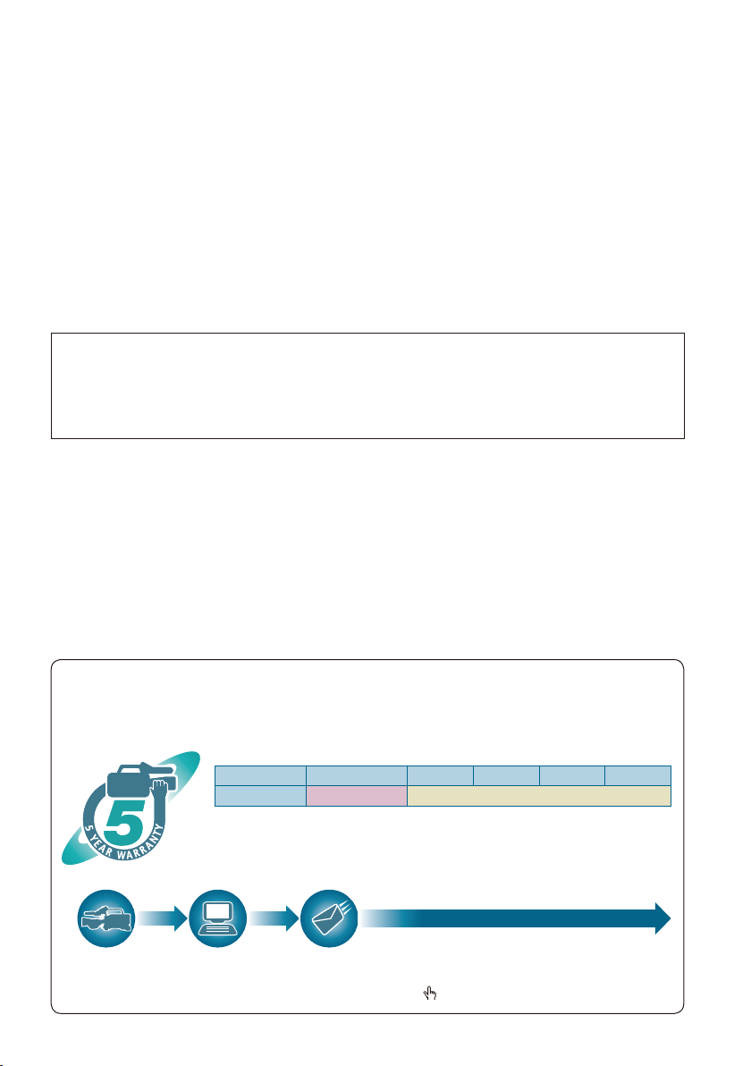
P2HD 5 Year Warranty Repair Program
Register as a user for this device to receive a special service warranty up to ve years of free warranty
repairs.
Customers who register as users on the website will receive a extended warranty repair
valid for up to ve years.
1st year 2nd year 3rd year 4th year 5th year
P2HD device*2Basic warranty
*1: Please note that this extended warranty is not available in some countries/regions see web
site below for details. *2: Not all models eligible for extended warranty coverage. *3: The basic
warranty period may vary depending on the country/region see enclosed warranty for warranty
coverage. *4: Not all repair work is covered by this extended warranty see enclosed warranty
card for warranty coverage. *5: The maximum warranty period may be adjusted depending on
the number of hours the device has been used.
*3
*1
Extended warranty repair
Free 5 years of Warranty Repairs
Purchase
P2 product
Details about user registration and the extended warranty:
Register online
within 1 month
“Registration Notice”
e-mail sent
Make sure to save the “Registration Notice”
e-mail during the warranty period.
http://panasonic.biz/sav/pass_e
*5
*4
Page 5

Contents
Read this rst! ..................................................... 2
Recommendation for Use of Genuine
Panasonic Battery Pack
(Rechargeable Battery) ................................... 3
Software information for this product ............... 4
Before use
Outline of operations .......................................... 7
Precaution for use ............................................... 8
Accessories ......................................................... 9
Optional units ...................................................... 9
About this manual ............................................... 9
Description of parts
Description of parts .......................................... 10
Right side and rear side .................................. 10
Left side ........................................................... 11
Terminals and mounting parts ......................... 12
Remote control ................................................ 13
Preparation
The battery ......................................................... 14
Charging .......................................................... 14
Installing and removing the power supply ...... 15
Installing and removing the battery ................. 15
Connecting and disconnecting
the power cord ............................................. 15
Adjusting the hand strap .................................. 16
Attaching the shoulder strap ............................ 16
Detaching and attaching the lens hood .......... 16
The remote control ............................................ 17
Insert the battery ............................................. 17
Remote control setup ...................................... 17
Turn on/off the camera ...................................... 18
Tally lamp ........................................................... 18
Viewnder .......................................................... 19
Using the viewnder ........................................ 19
Using the LCD ................................................. 20
Emphasizing outlines ...................................... 20
Adjusting the screen display ............................ 21
Adjusting the backlight ..................................... 22
Flipping images vertically and horizontally ...... 22
Switching between overscan and
underscan .................................................... 22
Setting the calendar .......................................... 23
Shooting
Basic shooting operations ............................... 24
Preparing to shoot ........................................... 24
Shooting in auto mode .................................... 24
Checking photos taken (REC CHECK) ........... 25
P2 card access lamps ..................................... 25
Protecting against a possible erasure ............. 25
Formatting P2 cards ........................................ 25
Recording times .............................................. 26
Remove the P2 card ........................................ 27
Using SD/SDHC memory cards ........................ 28
Installing and removing
the SD memory card ................................... 28
Formatting SD memory card ........................... 28
Cautions in using SD memory cards ............... 28
Using the zoom function ................................... 29
Digital zoom function ....................................... 29
Variable frame rates (VFR) ................................ 30
Native recording .............................................. 31
Standard recording .......................................... 31
Using variable frame rates (VFR) .................... 32
Shooting in 1080i/576i progressive mode ....... 33
Shooting in manual mode ................................. 34
Switching to manual mode .............................. 34
Manual focusing .............................................. 34
Using focus assist ............................................ 35
Iris adjustments ............................................... 35
Adjusting the gain ............................................ 36
Light intensity adjustments .............................. 36
Adjusting the white balance ............................. 37
Black balance adjustments .............................. 38
Auto Tracking White (ATW) .............................. 38
Shooting techniques for different targets ....... 39
Low-angle shooting ......................................... 39
Self-portrait shooting ....................................... 39
Zebra pattern ................................................... 39
Marker ............................................................. 39
Checking and displaying shooting status ........ 40
Changing the image size ................................. 40
Optical Image Stabilizer................................... 41
Adding effects to images ................................. 41
Using the USER buttons .................................. 41
Backlight compensation ................................... 41
Color bars ........................................................ 41
Waveform monitor function .............................. 42
Adjusting the volume while shooting ............... 42
Backup recording ............................................. 42
2-slot continuous recording ............................. 43
Shot mark function .......................................... 43
Text memo recording ....................................... 43
Time stamp function ........................................ 43
LAST CLIP DELETE function .......................... 44
Using the special recording functions ............ 45
Pre-recording (PRE REC) ............................... 45
Interval recording (INTERVAL REC) ................ 45
One-shot recording (ONE-SHOT REC) ........... 46
Loop recording (LOOP REC) .......................... 46
Adjusting the shutter speed ............................. 48
Synchro scan ................................................... 49
5
Page 6

6
Switching Audio Input ....................................... 50
Using the built-in microphone .......................... 50
Using another microphone and
audio equipment .......................................... 50
Adjusting the recording level ........................... 51
Using scene les ............................................... 52
Changing scene le settings ........................... 52
Saving scene les and other settings on
SD memory cards .......................................... 54
Clip metadata ..................................................... 56
Using the Counter ............................................. 57
Counter display ................................................ 57
1394TC preset mode ....................................... 57
Charging the built-in battery/
Setting the time data ..................................... 58
Recharging the built-in battery ........................ 58
Setting the time code ....................................... 58
Specifying the time code (TC PRESET) .......... 58
Setting user information................................... 60
Playback
Basic playback operations ............................... 62
Thumbnail screen .............................................. 63
Basic thumbnail screen operations.................. 63
Adding shot marks to clips .............................. 65
Clearing the thumbnail screen ......................... 65
Direct shooting functions ................................. 65
Thumbnail operations ....................................... 66
Selecting the thumbnail display method
(THUMBNAIL) ............................................. 66
Deleting clips and formatting cards
(OPERATION) ............................................. 67
Checking the clip or card information
(PROPERTY) .............................................. 68
Editing the recorded clip metadata .................. 70
Uploading the metadata (META DATA) ............ 71
Useful playback functions ................................ 73
Variable speed search ..................................... 73
Slow playback .................................................. 73
Fast forward/rewind playback .......................... 73
Frame-by-frame playback ................................ 73
Clip skip ........................................................... 74
Adjusting the volume ....................................... 74
Viewing images on a monitor .......................... 74
Checking the date and time ............................. 74
Editing
Connecting external units ................................ 75
Headphones .................................................... 75
External microphone ....................................... 75
Computer (non-linear editing/le transfer) ....... 76
Hard disk drive (data copying) ......................... 77
Digital video equipment (Dubbing) .................. 78
Video deck (Dubbing) ...................................... 79
TV/Monitor (playback/dubbing) ........................ 79
Nonlinear editing with P2 card (PC mode) ...... 80
Copying from P2 cards to
the hard disk drive (1394 HOST mode) ........ 82
Warnings ......................................................... 84
Dubbing .............................................................. 85
Digital input/output ........................................... 85
Analog output .................................................. 85
Displays
Screen displays ................................................. 86
Regular displays .............................................. 86
Warnings ......................................................... 90
Setting the DISPLAY items .............................. 92
Menu
Using the setup menus ..................................... 93
Using the menus.............................................. 93
Initializing the menu settings ........................... 94
Setup menu structure ....................................... 95
CAM (camera) mode menu ............................. 95
MCR (playback) mode menu ........................... 96
Setup menu list .................................................. 97
SCENE FILE screen ........................................ 97
CAMERA SETUP screen ................................ 99
SW MODE screen ......................................... 100
AUTO SW screen .......................................... 102
RECORDING SETUP screen ........................ 103
PLAYBACK FUNCTIONS screen .................. 106
AV IN/OUT SETUP screen ............................ 106
DISPLAY SETUP screen ............................... 107
CARD FUNCTIONS screen........................... 108
OTHER FUNCTIONS screen ........................ 109
OPTION MENU screen ................................. 112
Reference
Before calling for service ................................ 113
Operating precautions .................................... 116
Updating the driver in the camera ................. 118
Cleaning ........................................................... 119
Storage Precautions ........................................ 120
How to handle data recorded on P2 cards .... 121
Checkpoints for using memory cards ........... 122
Recording format list....................................... 123
Appendix .......................................................... 124
Specications .................................................. 125
Page 7
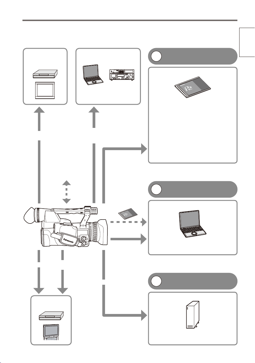
Outline of operations
This unit is compatible with P2 (Professional Plug-in) cards.
The P2 card has a large capacity with a high transfer rate, and allows you sophisticated movie-making on
this handy camera, including HD (High Denition) recording and smooth editing/dubbing.
Video
equipment/
Monitor
BNC cable
(HD-SDI)
The setting values
such as the user le
are saved to and read
from the SD memory
card.
Computer/
Memory card recorder
The contents can be transferred
as a data stream (digital
dubbing).
IEEE1394
(Windows/
Macintosh)
P2 card
P2 mode shooting and
1
playback (Pages 24 and 62)
P2 card
You can use the following features:
HD (High Denition) recording
•
Multi format recording
•
Variable frame rates
•
Slow & quick motion recording
Maximum 4 channel uncompressed
•
digital audio recording
DV recording (576i)
•
For details on how to handle recorded
data, see Page 121.
PC mode (Page 80)
2
Computer
Before use
AV cable
Component
video cable
Video equipment/
Television
USB2.0
(Windows)
IEEE1394
(Macintosh)
IEEE1394 (SBP-2*)
*Serial Bus Protocol-2
The data (le) is transferred for nonlinear
editing on your computer or other unit.
1394 host mode (Page 82)
3
External hard disk
The unit directly controls the external hard disk
drive, and transfers the data (le) to it.
7
Page 8

Precaution for use
Always take some trial shots before actual shooting.
When shooting important events (such as weddings), always take some trial shots and check that the
•
sound and images have been recorded properly before actual shooting.
Be sure to check and set the calendar and time zone.
These settings affect the control and playback sequence of the recorded contents. Before making a
•
recording, set and check the calendar and time zone. (Page 23)
Panasonic makes no guarantees for your recordings.
Please understand that Panasonic makes no guarantees for your recordings in cases where images
•
and/or sound were not recorded as you intended due to problems with the camera-recorder.
Respect copyrights
Copyright laws forbid the use of video and audio material you have recorded for any purpose other than
•
your own personal enjoyment. Remember that restrictions apply to the shooting of cer tain material even if
it is intended for private use.
Caution regarding laser beams
The CCD may be damaged if it is subjected to light from a laser beam.
•
When using the camera-recorder in locations where laser irradiation equipment is used, be careful not to
allow the laser beam to shine directly on the lens.
Notes when connecting a 1394 cable
Windows:
•
Before connecting, turn off the main unit power, and check the shape and orientation of the terminal.
Macintosh:
•
After turning on the power of the Apple Macintosh computer, check the shape and orientation of the
terminal, and then connect the cable.
(Pages 76, 77)
Media that can be used in this unit
The following media can be used in this unit. For details, refer to the respective pages.
P2 card (Pages 24, 121)
•
SD/SDHC memory cards (Pages 28, 122)
•
Mounting the camera-recorder on a tripod
The tripod mounting hole is 5.5 mm deep. Do not force the tripod screw beyond this depth.
You can damage the camera-recorder if you use any screw other than 1/4-20UNC.
For other usage notes, see Page 116.
8
Attach the tripod to the tripod hole.
Page 9
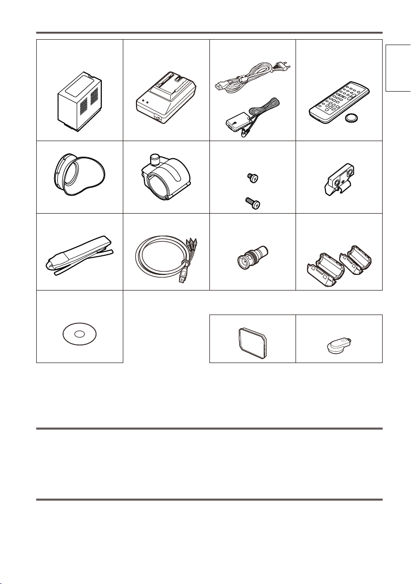
Accessories
Battery *1 AC Adapter AC power supply cord/
DC cord
Eye cup Microphone holder Screws for microphone
holder
6-mm screws (2)
12-mm screws (2)
Shoulder belt Component video cable PIN-BNC conversion
plugs (3)
CD-ROM The following accessories are attached to the
camera-recorder.
Lens hood INPUT terminal cover (2)
Wireless remote control
and battery (CR2025)
Microphone holder
adapter
30-mm ferrite core (2)*2
35-mm ferrite core (2)*2
Before use
*1 For part numbers for the battery, see “Optional units”. (see below)
*2 When using a 1394 cable (sold separately) or a USB cable (sold separately), attach ferrite cores to the
both ends of the cable. (Page 76)
Optional units
XLR microphone
•
AG-MC200G
Battery
•
CGA-D54 (5400 mAh: equivalent to accessory battery)
About this manual
Note concerning illustrations in these instructions
Illustrations (camera-recorder, menu screens, etc.) in these operating instructions differ slightly from the
•
actual camera-recorder.
References
References are shown as (Page @).
•
9
Page 10
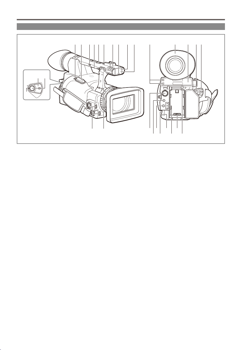
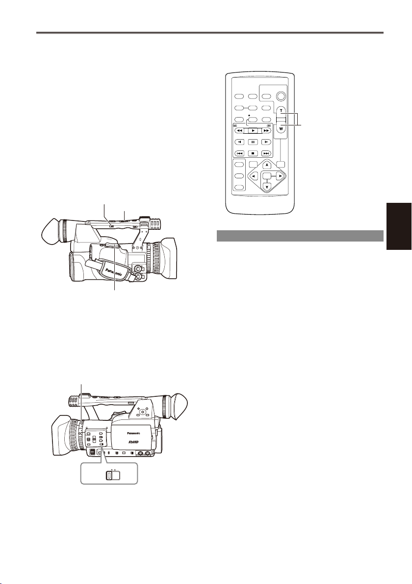
Description of parts
POWER
ON
OFF
Right side and rear side
3 4 5 7 8 9 10 11 12
6
1 2
13
14
1 POWER switch (Page 18)
2 START/STOP button (Page 24)
3 REC CHECK button (Page 24)
4 Zoom button (Page 29)
5 HANDLE ZOOM switch (Page 29)
6 Recording enable/disable switch (Page 39)
7 Handle zoom button (Page 29)
8 Handle START/STOP button (Page 24)
9 Built-in stereo microphone (Page 50)
10 Tally lamp (Front) (Page 18)
11 Remote control sensor (Front) (Page 17)
12 White balance sensor (Page 38)
12171615
18 202122
19
13 INPUT 1/2 (audio input) switch (Page 50)
14 Zoom ring pin hole (Page 29)
15 P2 card access lamp (x 2) (Page 25)
16 Viewnder (Page 19)
17 P2 card/SD memory card slot (cover)
(Pages 24 and 28)
18 SCENE FILE dial (Page 52)
19 SLOT SEL button (Page 43)
20 Mode button (Page 24)
21 Remote control sensor (Rear) (Page 17)
22 Tally lamp (Rear) (Page 18)
23 Mode lamp (Page 24)
24 Power terminal (Page 15)
25 Battery release button (Page 15)
24
23 25
10
Page 11
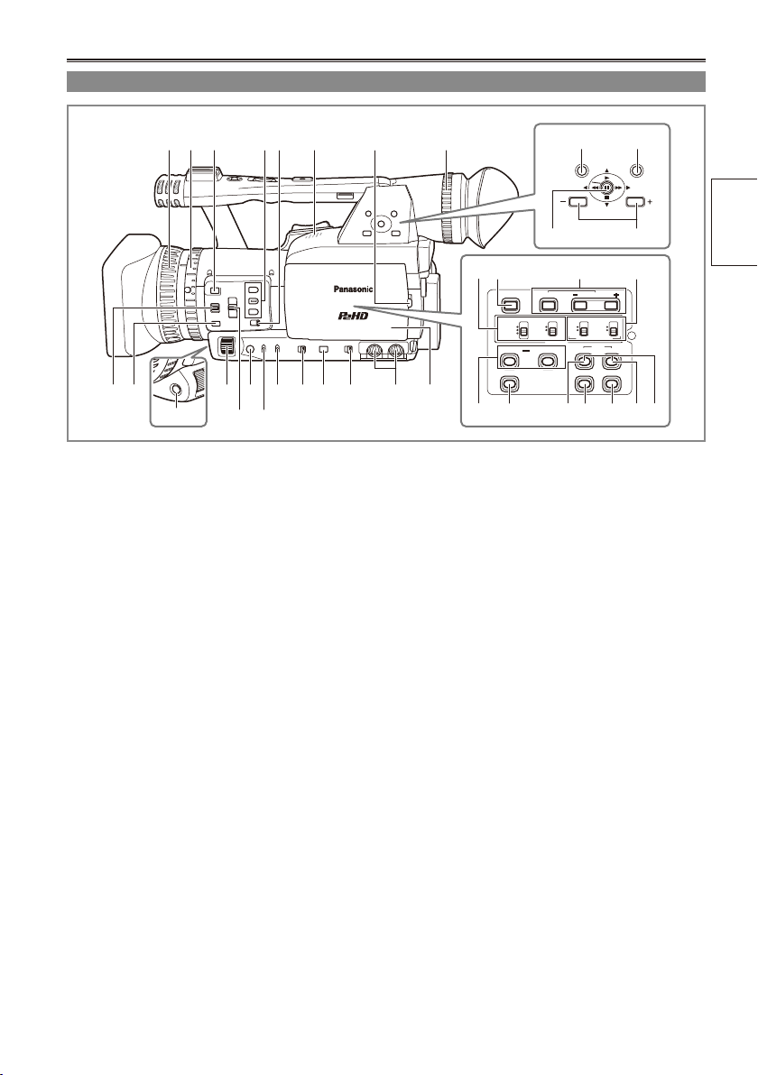
Left side
BARS
CH1 SELECT
COUNTER RESET/TC SET
REC
CH2 SELECT
AUDIO
INT(L)
INPUT1
INPUT2
SHUTTER
SPEES SELECT
INT(R)
INPUT2
INPUT1
MIC POWER+48V
ON
OFF
INPUT2
ON
OFF
LCD
ZEBRA
EVF DTL
OIS
WFM
MENU
PUSH-SET
PAGE/AUDIO MON/VAR
THUMBNAIL
AWB
3 4 652
1
11
12
14 161517 18 19 2010 21
13
9
1 Focus ring (Page 34)
2 Zoom ring (Page 29)
If you don’t need the zoom ring pin, t it
into the provided zoom ring pin hole (14 on
page 10) so that you don’t loose it.
3 FOCUS ASSIST button (Page 35)
4 USER button (Page 41)
5 ZOOM switch (Page 29)
6 Built-in speaker (Page 74)
7 OPEN button (Page 20)
8 Diopter adjustment dial (Page 19)
9 FOCUS switch (Page 34)
10 PUSH AUTO button (Page 34)
11 AWB button (Page 37)
12 IRIS dial (Page 35)
13 ND FILTER switch (Page 36)
14 IRIS button (Page 35)
15 GAIN switch (Page 36)
16 WHITE BAL switch (Page 37)
17 FUCUS RING (FOCUS/IRIS) switch
(Page 34)
18 DISP/MODE CHK button (Page 40)
7
8
22 23
24 25
27
26 2928
33 34
32 353130
19 AUTO/MANUAL switch (Page 24)
20 AUDIO LEVEL knobs (CH1, CH2) (Page 51)
21 LCD monitor (Page 20)
22 MENU button (Page 93)
23 THUMBNAIL button (Page 65)
24 Operation lever (Pages 62 and 93)
25 PAGE/AUDIO MON/VAR button (Pages 42
and 73)
26 CH1, CH2 SELECT switch (Page 50)
27 BARS button (Page 41)
28 SHUTTER, SPEED SELLECT +/- button
(Page 48)
29 INPUT1, 2 switch (MIC POWER +48 V)
(Page 50)
30 COUNTER - RESET/TC SET button
(Page 57)
31 LCD button (Page 22)
32 ZEBRA button (Page 39)
33 EVF DTL button (Page 20)
34 WFM button (Page 42)
35 OIS button (Page 41)
36 MCR REC button (Page 85)
Functions when the ZEBRA button (32) and
OIS button (35) are pressed at the same time.
parts
Description of
36
11
Page 12
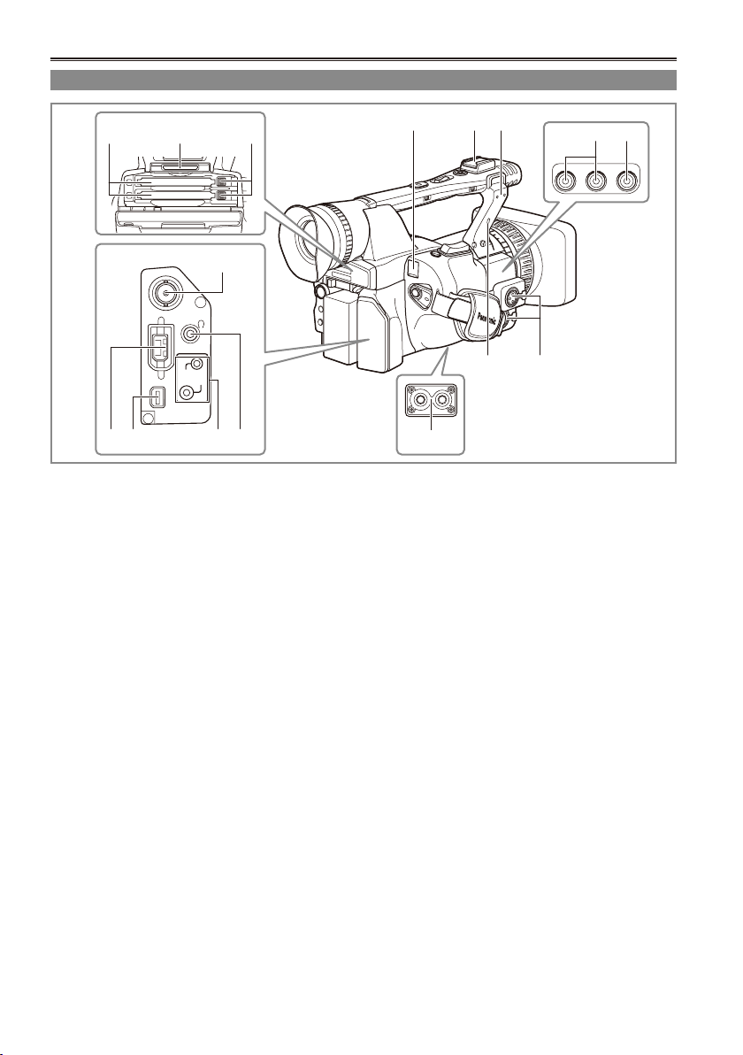
Description of parts (continued)
SDI
OUT
1394
CAM REMOTE
FOCUS IRIS
ZOOM S/S
COMPONENT
OUT
Terminals and mounting parts
54 6
7
1098 11
1 USB terminal (Mini-B) (Page 76)
2 Light shoe
3 Microphone shoe (Page 75)
4 P2 card slots (Page 24)
5 SD memory card slot (Page 28)
6 P2 card eject buttons (Page 27)
7 SDI OUT terminal (Page 79)
8 1394 terminal (Pages 76 and 77)
9 COMPONENT OUT terminal (Page 79)
10 CAM REMOTE jack*
FOCUS/IRIS (3.5 mm mini jack)
You can connect a remote control unit to
control the FOCUS and IRIS (aperture).
ZOOM S/S (2.5 mm super mini jack)
You can connect a remote control unit to
control zoom and start/stop of recording.
11 Headphone jack (3.5 mm stereo mini jack)
(Page 75)
12 Tripod hole (Page 8)
1 2 3
13
14
1615
12
13 Security Lock opening
Use this opening to attach a security cable.
For details on how to attach the cable, see the
Operating Instructions supplied with the cable.
The security lock and security cable are
designed to prevent theft, but Panasonic will
not accept any liability for damages resulting
from theft.
14 INPUT 1/2 terminal (XLR, 3 pin) (Page 75)
15 AUDIO OUT CH1/CH2 terminals (Page 79)
16 VIDEO OUT terminal (Page 79)
12
* Do not connect any equipment except the remote
controller to the CAM REMOTE jack.
Connecting any equipment other than the remote
control may cause the image brightness to
change and/or the images to appear out of focus.
Page 13
OSD
COUNTER
RESET TITLE
STILL ADV
PAUSE
STILL ADV
INDEX
SELECT
STORE
OFF/ON
P.B.DIGITAL
VAR.
SEARCH
VOL +
-
PB.
ZOOM
MENU
SET
ITEM
STOP INDEX
MULTI/
P-IN-P
REC A.DUB
PLAY/REW FF/
ZOOM
DATE/
TIME
PHOTO
SHOT
START/
STOP
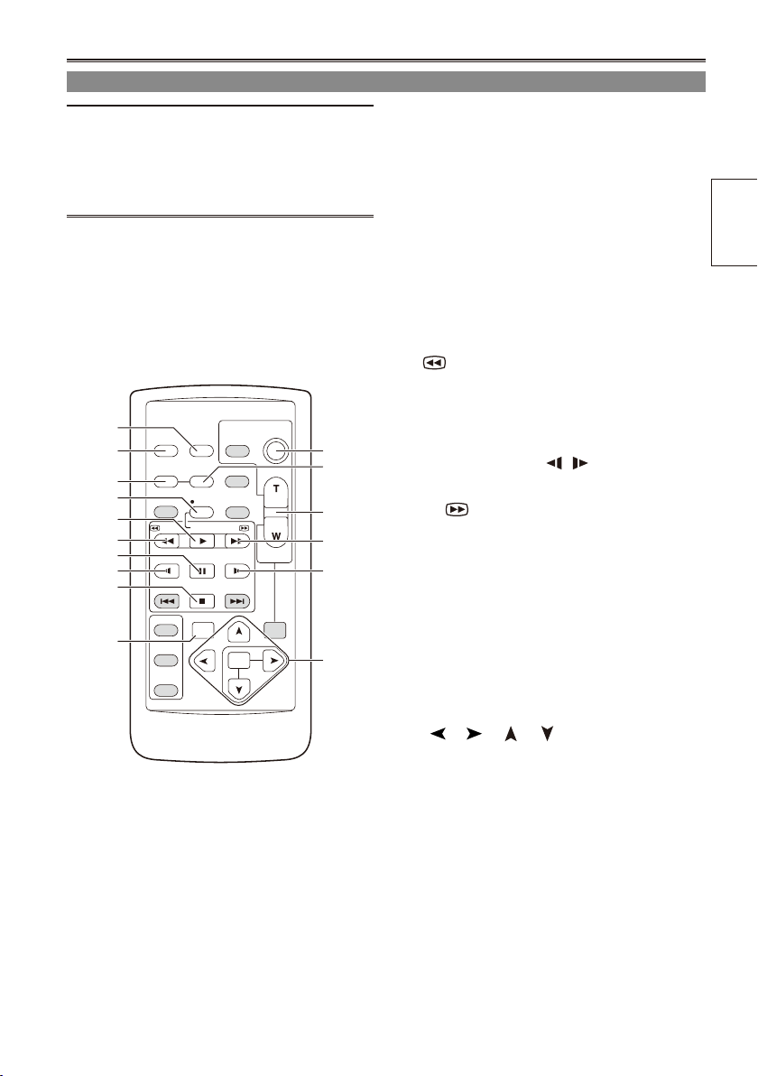
Remote control
The following buttons are for functions that
cannot be executed on the camera-recorder.
• PHOTO SHOT • TITLE • A.DUB
• MULTI/P-IN-P • SELECT
• STORE • OFF/ON
• PB.ZOOM • INDEX
1
2
3
5
6
7
8
9
10
14
12
4
13
11
9
15
1 DATE/TIME button (Page 74)
2 OSD button (Page 74)
3 COUNTER button (Page 57)
Same function as the COUNTER button on the
main unit.
4 COUNTER RESET button (Page 57)
Same function as the COUNTER RESET
button on the main unit.
5 REC button (Page 85)
Operation buttons
6 PLAY button ( q) (Pages 62 and 85)
7 /REW button (t ) (Page 62)
8 PAUSE button ( h ) (Page 62)
Like the operation buttons of the camera,
MENU operations are performed using SET
button.
9 STILL ADV button ( , ) (Page 17)
10 STOP button ( g ) (Page 62)
11 FF/ button ( y) (Page 62)
Buttons for shooting and volume control
12 START/STOP button (Page 24)
Same function as the START/STOP button on
the main unit.
13 ZOOM/VOL buttons (Page 29)
14 VAR. SEARCH button (Page 73)
15 MENU button (Page 93)
Functions the same as the MENU button on
the camera.
[ ], [ ], [ ], [ ] buttons
Function the same as the Operation lever on
the camera.
parts
Description of
13
Page 14
The battery
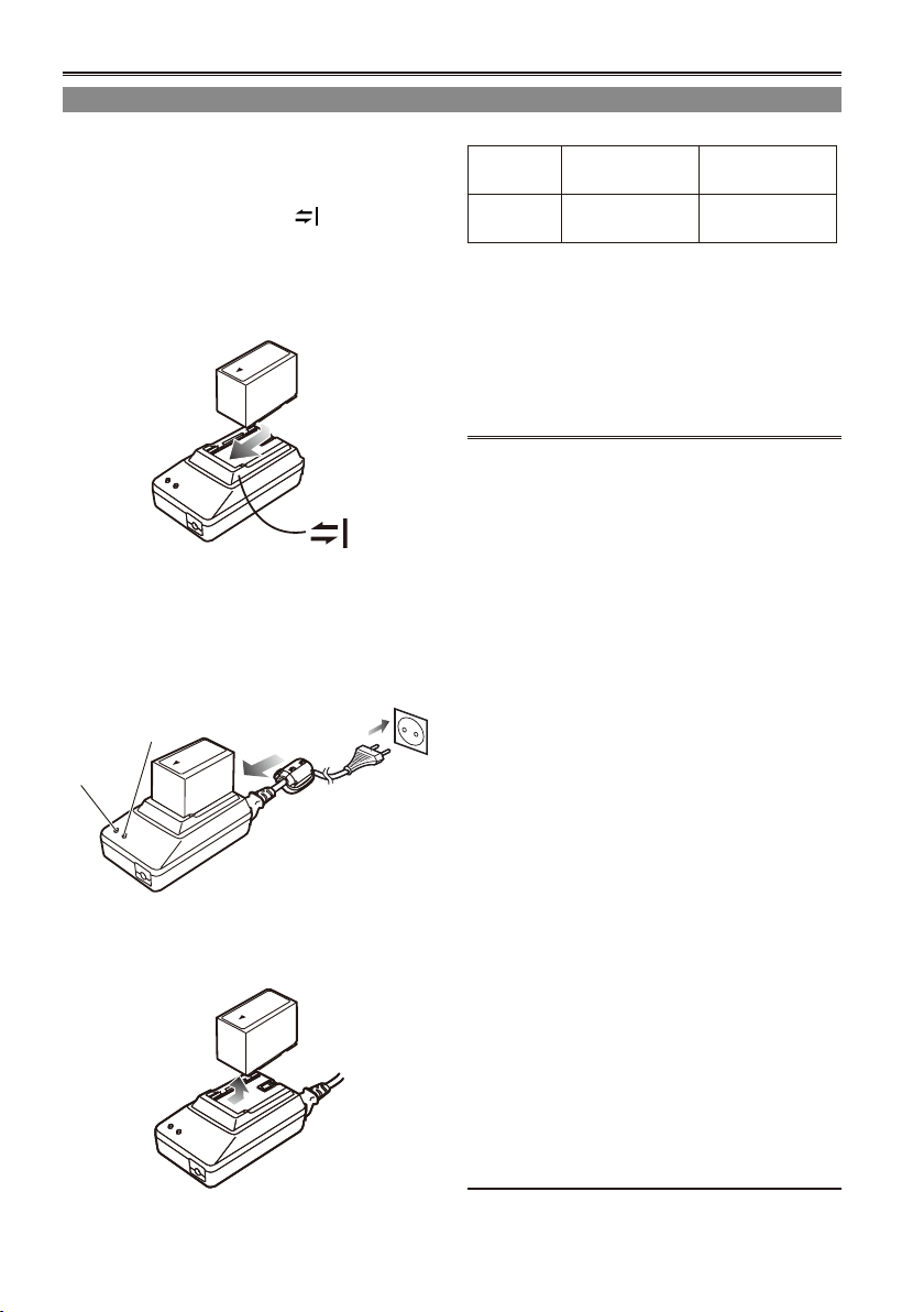
Charging
Before using the battery, fully charge it with the AC
adapter.
Keep a spare battery with you.
1 Align the battery with the marking on
the AC adapter, place it at, and slide it in
the direction shown below.
You cannot charge the battery if the DC cord
•
is connected to the DC OUT connector, so
disconnect it rst.
2 Plug the AC cord into the power outlet.
The POWER lamp and CHARGE lamp on
•
the AC adapter light, and charging begins.
If the CHARGE lamp does not light when
•
attached, detach the battery and then attach
it again.
CHARGE
POWER
When the battery is charged, the CHARGE
•
lamp on the AC adapter goes out.
3 Slide the battery and remove it.
Recording time of included battery
Capacity
5400 mAh
The times given above are approximate for when
•
scenes are shot in the DVCPRO HD mode while
not using the LCD monitor.
The times apply when the ambient operating
•
temperature is 20°C and humidity is 60%.
Charging may take longer at other temperatures
and humidity levels.
Keep metal objects (such as necklaces
•
and hairpins) away from the battery.
Shortcircuiting may occur across the
terminals, causing the battery to heat up,
and you may seriously burn yourself if you
touch the battery in this state.
The battery becomes hot while it is being
•
used or charged. The camera-recorder itself
also becomes hot during use.
The recordable time reduces if you repeatedly
•
start and stop recording.
Discharge the battery before storing it. When
•
storing it for an extended time, charge it at
least once a year, use up its charge in the
camerarecorder, and then store it again.
If the battery is extremely hot or cold, the
•
CHARGE lamp will blink several times before
charging starts.
If the CHARGE lamp continues to blink even
•
when the battery temperature is normal, there
may be something wrong with the battery or
AC adapter. Contact your dealer.
The battery takes longer to charge when it is
•
warm.
The AC adapter can interfere with radio
•
reception so keep radios at least 1 meter
away from it.
The AC adapter may make some noise when
•
you are using it, but this is normal.
You cannot charge the battery when
•
supplying power to the camera-recorder from
the AC adapter.
Operation of battery pack CGR-D16 (1600
•
mAh) (sold separately) is not guaranteed.
Recharging
time
Approx. 330
min.
Continuous
recording time
Approx. 160
min.
14
Page 15
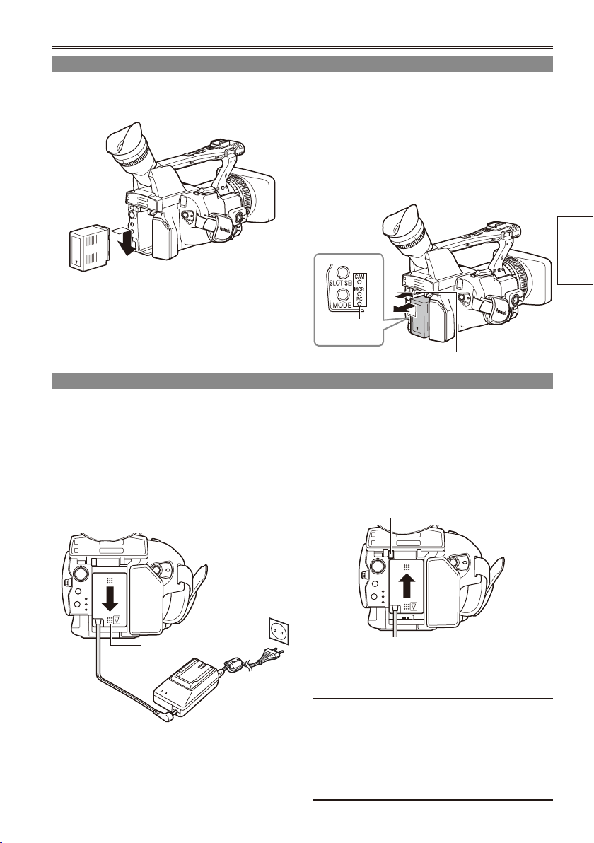
Installing and removing the power supply
Installing and removing the battery
Installation
1 Insert the battery until it clicks into place.
Removal
1 Set the POWER switch to OFF, and check
2 While pressing the battery release button,
Connecting and disconnecting the power cord
Installation
1 Connect the DC cord to the AC adapter.
Removal
1 Set the POWER switch to OFF, and check
2 Plug the AC power supply cord into the
power outlet.
2 Slide the DC cord’s battery connector to
3 Slide the DC cord’s battery connector to
the direction of the arrow until it clicks into
place.
that the mode lamp is off.
raise up the battery to remove it.
Support the battery with your hand to ensure
•
that it will not fall.
Mode lamp
Battery release button
that the mode lamp is off.
the direction of the arrow while pressing
the battery release button.
Battery release button
Preparation
DC cord’s battery
connector
3 Disconnect the AC power supply cord from
the power outlet.
CAUTION:
You cannot charge the battery when
•
supplying power to the camera-recorder from
the AC adapter.
Disconnect the AC power supply cord from
•
the power outlet when the unit is not going to
be used.
15
Page 16
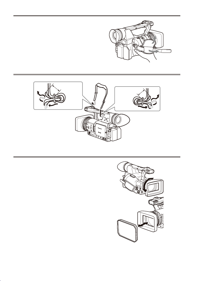
Adjusting the hand strap
Adjust the hand strap to suit your hand.
1 Open the cover and adjust the length.
2 Close the cover.
Make sure the cover is fully closed.•
Attaching the shoulder strap
Attach the shoulder strap and use it as a precaution against dropping the camera.
20 mm or more
20 mm or more
Detaching and attaching the lens hood
Detaching the lens hood
Turn the lens hood counterclockwise to detach it.
•
Attaching the lens hood
Turn the lens hood clockwise until it clicks to
•
secure it in position.
Be sure to attach the lens hood cap to protect the
•
lens when not in use.
16
Page 17
The remote control
OSD
COUNTER
RESET TITLE
STILL ADV
PAUSE
STILL ADV
INDEX
SELECT
STORE
OFF/ON
P.B.DIGITAL
VAR.
SEARCH
VOL+
-
PB.
ZOOM
MENU
SET
ITEM
STOP INDEX
MULTI/
P-IN-P
REC A.DUB
PLAY/REW FF/
ZOOM
DATE/
TIME
PHOTO
SHOT
START/
STOP
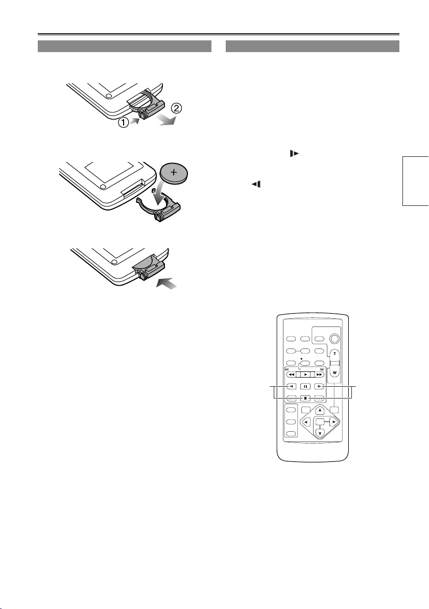
Insert the battery
1 Push the catch in the direction shown by
arrow to remove the holder.
2 Insert the battery with the “+” marked side
facing up.
3 Return the holder to its original position.
When the battery (CR2025) has run out, replace
•
it with a new one. (The battery lasts about one
year, depending on the frequency of use.)
If the remote control unit fails to work even when
it is operated near the camera-recorder’s remote
control sensor, the battery has run out.
Keep the battery out of the reach of children.
•
Remote control setup
When using two camera-recorders simultaneously,
set this camera-recorder and the remote control
to either “operation mode 1” or “operation mode 2”
so the remote control does not operate the wrong
camera-recorder by mistake.
Setting
Wireless remote control
•
Press the MCR operation buttons STOP ( g )
and STILL ADV ( ) at the same time to set the
remote control unit for use in “operation mode 1”.
Alternatively, press the STOP ( g ) and STILL
ADV ( ) buttons at the same time to set the
remote control unit for use in “operation mode 2”.
When the battery in the remote control unit is
replaced, the remote control unit is set for use in
“operation mode 1”.
Camera
•
In the setup menus, OTHER FUNCTIONS
screen, REMOTE, set to 1 or 2. (Page 109)
If different settings are used for the camerarecorder and remote control unit, “REMOTE” lights
in red on the viewnder and LCD monitor.
Operation
mode 2
Operation
mode 1
Preparation
17
Page 18
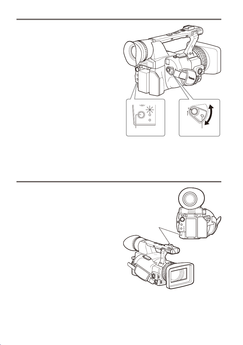
Turn on/off the camera
SLOT SEL
MODE
CAM
MCR
PC
POWER
ON
OFF
While pressing the lock release, turn the POWER
switch.
Turn on the camera:
The mode lamp (CAM) lights red (CAM mode) and
the camera is now in the shooting standby mode.
Turn off the camera:
The mode lamp (CAM) goes out.
Power saving mode
•
When the camera is left idle in pause mode
for about 5 minutes, it will behave as follows
depending on what POWER SAVE settings
have been made in the setting menu OTHER
FUNCTIONS screen (Page 111).
ON: The camera-recorder turns off automatically.
OFF: The camera-recorder does not turn off
automatically.
See the setup menus, OTHER FUNCTIONS
screen, POWER SAVE (Page 111) for details.
When the operation mode buttons ash in
•
sequence starting with the top one and the power
then goes off, it means that there is no charge left
in the battery. Recharge the battery.
Tally lamp
Mode lamp
Mode button
Lock release
The tally lamp can be made to light up during
shooting by selecting “ON” as the REC LAMP
setting in the OTHER FUNCTIONS screen.
(Page 110)
When the camera-recorder is in any of the
following states, the tally lamp blinks.
When an operation initiated by the remote control
•
unit has been received (8 blinks/sec.)
When the remaining battery capacity runs out (4
•
blinks/sec.)
When the available recording space on the P2
•
card or the battery power is low (1 blink/sec.)
When removing the P2 card during access (4
•
blinks/sec.)
When there is no recording space left on the P2
•
card (4 blinks/sec.)
18
Tally lamp
Page 19
Viewnder
POWER
ON
OFF
This camera has two viewnders; one is a
miniature LCD in the viewnder and the other is a
retractable 3.5-inch LCD.
Use the viewnder that best suits the application
and shooting conditions.
The brightness and hue may differ between the
•
images appearing on the viewnder and LCD
monitor and those displayed on a TV monitor.
To see how the nal images will appear, check
them on a TV monitor.
Images are always displayed on the viewnder.
•
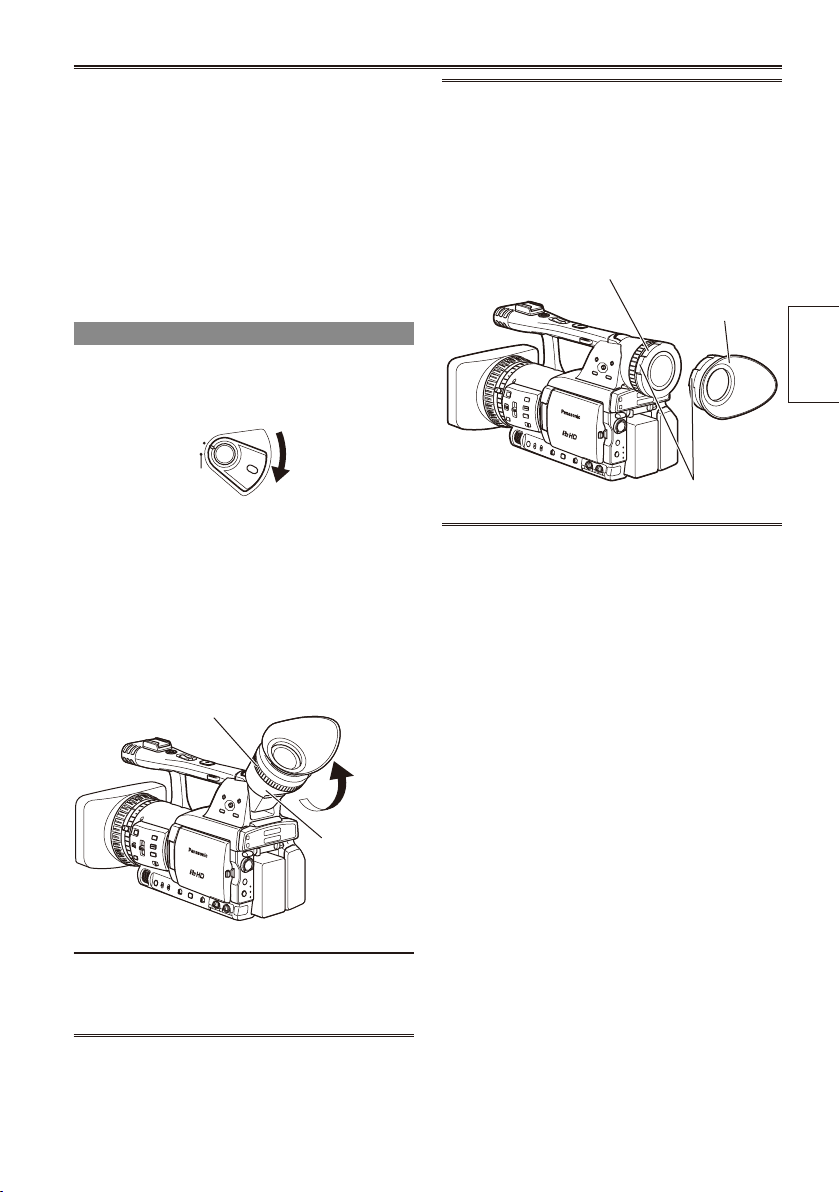
Using the viewnder
1 Set the POWER switch to ON and check
that images appear in the viewnder.
Keep the LCD monitor closed.
•
2 Adjust the viewnder’s angle so that the
screen is positioned where it is easiest to
see.
You can move the view nder out to about 90
•
degrees perpendicular to the camera.
3 Adjust the diopter adjustment lever so
that you can see the characters on the
viewnder screen clearly.
Viewnder diopter dial
Fitting the eye cup
Attach the eye cup by aligning the projections
on the eye cup holder and eye cup and tting
them together.
Turning the eye cup after attaching it may
•
cause the eye cup holder to come off. If the
eyecup holder does come off, see “Cleaning
the Viewnder” (Page 119) for details on how
to ret it.
Eye cup holder
Eye cup
Projection
Preparation
Eye piece
Do not point the eye piece at the sun or
other strong light source.
Light concentrated by the lens could damage
•
internal components and poses a re hazard.
19
Page 20
BARS
CH1 SELECT
RESET/TC SET
REC
CH2 SELECT
AUDIO
INT(L)
INPUT1
INPUT2
SHUTTER
SPEES SELECT
INT(R)
INPUT2
INPUT1
MIC POWER+48V
ON
OFF
INPUT2
ON
OFF
LCD
ZEBRA
EVF DTL
OIS
WFM
COUNTER
Viewnder (continued)
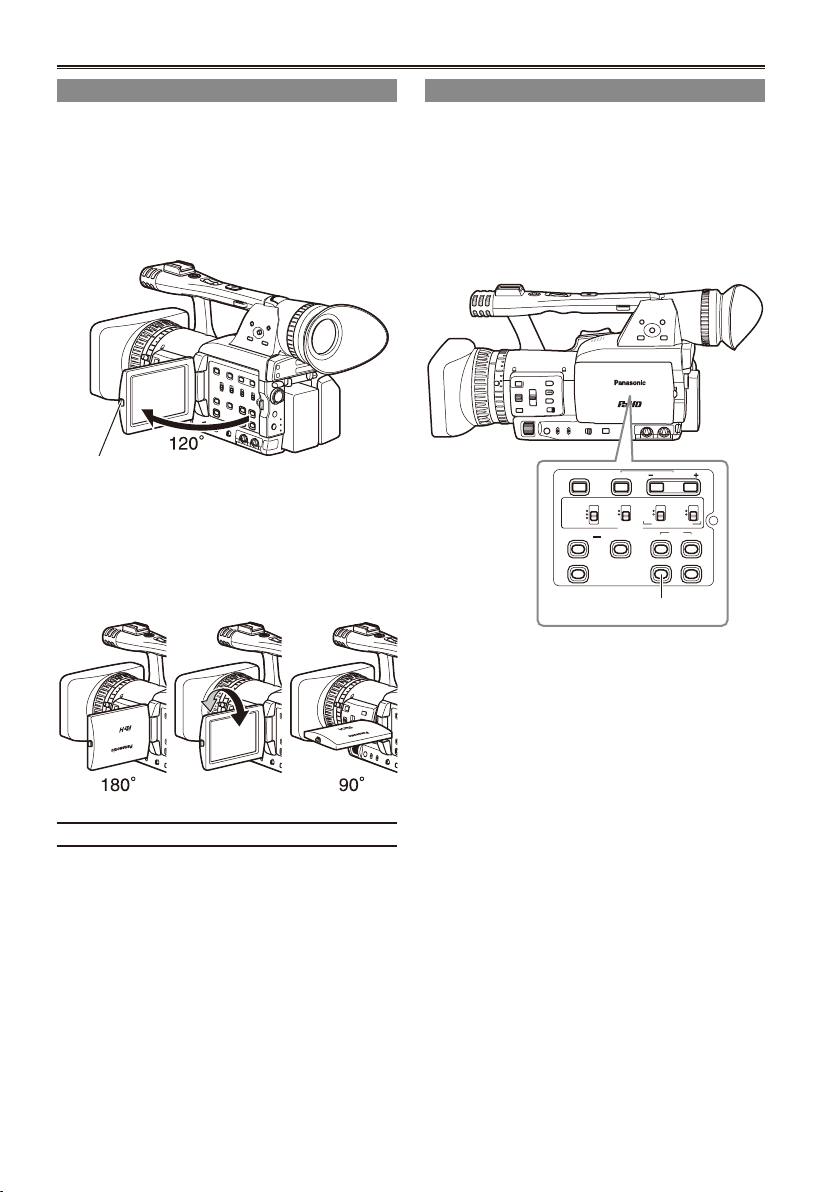
Using the LCD
1 Set the POWER switch to ON.
2 Hold down the OPEN button to open the
LCD monitor.
It can open out to 120 degrees. Do not try
•
to open it further as this will damage the
camera.
OPEN button
3 Position the LCD monitor where it is
easiest to see.
The monitor can be rotated 180 degrees
•
toward the lens and 90 degrees toward you.
Do not apply unnecessary force to the
•
open LCD. This can damage the camera.
Emphasizing outlines
Emphasizing the outlines of the images you see
in the viewnder or on the LCD makes it easier to
focus.
Emphasizing the outlines does not effect the
images you shoot.
1 In CAM mode, press EVF DTL.
“EVF DTL ON” appears on the screen for
about 2 seconds.
EVF DTL button
Press EVF DTL again to return to the original
display. “EVF DTL OFF” appears on the screen
for about 2 seconds.
Ensure the LCD is fully closed.
•
20
Page 21
Adjusting the screen display
DISPLAY SETUP
PUSH MENU TO RETURN
ZOOM·FOCUS NUMBER
ON
TOTAL
PARTIAL
NORMAL
–– ––
–– ––
MIRROR
CARD/BATT
LCD SET
EVF SET
P2CARD REMAIN
OTHER DISPLAY
LCD BACKLIGHT
SELF SHOOT
PUSH MENU TO RETURN
EVF COLOR LEVEL
EVF BRIGHTNESS
[– ] – –– –– ––– +– –– ––– –– [ +]
EVF CONTRAST
[– ] – –– –– ––– +– –– ––– –– [ +]
[– ] – –– –– ––– +– –– ––– –– [ +]
EVF SET
PUSH MENU TO RETURN
EVF COLOR LEVEL
EVF BRIGHTNESS
[– ] – –– –– ––– +– –– ––– –– [ +]
EVF CONTRAST
[– ] – –– –– ––– +– –– ––– –– [ +]
[– ] – –– –– ––– +– –– ––– –– [ +]
EVF SET
1 Set the POWER switch to ON. (Page 18)
2 Press the MENU button.
For menu operation (Page 93)
•
You can also use the menu buttons on the
•
remote control. (Page 13)
3 Viewnder adjustments
Select YES under EVF SET on the setting
menu DISPLAY SETUP screen.
LCD monitor adjustments
Set YES under LCD SET on the setting menu
DISPLAY SETUP screen.
5 Push the Operation lever in the
or q
w
direction to make adjustment.
6 Press MENU three times to exit the menus.
You can return the settings for EVF SET and
•
LCD SET to the factory settings by selecting
the item and pressing COUNTER RESET (if it
is possible to change the item at that time).
The viewnder display can be in color or black
•
and white. (See the setup menus, DISPLAY
SETUP screen, EVF COLOR.) The resolution
is the same for both of them.
Preparation
4 Push the Operation lever in the
direction to select the item.
e
or r
21
Page 22
LCD
LCD
LCD
Viewnder (continued)
Adjusting the backlight
The steps below show how to set the brightness of
the LCD monitor to one of three possible levels.
1 Select LCD BL under LCD on the setting
menu SW MODE screen.
This assigns LCD BL to the LCD button.
2 Press the LCD button.
Each press of the button switches backlight
brightness in the following order: NORMAL
(standard) " LOW (dark) " HIGH (bright) "
NORMAL.
These settings persist even when the
•
camera-recorder is turned off.
Flipping images vertically and
horizontally
Use this function to ip an image vertically
or horizontally to check the aspect ratio or
composition on the LCD monitor.
This feature affects only the image in the viewnder
or on the LCD monitor, not the recorded image.
1 Select LCD REV under LCD on the setting
menu SW MODE screen.
This assigns LCD REV to the LCD button.
Switching between overscan and underscan
Use this function to underscan or overscan the
image shown in the viewnder or on the LCD
monitor.
1 Select OVERSCAN under LCD on the
setting menu SW MODE screen.
This assigns OVER SCAN to the LCD button.
2 Press the LCD button.
This button toggles between overscan and
•
underscan at each press.
The unit returns to underscan mode the next
•
time it is powered up.
In overscan mode, a frame appears on the
•
screen.
2 Press the LCD button.
This button toggles between the normal and
•
ipped image at each press.
No screens are displayed when the image
•
is ipped.
The unit returns to normal image mode the
•
next time it is powered up.
22
Page 23
Setting the calendar
OTHER FUNCTIONS
PUSH MENU TO RETURN
CLOCK SET –– ––
+0: 00
OFF
–– ––
00012H
00012H
–– ––
MIRROR
TIME ZONE
OPERATION
EVF SET
POWER SAVE
MENU INIT
OPERATION
SELF SHOOT
OTHER FUNCTIONS
PUSH MENU TO RETURN
CLOCK SET ––– –
YES
OFF
–– ––
00012H
00012H
–– ––
MIRROR
TIME ZONE
OPERATION
EVF SET
POWER SAVE
MENU INIT
OPERATION
SELF SHOOT
CLOCK SET
PUSH MENU TO RETURN
YEAR 2008
OCT
01
12
00
MONTH
+/– : PUSH y / t
DAY
HOUR
MIN
SEL : PUSH q / g
CLOCK SET
PUSH MENU TO RETURN
YEAR 2008
OCT
01
12
00
MONTH
+/– : PUSH y / t
DAY
HOUR
MIN
SEL : PUSH q / g
CLOCK SET
PUSH MENU TO RETURN
YEAR 2008
DEC
01
12
00
MONTH
+/– : PUSH y / t
DAY
HOUR
MIN
SEL : PUSH q / g
CLOCK SET
PUSH MENU TO RETURN
YEAR 2008
DEC
25
17
20
MONTH
+/– : PUSH y / t
DAY
HOUR
MIN
SEL : PUSH q / g
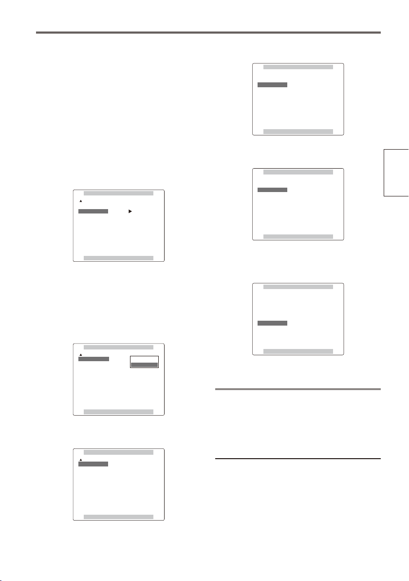
The CLOCK SET value is recorded in the contents
(clip), and affects the sequence of playback of the
thumbnails. Before carrying out recording, be sure
to check and set CLOCK SET and TIME ZONE.
This shows you how to adjust the calendar to 5:20
PM on December 25, 2008.
1 Set the POWER switch to ON. (Page 18)
2 Press the MENU button.
3 Push the Operation lever in the
direction to set the time difference from
Greenwich Mean Time under TIME ZONE
on the setting menu OTHER FUNCTIONS
screen. (Page 110)
(Example of MENU in the CAM mode)
For menu operation (Page 93)
•
You can also use the menu buttons on the
•
remote control. (Page 13)
e
or r
6 Push the Operation lever in the
direction
r
to move to the MONTH setting.
7 Push the Operation lever in the
or q
w
direction to set MONTH to DEC.
8 Set DAY, HOUR, and MIN using the method
shown in steps 4 and 5.
This is a 24-hour clock.
•
Preparation
4 In the setup menus, OTHER FUNCTIONS
screen, CLOCK SET, select YES.
5 Push the Operation lever in the
direction to set YEAR to 2008.
Choose a year between 2000 and 2030.
w
or q
9 Press MENU three times to exit the menus.
The clock can vary in accuracy so check that
•
the time is correct before shooting.
When using the camera overseas, do not
•
set the CLOCK SET option to the local time,
but instead enter the time difference from
Greenwich mean time according to TIME
ZONE.
23
Page 24
Basic shooting operations
3
4
1
POWER
ON
OFF
1
2
3
POWER
ON
OFF
POWER
ON
OFF
AUTO
MANUAL
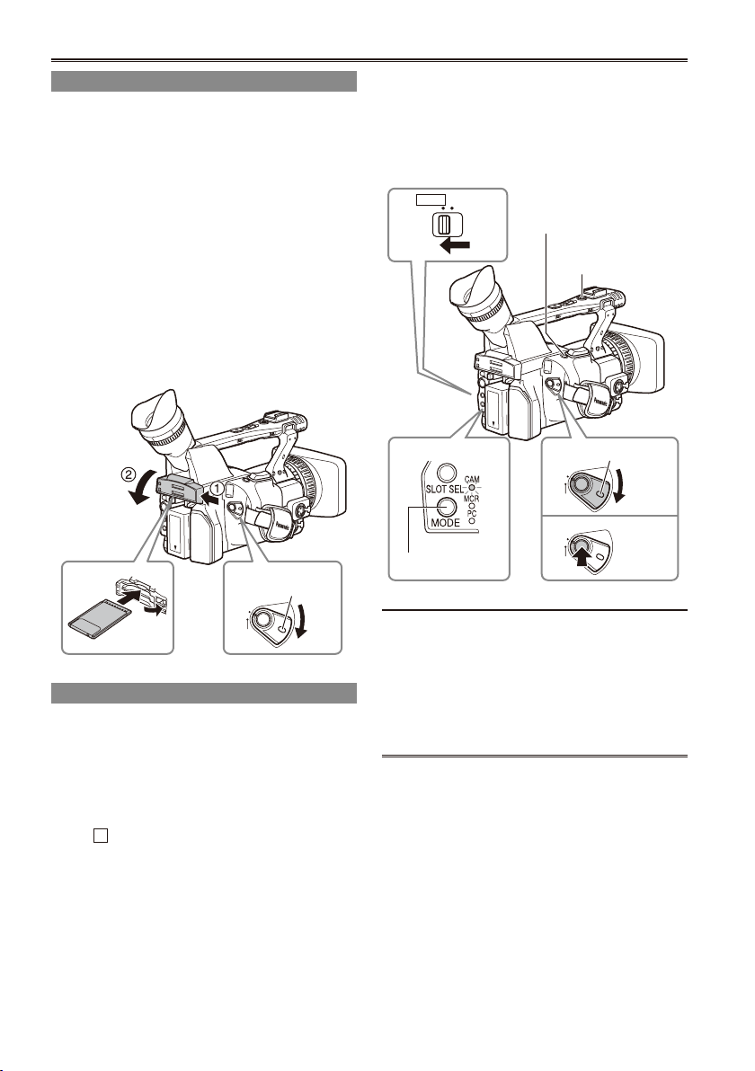
Preparing to shoot
1 Set the POWER switch to ON. (Page 18)
2 Lift up the viewnder, press the side of the
card slot cover (A), and slide the cover (B)
to open it.
3 Insert the P2 card securely in the card slot.
4 Push the P2 card eject button to the
direction of the arrow, and close the card
slot cover.
There are two card slots.
•
Be absolutely sure to close the card slot
•
covers to keep the dust out.
Do not remove the P2 card while the P2 card
•
access lamps are blinking orange. (Page 25)
Lock
release
3 Press the START/STOP button (Red) on the
POWER switch to start shooting.
Press again to return to the camera to the
•
shooting standby mode.
Use the handle START/STOP button to make
•
it easier to shoot from low angles.
LCD
side
Mode lamp
Mode button
REC CHECK
button
Handle START/STOP
button
Lock release
Shooting in auto mode
1 Turn the POWER switch to ON. (Page 18)
Check that the mode lamp (CAM) is lighted
•
red.
2 Switch the AUTO/MANUAL switch to AUTO
to select auto mode.
“ A ” appears on the viewnder and LCD
•
screens.
The focus, gain, iris and white balance are
•
adjusted automatically.
24
Under the following circumstances, even if you
press the STOP button it may take some time
until the writing to the P2 card nishes. For this
reason, the operation will not be acknowledged
if you press the START button too soon.
Stopped after only a short recording time
•
Stopped immediately after the recording has
•
moved to a second P2 card
Page 25
Checking photos taken (REC CHECK)
In the shooting pause mode, press the REC
CHECK button.
This plays back about 2 seconds of the video and
audio of the most recently recorded clip before
returning to pause mode.
Note that this REC CHECK portion will also be
•
recorded to any equipment you have set up to
make backup recordings.
The REC CHECK function does not work in PC
•
and MCR mode.
The HD recording(1080i/50i) settings are
already made in the default mode. (To view the
current settings, see Page 40.)
PC mode (1394 HOST)
Lights green:
Access standby.
Blinks orange:
Data is now being accessed.
Off:
Cards have not been inserted or formatted.
Insertion of incompatible card.
P2 card access lamps
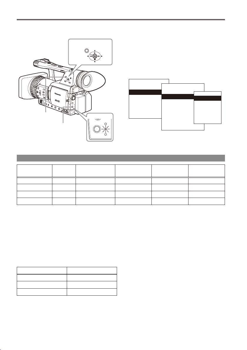
CAM mode (MCR)
Lights green:
Data can be saved onto the cards or loaded
from them.
Blinks green (slow):
No available space on card, card is writeprotected
Lights orange:
Slot that is the object of recording
Blinks orange:
Data is now being accessed.
Blinks orange (fast):
A card is now being recognized.
Both lamps blink orange:
Ejection of card during access
Off:
Cards have not been inserted or formatted.
Insertion of incompatible card.
PC mode (USB DEVICE)
Blinks orange: Data is now being accessed.
Off: A status other than access underway.
PC mode (1394 DEVICE)
Blinks orange: Connected
Off: Not connected
P2 card access lamp
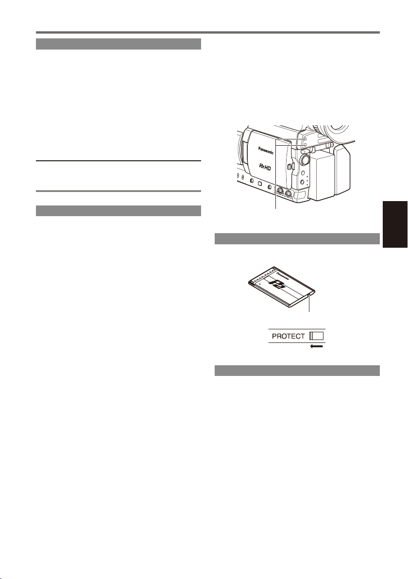
Protecting against a possible erasure
Switch the write-protect switch of the P2 card to
[PROTECT].
Write-protect switch
Formatting P2 cards
1 Set the POWER switch to ON. (Page 18)
2 Press the mode button and set it to MCR
mode (the MCR lamp lights).
Thumbnails are displayed.
•
(Continued on the next page)
Shooting
25
Page 26
MENU
PUSH-SET
SLOT SEL
MODE
CAM
MCR
PC
THUMBNAIL
OPERATION
PROPERTY
META DATA
EXIT
DELETE
FORMAT
REPAIR CLIP
RE-CONNECTION
EXCH.THUMBNAIL
EXIT
SLOT1
SLOT2
SD CARD
EXIT
Basic shooting operations (continued)
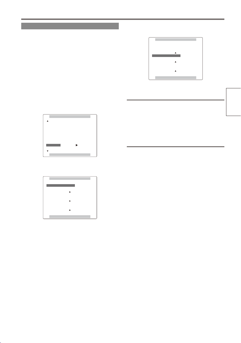
3 Press the MENU button.
For menu operation (Page 93)
•
Operation lever
4 On the menu, select OPERATION and then
FORMAT. (Page 67)
A screen such as the one shown below
•
appears. Select the number of the slot
into which you inserted the P2 card to
be formatted. Select EXIT to cancel the
formatting.
When you press the MENU button, the menu
•
display disappears.
MENU button
Mode button
Mode lamp
5 Select YES on the conrmation screen.
The selected P2 card is formatted.
•
Recording times
Card model Capacity
AJ-P2C004HG 4 GB approx. 16 min. approx. 8 min. approx. 4 min. approx. 8 min.
AJ-P2C008HG 8 GB approx. 32 min. approx. 16 min. approx. 8 min. approx. 16 min.
AJ-P2C016RG 16 GB approx. 64 min. approx. 32 min. approx. 16 min. approx. 32 min.
AJ-P2C032RG 32 GB approx. 128 min. approx. 64 min. approx. 32 min. approx. 64 min.
The AJ-P2C002SG (2 GB) card cannot be used.
•
The displayed available space includes the management area, and so the space available for recording is
•
DVCPRO/DV 2-
channel audio
smaller than this.
Concerning the division of clips recorded on P2 cards
•
When using a P2 card of at least 8 GB in this camera, if the continuous recording time for a single
session exceeds the time shown in the following table, recording will be automatically resumed as a
different clip. When performing a thumbnail operation (display, delete, restore, copy, etc.) on clips using
P2 cards, you can operate them as a single clip. When you are using non-linear editing software and a
PC, for example, the clips are displayed individually.
Recording Format Recording times *1 The 720P/25PN formats are not included in the
DVCPRO HD*1 approx. 5 min.
DVCPRO50 approx. 10 min.
DVCPRO/DV approx. 20 min.
DVCPRO50 4-
channel audio
DVCPRO HD*1
DVCPRO HD recording format.
DVCPRO HD
720P/25PN
When using any other types of cards, the driver installed in the camera-recorder may need to be updated.
•
•
26
(Page 118)
For the latest information not available in the Operating Instructions, visit the P2 Support Desk at the
following Web sites.
https://eww.pavc.panasonic.co.jp/pro-av/
Page 27
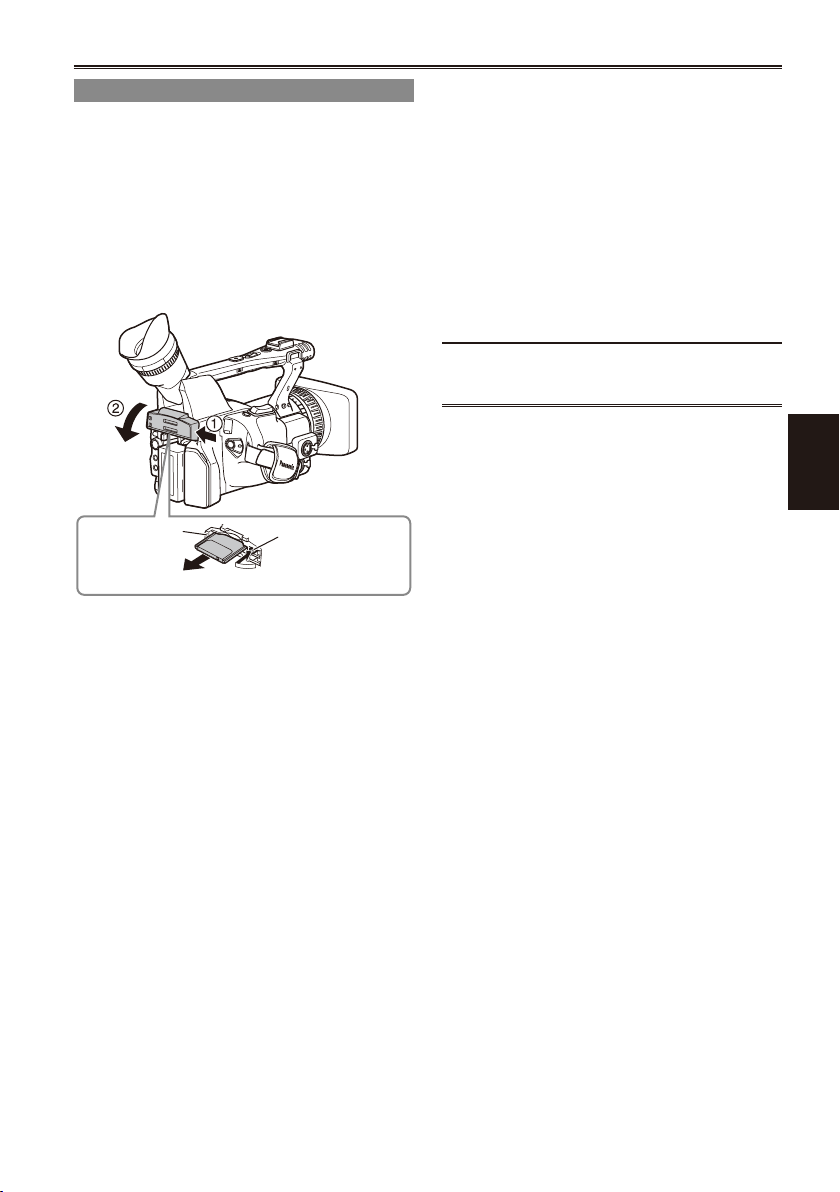
Remove the P2 card
4
3
1 Lift up the viewnder, press the side of the
card slot cover (A), and slide the cover (B)
to open it.
2 Check that the P2 card access lamp is not
blinking orange.
3 Raise the P2 card eject button and press it.
4 Remove the P2 card.
During playback, a P2 card inserted into the
•
empty slot will not be recognized and the P2
card access lamp will not light. When playback is
completed, the P2 card recognition will begin.
You can use ACCESS LED on the OTHER
•
FUNCTIONS screen to set the P2 card access
lamps so that they will always be off. In this case,
either turn off the power or wait until enough time
has passed after inserting the cards or stopping
operation before ejecting the cards.
If a P2 card is ejected while thumbnails are
•
displayed, the thumbnail screen is released.
Cautions in using P2 cards
Before using a P2 card, be sure to format it with
a P2 device.
Shooting
P2 card
access lamp
Do not eject the P2 card or turn the power off
•
under the following circumstances, since doing
so may cause a malfunction in the card:
1) While the orange P2 card access lamp is
blinking after the card is inserted (and until it
stops blinking).
2) During recording, during the recording nish
process, or while the access lamp is blinking.
If a P2 card is ejected during formatting or while
•
its data is being accessed, “TURN POWER
OFF” appears in the viewnder, and a warning is
indicated by the tally lamp. If this happens, turn
the power off and back on again.
When a card is ejected during formatting:
•
Format the card again.
When a card is ejected while its data is being
•
accessed:
The clips may be thrown out of order.
(Page 56) Check the clips and repair them.
(For details on repairing clips, see Page 67.)
Immediately after pre-recording, a P2
•
card inserted into an empty slot will not be
immediately recognized.
P2 card eject
button
27
Page 28
Using SD/SDHC memory cards
2
THUMBNAIL
OPERATION
PROPERTY
META DATA
EXIT
DELETE
FORMAT
REPAIR CLIP
RE-CONNECTION
EXCH.THUMBNAIL
EXIT
SLOT1
SLOT2
SD CARD
EXIT
You can use SD and SDHC memory cards (the
term “SD memory card” is used for both hereafter)
to save and load SCENE les and USER les, and
to upload clip meta data. (Page 54)
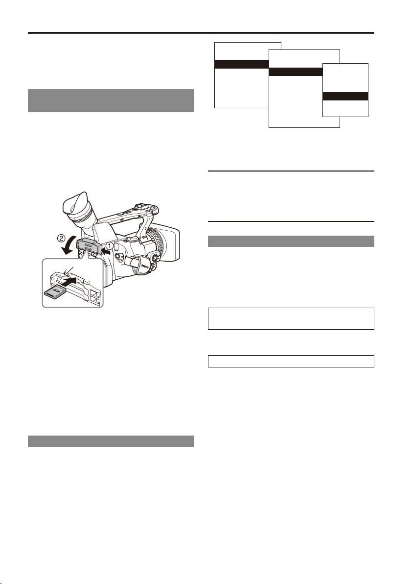
Installing and removing the SD memory card
Installation
1 Lift up the viewnder, press the side of the
card slot cover (A), and slide the cover (B)
to open it.
2 Insert the card while making sure it is
oriented in the proper direction.
Access lamp
3 Close the card slot cover.
Removal
1 Open the card slot cover, and check that
the access lamp is not lit.
2 Press the card further into the unit, grasp
the card, and then remove.
3 Close the card slot cover.
Formatting SD memory card
1 Set the POWER switch to ON. (Page 18)
2 Press the mode button and set it to MCR
mode (the MCR lamp lights).
3 Press the MENU button.
4 On the menu, select OPERATION, FORMAT
28
and then SD CARD. (Page 67)
Select EXIT to cancel the formatting.•
5 Select YES on the conrmation screen.
The selected SD memory card is formatted.
•
You can also format from the SD CARD
•
FORMAT option on the CARD FUNCTIONS
screen. (Page 109)
With SDHC cards, 32 KB of capacity will have
•
been used.
Cautions in using SD memory cards
SD memory cards used with the AG-HPX172EN
•
should conform to SD or SDHC standards. Be
sure to format cards using the AG-HPX172EN.
SD memory cards with the following capacity can
be used for the AG-HPX172EN.
SD (from 8 MB to 2 GB):
8 MB 16 MB 32 MB 64 MB 128 MB
256 MB 512 MB 1 GB 2 GB
SDHC (4 GB to 16 GB):
4 GB 8 GB 16 GB
For the latest information not available in the
Operating Instructions, visit the P2 Support Desk
at the following Web sites.
https://eww.pavc.panasonic.co.jp/pro-av/
SD memory cards must not be used or stored in
•
an environment where they may be Exposed to
high temperatures/humidities;
Exposed to water droplets; or
Electrically charged.
Be sure always close the cover when using an
•
SD memory card.
See also “Checkpoints for using memory cards”
•
on Page 122.
Page 29
Using the zoom function
OSD
COUNTER
RESET TITLE
STILL ADV
PAUSE
STILL ADV
INDEX
SELECT
STORE
OFF/ON
P.B.DIGITAL
VAR.
SEARCH
VOL+
-
PB.
ZOOM
MENU
SET
ITEM
STOP INDEX
MULTI/
P-IN-P
REC A.DUB
PLAY/REW FF/
ZOOM
DATE/
TIME
PHOTO
SHOT
START/
STOP
MANUAL
ZOOM
SERVO
This camera has a 13 x optical zoom function.
Zoom with the zoom button or the zoom ring.
Zoom button
Set the ZOOM switch to SERVO so that you can
use the motor-driven zoom.
T : Zoom in
W : Zoom out
Gently press the zoom button on the grip to zoom
slowly, rmly press to zoom faster.
You can change the zoom speed on the handle
zoom button by selecting one of three speeds with
the HANDLE ZOOM switch.
Set the HANDLE ZOOM switch speeds by going
to the setup menus, SW MODE screen HANDLE
ZOOM (Page 100).
HANDLE ZOOM switch
Handle zoom button
Zoom button
Zoom ring
Set the ZOOM switch to MANUAL so that you can
use the zoom ring.
You cannot use the zoom ring if the ZOOM switch
•
is set to SERVO. Trying to use it could damage
the camera.
Zoom ring
On the remote control
Press ZOOM/VOL to zoom with the motor drive.
Zoom speed is xed at medium.
•
ZOOM/VOL button
Digital zoom function
Assign the D.ZOOM function to any of the USER
1 – 3 buttons to enable use of the digital zoom.
(Page 41)
Each press of the USER button to which D.ZOOM
is assigned switches the zoom ratio in the following
order: OFF (x1) " x2 " x5 " x10 " OFF (x1).
The viewnder and the LCD monitor indicate the
•
zoom ratio when a setting other than OFF (x1) is
selected.
Digital zoom is available only in the 1080i/50i
•
format.
Digital zoom is not available when OFF is
•
selected under DRS (Page 98) on the setting
menu SCENE FILE screen.
While using the zoom function, the slow shutter
•
is disabled. While using the slow shutter, you
cannot use the digital zoom function.
Digital zoom cannot be changed during
•
recording.
Shooting
29
Page 30
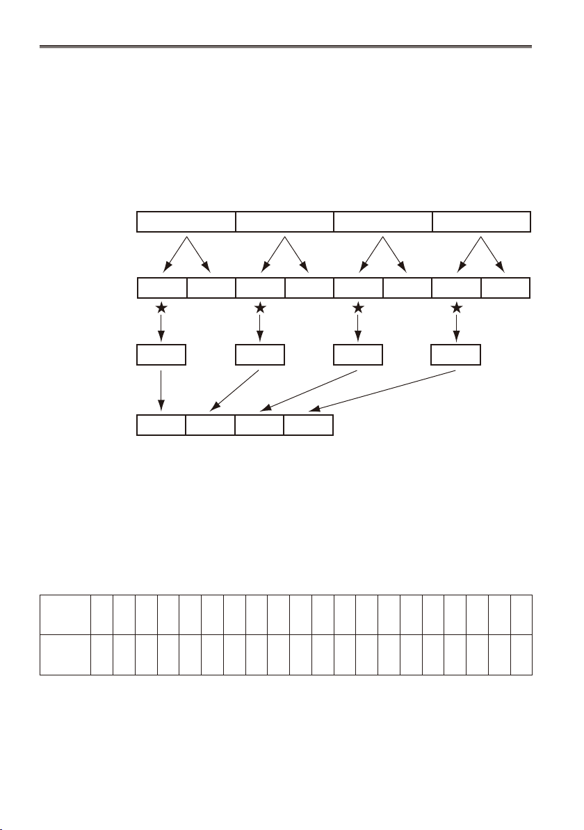
Variable frame rates (VFR)
1 2 3 4
1 1 2 2 33 4 4
1
1 2 3 4
2 3 4
By taking full advantage of the special characteristics of P2 cards, this unit provides frame skipping
(undercranking) recording and highspeed (overcranking) recording, which are actually movie techniques,
without the use of a frame rate converter. (Either the 25PN mode must be set for this.)
Since the camera-recorder records only the effective frames (native recording), recording is possible for 2
times as long compared with recording in the 25P or 50P mode (standard recording).
25PN mode:
The camera-recorder shoots in the 25 fps native mode. The video signals delivering images at a rate of
25 fps are recorded in 25 frames. The signals are recorded only in the effective frames so recording is
possible for 2 times as long.
Camera-Recorder
25P
25PN
«: effective frame
Before VFR shooting, you must set the recording frame rate and recording format ahead of time.
•
You cannot change the frame rates while recording.
•
VFR shooting is possible only in progressive-shooting mode with 720 vertical lines.
•
You can select any of 20 recording frame rates ranging from 12 frames per second (fps) to 50 fps.
The list of formats that allow recording by the camera-recorder (Page 123).
There may be slight discrepancies between the recording frame rate displayed and the frame rate at which
the images are actually recorded. Refer to the table below.
Indicated
recording
frame rate
Actual
recording
frame rate
50 48 45 42 37 34 32 30 28 27 26 25 24 23 22 21 20 18 15 12
50.00 48.08 45.00 41.67 36.76 34.09 32.14 29.76 28.13 27.17 26.04 25.00 24.04 23.15 22.06 20.83 19.74 17.86 15.00 12.50
30
Page 31

Native recording
Standard recording
1 Using the REC FORMAT function
(Page 103) on the RECORDING SETUP
screen, select 720P/25PN as the recording
format.
2 Select the appropriate scene le using the
SCENE FILE dial.
If necessary, before doing this, perform the
camera settings from the setting menu, and
register the scene le. (Page 52)
3 Using the OPERATION TYPE function
(Page 97) on the SCENE FILE screen, select
FILM CAM, and set the desired recording
frame rate using the FRAME RATE function
(Page 97).
4 Press the START/STOP button to start or
stop native recording in VFR mode.
No signals are output from the 1394 terminal
•
during recording or recording standby in the
native mode.
Sound is not recorded. However, sound will
•
be recorded when the same frame rate is
used for both recording and playback.
When a recorded clip lasting a long time
•
is to be played back and imported using
a nonlinear editing system that supports
Varicams, the UB MODE option on the
RECORDING SETUP screen must be set to
FRM.RATE.
If the effective frame information is to be
•
carried over when recording onto this
camerarecorder from a nonlinear editing
system that supports Varicams, the 1394 UB
REGEN option on the RECORDING SETUP
screen must be set to ON.
After editing, materials are output from the
•
nonlinear editing system in 1080i/25P or
720P/50P (25P over 50P) format.
1 Using the REC FORMAT function
(Page 103) on the RECORDING SETUP
screen, select 720P/50P or 720P/25P as the
recording format.
2 Select the appropriate scene le using the
SCENE FILE dial.
If necessary, before doing this, perform the
camera settings from the setting menu, and
register the scene le. (Page 52)
3 Using the OPERATION TYPE function
(Page 97) on the SCENE FILE screen, select
FILM CAM, and set the desired recording
frame rate using the FRAME RATE function
(Page 97).
When 720P/25P has been selected as the
recording format, the following displays appear
depending on the setting which has been
selected for the FRAME RATE item on the
SCENE FILE screen.
1) PULL DOWN information displayed in
PROPERTY-CLIP PROPERTY-VIDEO
With the default setting: 2:2
With any other settings: other
2) Format information in the bottom left of the
screen when thumbnails are displayed
With the default setting: 720P/25P
With any other settings: 720P/50P
(The “default” setting is 25FRAME if the
frame rate of the recording format is 25P).
4 Press the START/STOP button to start or
stop standard recording in VFR mode.
Sound is recorded.
•
In the case of a nonlinear editing system that
•
supports Varicams equipped with an effective
frame extraction function, you can upload even
undercrank or overcrank shooting materials as
is. (The UB MODE option on the RECORDING
SETUP screen must be set to FRM.RATE.)
After editing, materials are output from
•
the nonlinear editing system in 1080i/25P
720P/50P (25P over 50P) format.
The 25P format is used for 2:2 pull-down
•
recording.
Shooting
31
Page 32

Variable frame rates (VFR) (continued)
Using variable frame rates (VFR)
Standard speed shooting for making
commercials and dramas
When producing commercials and dramas to be
shown on a TV screen, as in the case of HDTV/
SDTV and other broadcasts, a frame rate of 25 fps
(frames per second) is the norm (1x speed).
If you use the settings below, the same kind of
playback as when the programs are broadcast can
be obtained. Commercials and music clips will be
recorded with a high lm-like picture quality while
the number of frames is also ideally suited to TV
broadcasts.
Recording format
(REC FORMAT)
720P/25P
(2:2 pull-down)
720P/25PN
(native recording)
Recording frame rate
(FRAME RATE)
25 fps*
Undercrank shooting
This way of shooting provides quick motion effects
used to present such scenes as the movement of
clouds, someone standing among crowd of people,
and moves made by martial artists. If, for instance,
you have shot scenes using the 25P recording
format for specifying the playback frames, you can
double the speed of the quick motion effects by
setting the VFR recording frame rate to 12 fps.
Recording format
(REC FORMAT)
720P/25P, 720P/25PN Set to 24 fps or lower.*
In the case of the 720P/25P format, the quick
•
motion effect can be obtained by using a
nonlinear editing system to process what has
been recorded.
Recording frame rate
(FRAME RATE)
Overcrank shooting
This way of shooting provides slow motion effects
used to show car chases as well as action scenes,
climax scenes and other dramatic presentations.
If, for instance, you have shot scenes using the
25P recording format for specifying the playback
frames, you can obtain slow motion effects with the
speed halved by setting the recording frame rate to
50 fps. Images in the 720P progressive format will
create smoothly owing slow motion sequences
with a high picture quality.
Recording format
(REC FORMAT)
720P/25P, 720P/25PN Set to 26 fps or higher.*
In the case of the 720P/25P format, the slow
•
motion effect can be obtained by using a
nonlinear editing system to process what has
been recorded.
* You can select any of 20 recording frame rates
ranging from 12 frames per second (fps) to
50 fps. (Page 97)
Recording frame rate
(FRAME RATE)
32
Page 33

Shooting in 1080i/576i progressive mode
Ao Ae Bo Be Co Ce Do De Eo Ee F o F e Go Ge Ho He Io Ie Jo Je
A B C D E F G H I J
25P
50i
Selecting 1080i/25P or 576i/25P in the REC
FORMAT option (Page 103) of the setting menu
RECORDING SETUP screen enables shooting in
progressive mode.
25P mode:
Shoot 25 frames a second in the progressive
mode.
For output and recording, the 25-frame-
persecond signal is converted to 50-eld-per-
second interlace.
This mode gives you high quality images.
Note the following when shooting in
progressive mode.
You cannot have a gain of 18 dB.
•
Set the shutter speed to 1/50 (OFF) for best
•
results.
Shooting
33
Page 34

Shooting in manual mode
Set the unit to manual mode when manually
adjusting the focus, iris, gain and white balance.
Switching to manual mode
Slide the AUTO/MANUAL switch to MANUAL to
switch to the manual mode. ( A on the viewnder
and LCD go out).
AUTO/MANUAL switch
Manual focusing
Focus ring
PUSH AUTO button AUTO/MANUAL switch
FOCUS switch
FOCUS/IRIS switch
1 Use the AUTO/MANUAL switch to switch to
manual mode.
2 Use the FOCUS switch to choose how to
control focusing.
A (AUTO):
Auto focus mode
M (MANUAL):
Manual focus mode
Turn the focus ring by hand.
∞:
The camera rst focuses on innity, then it
switches to manual focus.
The FOCUS switch automatically moves
back to M (MANUAL) after you move it to ∞.
3 Use the FOCUS RING (FOCUS/IRIS) switch
to change the function assigned to the
focus ring.
FOCUS: Adjusts focus.
IRIS: Adjusts iris (aperture).
When setting the FOCUS switch to M, also
•
set the FOCUS RING (FOCUS/IRIS) switch to
FOCUS.
Temporarily switching to auto focus
Even if you have switched FOCUS to M (MANUAL)
the camera will focus automatically while you press
down PUSH AUTO.
Switching to manual focus assist mode
To change from the manual focus mode to the
manual focus assist mode, set MF ASSIST to ON
on the setting menu SW MODE screen.
You can make coarse adjustments to the focus
•
in manual focus assist mode by turning the focus
ring about half the amount you would turn it in
manual focus mode.
Fine adjustment is made automatically after you
•
operated the focus ring.
If the focus differs considerably form the manually
•
set focus, the focus may not be set correctly.
Automatic adjustment is not performed until you
•
operate the focus ring for the next time.
Auto focus may not work properly if there is
•
ickering.
Select a shutter speed suited to the ambient light.
(Page 48)
If the auto focus mode is set with any format
•
except 50i and 50P, controlling the focus will take
slightly longer than in the normal focus mode.
If you have set ON for the AF item on the setting
•
menu AUTO SW screen, auto focusing will occur
regardless of the position of the FOCUS switch
when the auto mode has been established.
(Page 103)
During macro shooting “AF”, “MF” or “MA” will be
•
displayed in a frame on the screen.
34
Page 35

Using focus assist
Pressing the FOCUS ASSIST button magnies
the center portion of the image or brings up a
frequency distribution graph at the top right of the
image to assist during manual focusing.
You can use the FOCUS ASSIST setting on
the SW MODE screen to change the viewnder
and LCD monitor displays that appear when the
FOCUS ASSIST button is pressed. (Page 102)
FOCUS ASSIST button
EXPANDED:
Doubles the size of the center of the image.
GRAPH:
Displays a frequency distribution graph at the top
right in the viewnder and LCD monitor.
Turn the focus ring on the lens to place the graph
further to the right.
Out of focus The white area moves
BOTH:
Magnies the center portion of the image and
displays the frequency distribution graph.
The image on the LCD monitor may differ slightly
•
from the image in the viewnder when the
FOCUS ASSIST button is used in EXPANDED
mode.
The EXPANDED mode is available during 1080i
•
and 720P HD mode recording and standby, but
dues not work in external input mode.
In the 576i SD format, only the GRAPH display is
•
available. When set to the EXPANDED mode, the
focus assist function does not work. Even when
the BOTH mode is set, only the GRAPH display
is available.
The FOCUS ASSIST button does not work when
•
the digital zoom function is used.
To return to the previous screen, press the FOCUS
ASSIST button again.
to the right as the image
comes into focus.
Iris adjustments
IRIS dial FOCUS RING (FOCUS/IRIS) switch
IRIS button
1 If the camera is in auto mode, use the
AUTO/MANUAL switch to switch to manual
mode. (Page 34)
2 Press the IRIS button to switch how to
adjust the aperture of lens.
AUTO IRIS: Adjust the iris automatically.
MANUAL IRIS: Adjust the iris manually.
3 Turn the IRIS dial to adjust the aperture of
lens when in the manual iris mode.
In the auto iris mode, the lens iris can be
corrected using this dial.
Set the direction of the IRIS DIAL and aperture
control in the setup menus, SW MODE screen,
IRIS DIAL. (Page 100)
If you have set ON under A.IRIS on the setting
menu AUTO SW screen, auto iris will be forcibly
selected when auto mode has been established.
(Page 102)
Setting the FOCUS RING (FOCUS/IRIS) switch
•
to IRIS allows you to set aperture using the
focus ring on the lens. Note that since the focus
ring now does not control focus adjustment, set
the FOCUS switch to A (AUTO) focus control.
(Page 34)
This unit’s iris F number when it is open is F1.6
at full WIDE and F3.0 at full TELEPHOTO.
The iris display in the viewnder or on the LCD
when the iris is open is OPEN at full WIDE and
F2.8 or OPEN at full TELEPHOTO.
Shooting
35
Page 36

Shooting in manual mode (continued)
Adjusting the gain
When the display is dark, increase the gain to
brighten the display.
GAIN switch
1 If the camera is in auto mode, use the
AUTO/MANUAL switch to switch to manual
mode. (Page 34)
2 Switch the gain with the GAIN switch.
L: Set here under normal conditions. (0 dB)
M: Increase the gain of the image amplier.
(The default value is 6 dB.)
H: Increase the gain of the image amplier.
(The default value is 12 dB.)
You can change the M and H gain values using the
MID GAIN and HIGH GAIN items on the setting
menu SW MODE screen. (Page 100)
In auto mode, auto gain is available regardless of
the GAIN switch setting when a setting other than
OFF is selected under AGC on the setting menu
AUTO SW screen. (Page 103)
When the recording frame rate is less than 23 fps
and when a slow shutter speed (1/12) has been
set, the gain is xed at 0 dB regardless of the GAIN
switch setting. (Pages 30 and 48)
Light intensity adjustments
Use the ND FILTER Switch to change the ND Filter
used (lter to change light intensity).
OFF: ND lter is not used.
1/4: Cuts light intensity by up to about 1/4.
1/16: Cuts light intensity by up to about 1/16.
1/64: Cuts light intensity by up to about 1/64.
ND FILTER switch
36
Page 37

Adjusting the white balance
In order to reproduce the white accurately, adjust
the ratio between the three RGB primary colors. If
the white balance is not adjusted properly, not only
will the white be reproduced poorly but the color
tones of the entire screen will also be downgraded.
When you are shooting in manual mode, readjust
the white balance whenever lighting conditions
change.
You can save adjustments and reselect them by
setting the WHITE BAL switch to A or B.
You can also use the preset values.
Use the settings to suit the shooting conditions.
WHITE BAL switch
AWB button
White balance adjustments
5 Press the AWB button.
Adjustment takes a few seconds.
•
(The following messages appear on the
screen.)
Message during adjustment
AWB Ach ACTIVE
Message after adjustment
AWB Ach OK
An error message appears on the screen when
white balance adjustment is not possible.
Message when adjustment cannot be done
AWB Ach NG
White balance cannot be adjusted if the Auto
•
Tracking White (ATW) function is working.
If you have set ON under ATW (Auto Tracking
White) on the setting menu AUTO SW screen,
ATW will be selected when auto mode has been
established regardless of the WHITE BAL switch
position. (Page 103)
Make the necessary adjustments if one of the
following error messages appears, then try
adjusting the white balance again.
Shooting
1 If the camera is in auto mode, use the
AUTO/MANUAL switch to switch to manual
mode. (Page 34)
2 Set the shutter speed. (Page 48)
3 Place a white pattern in a location with the
same lighting conditions and light source
as the subject, then zoom in and ll the
whole screen with white.
Something white (a white cloth or wall) near
the subject can be used instead.
Do not include bright spotlights in your shot.
•
4 Set the WHITE BAL switch to A or B
(whichever one you want to save the
adjustment in).
Error messages Adjustments
LOW LIGHT Increase light or increase
the gain.
LEVEL OVER Reduce light or decrease
the gain.
If the messages repeatedly appear even after
•
trying a number of times, consult your dealer.
37
Page 38

Shooting in manual mode (continued)
Using presets
Use this feature when you have no time to make
white balance adjustments.
1 If the camera is in auto mode, use the
AUTO/MANUAL switch to switch to manual
mode ( A on the viewnder and LCD goes
out).
2 Set the WHITE BAL switch to PRST.
The current white balance value appears.
White balance values 3200 K and 5600 K are
•
preset in the PRST position.
Guide to the preset values
P3.2K (3200 K): halogen light
P5.6K (5600 K): outdoors
3 Press the AWB button.
White balance switches between 3200 K and
5600 K.
Black balance adjustments
In order to reproduce the black accurately, adjust
the zero level of all three RGB primary colors. If the
black balance is not adjusted properly, not only will
the black be reproduced poorly but the color tones
of the entire screen will also be downgraded.
It is not normally necessary to adjust the black
balance. Adjust it when:
You use the camera for the rst time.
•
You use the camera after not using it for a long
•
time.
The ambient temperature changes greatly.
•
You switch to the normal (OFF) shutter speed or
•
to slow shutter.
You switch between the progressive and normal
•
(50i) modes.
You cannot adjust the black balance while you
•
are shooting.
Message during adjustment
ABB ACTIVE
Message after adjustment
ABB END
Hold down the AWB button to adjust the black
•
balance (available also when the ATW function
is used).
Auto Tracking White (ATW)
You can allocate the ATW feature to one of the
positions on the WHITE BAL switch (A, B, or
PRST). Allocate it by going to the setup menus,
SW MODE screen, ATW. (Page 100)
The ATW feature is set to work in the auto mode at
the time of shipping. (Page 103)
If you use the ATW feature whenever you are
shooting, the camera automatically adjusts the
white balance as you shoot.
The ATW feature automatically determines the
•
current shooting environment and adjusts the
white balance accordingly. Depending on the
environment, there may be some error in the
adjustment.
Use the procedure described on the preceding
page whenever you need more precise white
balance.
Do not block the white balance sensor when using
the ATW feature. ATW will not work if you do.
White balance sensor
Press the AWB button to automatically adjust the
white balance.
Press and hold the AWB button to adjust the black
balance.
As the white balance is adjusted rst when you
•
press the AWB button, make the necessary
preparations for this.
38
Page 39

ZEBRA 1 ZEBRA 2
OFF MARKER
BARS
CH1 SELECT
RESET/TC SET
REC
CH2 SELECT
AUDIO
INT(L)
INPUT1
INPUT2
SHUTTER
SPEES SELECT
INT(R)
INPUT2
INPUT1
MIC POWER+48V
ON
OFF
INPUT2
ON
OFF
LCD
ZEBRA
EVF DTL
OIS
WFM
COUNTER
99%
Shooting techniques for different targets
Low-angle shooting
Set the Recording enable/disable switch to ON
and use the START/STOP button on the handle to
make it easier to shoot from low angles.
Set the Recording enable/disable switch to OFF
•
to prevent inadvertent use of the START/STOP
button on the handle when this function is not
needed.
Recording enable/disable switch
START/STOP button
Self-portrait shooting
Images in the LCD when it is turned 180 degrees
for self-portrait shooting may appear unusual.
You can make them appear better by reversing
left and right. Go to the setup menus, DISPLAY
SETUP screen, SELF SHOOT, and select
MIRROR.
Shooting in mirror mode has no effect on what you
actually shoot and record.
Zebra pattern
Press the ZEBRA button in CAM mode to show the
zebra pattern or marker on the screen so you can
check the brightness of the subject.
Parts that may be whited out through over
exposure are shown as a zebra pattern.
Very bright
•
Reecting parts
•
You can remove most overexposed parts by
adjusting the iris and shutter speed in the manual
mode to remove the areas with zebra patterns.
The display changes as follows each time you
press the ZEBRA button.
In the setup menus, DISPLAY SETUP screen,
ZEBRA DETECT 1 and ZEBRA DETECT 2, set the
brightness for the zebra patterns. (Page 107)
The zebra pattern you have set appears as a
percentage on the display for about 2 seconds.
Marker
If you press the ZEBRA button again while the
zebra pattern is being displayed, a marker appears
in the center of the display (if you have set the
setup menu, DISPLAY SETUP, MARKER to ON).
The brightness of the areas near the screen center
can be checked as a percentage (0% to 99%).
“99%” appears if the percentage is over 99.
Shooting
Image level detection area
Marker
Image level
The normal display reappears if you press the
ZEBRA button again.
39
Page 40

Shooting techniques for different targets (continued)
Checking and displaying shooting status
DISP/MODE CHK button
When you hold down the DISP/MODE CHK
button during recording standby or recording, all
the information including the setting status of the
shooting functions and a list of functions allocated
to the USER buttons, will be displayed. When
you release the button, the normal display will be
restored.
When you push the DISP/MODE CHK button
during recording standby or recording, all the
information will be unshown. When you press the
button again, the normal display will be restored.
The information is retained even if you turn off the
unit’s power or switch to another operation mode.
To display property of the selected clip in MCR
mode, press the DISP/MODE CH button in the
thumbnail screen. Press the button again to return
to the thumbnail screen.
Changing the image size
When recording in 576i mode, you can change the
size (aspect ratio) of the images that you record.
Select the aspect ratio in the setup menus,
CAMERA SETUP screen, ASPECT CONV.
(Page 99)
For menu operation (Page 93)
•
SIDE CROP:
Recorded in the regular 4:3 aspect ratio.
The left and right edges of the image are cut.
LETTER BOX:
Recorded in the 16:9 aspect ratio.
Black bands are recorded at the top and bottom
of the image.
SQUEEZE:
The recorded images are squeezed horizontally
so that they are shown as 16:9 images on a
compatible wide-screen television.
If you have selected SQUEEZE, “SQU” appears
on the screen.
40
To change the aspect ratio display of the
viewnder and LCD
Select the aspect ratio in the setup menus,
DISPLAY SETUP screen, DISPLAY ASPECT.
(Page 108)
Page 41

Optical Image Stabilizer
BARS
CH1 SELECT
RESET/TC SET
REC
CH2 SELECT
AUDIO
INT(L)
INPUT1
INPUT2
SHUTTER
SPEES SELECT
INT(R)
INPUT2
INPUT1
MIC POWER+48V
ON
OFF
INPUT2
ON
OFF
LCD
ZEBRA
EVF DTL
OIS
WFM
COUNTER
Use the Optical Image Stabilizer (OIS) to reduce
the effects of camera shake when shooting by
hand.
Press the OIS button to turn the function on and
off.
appears on the screen when this function is on.
Turn the function off when using a tripod for more
natural images.
This function will not be as effective when the
•
vibration is severe or when tracking a moving
subject.
Using the USER buttons
You can allocate one of sixteen features to each of
the three USER buttons.
Use these buttons to change shooting settings
quickly or add effects to the images you are
shooting.
The following features are allocated to the buttons
at the time of shipping.
USER1: WHITEFADE
USER2: BACKLIGHT
USER3: TEXT MEMO
For details, see the setup menus, SW MODE
screen, USER1 to 3. (Page 101)
If you press a USER button to which one of the
following functions has been allocated and then
turn off the power, that button will revert to the
previous setting:
SPOTLIGHT, BACKLIGHT, ATW, ATW LOCK,
GAIN:18 dB, D.ZOOM
Shooting
Adding effects to images
Press the USER button you have allocated to the
BLACKFADE or WHITEFADE feature to add fading
effects to your images. The button’s function is
forcibly canceled during playback or REC CHECK
and also when thumbnails are displayed.
BLACKFADE:
Press and hold to fade out to black. Audio also
fades out. Fade-in starts when the button is
released.
WHITEFADE:
Press and hold to fade out to white. Audio also
fades out. Fade-in starts when the button is
released.
Backlight compensation
Press the USER button you have allocated to the
BACKLIGHT feature when shooting subjects lit
from the back.
BACK appears on the screen.
Backlight compensation adjusts the iris so the
subject doesn’t come out dark.
Press the same USER button to turn the feature
off.
Color bars
Press the BARS button in CAM mode to output a
color bar screen to a television or monitor so you
can adjust them.
Press the button again to turn the feature off.
A 1 kHz test tone is output in the color bar screen
when ON is selected under TEST TONE on the
setting menu AV IN/OUT SETUP screen.
The color bar can be recorded together with a
•
1 kHz test tone.
41
Page 42

PAGE/AUDIO MON/VAR
Shooting techniques for different targets (continued)
Waveform monitor function
Press the WFM button in CAM mode to display a
waveform of the image on the LCD monitor.
Pressing the WFM button once again closes the
waveform display.
WFM (Page 102) on the setting menu SW
•
MODE screen allows you to switch between the
waveform and vector display.
The viewnder does not show the waveform
•
display.
The waveform does not appear when the focus
•
assist function is used.
The waveform display cannot be recorded.
•
Adjusting the volume while shooting
Adjusting the volume
If you are monitoring the sound through
headphones while shooting, you can adjust the
volume with the PAGE/AUDIO MON/VAR button.
To adjust the recording level (Page 51)
•
Backup recording
If you have connected equipment to the 1394
terminal (Pages 76 and 77), you can make
automatic backup recordings of whatever you are
shooting.
In the setup menus, OTHER FUNCTIONS
•
screen, 1394 CONTROL and 1394 CMD SEL,
select how to control the equipment you have
connected. (Page 109)
Note the following when backup recording.
Menu settings are retained even if you turn
•
the power off. So if you use the camerarecorder with the settings for backup
recording still in effect, images on media in
any unit that connected may be overwritten.
After backup recording, check the menu item
settings before you operate the camerarecorder.
If you use another AG-HPX172EN as the
•
external unit for backup recording, select
“OFF” for 1394 CONTROL on the external
unit and set it to MCR mode.
Backup recording may not work properly if
•
you connect two or more external units.
Use a 1394 cable of 4.5 m or less for
•
connection.
Set the external unit up to receive 1394
•
signals before backup recording.
You can have a media in the external unit
•
start recording automatically when the media
in this unit is almost nished. Set 1394
CONTROL on the setting menu OTHER
FUNCTIONS screen (Page 109) to “CHAIN”.
Note that images are recorded even when
•
you perform a rec check.
You cannot perform backup recording when
•
the unit is set up for native recording.
Backup recording does not work in three
•
of the special recording modes: Interval
recording, One-shot recording and Loop
recording (Pages 45 – 47)
Backup recording does not work during direct
•
shooting (Page 65) in MCR mode.
42
Page 43

2-slot continuous recording
If you insert two P2 cards into the two card slots,
this function allows you to record continuously on
the two cards.
You can also record continuously on three or
more cards by replacing one card while data is
being recorded on the other. (Hot swap recording)
However, depending on when the P2 card is
inserted into an empty slot (immediately after prerecording, or before or after continuous recording
spanning two slots), there may be a delay in
recognizing the P2 card. We recommend inserting
the P2 card while there is at least one minute
remaining on the card that is recording.
The SLOT SEL button offers a one-touch
mechanism to select the slot whose card will be
recorded.
You cannot change slots while recording so do
•
this during recording standby.
Does not support hot swap playback.
•
Shot mark function
The marks attached to the thumbnails of clips
are called shot marks. On the thumbnail screen
monitor you can select only those clips with a shot
mark and display them or play them back.
During recording, when you press the USER button
to which the SHOT MARK function has been
allocated, MARK ON appears in the LCD monitor
or the viewnder, and a shot mark is set for the
thumbnail of the clip being recorded. If you press
the button again, the shot mark is released.
You can also set or release the shot marks by
performing the thumbnail operations for clips.
(Page 65)
However, note that you cannot set or release shot
marks during playback.
INVALID appears when you cannot set or release
•
shot marks.
When the video data of a single shoot using
•
hot swap recording is made up of multiple clips,
you cannot set or release shot marks unless all
the P2 cards that make up the video data are
inserted into the slots.
You cannot set or release shot marks during loop
•
recording.
Text memo recording
This function adds text memos at the video points
on the clip now being recorded or played back.
When you press the USER button to which the
TEXT MEMO function has been allocated, the text
memo will be recorded at that point. (Page 41)
On the thumbnail screen you can select only those
clips where text memos have been added, and
then either display those clips or play them back.
You can record up to a hundred text memos per
clip.
You will need the latest updated version of P2
Viewer to edit the text memos. (Page 121)
You cannot record text memos during interval
•
recording or one-shot recording.
INVALID appears when you cannot record text
•
memos.
Time stamp function
Use the time stamp function to record date and
time of shooting on the video.
Select ON under TIME STAMP on the setting menu
RECORDING SETUP screen.
“ R ” prexes the date and time display in the
viewnder and the LCD monitor when the time
stamp function is on.
“ R ” is not recorded on the video.
•
The size and location of the date and time
•
characters will vary with the recording format.
The data recorded depends on the DATE/TIME
•
setting on the setting menu DISPLAY SETUP
screen. No data is recorded when OFF is
selected.
Superimposed characters are output only during
•
1394 output.
Shooting
43
Page 44

Shooting techniques for different targets (continued)
LAST CLIP DELETE function
Assign LAST CLIP to any of the USER 1 – 3
buttons to enable a convenient way to delete the
last recorded clip.
Pressing the USER button to which LAST CLIP
was assigned displays a YES/NO conrmation
dialog on the screen.
Select YES, and the last recorded clip is deleted
and “LAST CLIP DELETE OK” is displayed.
Select NO to cancel clip deletion.
•
Clips cannot be deleted when a switch has been
•
made to the MCR or PC mode or the recording
format has been changed after completing a
recording. Then it will not be possible to delete
the clip by turning the power off and turning it
back on.
This button cannot be used to delete clips when
•
a P2 card (one of two inserted cards) has been
removed and reinserted after recording, nor can
it be used to delete clips on a write-protected P2
card.
In hot swap recording, the clip delete function is
•
not available unless all the P2 cards containing
data shot in one recording operation are inserted.
The YES/NO conrmation dialog does not appear
•
when the clip delete function is not available.
44
Page 45

Using the special recording functions
Making the settings in the RECORDING SETUP screen (Page 103) enables special recording functions
such as Pre-recording, Interval Recording, One Shot Recording, and Loop Recording.
These special recording functions can be used only when the settings below are established.
OPERATION TYPE item (Page 97): VIDEO CAM
•
Recording format: 1080i/50i, 720P/50P, 576i/50i, 1080i/25P, 720P/25P or 576i/25P
•
Pre-recording (PRE REC)
This function is used to record pictures and sound
starting at a xed time (approx. 3 seconds for HD
recording or approx. 7 seconds for 576i recording)
before the time when the actual recording has
been set to start.
Recording start operation Recording stop operation
(Time)
Actual recording
Pre-recording time
time
1 Check that the settings given above have
been established for the OPERATION TYPE
item and recording format.
2 Select ON under PREREC MODE.
(Page 103)
For menu operations (Page 93)
•
3 Press the START/STOP button.
Pre-recording starts.
In the following cases, the pre-recording
•
function will be canceled, and recording will
be initiated from the respective operation
points.
· When 1394 input recording is initiated
· When the unit is transferred from the
playback mode to the recording mode
· When interval recording is initiated
· When one-shot recording is initiated
· When loop recording is initiated
Immediately after switching from the MCR
•
mode to CAM mode, immediately after
turning on the camera-recorder’s power or
immediately after changing the PRE-REC
option setting, it may not be possible to
record the images and sound before the time
mentioned on the previous page has elapsed
even if the recording has been started
straight away.
Interval recording (INTERVAL REC)
With this function, the unit continuously
records frames (1/25 sec.) one at a time with
an interval.
The interval can be set with INTERVAL TIME item.
One-frame
recording
Time set as
INTERVAL TIME
One-frame
recording
Time set as
INTERVAL TIME
One-frame
recording
(Time)
1 Check that the settings given above have
been established for the OPERATION TYPE
item and recording format.
2 Select INTERVAL under REC FUNCTION.
(Page 103)
For menu operations (Page 93)
•
3 Set the time INTERVAL TIME. (Page 103)
4 Press the START/STOP button.
The unit starts INTERVAL REC operation.
To stop operation, push the Operation lever
•
in the g direction.
To release the function, either turn off the
•
unit’s power or select NORMAL under REC
FUNCTION.
The following displays will appear on the left
•
of the operation status display.
While recording is underway: I-REC lights up.
In temporary standby: I-PAUSE lights up.
While recording is stopped: The “I-” of I-
PAUSE ashes.
However, if the duration selected in step 3 is
less than 2 seconds, I-REC will ash while
recording is underway in accordance with the
set time.
The pre-recording function does not work.
•
No sound is recorded.
•
Shooting
(Continued on the next page)
45
Page 46

Using the special recording functions (continued)
All data recorded while this mode is active
•
will be contained in one le.
No guarantees are made for the 1394 output
•
images.
Operation is not possible even if only one of
•
the inserted cards is DIR ENTRY NG CARD.
(Page 90)
After interval recording has started, a
•
recordable P2 card cannot be used even if it
is inserted into an empty slot.
The slots for recording in this mode are
•
indicated by the orange P2 card access
lamps.
The slots for recording P2 cards that are
inserted after starting recording are indicated
by the green P2 card access lamps.
Text memos cannot be added.
•
One-shot recording (ONE-SHOT REC)
This function records a single shot at each unit of
time which has been set.
1 Check that the settings given on Page 45
have been established for the OPERATION
TYPE item and recording format.
2 Select ONE SHOT under REC FUNCTION.
(Page 103)
For menu operations (Page 93)
•
3 Set the recording time using ONE-SHOT
TIME. (Page 103)
4 Press the START/STOP button.
Recording continues for the duration set in
step 2 and then goes on standby.
To stop operation, push the Operation lever in
the g direction.
To release standby, either turn off the unit’s
power or select NORMAL under REC
FUNCTION.
The following displays will appear on the left
•
of the operation status display.
While recording is underway: I-REC lights up.
In temporary standby: I-PAUSE lights up.
While recording is stopped: The “I-” of
I-PAUSE ashes.
The pre-recording function does not work.
•
No sound is recorded.
•
All data recorded while this mode is active
•
will be contained in one le.
No guarantees are made for the 1394 output
•
images.
•
•
•
•
•
•
Loop recording (LOOP REC)
This function is used to record rst on one card
and then on the next when you have inserted two
P2 cards into the card slots. If there is not enough
free memory remaining on the second card,
recording returns to the rst card whose data will
then be overwritten. When data is overwritten, the
saved clips are deleted, and then the new clips are
recorded in their place. (Clip deletion is performed
approximately 30 seconds before the overwrite.)
1 Check that the settings given on Page 45
have been established for the OPERATION
TYPE item and recording format.
2 Select LOOP under REC FUNCTION.
(Page 103)
•
3 Press the START/STOP button.
Recording starts.
To stop operation, press the START/STOP
button.
To release the function, either turn off the
unit’s power or select NORMAL under REC
FUNCTION.
•
46
Operation is not possible even if only one of
the inserted cards is DIR ENTRY NG CARD.
(Page 90)
When continuous one-shot recording
is performed, there may be delays in
acknowledging the recording operation.
After one-shot recording has started, a
recordable P2 card cannot be used even if it
is inserted into an empty slot.
The slots for recording in this mode are
indicated by the orange P2 card access
lamps.
The slots for recording P2 cards that are
inserted after starting recording are indicated
by the green P2 card access lamps.
Text memos cannot be added.
For menu operations (Page 93)
The following displays will appear on the left
of the operation status display.
While recording is underway: L-REC lights
up.
While recording is stopped: L-PAUSE lights
up.
Insufcient memory space: LACK L- ashes.
Page 47

Use two P2 cards each with a recording
•
capacity of more than one minute. Recording
stops when either card is ejected.
This function does not work during 1394
•
input recording.
The pre-recording function does not work.
•
Operation is not possible even if only one of
•
the inserted cards is DIR ENTRY NG CARD.
(Page 90)
Stopping may take some time.
•
The following operations are not
•
acknowledged until the P2 card access
lamps change from blinking to fully lit up.
The slots for recording in this mode are
•
indicated by the orange P2 card access
lamps.
Text memos cannot be added.
•
Shooting
47
Page 48

BARS
CH1 SELECT
RESET/TC SET
REC
CH2 SELECT
AUDIO
INT(L)
INPUT1
INPUT2
SHUTTER
SPEES SELECT
INT(R)
INPUT2
INPUT1
MIC POWER+48V
ON
OFF
INPUT2
ON
OFF
LCD
ZEBRA
EVF DTL
OIS
WFM
COUNTER
1/60.0
PUSH STILL
Adjusting the shutter speed
SHUTTER button
SPEED SELECT button
1 Press the SHUTTER button.
Each time you press the SHUTTER button, the
shutter speed switches between normal (OFF)
and the speed you selected with the SPEED
SELECT button.
2 After you have pressed the SHUTTER
button, press SPEED SELECT to select the
shutter speed.
The shutter speed changes as follows each
time you press SPEED SELECT + (The
order is reversed for the SHUTTER SELECT
- button.)
Remember that the faster the shutter speed,
•
the lower the sensitivity.
If iris is set to auto, then it will open wider
•
with higher shutter speeds and thereby
reduce focal depth.
It will take longer to focus when the
•
shutter speed has been reduced so it is
recommended that the unit be secured to a
tripod, etc. for use.
The current shutter speed appears on the
viewnder and LCD screens unless you have
selected OFF in OTHER DISPLAY in the DISPLAY
SETUP screen of the setup menus.
It is not displayed if you have set the shutter speed
to normal (OFF).
With articial lighting and especially uorescent
lights and mercury-vapor lamps, the luminance
changes in synchronization with the power
line frequency. When this frequency is 50 Hz,
mutual interference will occur between the
camerarecorder’s vertical sync frequency (approx.
60 Hz) and the lighting frequency (50 Hz). This
means that the white balance may change
periodically.
Before shooting in areas with articial lighting or
adjusting the white balance, set the shutter speed
as follows.
Progressive
mode
Shutter speed
50 Hz 60 Hz
OFF (50i) 1/60 OFF (1/50)
25P/25PN OFF (1/50) 1/60
The gain is xed at 0 dB with a shutter speed of
•
1/12.
With the 1080i/50i, 720P/50P and 576i/50i formats
Standard (Off) 1/50
SYNCRO SCAN "1/12 "1/25 "1/60 "1/120
1/2000 "1/1000 "1/500 "1/250
With the 1080i/25P, 720P/25P, 576i/25P and 720P/25PN formats
Standard (Off) 1/50
SYNCRO SCAN "1/12 "1/25 "1/60
1/1000 "1/500 "1/250 "1/120
* Bold and underlines indicate formats that can be selected only when VIDEO COM is selected under
OPERATION TYPE, and OFF is selected under DRS in the SCENE FILE screen of the setup menus.
48
Page 49

Synchro scan
Set the shutter speed of the synchro scan (used
when shooting a television or computer monitor) in
the setup menus, SCENE FILE screen, SYNCRO
SCAN. (Page 97)
Adjust the shutter speed to match the frequency
•
of the television or computer monitor to minimize
the horizontal noise that appears when shooting
such subjects.
When the OPERATION TYPE option in the
•
SCENE FILE screen (Page 97) is set to FILM
CAM, the shutter opening angle can be adjusted
from 10° to 360° in 0.5° steps.
Example: When the recording frame rate is set to
25 fps and the exposure time is halved, 1/25 ÷2 =
1/50 = 180° (1/25 = 360°)
In the default setting (180°), this becomes 1/2 of
the exposure time. If it were 90°, it would be 1/4,
and if it were 45°, it would be 1/8 of the exposure
time.
(Shutter opening angle: This is equivalent to the
shutter speed of a lm camera, and a wider angle
results in a longer exposure to light.)
If the shutter speed is displayed in blue
•
characters followed by (1/50), you cannot change
the shutter speed in the blue characters while the
current recording format is used. The speed is
xed at (1/50).
Shooting
You can change the progressive mode in
the setup menu with REC FORMAT in the
RECORDING SETUP screen. (Page 103)
49
Page 50

BARS
CH1 SELECT
RESET/TC SET
REC
CH2 SELECT
AUDIO
INT(L)
INPUT1
INPUT2
SHUTTER
SPEES SELECT
INT(R)
INPUT2
INPUT1
MIC POWER+48V
ON
OFF
INPUT2
ON
OFF
LCD
ZEBRA
EVF DTL
OIS
WFM
COUNTER
Switching Audio Input
During shooting, you can record up to four
channels of sound. You can also switch the input
sound to be recorded on each of the channels to
the built-in microphones, external microphones or
audio equipment connected to camera. (See table
below)
CH1* CH2** CH3 CH4
INT(L): Built-in
microphone L
INT(L): Built-in
microphone L
INPUT1
INPUT1 INPUT2
INPUT2 INPUT2
INPUT2
INT(R): Built-in
microphone R
INPUT2 INPUT1
INT(R): Built-in
microphone R
INT(R): Built-in
microphone R
INT(L): Built-in
microphone L
INT(L): Built-in
microphone L
INT(L): Built-in
microphone L
INT(L): Built-in
microphone L
INPUT1 INPUT2
INT(R): Built-in
microphone R
INPUT2
INT(R): Built-in
microphone R
INT(R): Built-in
microphone R
INPUT2
* The input sound to be recorded onto CH1 can be
switched using the CH1 SELECT switch.
** The input sound to be recorded onto CH2 can be
switched using the CH2 SELECT switch.
The CH3 and CH4 input sound is determined
•
automatically by what was selected using the
CH1 SELECT switch and CH2 SELECT switch.
However, the following restrictions apply depending
on the media and format used. (Page 123,
Recording format)
When the DVCPRO HD or DVCPRO50 format is
used:
The recording mode is xed at 4-channel
recording.
When the DVCPRO25 or DV format is used:
Either 2 or 4 channels can be selected using 25M
REC CH SEL on the setting menu RECORDING
SETUP screen.
INPUT 1/2 (MIC
CH2 SELECT switch
CH1 SELECT switch
POWER +48V)
Switch
Using the built-in microphone
1 Switch the CH1 SELECT switch to INT (L).
Audio from the built-in microphone Lch is
•
recorded to audio channel 1.
2 Switch the CH2 SELECT switch to INT (R).
Audio from the built-in microphone Rch is
•
recorded to audio channel 2.
Using another microphone and audio equipment
1 Connect an external microphone or audio
equipment to the INPUT 1/2 (XLR 3-pin)
terminal. (Page 75)
2 Use the INPUT 1/2 switch to switch the
audio input.
LINE: (audio equipment is connected)
Input level is 0 dBu.
MIC: (another microphone is connected)
Input level is -50 dBu.
You can change the input level to -60 dBu
in the setup menus, RECORDING SETUP
screen MIC GAIN 1 and MIC GAIN 2
(Pages 103 and 104). Be aware that
sensitivity will be higher if you choose -60
dBu so you will record more noise.
3 When using the phantom microphone,
set the INPUT 1/2 (MIC POWER +48V) switch
to ON.
ON: (When using the phantom microphone)
+48V power supply to INPUT 1/2 terminal.
OFF: (When a phantom microphone is not
connected)
No power supply for INPUT 1/2 terminal.
The battery will discharge faster if you use a
•
phantom microphone.
Set to OFF if you connect equipment not
•
compatible with +48V. You can damage such
equipment if you leave the setting at ON.
INPUT 1/2 switches
50
4 Use the CH1 SELECT switch to select
the input signal to be recorded to audio
channel 1.
INT (L):
Audio from the built-in microphone Lch is
recorded to audio channel 1.
INPUT 1:
Audio from a device connected to INPUT 1
terminal is recorded to channel 1.
Page 51

INPUT 2:
1
C
H
-18 dB -12 dB 0 dB
2
C
H
1
C
H
2
C
H
1
C
H
2
C
H
1
C
H
2
C
H
Audio from a device connected to INPUT 2
terminal is recorded to channel 1.
5 Use the CH2 SELECT switch to select
the input signal to be recorded to audio
channel 2.
INT (R):
Audio from the built-in microphone Rch is
recorded to audio channel 2.
INPUT 2:
Audio from a device connected to INPUT 2
terminal is recorded to channel 2.
When inputting the microphone signal to
•
channels 1 and 2, connect the microphone to
INPUT 2 and switch both CH1 SELECT and
CH2 SELECT to INPUT 2.
Adjusting the recording level
AUDIO LEVEL knob
Use the AUDIO LEVEL knob to adjust the
recording level of the built-in microphone or of
audio signals input through the INPUT 1/2 (XLR
3-pin) terminal.
To adjust the volume of the sound for monitoring.
(Page 42)
To adjust the recording level of the audio signals,
turn the AUDIO LEVEL knob while referring
to the audio level meter at the bottom left of
the viewnder and LCD monitor, regardless of
the MIC ALC option setting (Page 103) on the
RECORDING SETUP screen of the setting menu.
Shooting
The CH1 and CH2 characters are highlighted
•
(they will appear in black text) when INT MIC on
the AV IN/OUT SETUP screen is set to OFF.
INT MIC ON INT MIC OFF
Check the recording level prior to shooting.
The recording level is set higher than for
•
Panasonic’s broadcast-use camera recorders
(AJ series).
51
Page 52

SCENE FILE F1:
PUSH MENU TO RETURN
MATRIX NORM1
OFF
THIN
–– ––
NORMAL
–– ––
–– ––
MIRROR
SKIN TONE DTL
LCD SET
EVF SET
V DETAIL FREQ
NAME EDIT
LCD BACKLIGHT
SELF SHOOT
SCENE FILE F1:
PUSH MENU TO RETURN
MATRIX NORM1
OFF
THIN
–– ––
YES
–– ––
–– ––
MIRROR
SKIN TONE DTL
LCD SET
EVF SET
V DETAIL FREQ
NAME EDIT
LCD BACKLIGHT
SELF SHOOT
Using scene les
The settings according to the variety of shooting
circumstances are stored in each position of scene
le dial.
When shooting, you can retrieve the necessary le
instantly using scene le dial.
Scene le dial
During recording, the OPERATION TYPE
•
and FRAME RATE (Page 97) settings remain
unchanged even when the scene le is changed.
To change these settings, set the camerarecorder
to recording standby state.
When the camera-recorder is shipped from the
factory, the following les are stored.
F1: SCENE
File suitable for normal shooting.
F2: SCENE FLUO.
File suitable for shooting under uorescent
lights, ie. indoors.
F3: SCENE SPARK
File suitable for shooting with fuller variations
of resolution, coloring and contrast.
F4: SCENE B-STR
File for broadening the contrast of dark parts,
such as when shooting sunsets.
F5: SCENE CINE V
File suitable for shooting movie-like scenes
where the contrast is to be emphasized. (The
recording format remains unchanged even
when the scene le is changed. It must be
set using the REC FORMAT option on the
RECORDING SETUP screen. (Page 103))
F6: SCENE CINE D
File suitable for shooting movie-like
scenes where the dynamic range is to be
emphasized. (The recording format remains
unchanged even when the scene le is
changed. It must be set using the REC
FORMAT option on the RECORDING SETUP
screen. (Page 103))
52
Changing scene le settings
The setting value of the scene le can be changed.
Also you can save the changed scene le to each
position of the scene le dial.
Example: Change the name of the scene le.
1 Set the POWER switch to ON.
2 Turn the scene le dial, then select the
scene le to be changed.
3 In the setup menus, select the SCENE FILE
screen.
For menu operation (Page 93)
•
You can also use the menu buttons on the
•
remote control. (Page 13)
4 Push the Operation lever in the
or r
e
direction to select NAME EDIT.
5 Press the Operation lever (or push it in the
direction), then push it in the r direction
q
to select YES and press it again.
Page 53

6 When the screen shown below appears,
BARS
CH1 SELECT
RESET/TC SET
REC
CH2 SELECT
AUDIO
INT(L)
INPUT1
INPUT2
SHUTTER
SPEES SELECT
INT(R)
INPUT2
INPUT1
MIC POWER+48V
ON
OFF
INPUT2
ON
OFF
LCD
ZEBRA
EVF DTL
OIS
WFM
OSD
COUNTER
RESET TITLE
VOL +
MULTI/
P-IN-P
REC A.DUB
PLAY/REW FF/
ZOOM
DATE/
TIME
PHOTO
SHOT
START/
STOP
-
COUNTER
NAME EDIT
PUSH MENU TO RETURN
SW POSITION F1
+/– : PUSH q / g
SEL : PUSH t / y
SCENE FILE F1:
PUSH MENU TO RETURN
LOAD/SAVE/INIT ––– –
VIDEO CAM
DEFAULT
1/48.0
0
0
0
0
OPERATION TYPE
V DETAIL LEVEL
DETAIL CORING
FRAME RATE
SYNCRO SCAN
DETAIL LEVEL
CHROMA LEVEL
SCENE FILE F1:
PUSH MENU TO RETURN
LOAD/SAVE/INIT ––– –
LOAD
SAVE
INITIAL
0
0
0
0
OPERATION TYPE
V DETAIL LEVEL
DETAIL CORING
FRAME RATE
SYNCRO SCAN
DETAIL LEVEL
CHROMA LEVEL
SCENE FILE F1:
PUSH MENU TO RETURN
SAVE?
YES –– –PUSH STILL
NO
use the Operation lever to enter a 6-
character le name.
Set the same as user information. (Page 60)
Characters that can be set
•
Space, A to Z, 0 to 9, : ; < = > ? @ [ \ ] ^_-./
When the lename has been set, you can
erase all characters using the RESET button
on the camera or the remote control.
Camera or Remote control
7 After you nish setting the lename, press
the MENU button.
8 Push the Operation lever in the
to select LOAD/SAVE/INIT.
direction
r
10 Press the Operation lever to select YES
when the screen shown below appears.
(To return to the menu level above, press the
MENU button.)
The message below appears, and the changes to
the scene le are complete.
SAVE
PROCESSING...
SAVE
COMPLETED !
11 Press MENU twice to exit the menus.
To return to a previously saved setting after a
•
change in scene le settings, select LOAD in step
9 and do steps 10 and 11.
To return the scene le settings to the factory
•
settings, select INITIAL in step 9, then do steps
10 to 11.
Shooting
9 Press the Operation lever, push it in the
direction to select SAVE and press it again.
r
53
Page 54

CARD FUNCTIONS
PUSH MENU TO RETURN
SCENE FILE –– ––
–– ––
–– ––
NORMAL
–– ––
–– ––
MIRROR
USER FILE
LCD SET
EVF SET
SD CARD FORMAT
LCD BACKLIGHT
SELF SHOOT
SCENE FILE (SD CARD)
PUSH MENU TO RETURN
FILE SELECT 1
–– ––
–– ––
NO FILE
NO FILE
NO FILE
NO FILE
–– ––
READ
FILE 3
FILE 4
WRITE
FILE 1
FILE 2
TITLE RELOAD
SCENE FILE (SD CARD)
PUSH MENU TO RETURN
FILE SELECT 1
–– ––
YES
NO FILE
NO FILE
NO FILE
NO FILE
–– ––
READ
FILE 3
FILE 4
WRITE
FILE 1
FILE 2
TITLE RELOAD
SCENE FILE (SD CARD)
PUSH MENU TO RETURN
WRITE FILE 1
YES –– – PUSH STILL
+/– : PUSH q / g
NO
TITLE EDIT
TITLE 1
SEL : PUSH t / y
Saving scene les and other settings on SD memory cards
You can save up to four scene le settings or other
settings as les on an SD memory card, and you
can also load them from the card.
The data in all the scene les, F1 to F6, is
•
rewritten.
Insert the SD memory card into the unit.
•
(Page 28)
If you have saved a scene le
1 Set the unit’s POWER switch to ON.
2 Select SCENE FILE on the setting menu
CARD FUNCTIONS screen, select YES and
press the Operation lever. (or push it in the
direction)
q
For all other settings, select USER FILE.
For menu operations (Page 93)
•
You can also use the menu buttons on the
•
remote control. (Page 13)
3 Push the Operation lever in the
direction to select a le number (1 to 4).
w
or q
4 Push the Operation lever in the
or r
e
direction to select WRITE and press it
again.
5 Push the Operation lever in the
direction
w
to display the screen below, then select
YES and press the Operation lever again.
In the following example, TITLE 1 is the
•
lename. (To change the lename, see
page 55.)
The message shown below appears to indicate
that the change in scene le settings has been
completed.
NOW WRITING...
WRITE OK
54
Page 55

6 Press the MENU button four times to cancel
BARS
CH1 SELECT
RESET/TC SET
REC
CH2 SELECT
AUDIO
INT(L)
INPUT1
INPUT2
SHUTTER
SPEES SELECT
INT(R)
INPUT2
INPUT1
MIC POWER+48V
ON
OFF
INPUT2
ON
OFF
LCD
ZEBRA
EVF DTL
OIS
WFM
OSD
COUNTER
RESET TITLE
VOL +
MULTI/
P-IN-P
REC A.DUB
PLAY/REW FF/
ZOOM
DATE/
TIME
PHOTO
SHOT
START/
STOP
-
COUNTER
the menu mode.
To load a le
1) Perform steps 1 to 3, select READ in step 4
and push the Operation lever.
When reading is completed, READ OK
appears.
To title a le
1) Perform steps 1 to 4.
2) Push the Operation lever in the e or r
direction to select a character, then push it in
the q direction to move to the next character.
(The next character can now be selected.)
You can input any of the following characters:
•
Space, A to Z, 0 to 9, : ; < = > ? @ [ \ ] ^_-./
You can erase all characters using the
•
RESET button on the camera or the remote
control.
Camera or Remote control
3) When all characters have been entered, push
the Operation lever in the w direction at the left
end (or in q direction at the right end) of the
characters. Then press the Operation lever .
To reload a le from an SD memory card
1) Perform steps 1 and 2.
2) Push the Operation lever in the e or r
direction to move to TITLE RELOAD, display
YES and press it again.
The le reloads.
Shooting
If WRITE NG FORMAT ERROR appears,
•
format the SD memory card. (Page 28)
If WRITE NG WRITE PROTECT appears,
•
release the protected status of the SD
memory card.
If WRITE NG CANNOT ACCESS appears,
•
quit all other operations (such as playback)
before proceeding.
If WRITE NG ERROR appears, the SD
•
memory card may be defective. Replace it.
55
Page 56

Clip metadata
You can add the video and audio systems, name
of the videographer, shooting location, text memos
and other information to the video data you have
recorded on the P2 card. This data is called the clip
metadata. (Display method: Page 68)
There are two kinds of clip metadata: the data that
is recorded automatically during shooting, and the
data in the metadata upload le created on the SD
memory card which is loaded in the unit. (Loading
method: Page 71)
Creating the metadata upload le on the SD
memory card
You will need the latest updated version of P2
Viewer. Download it from the URL address given
below, and install it in the computer.
https://eww.pavc.panasonic.co.jp/pro-av/
What the clip metadata consists of
You can set the items underlined below by loading
the metadata upload le on the SD memory
card. All other items are set automatically during
shooting.
GLOBAL CLIP ID:
This indicates the global clip ID that shows the
shooting status of the clip.
USER CLIP NAME:
This indicates the name of the clip that the user
has set.*1
VIDEO:
This indicates the recorded image’s FRAME
RATE, PULL DOWN system and ASPECT
RATIO.
AUDIO:
This indicates the recorded sound’s SAMPLING
RATE (sampling frequency) and BITS PER
SAMPLE (number of quantizing bits).
ACCESS:
This indicates the CREATOR (name of the
person recording), CREATION DATE (recording
date), LAST UPDATE DATE (date on which the
data was last updated), and LAST UPDATE
PERSON (the person who last updated the data).
DEVICE:
This indicates the MANUFACTURER
(manufacturer of the equipment), SERIAL NO.
(serial number of the equipment) and MODEL
NAME (equipment model name).
SHOOT:
This indicates the SHOOTER (name of the
videographer), START DATE (date and time at
which shooting started), END DATE (date and
time at which shooting ended) and LOCATION/
ALTITUDE/LONGITUDE/LATITUDE/SOURCE/
PLACE NAME (shooting location, altitude,
longitude, latitude, information source, name of
location).
SCENARIO:
This indicates the PROGRAM NAME, SCENE
NO. and TAKE NO.
NEWS:
This indicates the REPORTER (name of the
reporter), PURPOSE (purpose of data collection)
and OBJECT (target of data collection).
MEMO: *2
This indicates the No. (memo No.), OFFSET
(frame position from the beginning of the clip),
PERSON (name of the person who recorded the
text memo), and TEXT (contents of memo).
THUMBNAIL:
Indicates thumbnail image offset.
It is used in editing thumbnails with the EXCH.
THUMBNAIL function.
*1 If there is no information in the metadata
upload le, the global clip ID serves as the
USER CLIP NAME. The USER CLIP NAME
recording method is selectable. Please refer to
Appendix (Page 124).
*2 When MEMO is to be input, you must input
TEXT. You cannot input PERSON only.
It may not be possible to load les which have
•
been edited using a viewer other than the P2
Viewer. (In this case, UNKNOWN DATA will be
displayed.)
Only printable ASCII characters can be
•
displayed by this unit.
Due to the limitations imposed by this unit
•
on the number of characters which can be
displayed, not all the data can be displayed.
(This does not mean that the data which is
not displayed has been deleted.) Use a P2
viewer or other program to check all the data.
56
Page 57

Using the Counter
Counter display
You can display a counter that indicates how much
time has elapsed during shooting or playback.
1 Press the COUNTER button.
Each time you press the button, the display
changes as follows. (Page 86)
0 : 00. 00 (CAM mode only)
Counter value
CLIP 0 : 00. 00
(When CLIP is selected for the REC
COUNTER item on the DISPLAY SETUP
screen)
The value is automatically reset at start of
shooting and the counter value appears
during each shooting session.
TC XX:XX:XX:XX
Time code value (display time code frame
digits in 25 frames.)
UB XX XX XX XX
User information
FR --- -
Frame rate (25P) and frame sequence in
progressive mode shooting.
No display:
Data is not displayed.
Resetting the counter
Press the COUNTER RESET button while the
counter is displayed.
1394TC preset mode
When shooting using a multi-camera, you can
synchronously set the initial values of TC.
The camera used for synchronization is the
MASTER and the camera being synchronized is
the SLAVE.
1 Connect a second camera with a 1394
cable and turn both cameras on.
For connection (Page 77)
•
2 Put the MASTER camera in CAMERA mode
and output a video signal from the 1394
terminal.
Set both cameras to the same recording
•
format.
Do the remaining steps on the SLAVE camera.
3 Switch the SLAVE camera to MCR mode,
set 1394TC REGEN on the RECORDING
SETUP screen of the setup menu to OFF
and then set the counter so that it shows
the TCG display.
You cannot do this if you have selected
•
REGEN.
4 In the setup menus, RECORDING SETUP
screen, set 1394 IN PRESET to ON.
(Page 105)
1394TC appears on the screen.
•
Shooting
5 Stop the media.
6 Press the COUNTER RESET/TC SET button.
The TCG value is preset with the TC value
from the input 1394 signal.
“TC SET OK” is displayed for about 2
•
seconds in the center of the screen.
7 Reset the SLAVE camera to CAMERA
mode.
57
Page 58

RECORDING SETUP
PUSH MENU TO RETURN
MIC GAIN2 -50dB
2CH
DF
REC RUN
–– ––
FRM.RATE
–– ––
OFF
25M REC CH SEL
UB MODE
UB PRESET
TC MODE
TCG
TC PRESET
TIME STAMP
RECORDING SETUP
PUSH MENU TO RETURN
MIC GAIN2 -50dB
2CH
DF
REC RUN
–– ––
YES
–– ––
OFF
25M REC CH SEL
UB MODE
UB PRESET
TC MODE
TCG
TC PRESET
TIME STAMP
TC PRESET
PUSH MENU TO RETURN
MONTH
+/– : PUSH q / g
0 0 h 0 0 m 0 0 s 0 0 f
SEL : PUSH t / y
Charging the built-in battery/Setting the time data
Recharging the built-in battery
The camera’s internal battery saves the date and
time. “ ” appears on the screen of the viewnder
or LCD when the internal battery is running low on
charge.
Do the following to recharge it.
Reset the date and time when fully recharged.
1 Connect the AC adapter. (Page 15)
Leave the POWER switch at OFF.
•
2 Leave the camera-recorder like this for
about 4 hours.
The internal battery charges during this time.
•
Recharge the battery regularly to ensure
•
correct TC and menu operations.
If “ ” appears even after charging, it means that
the internal battery must be replaced. Ask your
dealer to do this.
Setting the time code
In the setup menus, RECORDING SETUP
screen, set the following time code related items.
(Page 104)
TCG
•
TC PRESET
•
1394 TC REGEN (appears when in MCR mode)
•
Specifying the time code (TC PRESET)
Set TC PRESET so you can record a value of your
choice as the initial setting for the time code to be
used at the start of recording.
1 Set the POWER switch to ON.
2 On the setting menu RECORDING SETUP
screen, push the Operation lever in the e
or r direction to move to TC PRESET and
press it again.
3 Push the Operation lever in the
to move to YES and press it again.
direction
r
In MCR mode and 1394 TC REGEN is ON, you
cannot change the items shown above.
58
4 When the screen below appears, set the
time code value.
Push the Operation lever in the e or r
direction to select a time code value.
Page 59
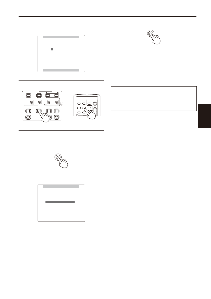
Push the Operation lever in the q direction to
TC PRESET
PUSH MENU TO RETURN
MONTH
+/– : PUSH q / g
1 0 h 0 0 m 0 0 s 0 0 f
SEL : PUSH t / y
BARS
CH1 SELECT
RESET/TC SET
REC
CH2 SELECT
AUDIO
INT(L)
INPUT1
INPUT2
SHUTTER
SPEES SELECT
INT(R)
INPUT2
INPUT1
MIC POWER+48V
ON
OFF
INPUT2
ON
OFF
LCD
ZEBRA
EVF DTL
OIS
WFM
OSD
COUNTER
RESET TITLE
VOL +
MULTI/
P-IN-P
REC A.DUB
PLAY/REW FF/
ZOOM
DATE/
TIME
PHOTO
SHOT
START/
STOP
-
COUNTER
MENU
TC PRESET
PRESET OK?
YES –– –PUSH STILL
NO
MENU
move to the next digit, then push it in the e or
direction to select a value.
r
You can reset the time code to zero by pressing
RESET on the camera or the remote control.
7 Press MENU twice to exit the menus.
With this unit, the time code value is adjusted in
accordance with the format and frame rate. For
this reason, bear in mind that making a change in
the format or frame rate may result in discontinuity
from the last time code value of the previous
recording.
Recording format
Frame
rate
720P/25PN —
Time code
adjustment
Adjustable
in 2-frame
increments
Camera or Remote control
5 Press the MENU button when you have
nished setting the time code.
6 Push the Operation lever in the
to move to YES and press it again.
direction
e
Shooting
59
Page 60

RECORDING SETUP
PUSH MENU TO RETURN
MIC GAIN2 -50dB
2CH
DF
REC RUN
–– ––
USER
–– ––
OFF
25M REC CH SEL
UB MODE
UB PRESET
TC MODE
TCG
TC PRESET
TIME STANP
RECORDING SETUP
PUSH MENU TO RETURN
MIC GAIN2 -50dB
2CH
DF
REC RUN
–– ––
USER
–– ––
OFF
25M REC CH SEL
UB MODE
UB PRESET
TC MODE
TCG
TC PRESET
TIME STANP
RECORDING SETUP
PUSH MENU TO RETURN
MIC GAIN2 -50dB
2CH
DF
REC RUN
–– ––
USER
–– ––
YES
25M REC CH SEL
UB MODE
UB PRESET
TC MODE
TCG
TC PRESET
TIME STANP
UB PRESET
PUSH MENU TO RETURN
MONTH
+/– : PUSH q / g
0 0 0 0 0 0 0 0
SEL : PUSH t / y
UB PRESET
PUSH MENU TO RETURN
MONTH
+/– : PUSH q / g
F 0 0 0 0 0 0 0
SEL : PUSH t / y
BARS
CH1 SELECT
RESET/TC SET
REC
CH2 SELECT
AUDIO
INT(L)
INPUT1
INPUT2
SHUTTER
SPEES SELECT
INT(R)
INPUT2
INPUT1
MIC POWER+48V
ON
OFF
INPUT2
ON
OFF
LCD
ZEBRA
EVF DTL
OIS
WFM
OSD
COUNTER
RESET TITLE
VOL +
MULTI/
P-IN-P
REC A.DUB
PLAY/REW FF/
ZOOM
DATE/
TIME
PHOTO
SHOT
START/
STOP
-
COUNTER
MENU
Charging the built-in battery/Setting the time data (continued)
Setting user information
Setting user information allows you to store 8-digit
memo (information such as the date and time) in
the hexagonal format on the sub code track area.
User information is automatically saved in the
memory and retained after you turn off the power.
1 Set the POWER switch to ON.
2 In the setup menus, RECORDING SETUP
screen UB MODE, select USER.
For menu operation (Page 93)
•
You can also use the menu buttons on the
•
remote control. (Page 13)
Example: In the CAM mode
3 Push the Operation lever in the
direction to move to UB PRESET and press
it again.
e
or r
5 Set the user information.
Push the Operation lever in the e or r
direction to select user information characters.
You can use numbers from 0 to 9 and letters
•
from A to F.
Push the Operation lever in the q direction to
move to the next digit, then push it in the er
direction to select a character.
You can reset the user information to nothing by
pressing RESET on the camera or the remote
control.
4 Push the Operation lever in the
to move to YES and press it again.
60
direction
r
Camera or Remote control
6 Press the MENU button when you have
nished setting the user information.
Page 61

7 Push the Operation lever in the
UB PRESET
PRESET OK?
YES –– –PUSH STILL
NO
MENU
direction
e
to move to YES and press it again.
8 Press MENU twice to exit the menus.
Shooting
61
Page 62

Basic playback operations
SLOT SEL
MODE
CAM
MCR
PC
POWER
ON
OFF
1
2
INDEX STOP INDEX
STILL ADV
PAUSE
STILL ADV
PLAY
INDEX STOP
V
-
/REW FF/
INDEX STOP INDEX
STILL ADV
PAUSE
STILL ADV
PLAY
INDEX STOP
V
-
/REW FF/
INDEX STOP INDEX
STILL ADV
PAUSE
STILL ADV
PLAY
INDEX STOP
V
-
/REW FF/
INDEX STOP INDEX
STILL ADV
PAUSE
STILL ADV
PLAY
INDEX STOP
V
-
/REW FF/
INDEX STOP INDEX
STILL ADV
PAUSE
STILL ADV
PLAY
INDEX STOP
V
-
/REW FF/
1 Turn the POWER switch to ON.
While pressing the lock release, turn the
POWER switch to ON.
2 Press the mode button so the MCR lamp
Lock release
For details on playing back clips using thumbnails, see Page 63.
Operations using the Operation lever Remote Control
Play ( q)
Use this button in stop mode to start playback from the
beginning of the selected clip.
During playback, the unit enters the variable speed search
mode and starts 1x playback. (Page 73)
Fast-forward ( y)
Use this button during playback to fast-forward the selected
clip (4 x speed).
When the thumbnail screen is cancelled, you can also
perform this operation while the camera is stopped. When
this button is held down, the playback speed becomes faster
(32x speed).
When pressed during a pause, playback advances one clip.
Rewind (t )
Use this button during playback to rewind the selected clip
(4 x speed).
When the thumbnail screen is cancelled, you can also
perform this operation while the camera is stopped.When
this button is held down, the playback speed becomes faster
(32x speed).
When pressed during a pause, playback goes back one clip.
Stop ( g )
turns on.
The camera is now in the MCR mode.
Each time you press the button, the mode
•
changes as below.
MCR v CAM
When you press the mode button while
MCR is selected, the unit enters the PC (PC
connection) mode. (Page 80)
62
Pause ( h )
Press again to return to playback.
Page 63

Thumbnail screen
MENU
PUSH-SET
PAGE/AUDIO MON/VAR
THUMBNAIL
1 2
MENU
PUSH-SET
PAGE/AUDIO MON/VAR
THUMBNAIL
1 2
Video data created on the P2 card in one shooting session is called a clip. When the MCR mode has been
established, the clips will be displayed on the LCD screen as thumbnails. (When there is a large number of
clips, it will take some time for them to be displayed on the screen.)
You can perform the following operations using the thumbnail screen.
Play, repair and delete clips, add and delete shot marks, as well as add text memos.
•
Format P2 cards and SD memory cards.
•
Load the metadata (shooting information, etc.) from SD memory cards to the unit.
•
Basic thumbnail screen operations
To use the thumbnail menu:
1 On the thumbnail screen, press the MENU button to display the menu.
2 Push the Operation lever in the
it in the q direction).
If another menu appears, repeat this step.
To return to the previous screen, select EXIT and press the Operation
•
lever or push it in the w direction.
To release the menu mode, press MENU.
•
To select a clip: Push the Operation lever in the w or q direction to move the yellow frame to the clip you
want to select, and press it again. (The frame changes to blue.) Pressing the Operation lever a second
time deselects the thumbnail. To scroll the pages, press the PAGE (- or +) button.
To Play back clips: Select a thumbnail and push the Operation lever in the q (playback) direction. (For
details on playback, see Page 62.)
Only clips recorded in the same format as the playback format (6 in the gure below) can be played
•
back.
or r direction and press it (or push
e
1
2
3
4
5
6
THUMBNAIL OPERATION
ALL CLIP
SAME FORMAT CLIPS
SELECTED CLIPS
MARKED CLIPS
TEXT MEMO CLIPS
SLOT CLIPS
DELETE
FORMAT
REPAIR CLIP
RE-CONNECTION
EXCH. THUMBNAIL
EXIT
PROPERTY META DATA
CLIP PROPERTY
CARD STATUS
DEVICES
PROPERTY SETUP
SYSTEM INFO
EXIT
7
8
LOAD
RECORD
USER CLIP NAME
INITIALIZE
PROPERTY
EXIT
SETUP
EXIT
Thumbnail screens are output only from the VIDEO OUT terminal.
•
Playback
(Continued on the next page)
63
Page 64

Thumbnail screen (continued)
1 Slot number display
The number of the slot with the P2 card
containing the clip indicated by the yellow
frame is shown here. (The number appears in
yellow.) If a clip extends over the P2 cards in
two slots, both numbers will appear in yellow.
When one of the following warnings applies
•
to an inserted P2 card, the frame around the
slot number turns pink.
1) RUN DOWN CARD (Page 90)
2) DIR ENTRY NG CARD (Page 90)
2 Thumbnails
This is where the images representing the clips
are displayed. (The initial images are displayed
in the default setting.)
3 Thumbnail display status (Page 66)
The types of clips displayed as thumbnails
appear in this area.
4 Clip numbers
The clips are displayed in the order in which
they were shot. (up to 2000)
Clips in the wrong recording format or clips
which cannot be played back for other reasons
are shown in red.
To play back clips indicated in red, change
the playback format while the thumbnail is
displayed (Page 67), or change the MCR
FORMAT and 576i MCR MODE on the setup
menu RECORDING SETUP screen to the
format described in 6 below. (Page 103)
Clips on the playlist which have been edited
•
and copied using the AJ-SPD850 memory
card recorder or other such unit and which
have more than one format (DV, DVCPRO
or DVCPRO50) are shown in red, and these
clips cannot be played back even when the
MCR FORMAT item has been set.
5 Menu display
This is where the menu items are displayed.
Select EXIT and press the Operation lever
to close the menu and return to the original
screen.
6 Recording mode/format display
This is where the recording mode and format
of the recorded images are displayed.
7 Indicators
: Shot mark
M
This indicates that a clip has a shot mark.
: Wide
W
This indicates that a clip has been recorded
in the 16:9 aspect ratio (wide screen). (576i
recording)
: Incomplete clip
!
This indicator appears when the recording of a
clip extends over two P2 cards and one of the
cards is not found in the slot.
: Defective clip
X
This indicator appears for a clip whose
recording was defective because the power
was cut off during the recording process, for
instance.
Clips indicated by the yellow defective clip
indicator can be repaired.
Clips indicated by the red defective clip
indicator cannot be repaired so delete them. If
a clip cannot be deleted, rst back up its data,
and then format the P2 card. Clips in the wrong
format are indicated by ( ? ) instead.
: Text memo
T
This indicates that a clip has a text memo.
: Edit copy
E
This indicates that this is an edit copy clip. (You
cannot perform editing with this camera.)
: Proxy
P
This indicates that a proxy has been added
and recorded. (You cannot perform recording
with this camera.)
8 Duration display
This displays the duration of the selected clip.
64
Page 65

Adding shot marks to clips
THUMBNAIL
Adding shot marks ( M ) will make it easier to nd
the clips you are looking for.
1 Push the Operation lever in the
direction to move the yellow frame to the
clip to which you will add a shot mark.
w
or q
2 Press the USER button to which the shot
mark function has been allocated. (Page 41)
To release a shot mark, repeat the above steps.
When the video data of a single shot is recorded
•
in multiple P2 cards, you cannot set or release
shot marks unless all the P2 cards that make up
the video data are inserted into slots.
Clearing the thumbnail screen
Before performing setting menu operations
(Page 93), you must clear the thumbnail screen.
Release this in the same way when the camerarecorder is to be controlled from a nonlinear editor.
1 Press the THUMBNAIL button.
The normal playback standby screen (1394 input
mode) appears.
Direct shooting functions
If you press the START/STOP button (red) in MCR
mode, CAM mode will be automatically activated,
and shooting will start.
Playback
65
Page 66

Thumbnail operations
THUMBNAIL
OPERATION
PROPERTY
META DATA
EXIT
THUMBNAIL
OPERATION
PROPERTY
META DATA
EXIT
ALL CLIP
SAME FORMAT CLIPS
SELECTED CLIPS
MARKED CLIPS
TEXT MEMO CLIPS
SLOT CLIPS
SETUP
EXIT
Selecting the thumbnail display method (THUMBNAIL)
You can display the kind of clips you want to see as
thumbnails.
You can also set more precisely how you want the
thumbnails to appear on the screen.
1 On the thumbnail screen, press the MENU
button.
A menu now appears. (Page 63)
2 Push the Operation lever in the
direction to select THUMBNAIL and press it
(or push it in the q direction) again.
3 Push the Operation lever in the
direction to make a selection and press it
again.
e
e
or r
or r
To delete a text memo:
1) Move the yellow frame to the clip whose
2) Select the thumbnail of the text memo to
3) Press the MENU button to display
SLOT CLIPS:
The clips on the P2 card in the specied slot
are displayed.
SETUP:
Various setup operations are performed.
EXIT:
Select this to return to the last screen.
Proceed to step 4 only when you have selected
SETUP.
text memo is to be deleted, and press
the Operation lever. A thumbnail of the
text memo now appears.
be deleted.
the menu, and select OPERATIONDELETE.
ALL CLIP:
SAME FORMAT CLIPS:
SELECTED CLIPS:
MARKED CLIPS:
TEXT MEMO CLIPS:
66
All the clips are displayed.
The clips in the format same as the MCR
format are displayed.
The clips you have selected are displayed.
The clips with shot marks are displayed.
The clips with text memos are displayed.
The thumbnails at text memo positions, time
codes (TC), total number of memos and the
current order of the clips are displayed.
4 Push the Operation lever in the
direction to select an item and press it
again.
ALL HIDE:
Selecting ON hides MARKED IND., TEXT
MEMO IND., WIDE IND. and PROXY IND.
MARKED IND.:
Select this to set whether the shot mark
indicator is to be displayed (ON/OFF).
TEXT MEMO IND.:
Select this to set whether the text memo
indicator is to be displayed (ON/OFF).
WIDE IND.:
Select this to set whether the wide indicator
is to be displayed (ON/OFF).
PROXY IND.:
Select this to set whether the proxy indicator
is to be displayed (ON/OFF).
DATA DISPLAY:
Select the time code (TC), user information
(UB), shooting time (TIME), shooting date
(DATE), shooting date (DATE TIME) or user
clip name (USER CLIP NAME) for the area
where the clip time is displayed.
or r
e
Page 67

DATE FORMAT:
THUMBNAIL
OPERATION
PROPERTY
META DATA
EXIT
THUMBNAIL
OPERATION
PROPERTY
META DATA
EXIT
DELETE
FORMAT
REPAIR CLIP
RE-CONNECTION
EXCH. THUMBNAIL
EXIT
Select year/month/day (YMD), month/day/
year (MDY) or day/month/year (DMY) as the
order for displaying the recording date/time.
This format will be the same for the recording
date displayed by the clip properties and the
recording date displayed by DATA DISPLAY.
THUMBNAIL SIZE:
Select LARGE (3x2) or NORMAL (4x3) for
full-screen displays of thumbnails.
PLAYBACK RESUME:
Resumes playback from the point where a
previous playback operations was halted.
THUMBNAIL INIT:
Select this to return all the above settings to
the factory (initialization) settings.
EXIT:
Select this to return to the last screen.
5 Press the MENU button to release the menu
mode.
Changing playback format
Use the following steps to change the playback
format in order to play back a clip in a playback
format (a clip whose clip number is indicated in
red) that differs from that currently selected.
1 Use the Operation lever in the thumbnail
screen to move to the clip you want to play
back.
Deleting clips and formatting cards (OPERATION)
You can perform any of the following operations. If
necessary, make preparations prior to undertaking
the operations.
Deleting clips
Select the clip to be deleted.
•
Formatting P2 cards or SD memory cards
Insert the card to be formatted into the unit.
•
When a card is formatted, all its data will be
•
deleted.
Repairing bad clips
Select the bad clip (indicated by X ) you want
•
to repair. (Note that clips indicated by a red X
symbol cannot be repaired.)
Reconnecting incomplete clips
Select an incomplete clip (indicated by “ ! ”) you
•
want to reconnect. Incomplete clips are usually
grouped together.
Replacing thumbnails
Attach text memos to clips and change them to
•
TEXT MEMO CLIPS.
Move the yellow frame to the thumbnail you want
•
to edit.
1 On the thumbnail screen, press the MENU
button.
A menu now appears. (Page 63)
2 Push the Operation lever in the
direction to select OPERATION and press it
(or push it in the q direction) again.
or r
e
Playback
2 Push the Operation lever in the
and hold it down for 2 or more seconds.
Thumbnail status indicates “UPDATING…”
•
after which the previous screen reappears.
When the recording format of a clip indicated
•
by the yellow frame is a format playable by
this unit, the playback format changes to
enable playback of the clip with the yellow
frame.
direction
r
3 Push the Operation lever in the
direction to make a selection and press it
again.
or r
e
67
Page 68

THUMBNAIL
OPERATION
PROPERTY
META DATA
EXIT
THUMBNAIL
OPERATION
PROPERTY
META DATA
EXIT
CLIP PROPERTY
CARD STATUS
DEVICES
PROPERTY SETUP
SYSTEM INFO
EXIT
Thumbnail operations (continued)
DELETE:
Select this to delete the selected clip.
Select YES to delete the clip or NO to cancel
the deletion, and press the Operation lever.
FORMAT:
Select this to format a P2 card or SD
memory card.
When you move to FORMAT, the card
selection screen will appear. Select the P2
slot (SLOT1 or SLOT2) or select SD CARD,
and press the Operation lever. Select YES
to format the card or NO to cancel the
formatting, and press the Operation lever.
REPAIR CLIP:
Select this to repair defective clips.
Select YES to repair the clip or NO to cancel
the repair, and press the Operation lever.
The SHOT MARK and TEXT MEMO data
•
are deleted when a clip is repaired.
RE-CONNECTION:
Use this function to reconnect clips that span
multiple P2 cards.
Clips recorded across multiple P2 cards may
become incomplete clips.
Should this happen, use the RECONNECTION function to merge the
different clips to create one single clip.
Select YES/NO and push the Operation lever.
EXCH. THUMBNAIL:
Use this function to replace thumbnail
images with images to which text memos
have been attached.
Select YES/NO and push the Operation lever.
EXIT:
Select this to return to the last screen.
Checking the clip or card information (PROPERTY)
You can perform any of the following operations. If
necessary, make preparations prior to undertaking
the operations.
Checking clip information
Move the yellow frame to the clip to be checked.
•
Checking the P2 card information
Insert the P2 card into the unit.
•
Checking the SD memory card information
Insert the SD memory card into the unit.
•
Setting the P2 card memory capacity display
Checking the version of this system
1 On the thumbnail screen, press the MENU
button.
A menu now appears. (Page 63)
2 Push the Operation lever in the
direction to select PROPERTY and press it
(or push it in the q direction) again.
3 Push the Operation lever in the
direction to make a selection and press it
again.
or r
e
or r
e
4 Press the MENU button to release the menu
mode.
When clips have been copied by operating
•
Explorer, for instance, the “ ! ” indicator may
appear on the clips. If this happens, “ ! ” can
sometimes be released by downloading the latest
version of the P2 viewer from the web site given
below, installing it in your computer, and copying
the clips again.
https://eww.pavc.panasonic.co.jp/pro-av/
68
CLIP PROPERTY:
The information of the clip indicated by the
yellow frame is displayed. (Page 69)
CARD STATUS:
The P2 card information is displayed.
(Page 69)
DEVICES:
The SD memory card information is
displayed. (Page 70)
PROPERTY SETUP:
Set the method of displaying the P2 card
memory capacity. After selecting the P2
CARD CAP, select REMAIN (remaining
memory) or USED (memory used), and
press the Operation lever.
Page 69

SYSTEM INFO:
The version of the system in this camera is
displayed.
EXIT:
Select this to return to the last screen.
Pressing the DISP/MODE CHK button in a
•
thumbnail screen displays the CLIP PROPERTY
screen. Press the button again to return to the
thumbnail screen.
4 To exit the information screen, press the
MENU button, push the Operation lever in
the q direction to select EXIT, and press it
again.
Clip information screen
1 2 3
4 5
1 Clip number
2 Thumbnail
3 Slot number
4 Clip information
Various indicators that have been added
to the clip and also various kinds of data
are displayed. ( appears if the P2 card is
writeprotected)
CLIP NAME: Clip name
START TC: Time code value when recording
started
START UB: User information value when
recording started
DATE: Date when the recording was made
TIME: Time when recording started
DURATION: Clip length
V_FORMAT: Video signal format
FRAME RATE: Playback frame rate
REC RATE: Recording frame rate
This display appears when recording using
•
a setting for the FRAME RATE item on the
SCENE FILE screen other than the default
during 720P/25PN recording operations.
5 Clip metadata
The video and audio formats, videographer
information and other detailed data are
displayed here.
Select the desired item using the Operation
lever, and press the Operation lever. (For
details on the clip metadata, see Page 56.)
P2 card information screen
1 2
1 Write protection mark
2 P2 card status
The amount of memory remaining on the P2
card is displayed using a percentage bar. The
following displays may appear, depending on
the card status.
FORMAT ERROR: An unformatted P2 card
has been inserted.
NOT SUPPORTED: A card not supported by
the unit has been inserted.
NO CARD: A card has not been inserted.
The information on the card in the slot
•
indicated by the yellow frame (with yellow
number) can be viewed by pressing the
Operation lever.
BRAND: Name of manufacturer
MODEL NO.: Model number
SERIAL NO.: Serial number
USER ID: User ID
WARNING: Warning information
3 P2 card remaining memory/total memory
The P2 card’s remaining memory and total
memory are displayed here in 1-minute
increments. Fractions of a minute are rounded
off, meaning the display may not match the
slot total.
(Continued on the next page)
3
4
5
Playback
69
Page 70

Thumbnail operations (continued)
4 Card warning mark
This mark is displayed when one of the
following warnings applies to a P2 card.
1) RUN DOWN CARD (Page 90)
2) DIR ENTRY NG CARD (Page 90)
The contents of the warning can be viewed
•
by checking the card information as
described above.
5 Slot total
The gure represents the total remaining
memory of the cards in the two slots. If a P2
card is write-protected, its remaining memory
will not be included in the total remaining
memory.
When LOOP is set under REC FUNCTION,
•
the slot total represents the standard
recording time for loop recording.
However, note that when PROPERTY
SETUP: USED is selected in step 3 on the
previous page, the used amount displayed
by the slot total will be larger than the actual
amount, and when PROPERTY SETUP:
REMAIN is selected, the remaining amount
displayed by the slot total will be smaller than
the actual amount. (Page 46)
SD memory card information screen
Editing the recorded clip metadata
1 On the clip information screen, display the
detailed clip metadata screen.
2 Use the Operation lever to move the cursor
to the item to be edited.
Metadata that can be edited, such as “USER
CLIP NAME”, is displayed as shown in the
following example.
3 Press the Operation lever.
The metadata editing screen (on-screen
keyboard) is displayed.
Enter characters using the on-screen keyboard
to edit the metadata.
SD STANDARD: This indicates whether the SD
memory card was formatted in
compliance with the SD or SDHC
standard. (SUPPORTED/NOT
SUPPORTED).
USED: Space used
BLANK: Space available
TOTAL: Total space
NUMBER OF CLIPS: Number of clips
PROTECT: This indicates that the SD memory
card is writeprotected.
70
4 Press the “OK” button on the on-screen
keyboard.
The edited metadata is written to the clip, and
the detailed clip metadata screen returns.
When deleting items of LOCATION (shooting
•
location) in SHOOT, items cannot be deleted
independently. Make ALTITUDE blank, and the
other items (LONGITUDE/LATITUDE) are also
deleted.
Page 71

Metadata of a clip with the incomplete clip
THUMBNAIL
OPERATION
PROPERTY
META DATA
EXIT
THUMBNAIL
OPERATION
PROPERTY
META DATA
EXIT
LOAD
RECORD
USER CLIP NAME
INITIALIZE
PROPERTY
EXIT
•
indicator cannot be edited. To edit metadata of a
clip recorded in multiple P2 cards, insert all the
P2 cards containing video data of the clip before
starting editing.
If MEMO contains 100 or more characters, it
•
cannot be edited.
3 Push the Operation lever in the
direction to make a selection and press it
again.
or r
e
Uploading the metadata (META DATA)
You can perform any of the following operations. If
necessary, make preparations prior to undertaking
the operations.
Loading the metadata
Insert the SD memory card on which the
•
metadata is recorded into the unit. (For details on
creating the metadata, see Page 56.)
Selecting whether to record the metadata on
the P2 card
Changing recording method of USER CLIP
NAME
Initializing the metadata inside the unit
Conrming and editing camera-recorder
metadata
1 On the thumbnail screen, press the MENU
button.
A menu now appears. (Page 63)
2 Push the Operation lever in the
direction to select META DATA and press it
(or push it in the q direction) again.
e
or r
LOAD:
Select this to load the metadata recorded on
the SD memory card into the unit.
When the Operation lever is pressed with
operation moved to LOAD, the metadata
on the SD memory card will be displayed.
Therefore, press the Operation lever again.
Select YES to load the metadata or NO to
cancel the loading, and press the Operation
lever.
If characters other than single-byte
•
alphanumeric characters are used in the
metadata le name to be loaded, they are
displayed as “∗”.
RECORD:
Select this to set whether to record the
metadata to be loaded into the unit
simultaneously on a P2 card.
Select ON to record the metadata or OFF
to cancel the recording, and press the
Operation lever. The factory setting for this
mode is OFF.
USER CLIP NAME:
The USER CLIP NAME recording method
is selectable. Please refer to Appendix
(Page 124).
INITIALIZE:
Select this to initialize the metadata which
has been recorded in the unit.
Select YES to initialize the metadata or NO
to cancel the initialization, and press the
Operation lever. All the settings including the
ON or OFF setting for RECORD are now
cleared.
Playback
(Continued on the next page)
71
Page 72

Thumbnail operations (continued)
PROPERTY:
Select this to display the metadata which has
been recorded in the unit.
Push the Operation lever in the e or r
direction, select PROPERTY and push the
Operation lever to view the desired data. The
Operation lever also allows you to change
the data.
Changing method is the same as described
in “Editing the recorded clip metadata”.
(Page 70)
EXIT:
Select this to return to the last screen.
4 Press the MENU button to release the menu
mode.
72
Page 73

INDEX
SELECT
STORE
OFF/ON
P.B.DIGITAL
VAR.
SEARCH
PB.
ZOOM
MENU
SET
ITEM
STOP INDEX
MENU
PUSH-SET
PAGE/AUDIO MON/VAR
THUMBNAIL
INDEX
SELECT
STORE
OFF/ON
P.B.DIGITAL
VAR.
SEARCH
PB.
ZOOM
MENU
SET
ITEM
STOP INDEX
INDEX STOP INDEX
STILL ADV
PAUSE
STILL ADV
PLAY
INDEX STOP
V
-
/REW FF/
STILL ADV
PAUSE
STILL ADV
INDEX
VOL+
-
STOP INDEX
P-IN-P
REC A.DUB
PLAY/REW FF/
MENU
PUSH-SET
PAGE/AUDIO MON/VAR
THUMBNAIL
INDEX STOP INDEX
STILL ADV
PAUSE
STILL ADV
PLAY
INDEX STOP
V
-
/REW FF/
Useful playback functions
Variable speed search
This function enables you to change the playback
speed and search for specic scenes.
1 Press the Operation lever in the
q
(playback) direction during playback.
On the remote control, press the VAR.
SEARCH button.
Camera or Remote control
[1x] appears on the screen and the media is
played back at the normal speed.
2 Press the PAGE/AUDIO MON/VAR button to
change the playback speed.
On the remote control, press the [ ] or [ ]
button.
The playback speed increases as follows
•
each time you press the button; 1/5x, 1x, 2x,
4x, 12x, and 24x. Audio is not played at 12×
or 24× speed.
Press the “+” button to increase the speed
•
and the “-” button to decrease the speed.
Fast forward/rewind playback
1 During playback, push the Operation lever
in the t (rewind) or y (fast-forward)
direction.
This performs fast forward/rewind playback at
4x speed.
When this button is held down, the playback
speed becomes faster (32x speed).
Camera or Remote control
To return to normal playback, push the Operation
lever in the q (playback) direction.
Frame-by-frame playback
1 Press
(pause) during playback to set the
h
unit to the pause mode.
2 Press the PAGE/AUDIO MON/VAR button to
play frame-by-frame.
On the remote control unit, press the STILL
ADV ( or ) button.
Press and hold the button to perform
•
frameby-frame play continuously.
Playback
To return to normal playback, push the Operation
lever in the q direction (playback) or press the
VAR.SEARCH button on the remote control.
Slow playback
1 During play, press one of the STILL ADV (
or ) buttons on the remote control unit.
To return to normal playback, push the Operation
lever in the q (playback) direction.
Camera or Remote control
Camera or Remote control
To return to normal playback, push the Operation
lever in the q (playback) direction.
(Continued on the next page)
73
Page 74

Useful playback functions (continued)
STILL ADV
PAUSE
STILL ADV
INDEX
VOL+
-
STOP INDEX
P-IN-P
REC A.DUB
PLAY/REW FF/
MENU
PUSH-SET
PAGE/AUDIO MON/VAR
THUMBNAIL
OSD
COUNTER
RESET TITLE
VOL+
-
MULTI/
P-IN-P
REC A.DUB
PLAY/REW FF/
ZOOM
DATE/
TIME
PHOTO
SHOT
START/
STOP
OSD
COUNTER
RESET TITLE
VOL+
-
MULTI/
P-IN-P
REC A.DUB
PLAY/REW FF/
ZOOM
DATE/
TIME
PHOTO
SHOT
START/
STOP
OSD
COUNTER
RESET TITLE
MULTI/
ZOOM
DATE/
TIME
PHOTO
SHOT
START/
STOP
OSD
COUNTER
RESET TITLE
MULTI/
ZOOM
DATE/
TIME
PHOTO
SHOT
START/
STOP
Clip skip
1 Press
2 Push the Operation lever in the
(pause) during playback to set the
h
unit to the pause mode.
or y (fast-forward) direction.
Camera or Remote control
t
(rewind)
Adjusting the volume
Camera or Remote control
1 With the PAGE/AUDIO MON/VAR button,
adjust the volume of the sound that is
output from the internal speaker and
headphone jack.
On the remote control, press the ZOOM/VOL
button.
Viewing images on a monitor
You can view the images on a monitor if you
connect the unit to a monitor using a BNC cable
(not included), an AV cable (not included), or
component video cable (included).
1 Connect the camera-recorder to the TV set.
(Page 79)
2 Start playback.
To show the information that appears on the
•
viewnder and LCD, press the OSD button
on the remote control. Press the OSD button
again to clear the display.
Checking the date and time
Press the DATE/TIME button on the remote control
to show the date and time of shooting on the
screen. The display changes as follows each time
you press the button.
Time
Date
Time and Date
No display
74
Page 75

Connecting external units
Headphones
3.5-mm stereo mini jack
Sound is no longer heard from the speaker when the headphones are connected.
•
External microphone
Microphone (optional)
AG-MC200G
Microphone
holder adapter
Microphone holder
INPUT1 or INPUT2
6 mm
When attaching an external microphone to the microphone shoe, use the supplied microphone holder
•
and microphone holder adapter.
When attaching the microphone holder and the microphone holder adapter, be sure to tighten the screws
•
rmly even though you might hear a squeaking sound.
12 mm
Editing
75
Page 76
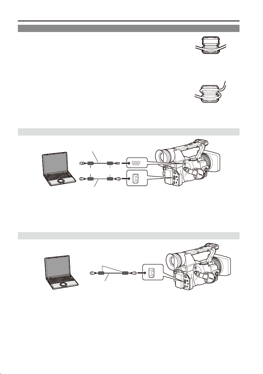
76
Connecting external units (continued)
USB 2.0
1394
1394
Computer (non-linear editing/le transfer)
When connecting a 1394 cable
Attach the provided two ferrite cores (length: 30 mm) to the both ends of
•
the cable. After passing the cable as shown in the gure on the right, close
the ferrite cores until they click into place and lock.
Always take sufcient care when handling the ferrite core, as it can be easily
damaged when dropped or subjected to other impact.
When connecting a USB cable
Attach the provided two ferrite cores (length: 35 mm) in such a way that the
•
whole ferrite cores t within about 5 cm from both ends of the cable. After
threading the cable as shown in the gure on the right, close the ferrite
cores until they click into place and lock.
Always take sufcient care when handling the ferrite core, as it can be easily
damaged when dropped or subjected to other impact.
File transfer/nonlinear editing
USB cable (optional)
Computer
When connecting a USB cable, rst connect the cable to the PC.
•
When connecting to a device having 4-pin type 1394 connector, rst connect the cable to the 6-pin type
•
1394 connector on the camera.
For details on the computer’s conditions and other factors, see Page 80.
•
• For a Windows computer
Mini-B type
Ferrite core (included)
6-pin
1394 cable (optional)
• For an Apple Macintosh computer
Ferrite core (length: 30 mm)Ferrite core (length: 30 mm)
Ferrite core (length: 35 mm)Ferrite core (length: 35 mm)
1394 AVC transfer/nonlinear editing
Computer (Windows/Apple Macintosh)
Ferrite core (included)
1394 cable (optional)
When controlling this camera from a non-linear editor, cancel the thumbnail screen on the camera.
•
6-pin
(Page 65)
No guarantees are given for images and audio signals which are output simultaneously from the
•
camerarecorder while data is being transferred from a computer to the camera-recorder.
The model name will appear on the computer screen.
•
When connecting to a device having 4-pin type 1394 connector, rst connect the cable to the 6-pin type
•
1394 connector on the camera.
Page 77

When connecting the unit to an Apple Macintosh computer
1394
Connect the 1394 cable after turning on the power of the Apple Macintosh computer. Otherwise, the unit
•
may not be mounted.
The unit may not be recognized after the Apple Macintosh computer has been placed in the hibernation
•
state by its power-saving setting. In this case, disconnect the 1394 cable and then re-connect it.
If the unit is not mounted properly on an Apple Macintosh computer
When the P2 card access lamp ashes orange
•
1. Select [Applications] " [Utilities] " and start up [Disc Utility].
2. Select a grayed-out volume among volumes of the X.X GB Panasonic disc, and click “Mount.”
When the P2 card access lamp is off
•
Eject the P2 card, and insert it again. If the unit is still not mounted, disconnect the 1394 cable and then
re-connect it.
Hard disk drive (data copying)
Hard disk drive
Ferrite core (included)
1394 cable (optional)
Before proceeding to connect or disconnect 1394 cable, be absolutely sure to turn off the power of the
•
6-pin
units.
Before proceeding to connect the unit which uses a 6-pin type 1394
•
connector, carefully check the shape of the 1394 cable and the connectors
on the 1394 cable. Connecting a connector upside down may damage the
parts inside the unit and cause malfunctioning. The above also applies to
USB cable as well.
When connecting to a device having 4-pin type 1394 connector, rst
•
6-pin type 4-pin type 6-pin type 4-pin type
connect the cable to the 6-pin type 1394 connector on the camera.
Do not apply force when connecting 1394 cable to 1394 connector as this
•
may damage the connector.
Editing
77
Page 78

78
Connecting external units (continued)
1394
Digital video equipment (Dubbing)
This camera
Ferrite core (included)
Other Digital video equipment
Ferrite core (included)
6-pin
You can connect a digital video unit equipped with a 1394 connector and digitally transfer video
1394 cable (optional)
and audio signals as well as time code.
Before proceeding to connect or disconnect 1394 cable, be absolutely sure to turn off the power of the
•
units.
Before proceeding to connect the unit which uses a 6-pin type 1394
•
connector, carefully check the shape of the 1394 cable and the connectors
on the 1394 cable. Connecting a connector upside down may damage the
parts inside the unit and cause malfunctioning.
When connecting the camera to a device with a 4-pin type 1394 connector,
•
6-pin type 4-pin type 6-pin type 4-pin type
rst connect the 6-pin type connector of the cable to the camera.
When recording signals from an external unit, rst check that video signals are supplied.
•
While signals from an external unit are being recorded, do not stop output on the external unit side or
•
disconnect any of cables. This may lead to a failure to recognize the signals when you do recording
again.
While signals from an external unit are being recorded, do not change the format of the signals being
•
output from the external unit. Doing so may make it impossible to record correctly.
Do not apply force when connecting 1394 cable to 1394 connector as this may damage the connector.
•
When signals are input from an external unit via the 1394 cable, video is output from the terminals
•
such as the SDI OUT terminal, but the output video is only for check purpose and the quality is not
guaranteed. (Frame skip and overlap occur.)
The automatic recording function in the DVD unit may not function properly. In a case like this, proceed
•
with the recording manually.
Page 79

Video deck (Dubbing)
SDI
OUT
COMPONENT
OUT
SDI
OUT
COMPONENT
OUT
BNC cable
(optional)
Audio cable (optional)
White: CH1 (left
channel) sound
Red: CH2 (right
channel) sound
VCR
Component video
cable (included)
Video cable
Connect one of
these cables to
the terminal on
the video deck.
(optional)
AUTO REC function
When recording is started or stopped on this camera, recording start/stop information can be output
through the SDI (HD) connector to control external device.
* The external device should support this function.
TV/Monitor (playback/dubbing)
Audio cable (optional)
White: CH1 (left channel)
sound
BNC cable
(optional)
Component video
cable (included)
Video cable
(optional)
Red: CH2 (right channel)
sound
TV/Monitor
Connect
one of these
cables to the
terminal on
the television.
Editing
79
Page 80

OTHER FUNCTIONS
PUSH MENU TO RETURN
USER FILE –– ––
1
OFF
REC_P
1394DEVICE
ON
OFF
OFF
REMOTE
ACCESS LED
REC LAMP
1394 CONTROL
1394 CMD SEL
PC MODE
BEEP SOUND
OTHER FUNCTIONS
PUSH MENU TO RETURN
USER FILE –– ––
1
OFF
REC_P
USB DEVICE
1394DEVICE
1394 HOST
OFF
REMOTE
ACCESS LED
REC LAMP
1394 CONTROL
1394 CMD SEL
PC MODE
BEEP SOUND
MENU
Nonlinear editing with P2 card (PC mode)
You can edit the video data on P2 cards nonlinearly
by connecting the unit to a computer used for
editing by means of a USB cable (Windows) or
1394 cable (Apple Macintosh).*1 (Connections :
Page 76)
*1 When the unit is connected to a computer with
a 1394 cable, you can only read data from P2
cards but you cannot write data to P2 cards.
The following conditions must be met if
the USB cable is to be used to make the
connection.
Your computer must run Windows 2000,
•
Windows XP or Windows Vista.
USB dedicated driver (provided on the
•
CD-ROM supplied) must be installed in your
computer.
Your computer must support USB2.0 (High
•
Speed, Mass Storage Class). (USB 1.1 is not
supported.)
Only one computer can be connected.
•
When the unit is connected via USB cable,
•
the series name of the unit should appear on
the computer screen.
No operations can be performed if a hub or
•
other unit is connected between the unit and
your computer.
Do not use a USB cable longer than 3 meters.
•
Otherwise, malfunctions may occur.
Operation is not guaranteed in Macintosh
•
operating systems.
The following conditions must be met if
the 1394 cable is to be used to make the
connection.
Your computer must run Apple MacOSX 10.3
•
or later.
Your computer must support 1394.a (SBP2
•
protocol).
Operation is not guaranteed in Windows
•
operating systems.
Insert the P2 card into the unit. (Page 24)
•
1 Set the unit’s POWER switch to ON.
2 Select PC MODE on the setting menu
OTHER FUNCTIONS screen and press
the Operation lever (or push it in the q
direction).
•
For menu operations (Page 93)
•
You can also use the menu buttons on the
remote control. (Page 13)
3 Push the Operation lever in the
or r
e
direction to select a USB DEVICE or 1394
DEVICE and press it again.
4 Press the MENU button twice to release
menu mode.
5 Press the mode button to light up the MCR
lamp and then hold the button down (for 2
or more seconds).
The PC lamp now lights, and PC mode is
established.
When the P2 card is in an accessible status,
USB (or 1394) DEVICE CONNECT is
displayed on the camera.
(If DISCONNECT is displayed, you cannot
operate the camera.)
80
Page 81

6 Proceed with nonlinear editing using your
computer.
An icon for the P2 card contents appears as
a removable disk in My Computer of your
computer.
For further details, refer to the instructions for
•
your computer’s editing software.
When replacing one card with another, if
•
the USB connection is used, check that the
access lamp is not ashing and that the data
on the card is not being accessed before
ejecting the card. If the 1394 connection is
used, place the drive icon into the computer’s
recycle bin before ejecting the card.
The unit cannot be operated while in PC
•
mode.
When the cable is to be disconnected,
•
proceed with “Safely Remove Hardware” on
the computer.
In the case of a 1394 connection, rst
conrm that “1394 DEVICE DISCONNECT”
is displayed on the camera-recorder before
disconnecting the cable. In the case of a
USB connection, “USB DEVICE CONNECT”
will remain displayed so check that the card
is not being accessed before disconnecting
the cable.
7 Switch OFF the camera.
When turning the power off, proceed with
•
“Safely Remove Hardware” on the computer.
In the case of a 1394 connection, rst
conrm that “1394 DEVICE DISCONNECT”
is displayed on the camera-recorder before
turning the power off. In the case of a USB
connection, “USB DEVICE CONNECT” will
remain displayed so check that the card is
not being accessed before turning the power
off.
You cannot cancel the PC mode even if
•
you press the mode button for more than 2
seconds.
Editing
P2 cards are compliant with the Type-II
standard so you can insert them straight
into the computer’s card slots and proceed
with nonlinear editing.
The Card Bus driver is contained in the CD-
•
ROM provided.
81
Page 82

OTHER FUNCTIONS
PUSH MENU TO RETURN
USER FILE –– ––
1
OFF
REC_P
USB DEVICE
1394DEVICE
1394 HOST
OFF
REMOTE
ACCESS LED
REC LAMP
1394 CONTROL
1394 CMD SEL
PC MODE
BEEP SOUND
MENU
MODE
CAM
MCR
PC
COPY TO HDD
FORMAT (HDD)
PROPERTY
SETUP
COPY TO HDD
FORMAT (HDD)
PROPERTY
SETUP
COPY TO HDD
FORMAT (HDD)
PROPERTY
SETUP
SLOT1
SLOT2
EXIT
SURE?
YES
NO
Copying from P2 cards to the hard disk drive (1394 HOST mode)
Use an HDD (hard disk drive) that has sufcient
•
capacity to permit copying.
Before copying the data, format the hard disk
•
drive so that it can be used by the unit. Bear in
mind that this process will delete all the data on
the drive.
Connect the camera to an HDD using the 1394
•
cable. (Page 77)
Do not connect the camera to two or more HDD
•
(chain, hub, etc.), even if they are not turned ON.
Insert the P2 card into the unit. (Page 24)
•
1 First turn on the power of the HDD (1394.
a SBP2 supported) to be connected, and
connect it using the 1394 cable. Then turn
the unit’s POWER switch to ON.
2 Select 1394 HOST for PC MODE on the
setting menu OTHER FUNCTIONS screen,
and press the Operation lever.
For menu operations (Page 93)
•
5 Only when the hard disk drive is not
formatted:
Push the Operation lever in the e or r
direction to select FORMAT (HDD) and
press it again.
Then push the Operation lever in the e or r
direction to select YES and press it again.
Formatting now starts. (Formatting is
completed in about 2 to 3 seconds.)
6 When formatting is complete:
Push the Operation lever in the e or r
direction to select COPY TO HDD and press
it again.
Data is copied onto the HDD on a card by
•
card basis.
3 Press the MENU button twice to release the
menu mode.
4 Press the mode button to light up the MCR
lamp, and then hold the button down for 2
or more seconds.
The PC lamp now lights, and PC mode is
established.
82
7 Push the Operation lever in the
e
direction to select a card slot and press it
again.
Then push the Operation lever in the e or r
direction to select YES and press it again.
Copying now starts.
You can carry out copying up to 15 times to
•
one HDD.
8 When copying is complete:
Switch OFF the camera.
You cannot cancel the 1394 HOST mode
•
even if you press the operation mode button
for more than 2 seconds.
or r
Page 83

To check the HDD status
The color of indicates the HDD status, as
below.
White: HDD is connected and can be used.
Black: HDD is not connected.
Red: Copy cannot be made to the HDD since it is
incorrectly formatted, etc.
When the color is red, correctly format the HDD
•
at step 5 before copying data onto it.
To check the data copied into the hard disk
drive
After completing step 4 on the previous page, push
the Operation lever in the e or r direction to select
PROPERTY and press it again.
The contents of the hard disk drive are displayed.
To view detailed hard disk data, push the
•
Operation lever in the e or r direction to select
an item and press it again.
To verify the data when copying it into the hard
disk drive
After completing step 4 on the previous page, push
the Operation lever in the e or r direction to select
YES for the VERIFY option under SETUP.
Copying to the P2 card is completed, even if you
•
interrupt processing during verication.
You cannot copy data from the hard disk drive
•
to a P2 card.
Use a hard disk drive under the following
•
conditions.
Power is supplied from a source other than
•
the 1394 bus. (It is not supplied from the
unit.)
You may format the hard disk drive for
•
usage by the unit.
Use the hard disk drive within the
•
guaranteed operating range (humidity and
other environmental conditions).
Do not place the hard disk drive in an
•
unstable locations or locations subjected to
vibrations.
Some HDD may not operate correctly.
•
During formatting or copying, do not remove
•
any cables, eject the P2 card, or turn off the
power for the unit or hard disk drive. The
power will need to be turned on again.
No guarantees are made for operation if the
•
1394 HOST mode is established without
rst connecting the HDD (1394.a SBP2
supported) and then the HDD is connected. In
this case, turn off the power, and then release
the 1394 HOST mode.
The hard disk drive is an extremely
•
highprecision device. Therefore, it is
highly possible that data cannot be read in
certain operating environments.
Please note that our company will not be
•
liable for any data losses due to hard disk
drive failure or other faults, or any other
direct or indirect damage related to these
problems.
If you rewrite the contents of the HDD
•
used to carry out copying from the camera
to another PC, the subsequent operation
in the camera and the data in the HDD
cannot be guaranteed.
Editing
It is recommended that you rst restore any
•
defective clips contained in the P2 card before
copying the data.
In order to avoid the occurrence of trouble in
•
copying, formatting or other operations, it is
recommended that you perform these operations
after ensuring that power supply has stabilized.
83
Page 84

84
Copying from P2 cards to the hard disk drive (1394 HOST mode) (continued)
Warnings
HDD CAPACITY FULL!
There is not enough free memory on the HDD.
TOO MANY PARTITIONS!
There are too many partitions. *
HDD DISCONNECTED!
The HDD has been disconnected.
CANNOT FORMAT!
Initializing cannot be performed.
TOO MANY TARGETS!
There are too many 1394 connection
destinations.
CANNOT ACCESS TARGET!
The connection destination cannot be accessed.
CANNOT ACCESS CARD!
The card cannot be accessed.
MISMATCH COMPONENT!
There is a mismatch with the connection
destination.
UNKNOWN DEVICE CONNECTED!
A device other than an HDD has been connected.
P2 CARD IS UNFORMATTED!
The P2 card is still unformatted.
CARD IS EMPTY! CANNOT COPY!
There is no data on the P2 card and so it cannot
be copied.
VERIFICATION FAILED!
A mismatch was discovered by verication.
TURN POWER OFF!
Turn off the power.
CANNOT RECOGNIZE HDD!
HDD recognition failed.
1
*1 Data can be copied to up to fteen P2 cards.
Page 85

Dubbing
MODE
CAM
MCR
PC
COUNTER
RESET TITLE
STILL ADV
PAUSE
STILL ADV
Ð VOL +
MULTI/
P-IN-P
REC A.DUB
PLAY/REW FF/
ZOOM
RESET/TC SET
REC
AUDIO
INPUT2
MIC POWER+48V
OFF OFF
LCD
ZEBRA
EVF DTL
OIS
WFM
COUNTER
MODE
CAM
MCR
PC
Digital input/output
You can perform dubbing with a high image quality
by means of digital signals by using a 1394 cable
to connect this unit to a digital video unit equipped
with a 1394 connector.
1 Connect the digital video equipment to this
unit. (Page 77)
2 Press the unit’s mode button to switch to
the MCR mode.
Cancel the thumbnail screen when in MCR
•
mode.
Set up the connected equipment for playback
•
or recording.
When performing digital dubbing with a
•
second camera-recorder or other device, a
recording cannot be made unless the signal
formats at the output side and input side are
identical.
When using with the 720P/25PN settings,
•
digital output in MCR mode only is
performed. Digital input is not possible.
3 Start playing back in the player.
4 Start recording in the recorder.
If you are using this unit as the recorder,
•
press the two REC buttons (ZEBRA and
OIS) at the same time. On the remote control
unit, press the PLAY button while holding
down the REC button.
The DV format is converted into 48K/2CH or
•
4CH. In the case of 1080i and 720P, channels
1 to 4 are recorded directly, and channels 5 to
8 are not recorded.
If you have set 1394 TC REGEN or 1394
•
UB REGEN to on in the recording unit’s
menus you can copy the time code and
user information from the playback source.
(Page 104)
Do not start recording until you can see
the images on the recording unit’s screen.
Time code and user information may not
be correctly recorded if you start recording
before the images are received.
Analog output
You can record images you have shot on this unit
to an S-VHS (VHS) tape in a video deck.
1 Connect the video recording device to the
unit. (Page 79)
2 Press the mode button to switch to the
MCR mode.
3 Set the unit to playback.
4 Start the recording by operating the video
recording device.
When video recording is completed, stop the video
recording device.
To stop playback, push the Operation lever to the
(stop) direction.
g
Editing
Camera or Remote control
5 Stop recording in the recorder.
If the unit is used as the recorder, push the
•
Operation lever to the g (stop) direction.
6 Stop playback on the other unit.
If the unit is used as the player, push the
•
Operation lever to the g (stop) direction.
85
Page 86

Screen displays
USER - 1
I – P A US E
S Q
TC
U
ALC
83 %
JUN 19 2008 23 : 59 : 5 9
60 : 24P
F 5 .6 Z10
1 / 123 . 4 SP O T
MF23 . . 5 f
4
t
TC 12 : 34 : 56 : 00 106
min
REM O T E
P 3.2 K
1 8 dB
D 1 0 X
TEXT MEMO
L O W LIGHT
1/64
1 2
HD1080i
1394
1394
A
R
1
C
H
C
H 2
V OLUME
[ + ]
[ ]
_
O
O
ND
1/64
ND
1
3
5
6
8
9
12
11
14
2
4
7
10
13
15
16 17 18 19
31
29
27
25
23
21
30
32
26
24
22
28
20
37
35 36 34 33
P2
P2
P2
Regular displays
For details on the safety zone, refer to 38.
1 Time code displays
Each time you press the COUNTER button, the
display switches over to the following data (or
no indication).
COUNTER: (CAM mode only)
CLIP COUNTER:
TC:
UB:
FR:
86
Counter value
Counter value in memory stop mode
The CLIP COUNTER appears when CLIP is
selected under REC COUNTER in the setup
menu DISPLAY SETUP screen.
Time code value. When the time code value
could not be read correctly from the P2 card,
[TC*] is displayed.
User information
When user information could not be read
correctly from the P2 card, [UB*] is displayed.
Frame rate information for recording
FR 50I: 50i interlace mode (50 elds/sec.)
FR 50P: 50P progressive mode
FR 25P: 25P progressive mode
(50 frames/sec.)
(25 frames/sec.)
2 Warnings
REMOTE:
Blinks when the wrong equipment setting is
selected on the remote control unit.
:
Blinks when a P2 card has not been
inserted, or when the camera is in a writeprotected state.
FULL:
Blinks when there is no remaining capacity in
the P2 card.
LACK:
Blinks in the loop rec mode when the
remaining capacity of the P2 card is
insufcient.
:
Lights when the internal battery for the
calendar has run out. (Page 58)
3 AUTO/MANUAL switch operation display
This display appears if a function which has
been set on the setting menu AUTO SW
screen is operating when the AUTO/MANUAL
switch has been pressed.
Page 87

4 Backup unit displays
The status of the backup unit connected to the
1394 connector is displayed here.
Nothing is displayed if in the setup menus,
OTHER FUNCTIONS screen, 1394
CONTROL, you have selected “OFF”.
1394 *: Recording
1394 h: Recording standby
1394 : The backup unit cannot be controlled.
1394 : The backup unit is not connected.
1394- -: The backup unit is connected but is
in a mode other than recording or
recording standby.
5 Recording format (P2 card) (Page 103)
display
6 1394TC display
Appears when the 1394 IN PRESET option on
the setting menu RECORDING SETUP screen
is ON. (This appears in the MCR mode.)
7 Information display
Following information is displayed depending
on the situation.
Performance of the auto white balance or the
•
auto black balance
Warning (Page 90)
•
The functions allocated to the USER buttons
•
are displayed while you hold down the DISP/
MODE CHK button.
8 Squeeze information
Appears when in the setup menus, CAMERA
SETUP screen, ASPECT CONV, you have
selected “SQUEEZE” (Page 99) or when
playing back images recorded in the squeeze
mode.
9 Mic level auto control
Appears when in the setup menus,
RECORDING SETUP screen, MIC ALC, you
have selected “ON”.
10 AWB error
LOWLIGHT: Appears when the brightness
level adjusted by the auto white
balance is too low.
C TEMP**: Appears when the WHITE BAL
switch position is changed, the
power is turned on, and COLOR
TEMP Ach/COLOR TEMP Bch are
set to a value other than 0 on the
setting menu SCENE FILE screen
while in the auto white balance
adjustment.
11 Focus bar
The focus bar appears when FOCUS BAR is
set to ON in the setup menu DISPLAY SETUP
screen.
The focus bar extends to the right when the
image is in focus.
12 Marker luminance display
When markers are displayed, the brightness
level around the center of the screen is
indicated as 0% to 99%. “99%” appears if the
percentage is over 99.
13 Time stamp recording display
The time stamp recording appears when
TIME STAMP is set to ON on the setting menu
RECORDING SETUP screen.
14 Calendar
Month:
JAN (January), FEB (February), MAR (March),
APR (April), MAY (May), JUN (June), JUL
(July), AUG (August), SEP (September), OCT
(October), NOV (November), DEC (December)
Day of the month
Year: 2000 - 2030
Hours
Minutes
Seconds
mmm dd yyyy hh:mm:ss
15 Recording/playback frame rate display
Apart from the case of 720/25PN, only the
recording frame rate is displayed.
16 Shutter speed
The shutter speed is displayed here.
17 Audio level meter (Page 51)
18 Auto iris control displays
STD: Standard auto-iris control
SPOT: Auto iris control for spotlight
BACK: Auto iris control for backlight
compensation
19 IRIS display
In CAM mode, displays the F value during
shooting.
Only in the 576i DV format, the F value during
shooting is also displayed during playback
when ON was selected under CAMERA DATA
of the setting menu DISPLAY SETUP screen.
20 Zoom position display
The zoom poison is displayed with Z00
(maximum wide-angle) - Z99 (maximum zoom).
The unit can be switched to mm in the
ZOOM•FOCUS option of the setting menu
DISPLAY SETUP screen.
Displays
87
Page 88

Screen displays (continued)
21 Focus control display
Displays the focus control information with
99-00.
In the auto focus mode, AF appears. In the
manual focus mode, MF appears, and when
MF ASSIST is set to ON on the setting menu
SW MODE screen, MA appears. When the
display is set to macro control, the black and
white of AF or MF are displayed in reverse.
95 (Distance to the subject: innity)
:
00 (Distance to the subject: approx. 5 cm)
Depending on the zoom position, the macro
range may not be enabled. Also, depending
on the zoom position, the lower limit value of
macro range may be different.
The units can be switched between feet and
m in the ZOOM•FOCUS option of the setting
menu DISPLAY SETUP screen.
22 TEXT MEMO and SHOT MARK display
This display lights when the USER button to
which the TEXT MEMO function has already
been allocated is pressed while recording or
playback and the text memo is recorded.
MARK ON appears when the USER button to
•
which the SHOT MARK function has already
been allocated is pressed while recording
and a shot mark is added to the clip being
recorded. Pressing the USER button again
deletes the shot mark, and MARK OFF
appears.
INVALID appears when text memo could not
•
be recorded, or when a shot mark could not
be added or deleted.
23 Recommended ND lter
The recommended ND lter under the current
shooting conditions is displayed here.
24 ND lter display
ND lter selected is displayed.
25 Gain display
In CAM mode, displays the gain value of the
image amplier congured. (During the auto
mode, AGC is displayed.)
Only in the 576i DV format, the gain value
during shooting is also displayed during
playback when ON was selected under
CAMERA DATA of the setting menu DISPLAY
SETUP screen.
26 AWB operation display
The white balance operation is indicated here.
27 AWB information display
Displays the information of white balance.
ATW: When ATW is set
P3.2K/P5.6K: In the case of preset
Ach/Bch: In the case of A/B
LOCK: When ATW is locked
28 Digital zoom display
Shows the digital zoom ratio.
D 2X: 2x
D 5X: 5x
D 10X: 10x
29 Displays marker
During shooting, pressing the ZEBRA button
once or twice will display the marker.
30 Optical Image Stabilizer ( ) display
In CAM mode, appears when images were
shot in the optical image stabilization mode.
Only in the 576i DV format, also appears in
playback mode when ON was selected under
CAMERA DATA of the setting menu DISPLAY
SETUP screen and images were shot in the
optical image stabilization mode.
31 Scene le name display (in CAM mode)
(Page 52)
32 Remaining battery charge
As the remaining battery charge drops, the
display changes as follows:
When the battery has completely discharged,
( ) blinks.
(When the AC adapter is being used, a display
other than
of malfunctioning.)
33 Media remaining memory display
Displays the remaining time.
In P2 CARD REMAIN on the setting menu
•
DISPLAY SETUP screen, select TOTAL to
display total remaining time for all inserted
cards or ONE-CARD (highlighted) to display
the time remaining only on the card selected
for recording. During MODE CHECK, it is
possible to conrm the remaining time for the
setting not selected in the menu.
No indication is made while the remaining
•
time is being calculated.
An ongoing loop recording is indicated as
•
“LOOP” and in MODE CHECK, the standard
recording time appears after loop recording
ends.
The remaining time indication starts to ash
•
when a total of less than 2 minutes remains.
may appear: this is not a sign
88
Page 89

The remaining time is indicated in 1 minute
• 37 Monitor sound volume level meter
increments between 0 to 999 minutes.
34 Operational state display
REC: Recording
PAUSE: Recording pause
: Play pause
: Play
( ): Fast-forward/Fast-forward play
(Rewind/Fast-backward play)
( ): Slow play (Reverse slow play)
CHK: Rec check
( ): Cue (reverse cue)
( ): Frame-by-frame (Reverse Frame-
by-frame)
× /× (× /×
35 Media information display
The card slot where the P2 card was inserted
and the basic information of the media are
displayed here.
lights: P2 card on which data can be
1 2
lights green: P2 card on which data is to
1 2
ashes: Card recognition underway.
1 2
: No card inserted.
- -
P: Write-protected
F: Full memory
X: Cannot recognize
E: Card with format error (becomes normal if
formatted)
36 Special recording display
This display appears when the REC
FUNCTION option of the setting menu
RECORDING SETUP screen is set to
INTERVAL, ONE SHOT or LOOP, and when
PRE REC is set to ON.
): Variable-speed search
(Reverse variable-speed search)
recorded.
be recorded.
When you press the PAGE/AUDIO MON/
VAR button, the sound volume output from
the builtin speaker and headphone jack is
displayed.
38 Safety zone
The range of the zone is indicated by the
SAFETY ZONE item (Page 107) on the
DISPLAY SETUP screen.
4:3: This indicates the position which is
cropped to 4:3.
13:9: This indicates the position which is
cropped to 13:9.
14:9: This indicates the position which is
cropped to 14:9.
90%: This indicates the range (90%) in which
signals can be displayed by an ordinary
homeuse TV set.
Displays
89
Page 90

Screen displays (continued)
Warnings
COPY INHIBITED
Can not record correctly because of the input
signal copy-guarded.
EXTERNAL1394 DISCONNECT
When the 1394 CONTROL item of the OTHER
FUNCTIONS screen of the Setup menu is set to
EXT and recording without connecting external
units with 1394 terminal, this display appears.
INCOMPATIBLE CARD
The card cannot be used since it does not
comply with the specied standard.
RUN DOWN CARD
The maximum number of overwrites on the P2
card has been exceeded.
Operation continues. However, recording
or playback may not operate correctly. It is
recommended that you replace the P2 card with
another one.
DIR ENTRY NG CARD
The directory structure on the P2 card is not
supported.
Operation continues. However, recording or
playback may not operate correctly.
The P2 card cannot be used for the special
recording functions (interval recording, one-shot
recording, and loop recording).
Back up data on the P2 card as soon as possible,
and format the card before using it again.
FORMAT ERR !
This card is not compliant with the P2 standard.
LOW BATTERY
No operations can be performed since the
battery charge is low.
<Thumbnail operations>
CANNOT ACCESS
Cannot access clips.
CANNOT DELETE
Cannot delete clips.
CANNOT FORMAT
Cannot format P2 cards or SD memory cards.
CANNOT REPAIR
Cannot repair clips.
CARD FULL
The P2 card does not have enough free space
for recording.
WRITE PROTECTED
The P2 card or SD memory card is
writeprotected.
NO CARD
A P2 card or SD memory card has not been
inserted.
NO FILE
There are no les (version upgrade les, etc.).
Errors
These are displayed when an error occurs in the
unit, P2 card, or other component. If the problem
is not xed by turning the power off and then on
again, either replace the card based on the error
information, or consult with your dealer as to which
one is to be purchased.
CANNOT PLAY
This is displayed when trouble has occurred
during playback.
CARD ERR (1) (2) (1/2)
(Trouble has occurred in the P2 card found in the
slot indicated by the number.)
CLIP ERROR (clip trouble)
UPDATING (clip recording)
ERROR (other type of trouble)
SYSTEM ERROR
This is displayed when trouble has occurred in
the system. Switch ON the power again.
P2 MICON ERROR (no P2 microcomputer
response)
P2 CONTROL ERROR (trouble in P2 control)
REC RAM OVERFLOW (recording RAM
overow)
TURN POWER OFF
This display appears when an abnormality occurs
as a result of the card being pulled out while data
is being accessed.
REC WARNING
This is displayed when trouble has occurred
during recording. Carry out recording once again.
If the warning persists, consult your dealer.
CARD ERR (1) (2) (1/2)
(Trouble has occurred in the P2 card found in the
slot indicated by the number.)
If the warning continues, turn off the power.
•
If the warning appears even when recording is
•
carried out again, replace the card with another
one.
ERROR (other type of trouble)
90
Page 91

WARNING
When trouble occurs with camera systems,
WARNING is displayed.
FOCUS LOCK (Abnormal focus operation)
PSD NG (Abnormal vibration detected)
GYRO NG (Abnormal Optical Image Stabilizer
control)
1394
This is displayed when trouble has occurred in
the 1394 connections or signals.
1394 INITIAL ERROR (connection error)
1394 INPUT ERROR (input error)
1394 INPUT ERROR (OTHER FORMAT) (wrong
input format)
91
Displays
Page 92

Screen displays (continued)
Setting the DISPLAY items
Display the following items on the viewnder and LCD monitor screen by pressing the DISP/MODE CHK
button or by conguring OTHER DISPLAY of the DISPLAY SETUP screen of the setup menus. (Page 108)
Displays
1 Time code display
3 AUTO/MANUAL switch operation display
5 Recording format
7 Information display
8 Squeeze information display
9 Microphone level auto-control display
11 Focus bar display — — — — —
13 Time stamp display
14 Calendar display
15 Recording/playback frame rate display
16 Shutter speed display
17 Audio level meter display
18 Auto-IRIS control display
19 IRIS display
20 Zoom position display
21 Focus control display
23 Recommended ND lter display
24 ND lter display
25 Gain display
27 AWB information display
28 Digital zoom display
30 Optical Image Stabilizer display
31 Scene le name
32 Remaining battery display
33 Media remaining memory display
38 Safety zone display — — — — —
MODE
CHECK
DISPLAY
ü
ü ü ü ü
ü ü ü
ü
ü ü ü ü
ü ü ü
ü ü*4
ü ü*4
ü ü ü*1
ü ü ü ü
ü ü
ü ü ü ü
ü ü ü ü
ü ü
ü ü
ü ü ü ü
ü ü ü
ü ü ü ü*2
ü ü ü ü*3
ü ü
ü ü ü ü
ü ü ü
ü ü
ü ü
— — — —
— x x x
ü: Displayed
x: Not displayed
—: Displayed depending on other settings
OTHER DISPLAY settings
ALL PARTIAL OFF
x
x x
x
x x
— — —
— — —
x x
x
— — —
x
x
— — —
— — —
x
x x
x
x
— — —
x
x x
— — —
— — —
The item in ü in the MODE CHECK space appears when you press and hold the DISP/MODE CHK button.
The item in ü in the DISPLAY space disappears when you press the DISP/MODE CHK button.
*1 Not displayed when FRAME RATE is set to 50i.
*2 0 dB is not displayed.
*3 Only preset 3.2K and 5.6K are displayed.
*4 When both the “13 Time stamp display” and “14 Calendar display” are activated, the displays cannot be
turned off by pressing the DISP/MODE CHK button.
92
Page 93

Using the setup menus
MENU
PUSH-SET
PAGE/AUDIO MON/VAR
THUMBNAIL
CAMERA MENU
PUSH MENU TO EXIT
1 . SCENE FILE
2 . CAMERA SETUP
6 . AV IN/OUT SETUP
7 . DISPLAY SETUP
3 . SW MODE
4 . AUTO SW
5 . RECORDING SETUP
8 . CARD FUNCTIONS
MCR MENU
PUSH MENU TO EXIT
1 . RECORDING SETUP
2 . PLAYBACK FUNCTIONS
3 . AV IN/OUT SETUP
4 . DISPLAY SETUP
5 . OTHER FUNCTIONS
AUTO SW
PUSH MENU TO RETURN
A.IRIS ON
6dB
ON
ON
AGC
ATW
AF
AUTO SW
PUSH MENU TO RETURN
A.IRIS ON
6dB
ON
ON
AGC
ATW
AF
AUTO SW
PUSH MENU TO RETURN
A.IRIS 6dB
12dB
OFF
ON
AGC
ATW
AF
Use the setup menus to change the settings to
suit the scenes you are shooting or what you are
recording.
MENU button
Operation lever
Using the menus
If the thumbnail menu is displayed, press the
•
THUMBNAIL button to release the display.
(Page 65)
The menu items indicated in the blue
•
characters cannot be used.
1 When the unit is in other than playback or
recording mode, press the MENU button.
The following is displayed on the viewnder
and LCD screen.
CAM mode (Example)
2 Push the Operation lever in the
or r
e
direction to move the highlight to the
setting you want.
3 Press the Operation lever (or push it in the
direction) to display the items.
q
Example:
4 Push the Operation lever in the
or r
e
direction to move to the setting you want.
Example:
5 Press the Operation lever to conrm the
setting.
To change a value, push the Operation lever in
the e or r direction to change as necessary.
Example:
MCR mode (Example)
6 To change other settings, repeat steps 4
and 5.
When you nish, press the MENU button to
return to the function screen.
7 To change other functions, repeat steps 2
to 5.
When you exit the menu mode, press the
MENU button again to return to the normal
screen.
Menu
93
Page 94

Using the setup menus (continued)
Initializing the menu settings
The menu settings contain both the user le
settings and the scene le settings. You can
initialize them separately.
To initialize the user le (i.e. all the settings
other than the scene le settings)
Select INITIAL in USER FILE of the OTHER
FUNCTIONS screen. The current menu settings of
user le will return to the factory settings.
To initialize the scene le
From the 6 scene les, select the one you want to
initialize with the scene dial. Then in the SCENE
FILE screen, LOAD/SAVE/INIT, select INITIAL.
The settings for only the selected scene le are
returned to the factory settings.
This does not effect the other scene les.
•
To simultaneously initialize the user le and the
scene les
Select YES under MENU INIT on the OTHER
FUNCTIONS screen. This returns the user le and
the 6 scene les to their factory settings.
94
Page 95

Setup menu structure
CAM (camera) mode menu
CAMERA MENU
SCENE FILE LOAD/SAVE/INIT
(Pages 97 - 99) OPERATION TYPE
CAMERA SETUP ASPECT CONV MID GAIN SYNCRO SCAN
(Page 99) HIGH GAIN DETAIL LEVEL
SW MODE HANDLE ZOOM DETAIL CORING
(Pages 100 - 102) IRIS DIAL CHROMA LEVEL
AUTO SW A.IRIS USER2 COLOR TEMP Ach
(Pages 102 - 103) AGC USER3 COLOR TEMP Bch
ATW FOCUS ASSIST MASTER PED
AF MF ASSIST A.IRIS LEVEL
RECORDING SETUP REC FORMAT MATRIX
(Pages 103 - 105)
CMPNT/SDI SEL PREREC MODE
SDI OUT MIC ALC
SDI METADATA MIC GAIN 1
AV IN/OUT SETUP SDI EDH MIC GAIN 2
(Page 106 - 107) DOWNCON MODE 25M REC CH SEL
HP MODE TCG
TEST TONE TC PRESET
INT MIC UB MODE ZEBRA DETECT 1
DISPLAY SETUP FOCUS BAR
(Pages 107 - 108) VIDEO OUT OSD
SCENE FILE REMOTE LEVEL METER
CARD FUNCTIONS USER FILE 1394 CONTROL ZOOM·FOCUS
(Page 108 - 109) SD CARD FORMAT 1394 CMD SEL CARD/BATT
OTHER FUNCTIONS ACCESS LED OTHER DISPLAY
(Pages 109 - 111) REC LAMP LCD BACKLIGHT
ATW V DETAIL LEVEL
USER1 CHROMA PHASE
WFM DRS
LCD GAMMA
576i REC MODE SKIN TONE DTL
REC FUNCTION V DETAIL FREQ
ONE SHOT TIME NAME EDIT
INTERVAL TIME
UB PRESET ZEBRA DETECT 2
TIME STAMP MARKER
USER FILE DATE/TIME
PC MODE P2CARD REMAIN
BEEP SOUND LCD SET
CLOCK SET EVF SET
TIME ZONE SELF SHOOT
POWER SAVE DISPLAY ASPECT
MENU INIT EVF COLOR
OPERATION REC COUNTER
FRAME RATE
KNEE
SAFETY ZONE
Menu
OPTION MENU 1394 STATUS
(Page 112) 1394 CONFIG
95
Page 96

96
Setup menu structure (continued)
MCR (playback) mode menu
MCR MENU
RECORDING SETUP MCR FORMAT
(Pages 103 - 105) 576i MCR MODE
PLAYBACK FUNCTIONS AUDIO OUT TCG
(Page 106) TC PRESET
AV IN/OUT SETUP CMPNT/SDI SEL UB MODE
(Page 106 - 107) SDI OUT UB PRESET
SDI METADATA 1394 IN PRESET
SDI EDH
DOWNCON MODE
DISPLAY SETUP DATE/TIME
(Pages 107 - 108) LEVEL METER
OTHER FUNCTIONS USER FILE P2CARD REMAIN
(Pages 109 - 111) REMOTE OTHER DISPLAY
PC MODE CAMERA DATA
ACCESS LED LCD BACKLIGHT
CLOCK SET LCD SET
TIME ZONE EVF SET
MENU INIT DISPLAY ASPECT
OPERATION EVF COLOR
OPTION MENU 1394 STATUS
(Page 112) 1394 CONFIG
1394 TC REGEN
1394 UB REGEN
VIDEO OUT OSD
CARD/BATT
Page 97

Setup menu list
SCENE FILE screen
Item
LOAD/SAVE/INIT (Camera) LOAD:
OPERATION TYPE (Camera)
FRAME RATE (Camera) Selects the shooting interval and exposure time when 720P and FILM
SYNCRO SCAN (Camera) Adjusts the synchro scan shutter speed used for shooting images on a
DETAIL LEVEL (Camera) Adjusts the level of the image outline correction (in the horizontal and
V DETAIL LEVEL (Camera) Adjusts the level of outline correction in the vertical direction.
DETAIL CORING (Camera) Adjusts the level of noise reduction of the detail signal.
CHROMA LEVEL (Camera) Adjusts the chroma level.
CHROMA PHASE (Camera) Makes ne adjustments to the chroma phase.
COLOR TEMP Ach (Camera) Makes ne adjustments to the color temperature (after white balance
COLOR TEMP Bch (Camera) Makes ne adjustments to the color temperature (after white balance
MASTER PED (Camera) Adjusts the master pedestal (black level of the image) as the basis for
A.IRIS LEVEL (Camera) Sets the desired AUTO IRIS level.
Display
mode
Description of settings
Loads the scene le settings saved using SAVE.
SAVE:
Saves the changed scene le settings.
INITIAL:
The settings of the scene le selected with the scene le dial are
returned to the factory settings.
Switches the shutter and frame rate operation to the video type or lm
type.
VIDEO CAM: SYNCRO SCAN is displayed using 1/n units.
FILM CAM: SYNCRO SCAN is displayed as an angle.
CAM is selected. The DEFAULT value is dependent on the frame rate
of the recording format.
DEFAULT, 12, 15, 18, 20, 21, 22, 23, 24, 25, 26, 27, 28, 30, 32, 34, 37,
42, 45, 48, 50 FRAME
TV screen, etc.
Pushing the Operation lever the e or r direction and holding it down
will cause the values to change at a faster rate.
When VIDEO CAM is selected as the OPERATION TYPE option
setting:
50P/50i:
•
1/50.0...1/248.9
25P/25PN:
•
1/25.0...1/48.0...1/248.9
When FILM CAM is selected as the OPERATION TYPE option setting:
The shutter speed is displayed as an angle such as “180.0 d.”
10.0 deg...180.0 deg...360.0 deg (the angle can be changed in
increments of 0.5 degrees)
vertical directions).
-7...0...+7
-7...0...+7
-7...0...+7
Set to – for a clearer image. Noise increases slightly.
Set to + to reduce noise.
-7...0...+7
-7...0...+7
Ach adjustment).
-7...0...+7
Bch adjustment).
-7...0...+7
images.
-100...0...+100
-10...0...+10
Menu
97
Page 98

98
Setup menu list (continued)
SCENE FILE screen (continued)
Item
DRS (Camera) Selects the DRS (Dynamic Range Stretcher) function.
GAMMA (Camera) Selects gamma curve.
KNEE (Camera) To avoid overexposure, select the compression level (knee point) of the
MATRIX (Camera) Selects the MATRIX table suitable for the desired color expression
SKIN TONE DTL (Camera) Sets the skin tone details. Select ON to reduce the skin tone details
Display
mode
Description of settings
This function compresses the video signal level to extend the dynamic
range making it possible to correctly render highlight areas without
overexposure and loss of detail that would otherwise occur.
OFF, 1, 2, 3
Larger values indicate a higher compression level of highlight areas.
•
Only effective in 50i and 50P VIDEO CAM.
•
In slow shutter mode, the options are shown in blue and you cannot
•
make selection.
HD NORM:
This gamma setting is suitable for HD shooting.
LOW:
LOW: Makes a mellow image using the gamma curve which has a
gentle incline in low-brightness curve. The contrast sharpens.
SD NORM:
This is the normal video setting, carried over from the DVX100 series.
HIGH:
Expands the tone of dark parts and makes a brighter image using the
gamma curve which has a sharp incline in low-brightness curve. The
contrast softens.
B.PRESS:
Makes the contrast shaper than LOW.
CINE-LIKE_D:
Makes a cinema-like image.
CINE-LIKE_V:
Makes a cinema-like image with emphasized contrast.
When you select CINE-LIKE gamma, we recommend to set the lens
aperture lower than normal image level (approximately 1/2) to enjoy the
full benet of the function.
high intensity video signals received through CCD.
AUTO:
Sets the level automatically according to the received signals.
LOW:
Low setting (Compression starts at approx. 80%.)
MID:
Medium setting (Compression starts at approx. 90%.)
HIGH:
High Setting (Compression starts at approx. 100%.)
during shooting.
NORM1:
Suitable for shooting in the open air or under a halogen lamp.
NORM2:
Suitable for brighter colors than the NORM1 mode.
FLUO:
Suitable for shooting under uorescent light indoors.
CINE-LIKE:
Suitable for cinema-like image.
and soften the skin tone.
ON, OFF
Page 99

SCENE FILE screen (continued)
Item
V DETAIL FREQ (Camera) Sets the vertical detail for shooting in 576i progressive mode.
NAME EDIT (Camera) Edits the name of the selected scene le you have selected with the
Display
mode
Description of settings
THIN: Makes the detail thin.
MID: Makes the detail slightly thicker.
THICK: Makes the detail thicker.
When images were shot in the progressive mode in which the vertical
detail is set as “THIN” or “MID” and are played on a monitoring
television (50i interlace), you will see ickers caused on horizontal
lines and almost horizontal oblique lines. When playing back images
in the progressive mode or when editing images or performing other
postprocessing, images with a higher resolution will be obtained with
the THIN or MID setting than with the THICK setting.
scene le dial.
CAMERA SETUP screen
Item
ASPECT CONV (Camera) elects the aspect ratio of the image you record in 576i format. This item
Display
mode
Description of settings
cannot be selected when the 1080i or 720P recording format is used.
(Page 40)
SIDE CROP: Crops the right and left edges of the image.
LETTER BOX: Adds black bands at the top and bottom of the image.
SQUEEZE: Squeezes the image horizontally.
___indicates the factory setting.
Menu
99
Page 100

100
Setup menu list (continued)
SW MODE screen
Item
MID GAIN (Camera) Sets the gain value assigned to the M position of the GAIN switch.
HIGH GAIN (Camera) Sets the gain value assigned to the H position of the GAIN switch.
ATW (Camera) Sets the operation of the ATW (Auto Tracking White Balance) function
HANDLE ZOOM (Camera) Sets the zoom speed assigned to each setting position of the HANDLE
IRIS DIAL (Camera) Sets the rotation direction and the aperture control of the IRIS dial. (In
Display
mode
Description of settings
0dB, 3dB, 6dB, 9dB, 12dB
0dB, 3dB, 6dB, 9dB, 12dB
assigned to the WHITE BAL switch. When the ATW function is set to
the AUTO/MANUAL switch or USER button, the operation remains
effective.
Ach:
Activates the ATW function when the WHITE BAL switch is set to A.
Bch:
Activates the ATW function when the WHITE BAL switch is set to B.
PRST:
Activates the ATW function when the WHITE BAL switch is set to PRST.
OFF:
Deactivates the ATW function.
ZOOM switch.
L/OFF/H:
Sets LOW (low speed)/OFF/HIGH (high speed) to the 1/2/3 position.
(Zoom is disabled when set to OFF.)
L/M/H:
Sets LOW (low speed)/MID (medium speed)/HIGH (high speed) to the
1/2/3 position.
L/OFF/M:
Sets LOW (low speed)/OFF/MID (medium speed) to the 1/2/3 position.
(Zoom is disabled when set to OFF.)
MANUAL IRIS mode)
DOWN OPEN:
The iris opens when the IRIS dial is turned downward.
UP OPEN:
The iris opens when the IRIS dial is turned upward.
___indicates the factory setting.
 Loading...