

Page 1
Register now!!
ヵㄉㄊㄔチㄑㄓㄐㄅㄖㄕチㄊㄔチㄆㄍㄊㄈㄊㄍㄆチㄇㄐㄓ
ㄕㄉㄆチヱビラュチブチヺㄆㄓチヸㄓㄓㄏㄕㄚ
ンㄆㄑㄊㄓチヱㄓㄐㄈㄓㄎハ
ョㄐㄓチㄅㄆㄕㄊㄍㄔネチㄔㄆㄆチㄑㄈㄆチプハ
ㄉㄕㄕㄑホババㄑㄏㄔㄐㄏㄊハㄊㄛバㄔㄗバㄑㄔㄔㄆバ
Operating Instructions
Memory Card Camera-Recorder
Model No. AG-HPX600P
Model No. AG-HPX600EJ
Model No. AG-HPX600EN
Before operating this product, please read the instructions carefully and save this manual for future use.
M0812YY0 -YI
ENGLISH
VQT4L06A
Page 2
Read this rst! (For AG-HPX600P)
Read this rst!
RISK OF ELECTRIC SHOCK
CAUTION: TO REDUCE THE RISK OF ELECTRIC SHOCK,
DO NOT REMOVE COVER (OR BACK).
NO USER-SERVICEABLE PARTS INSIDE.
REFER TO SERVICING TO QUALIFIED SERVICE PERSONNEL.
The lightning flash with arrowhead symbol,
within an equilateral triangle, is intended to
alert the user to the presence of uninsulated
“dangerous voltage” within the product’s
enclosure that may be of sufficient magnitude
to constitute a risk of electric shock to
persons.
The exclamation point within an equilateral
triangle is intended to alert the user to
the presence of important operating and
maintenance (servicing) instructions in the
literature accompanying the appliance.
(For AG-HPX600P)
CAUTION
DO NOT OPEN
WARNING:
• To reduce the risk of fire or electric shock, do not
expose this equipment to rain or moisture.
• To reduce the risk of fire or electric shock, keep
this equipment away from all liquids. Use and
store only in locations which are not exposed
to the risk of dripping or splashing liquids, and
do not place any liquid containers on top of the
equipment.
WARNING:
Always keep memory cards (optional accessory)
out of the reach of babies and small children.
CAUTION:
To reduce the risk of fire or electric shock and
annoying interference, use the recommended
accessories only.
CAUTION:
To reduce the risk of fire or electric shock, refer
mounting of the optional interface boards to qualified
service personnel.
indicates safety information.
CAUTION:
Do not jar, swing, or shake the unit by its handle
while the conversion lens or another accessory is
attached.
Due to the added weight of the conversion lens,
any strong jolt to the handle may damage the unit
or result in personal injury.
CAUTION:
In order to maintain adequate ventilation, do
not install or place this unit in a bookcase, builtin cabinet or any other confined space. To
prevent risk of electric shock or fire hazard due to
overheating, ensure that curtains and any other
materials do not obstruct the ventilation.
CAUTION:
Do not lift the unit by its handle while the tripod is
attached. When the tripod is attached, its weight
will also affect the unit’s handle, possibly causing
the handle to break and hurting the user. To carry
the unit while the tripod is attached, take hold of
the tripod.
CAUTION:
Excessive sound pressure from earphones and
headphones can cause hearing loss.
CAUTION:
Do not leave the unit in direct contact with the skin
for long periods of time when in use.
Low temperature burn injuries may be suffered if
the high temperature parts of this unit are in direct
contact with the skin for long periods of time.
When using the equipment for long periods of
time, make use of the tripod.
CAUTION:
A coin type battery is installed inside of the unit.
Do not store the unit in temperatures over 60 °C
(140 °F).
Do not leave the unit in an automobile exposed to
direct sunlight for a long period of time with doors
and windows closed.
– 2 –
Page 3

Read this rst! (For AG-HPX600P)
indicates safety information.
FCC NOTICE (USA)
Declaration of Conformity
Model Number: AG-HPX600P
Trade Name: Panasonic
Responsible Party: Panasonic Corporation of North America
One Panasonic Way, Secaucus, NJ 07094
Support contact: 1-800-524-1448
This device complies with Part 15 of the FCC Rules.
Operation is subject to the following two conditions:
(1) This device may not cause harmful interference, and (2) this device must accept any interference
received, including interference that may cause undesired operation.
To assure continued compliance, follow the attached installation instructions and do not make any
unauthorized modifications.
CAUTION:
This equipment has been tested and found to comply with the limits for a Class B digital device, pursuant
to Part 15 of the FCC Rules. These limits are designed to provide reasonable protection against harmful
interference in a residential installation. This equipment generates, uses and can radiate radio frequency
energy and, if not installed and used in accordance with the instructions, may cause harmful interference
to radio communications. However, there is no guarantee that interference will not occur in a particular
installation. If this equipment does cause harmful interference to radio or television reception, which
can be determined by turning the equipment off and on, the user is encouraged to try to correct the
interference by one of the following measures:
• Reorient or relocate the receiving antenna.
• Increase the separation between the equipment and receiver.
• Connect the equipment into an outlet on a circuit different from that to which the receiver is connected.
• Consult the dealer or an experienced radio/TV technician for help.
The user may find the booklet “Something About Interference”
available from FCC local regional offices helpful.
FCC Warning:
To assure continued FCC emission limit compliance, follow the attached installation instructions and the
user must use only shielded interface cables when connecting to host computer or peripheral devices.
Also, any unauthorized changes or modifications to this equipment could void the user’s authority to
operate this device.
NOTIFICATION (Canada)
This class B digital apparatus complies with Canadian ICES-003.
A rechargeable battery that is recyclable powers the product you have purchased.
– 3 –
Page 4
Read this rst! (For AG-HPX600EJ/AG-HPX600EN)
Read this rst!
(For AG-HPX600EJ/AG-HPX600EN)
WARNING:
• To reduce the risk of fire or electric shock, do
not expose this equipment to rain or moisture.
• To reduce the risk of fire or electric shock, keep
this equipment away from all liquids. Use and
store only in locations which are not exposed
to the risk of dripping or splashing liquids, and
do not place any liquid containers on top of the
equipment.
WARNING:
Always keep memory cards (optional accessory)
out of the reach of babies and small children.
CAUTION:
Do not remove panel covers by unscrewing them.
To reduce the risk of electric shock, do not remove
cover. No user serviceable parts inside. Refer
servicing to qualified service personnel.
CAUTION:
To reduce the risk of fire or electric shock and annoying
interference, use the recommended accessories only.
CAUTION:
To reduce the risk of fire or electric shock, refer
mounting of the optional interface boards to
qualified service personnel.
CAUTION:
Do not jar, swing, or shake the unit by its handle
while the conversion lens or another accessory is
attached.
Due to the added weight of the conversion lens,
any strong jolt to the handle may damage the unit
or result in personal injury.
indicates safety information.
CAUTION:
In order to maintain adequate ventilation, do
not install or place this unit in a bookcase, builtin cabinet or any other confined space. To
prevent risk of electric shock or fire hazard due to
overheating, ensure that curtains and any other
materials do not obstruct the ventilation.
CAUTION:
Do not lift the unit by its handle while the tripod is
attached. When the tripod is attached, its weight
will also affect the unit’s handle, possibly causing
the handle to break and hurting the user. To carry
the unit while the tripod is attached, take hold of
the tripod.
CAUTION:
Excessive sound pressure from earphones and
headphones can cause hearing loss.
CAUTION:
Do not leave the unit in direct contact with the skin
for long periods of time when in use.
Low temperature burn injuries may be suffered if
the high temperature parts of this unit are in direct
contact with the skin for long periods of time.
When using the equipment for long periods of
time, make use of the tripod.
CAUTION:
A coin type battery is installed inside of the unit.
Do not store the unit in temperatures over 60 °C
(140 °F).
Do not leave the unit in an automobile exposed to
direct sunlight for a long period of time with doors
and windows closed.
EEE Yönetmeliğine Uygundur.
EEE Complies with Directive of Turkey.
Pursuant to at the directive 2004/108/EC, article 9(2)
Panasonic Testing Centre
Panasonic Service Europe, a division of Panasonic Marketing Europe GmbH
Winsbergring 15, 22525 Hamburg, Germany
– 4 –
Page 5
Read this rst! (For AG-HPX600EJ/AG-HPX600EN)
EU
EMC NOTICE FOR THE PURCHASER/USER OF THE APPARATUS
1. Applicable standards and operating environment
The apparatus is compliant with:
standards EN55103-1 and EN55103-2
electromagnetic environments E1, E2, E3 and E4.
2. Pre-requisite conditions to achieving compliance with the above standards
<1>Peripheral equipment to be connected to the apparatus and special connecting cables
The purchaser/user is urged to use only equipment which has been recommended by us as peripheral
equipment to be connected to the apparatus.
The purchaser/user is urged to use only the connecting cables described below.
<2> For the connecting cables, use shielded cables which suit the intended purpose of the apparatus.
Video signal connecting cables
Use double-shielded coaxial cables, which are designed for 75-ohm type high-frequency applications, for SDI
(Serial Digital Interface).
Coaxial cables, which are designed for 75-ohm type high-frequency applications, are recommended for analog
video signals.
Audio signal connecting cables
If your apparatus supports AES/EBU serial digital audio signals, use cables designed for AES/EBU.
Use shielded cables, which provide quality performance for high-frequency transmission applications, for analog
audio signals.
Other connecting cables (IEEE1394, USB)
Use double-shielded cables, which provide quality performance for high-frequency applications, as connecting
cables.
When connecting to the DVI signal terminal, use a cable with a ferrite core.
If your apparatus is supplied with ferrite core(s), they must be attached on cable(s) following instructions in this
manual.
3. Performance level
The performance level of the apparatus is equivalent to or better than the performance level required by these
standards.
However, the apparatus may be adversely affected by interference if it is being used in an EMC environment, such as an
area where strong electromagnetic fields are generated (by the presence of signal transmission towers, cellular phones,
etc.). In order to minimize the adverse effects of the interference on the apparatus in cases like this, it is recommended
that the following steps be taken with the apparatus being affected and with its operating environment:
1. Place the apparatus at a distance from the source of the interference.
2. Change the direction of the apparatus.
3. Change the connection method used for the apparatus.
4. Connect the apparatus to another power outlet where the power is not shared by any other appliances.
TO REMOVE BATTERY
Main Power Battery (Ni-Cd / Ni-MH / Li-ion Battery)
• To detach the battery, please proceed in the reverse order of the installation method described in this manual.
• If a battery made by any other manufacturer is to be used, check the Operating Instructions accompanying the battery.
Back-up Battery (Lithium Battery)
• For the removal of the battery for disposal at the end of its service life, please consult your dealer.
– 5 –
Page 6

Read this rst!
Read this rst!
P2HD 5 Year Warranty Repair Program*
Thank you for purchasing this Panasonic P2HD device.
Register as a user for this device to receive a special service warranty up to five years of free warranty repairs.
Customers who register as users on the website will receive an extended warranty repair valid for up to
five years.
1st year 2nd year 3rd year 4th year 5th year
P2HD device
*1: Please note that this extended warranty is not available in some countries/regions. *2: Not all models eligible for extended
warranty coverage. *3: The basic warranty period may vary depending on the country/region. *4: Not all repair work is covered by
this extended warranty. *5: The maximum warranty period may be adjusted depending on the number of hours the device has been
used.
2
*
Basic warranty
3
*
Extended warranty repair
1
5
*
4
*
Free 5 years of Warranty Repairs
Make sure to save the “Registration Notice” e-mail
Purchase
P2 product
Register online
within 1 month
“Registration Notice”
e-mail sent
during the warranty period.
Details about user registration and the extended warranty: http://panasonic.biz/sav/pass_e
Please note, this is a site that is not maintained by Panasonic Canada Inc. The Panasonic Canada Inc. privacy policy does not apply and is not applicable in relation to any
information submitted. This link is provided to you for convenience.
– 6 –
Page 7

f The SDHC logo is a trademark of SD-3C, LLC.
f HDMI, HDMI logo, and High-Denition Multimedia Interface are trademarks or registered trademarks of HDMI Licensing LLC in the United States and/
or other countries.
f MMC (Multi Media Card) is a registered trademark of Inneon Technologies AG.
f Microsoft and Windows are trademarks or registered trademarks of Microsoft Corporation in the United States and/or other countries.
f Screenshots are used according to Microsoft Corporation guidelines.
f Apple, Macintosh, Mac OS, and QuickTime are trademarks or registered trademarks of Apple Inc. in the United States and/or other countries.
f UniSlot is a registered trademark of Ikegami Tsushinki Co., LTD.
f All other names, company names, product names, etc., contained in this instruction manual are trademarks or registered trademarks of their
respective owners.
f This product is licensed under the AVC Patent Portfolio License. All other acts are not licensed except private use for personal and non-prot purposes
such as what are described below.
- To record video in compliance with the AVC standard (AVC Video)
- To play back AVC Video that was recorded by a consumer engaged in a personal and non-commercial activity
- To play back AVC Video that was obtained from a video provider licensed to provide the video
Visit the MPEG LA, LLC website (http://www.mpegla.com/) for details.
How to read this document
r Illustrations
f Illustrations of the camera, menu screens, and other items, may vary from the actual items.
r Reference pages
f Reference pages in this document are indicated by (page 00).
r Terminology
f Both SD memory card and SDHC memory card are referred to as SD memory card.
f Memory card that has the “P2” logo (such as optional AJ-P2E064FG) is referred to as “P2 card”.
f Video that is created during a single recording operation is referred to as a “clip”.
– 7 –
Page 8

Contents
Contents
Read this rst! (For AG-HPX600P) ................................................. 2
Read this rst! (For AG-HPX600EJ/AG-HPX600EN) ..................... 4
Read this rst! ................................................................................. 6
Chapter 1 Overview 10
Before using the camera............................................................... 11
Main features ................................................................................. 12
Features of the camera unit.......................................................... 13
Features of recorder/play unit ...................................................... 14
How to use the camera ................................................................. 16
Editing, saving using external equipment .........................................16
System conguration .................................................................... 17
Accessories ................................................................................... 18
Chapter 2 Description of Parts 19
Power supply and accessory mounting section ........................ 20
Audio (input) function section ..................................................... 21
Audio (output) function section ................................................... 22
Shooting and recording/playback functions section ................. 23
Menu operation section and thumbnail operation section ........ 26
Time code section ......................................................................... 27
Warning and status display section ............................................ 28
SmartUI display ([HOME] screen) ................................................ 29
Chapter 3 Recording and Playback 30
Setting the date/time of the internal clock .................................. 31
P2 card............................................................................................ 32
Inserting a P2 card............................................................................32
Removing a P2 card .........................................................................32
Preventing accidental erasure ..........................................................33
P2 card access LEDs and status of P2 cards...................................33
P2 card recording time......................................................................33
How to handle data recorded on P2 cards .......................................34
Basic procedures .......................................................................... 35
For shooting ......................................................................................35
Standard recording ...........................................................................36
Standard recording and native recording ................................... 37
Standard recording (Pull-down recording) ........................................37
Native recording................................................................................37
Variable frame rate (VFR) recording function (extra-cost
option) ...................................................................................... 38
Native variable frame rate recording.................................................38
Standard variable frame rate recording (pull-down recording) .........38
Using the variable frame rate recording function ..............................38
Special recording functions ......................................................... 41
Pre-recording ....................................................................................41
Interval recording ..............................................................................41
One-shot recording ...........................................................................42
Loop recording ..................................................................................42
One-clip recording ............................................................................43
Proxy recording function (extra-cost option) .....................................44
Hot swap recording ...........................................................................44
Rec review function ..........................................................................44
Shot mark recording function ............................................................44
Text memo recording function...........................................................45
Normal and variable speed playback .......................................... 46
Chapter 4 Adjustments and Settings for
Recording 47
Multi formats .................................................................................. 48
Selecting recording signals ...............................................................48
List of recording formats and recording functions .............................48
List of recording settings and recording functions ............................48
Selecting video output ......................................................................49
List of recording/playback and output formats ..................................49
Adjusting the white and black balance ....................................... 53
Adjusting the white balance ..............................................................53
Adjusting the black balance ..............................................................55
Setting the electronic shutter ....................................................... 56
Setting the shutter mode and speed .................................................56
Setting the synchro scan mode ........................................................56
Flash band compensation (FBC) function .................................. 58
Setting the ash band compensation function ..................................58
Assigning functions to <USER> buttons .................................... 60
Selecting audio input and adjusting recording levels ............... 61
Selecting audio input signals ............................................................61
Adjusting the recording levels ...........................................................61
Selecting <F.AUDIO LEVEL> dial function .......................................62
Setting the time data ..................................................................... 63
Recording and output of time codes and user bits ...........................63
User bits settings ..............................................................................66
How to input user bits .......................................................................66
Setting the time code ........................................................................68
Externally locking the time code .......................................................69
Supplying time codes to external devices.........................................70
Connecting and setting the generator lock and time code
input/output ...................................................................................71
Counter setting and display ..............................................................71
Viewnder status display ............................................................. 72
Lamp display in the viewnder..........................................................72
Mode check screen displays (mode check function) ........................72
Conguration of status display on viewnder screen........................73
Selecting display items on viewnder screen ...................................73
Screen display ..................................................................................73
Information display in center .............................................................77
Checking and displaying shooting status..........................................78
Mode check display ..........................................................................79
Center marker display.......................................................................81
Safety zone display...........................................................................81
Zebra patterns display ......................................................................81
Focus assist function ........................................................................82
Waveform monitor function ...............................................................83
Handling setting data .................................................................... 84
Setting data le conguration ...........................................................84
Handling SD memory cards ..............................................................84
Performing operations on SD memory cards....................................85
How to use scene le data................................................................86
Saving scene les, etc. to SD memory cards ...................................87
Chapter 5 Preparation 89
Power supply ................................................................................. 90
Mounting and setting battery ............................................................90
Using external DC power supply ......................................................91
Mounting and adjusting the lens ................................................. 93
Mounting the lens .............................................................................93
Flange back adjustment....................................................................93
White shading compensation............................................................94
Chromatic aberration compensation function (CAC) ........................95
Preparing for audio input .............................................................. 98
Using the front microphone...............................................................98
Using a wireless receiver ..................................................................98
Using audio devices..........................................................................98
Mounting accessories ................................................................... 99
Mounting the camera on a tripod ......................................................99
Attaching the shoulder strap .............................................................99
Attaching the rain cover ..................................................................100
Connecting the <DC OUT> terminal with the external
recording start/stop switch .................................................. 101
Chapter 6 Thumbnail Operations for Clips 102
Thumbnail operations ................................................................. 103
Thumbnail operation overview ........................................................103
Thumbnail screen ...........................................................................104
Selecting thumbnails.......................................................................105
Playing back clips ...........................................................................106
Switching the thumbnail display......................................................106
Changing thumbnails ......................................................................106
Shot mark .......................................................................................107
Text memo ......................................................................................107
Deleting clips ..................................................................................109
Restoring clips ................................................................................109
Reconnecting incomplete clips .......................................................109
Copying clips ..................................................................................110
Setting clip metadata ......................................................................11 0
Formatting a P2 card ......................................................................11 3
Formatting SD memory cards .........................................................11 3
Setting the thumbnail display ..........................................................11 3
Properties .......................................................................................114
Chapter 7 Menu Operations 117
Displaying the setting menu on the viewnder screen ........... 118
– 8 –
Page 9

Contents
Setting menu basic operations .......................................................118
Initializing the setting menu items ...................................................11 9
Setting menu structure ............................................................... 120
Menu list ....................................................................................... 122
[SCENE FILE] screen .....................................................................122
[SYSTEM SETUP] screen ..............................................................124
[SW MODE] screen ........................................................................125
[RECORDING SETUP] screen .......................................................126
[AUDIO SETUP] screen..................................................................127
[IN/OUT SEL] screen ......................................................................128
[DISPLAY SETUP] screen ..............................................................129
[BATTERY SETUP] screen .............................................................130
[CARD FUNCTIONS] screen ..........................................................131
[LENS SETUP] screen....................................................................131
[PROXY SETTING] screen .............................................................132
[PC/USB/LAN] screen.....................................................................132
[OTHER FUNCTIONS] screen .......................................................133
[DIAGNOSTIC] screen....................................................................134
Chapter 8 Using SmartUI 135
Setting menu basic operations .................................................. 136
SmartUI basic operations ...............................................................136
Initializing SmartUI setting menu items...........................................136
Setting menu structure ............................................................... 137
SmartUI menu operation overview ............................................ 138
Menu list ....................................................................................... 139
[CAMERA] screen...........................................................................139
[AUDIO] screen...............................................................................141
[SETUP] screen ..............................................................................143
Chapter 9 Connecting to External Devices 145
Connection through the <USB2.0> terminal ............................. 146
USB connection to a computer in the device mode ........................146
USB host mode...............................................................................146
Connecting to the remote control unit (AJ-RC10G) ................. 151
Connecting to the extension control unit (AG-EC4G) .............. 152
Chapter 10 Maintenance and Inspection 153
Inspections before shooting ...................................................... 154
Preparing to inspect ........................................................................154
Inspecting the camera unit..............................................................154
Inspecting the memory recording functions ....................................154
Maintenance ................................................................................. 156
Charging the built-in battery............................................................156
Warning system ........................................................................... 157
Warnings description list .................................................................157
Error code .......................................................................................158
Card warning code..........................................................................158
Warning/error displays in the thumbnail operation and the
USB host mode ..........................................................................158
Updating the camera rmware ................................................... 160
Chapter 11 Additional Functions from the Optional
Board 161
Video encoder board (AG-YDX600G) ......................................... 162
Proxy settings .................................................................................162
Recording the proxy data................................................................163
Recording to the SD memory card .................................................163
Checking the proxy data .................................................................164
Error displays about proxy data recordings ....................................165
HD/SD SDI input board (AG-YA600G) ........................................ 167
Chapter 12 Specication 168
Dimensions and specications .................................................. 169
Dimensions .....................................................................................169
Specications..................................................................................169
Details of the connector signals ................................................ 173
Index ............................................................................................. 175
– 9 –
Page 10

Chapter 1 Overview
Before using the camera, read this chapter, and check its features
and accessories. Function extensions as extra-cost options are also
explained.
Page 11

Chapter 1 Overview — Before using the camera
Before using the camera
r Caution regarding laser beams
The MOS sensor may be damaged if the MOS sensor is subjected to light from a laser beam.
Make sure that laser beams do not strike the lens when shooting in an environment where laser devices are used.
r Note the following points.
f When preparing to record important images, always shoot some advance test footage to verify that both pictures and sound are being recorded
normally.
f Should video or audio recording fail due to a malfunction of the camera or the P2 cards used, we will not assume liability for such failure.
r What to remember when throwing memory cards away or transferring them to others
Formatting memory cards or deleting data using the functions of the camera or a computer will merely change the le management information: it will
not completely erase the data on the cards. When throwing these cards away or transferring them to others, either physically destroy them or use a
data deletion program for computers (commercially available) to completely erase the data. Users are responsible for managing the data stored in their
memory cards.
r Software information about this product
f This product includes software licensed under GNU General Public License (GPL) and GNU Lesser General Public License (LGPL), and customers
are hereby notied that they have rights to obtain, re-engineer and redistribute the source code of these software.
Details of GPL/LGPL are contained on the installation CD provided with the camera. Refer to the folder LDOC. (These details are originally provided in
English.)
Also, visit the following website for details on how to obtain the source code:
http://pro-av.panasonic.net/
We do not accept inquiries about the details of the source code obtained by the customer.
f This product includes software licensed under MIT-License.
Details of MIT are contained on the installation CD provided with the camera. Refer to the folder LDOC. (These details are originally provided in
English.)
r Precautions when installing USB drivers
Select “AG-HPX600” when installing USB drivers from the CD-ROM that comes with the camera (AG-HPX600P/AG-HPX600EJ/AG-HPX600EN) onto a
computer.
– 11 –
Page 12

Chapter 1 Overview — Main features
Main features
The P2 memory card camera-recorder AG-HPX600P/AG-HPX600EJ/AG-HPX600EN incorporates the MOS sensor newly developed for the camera unit
to ensure that high-sensitivity F12 (59.94 Hz), high-resolution, and high-quality video can be obtained. The camera also uses a 2/3-inch lens mount to
accommodate many existing interchangeable lenses and features a compact body to provide amazing action for a body weight of approximately 2.8 kg.
The camera supports 50 Hz/59.94 Hz switchable and HD/SD multi-format. The AVC-Intra, DVCPRO HD, DVCPRO50, DVCPRO, and DV compression
recording formats can be selected, and the reliability, instantaneousness and IT functions expected of P2 helps revolutionize work ow.
An add-on system for optional functions (extra-cost options) is also available for selecting and installing only required functions.
r Function extension (extra-cost options)
As of start of sales, the following functions (extra-cost options) are available:
f Video encoder board AG-YDX600G
This enables proxy recording. This is effective in checking and editing clips.
f HD/SD SDI input board AG-YA600G
This enables recording of the SDI signal input from the <SDI OUT/IN (OP)> terminal.
f Upgrade Software Key AG-SFU601G (Network function)
This enables addition of text memos from IT devices.
In explanations from here on, this option is referred to as “network function (extra-cost option)”.
f Upgrade Software Key AG-SFU602G (Production pack)
This allows the following functions to be used to achieve substantial video production functions:
- 1080/23.98PsF system
- Variable frame rate (VFR) recording function
In explanations from here on, this option is referred to simply as “production pack (extra-cost option)”.
r 50 Hz/59.94 Hz switchable and HD/SD multi-format
Recording by the HD/SD video format is supported. 50 Hz/59.94 Hz switchable accommodates all kinds of applications and global content production
in addition to news reporting and program/video production. For 1080i/720P HD recording, the highly reliable AVC-Intra/DVCPRO HD codecs can be
selected for broadcasting use, and for SD video, the DVCPRO50/DVCPRO/DV multi-codecs can be selected.
4-channel recording (all formats) is provided for 16-bit/48 kHz non-compressed high-quality audio.
r SmartUI
New operability is provided by integrating the conventional LCD window and audio selector switches. Remote control from IT devices and other
functionality ensure expandability for future applications.
– 12 –
Page 13

Chapter 1 Overview — Features of the camera unit
Features of the camera unit
r Progressive 2/3-inch MOS sensor
It incorporates a newly developed 2/3-inch MOS sensor to ensure high-sensitivity and high-resolution video.
r 14-bit digital circuit
The camera has in-built high performance DSP (digital signal processor) for processing 14-bit signal input and 20-bit internal computations. This circuit
sets gamma and other corrections for each R/G/B color of 1080/60P video, and batch processes up to conversion (P/I conversion, line conversion, down
conversion) to various HD/SD formats. This ensures high-resolution video output in any video format.
r Seven gamma curve modes including cine-like gamma
You can select from seven gamma curve modes, including cine-like gamma for easily reproducing lm-like tones, for greater breadth in video
production.
r Slow/synchro/high-speed shutter
The shutter speed can be selected at will from the slowest speed of 1/12 seconds up to the highest speed of 1/7200 seconds*. The synchro scan
function suited to recording on monitor screens can also be provided.
* The above is the shutter value when the [SYNCHRO SCAN] item on the [SCENE FILE] screen is set to [3d].
r Shooting assist function
f <USER> buttons (<USER MAIN>/<USER1>/<USER2>):
Frequently used functions can be assigned to the three <USER> buttons (<USER MAIN>/<USER1>/<USER2>) and executed by simply pressing the
required button.
f Focus assist:
Enlarging the the center part of the screen and displaying the focus bar assist focusing.
f Eight lens chromatic aberration les/four shading compensation les that are compatible with replacement lenses provided
f Color temperature conversion:
Color-temperature can be ne-adjusted after the white balance is set.
f Rec review function:
The last several seconds of the previously recorded clip can be quickly checked.
f Equipped with optical ND lters at four positions
r Chromatic aberration compensation function (CAC)
The camera is equipped with a function to automatically correct registration error that occurs mainly due to slight chromatic aberration, etc., which
cannot be compensated on the lens itself, and minimizes color smearing in peripheral images.
r Remote control supported
The remote control unit (optional/AJ-RC10G) and extension control unit (optional/AG-EC4G) are supported. You can control the camera, such as
adjusting the camera image or performing recording operations, remotely while monitoring the camera image.
r Auto tracking white balance (ATW) function
The white balance is automatically adjusted according to the subject in real time. This feature is effective when you have no margin for adjusting white
balance manually, for example, when recording in an emergency.
r Dynamic range stretcher (DRS) function
With this function, the video signal level of high brightness areas that may be skipped with white blanks in regular recording methods can be expanded
by compressing images and maintaining the contrast.*
* The dynamic range stretcher function does not work in the 1080/24P, 1080/30P, and 1080/25P modes.
r Camera extension system
By combining the optional camera adaptor (AG-CA300G) and base station (AG-BS300), you can operate the camera as a camera extension system.
For connections with these devices, refer to the connection methods and precautions described in the instruction manual of each device.
The camera only supports the HD viewnder. To display return video images on the viewnder screen with the system where the optional VF interface
box (AG-YA500G) is connected, set the [SYSTEM MODE] item to [1080-59.94i] or [1080-50i]. The [SYSTEM MODE] item can be selected from the
setting menu [SYSTEM SETUP] screen.
r Viewnder connection
1080/59.94i or 1080/50i signals are output from the viewnder connector of the camera.
By connecting the optional view nder (AG-CVF10G, AJ-HVF21KG, AJ-CVF100G), images compatible with multi-format can be viewed.
– 13 –
Page 14

Chapter 1 Overview — Features of recorder/play unit
Features of recorder/play unit
r Various interfaces
f <USB2.0> terminal (host/device) provided
By connecting to a computer via USB 2.0, the P2 card inserted on the camera can be used as mass storage.
The camera also incorporates the USB host function, allowing data on the P2 card to be saved on the hard disk drive connected with USB 2.0 or clips
saved on the hard disk drive to be viewed or written back to the P2 card.
f <LAN> terminal provided
By installing the network function (extra-cost option), metadata can be input from a computer.
r Large-capacity, high-speed transfer, highly reliable P2 card
P2 cards are semiconductor memory that is highly resistant to impact, vibration and temperature changes, and are highly reliable since they have
no parts that rotate or contact other parts when recording or playing back, like on tape or disk, which enables these cards to be repeatedly used for
recording and initialized over a prolonged period of time. Connectors have also been designed for professional use to ensure greater durability when
cards are removed or inserted.
Recorded A/V data is recorded to P2 cards as les for individual cuts that do not require digitizing, which means that they are ready for nonlinear editing
or transfer over a network. Optical disks can be worked on at ease at an amazing transfer speed. The PC card standard is also supported, which means
that PC cards can be plugged in directly to the PC card slot on your computer.*
The unit is equipped with two P2 card slots, enabling continuous recordings for two P2 cards, and they also provide the following recording capabilities
specic to memory card recorders:
f Card selection:
The recording slot can be selected (switched) in a standby state*
2
. When recording material is forwarded immediately after it is recorded for editing or
transmission, recording can be continued by an interruption far shorter than by tape or disk replacement.
f Hot swap recording:
Cards can be replaced even during recording. This capability allows continuous recording without any interruption since recorded cards can be
successively swapped while recording is continued on another card slot.
f Loop recording:
The unit can retain a certain amount of previously recorded material at all times by successively loop recording data into a specied recording area.
*1 The P2 card driver (provided with the respective equipment) must be installed. For details on the operating environment required for the P2 card driver, visit
the support desk at the following website:
http://pro-av.panasonic.net/
*2 Set the [SLOT SEL] function to the <USER> buttons (<USER MAIN>/<USER1>/<USER2>).
r Instant start and secure data protection
Recording is started instantaneously from a standby state. Since recording is automatically performed to free space on the card, there is no need to cue
up blank area as you do for VTRs. Recording can be started immediately even during a preview simply by pressing the <REC> button. In the Normal
mode, recorded data is never lost by it being overwritten. So, you can be rest assured that your data is safe unless les are deleted or the card is
initialized.
1
r Other features
f Pre-recording:
Critical moments that you might have missed can be recovered. In a standby state, approximately three seconds and approximately seven seconds
of video and audio input to the camera is stored in memory in the HD and SD modes, respectively. This means that video and audio are recorded for
several seconds preceding pressing of the <REC> button.
f One-shot recording:
This function records for the preset time (single frame to one second) at each press of the <REC> button and is handy for producing animations.
f Interval recording:
In this mode, single frames are recorded at a preset interval (two frames to ten minutes). This allows monitoring and observation, and special effects
to be obtained by ultra-undercrank shooting.
f One-clip recording:
This function allows multiple recordings into a combined clip and does not isolate single recording (from recording start to stop). The combined clip can
he handled with ease in transferring or copying, etc. as the clip can be handled as a single thumbnail or as a single clip in editing. Up to 99 recordings
can be combined into a single clip.
f Proxy recording (extra-cost option):
By installing the video encoder board (extra-cost option), video recordings in MPEG4 format or H.264 format and real-time metadata such as time
code data can be recorded to the P2 card and SD memory card simultaneously, in addition to the video and audio of the materials recorded on the
camera. This is effective in checking and editing clips.
r Clip thumbnail preview
Recordings are made as clips (les) for each cut. A thumbnail image and le information are automatically appended to each clip. When previewing on
the viewnder screen, the clip selected from the thumbnail list display can immediately be played back or the clip data can be checked. This thumbnail
and le information is also displayed on a computer (by P2 Viewer*) or in nonlinear editing software.
* P2 Viewer is viewing software for Windows PCs provided to P2 users by free download.
r Shot marks and text memo
Shot marks which, for example, can help you distinguish OK cuts from reject cuts, are assigned to each clip. Shot marks can be added both during and
after a recording. Only marked clips can be displayed when clips are mounted on a computer (by P2 Viewer).
A function for recording text memos is also provided so that empty tag-like text memos can be registered by pressing the <USER> buttons (<USER
MAIN>/<USER1>/<USER2>) assigned with this function at any locations (up to 100) in a clip during recording or preview. Memos can be searched for
later on a computer (P2 Viewer) to write text to.
In addition, by copying clips by text memo block, only the necessary portions can be extracted from a single clip with the camera.
– 14 –
Page 15

Chapter 1 Overview — Features of recorder/play unit
r SD memory card slot
The camera is provided with the SD memory card slot. Scene les and user setting les can be saved and loaded. Metadata upload les (created on P2
Viewer) containing the name of the camera person or reporter, shooting location, text memos or other information can be read to the SD memory card
or read as clip metadata.
r HD/SD SDI output and down converter
Video output lines (BNC x2) are provided as standard. This enables exible support of monitor or line recording. A built-in down converter is also
provided to allow the aspect mode to be selected. Composite output is also supported.
r HDMI output
Video can be output to a monitor compatible with the <HDMI> terminal.
f The camera is not compatible with VIERA Link.
r HD/SD SDI input (extra-cost option):
By installing the HD/SD SDI input board (extra-cost option), SDI signals input from the <SDI OUT/IN (OP)> terminal can be recorded.
Note, however, that only SDI signals in the same recording format as the camera can be recorded.
r Control for ne-adjustment of audio recording level
A control for ne-adjusting the audio recording level is provided on the front of the camera. This is particularly useful for adjusting the audio level when
you are taking photos alone. This control can also be disabled.
r Support for built-in UniSlot wireless receiver
The camera is designed to support an optional slot-in wireless receiver. (page 98)
It also supports 2-channel wireless receivers.
– 15 –
Page 16
Chapter 1 Overview — How to use the camera
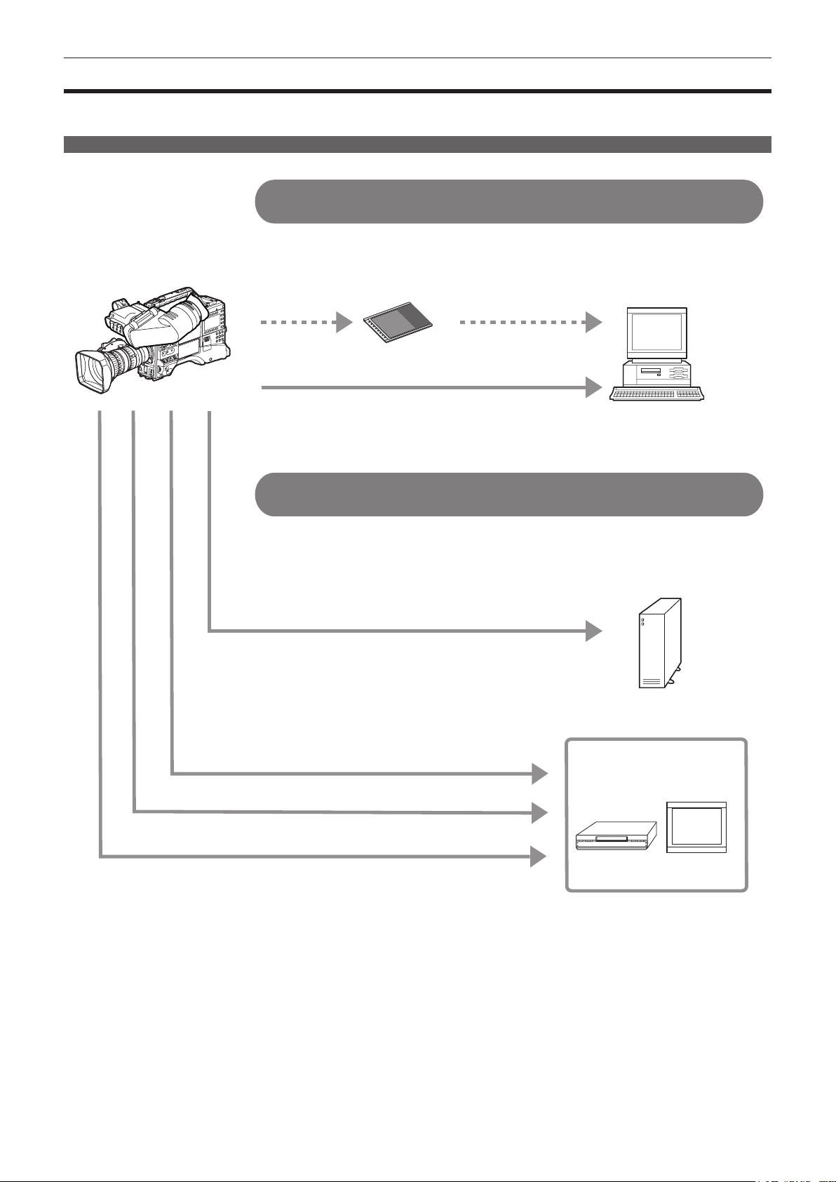
How to use the camera
The camera records to P2 cards. These large-capacity P2 cards feature outstanding transfer speeds to enable HD recording, smooth editing and
dubbing.
Editing, saving using external equipment
9LDWKH86%!WHUPLQDO
&RQQHFWLRQWRH[WHUQDOHTXLSPHQWLQ86%GHYLFHPRGH
'DWDILOHVIRUSHUIRUPLQJQRQOLQHDUHGLWLQJRQDFRPSXWHUDUH
WUDQVIHUUHG
86%GHYLFHPRGH
9LDWKH86%!WHUPLQDO
&RQQHFWLRQWRH[WHUQDOHTXLSPHQWLQ86%KRVWPRGH
7KHFDPHUDGLUHFWO\FRQWUROVWKHKDUGGLVNGULYHWRWUDQVIHUGDWD
86%KRVWPRGH
3FDUG
3HUVRQDOFRPSXWHU
([WHUQDOKDUGGLVNGULYH
%1&FDEOHFRPSRVLWH6',
+'0,FDEOH
$XGLRSLQFDEOH
*1 P2 cards and cables are optionally available. They are not supplied with the camera.
*2 The USB 2.0 cable is not supplied with the camera. Prepare a commercial USB 2.0 cable (double-shielded for noise suppression).
*3 For the BNC cable (optional) connected to the <SDI OUT/IN (OP)> and <MON OUT> terminals, prepare a double-shielded cable equivalent to 5C-FB.
*4 Prepare the HDMI cable (optional) with double or more shielded. For the HDMI cable, use of the Panasonic HDMI cable is recommended.
9LGHR
HTXLSPHQWPRQLWRU
– 16 –
Page 17
System conguration
Chapter 1 Overview — System conguration
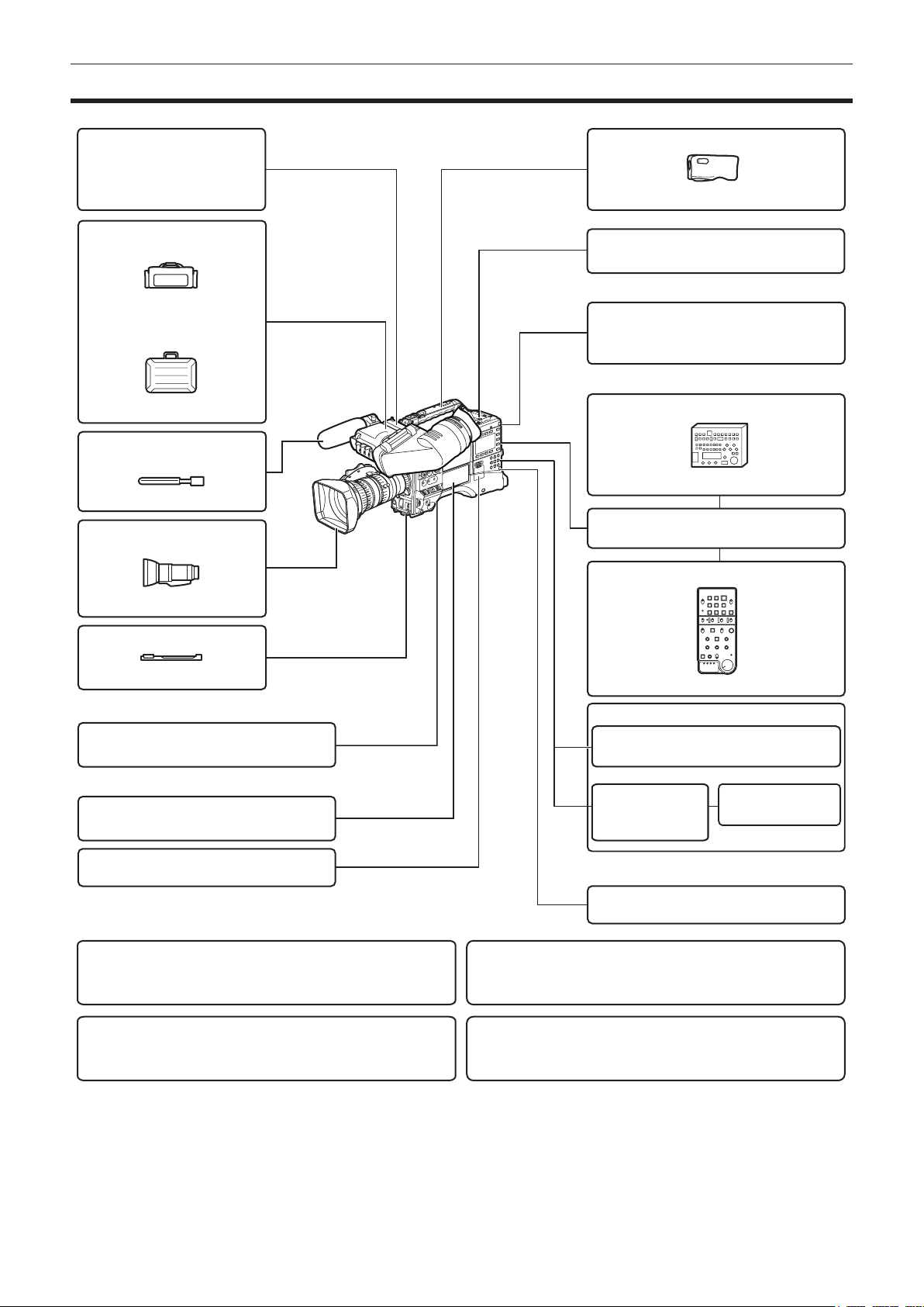
+'YLHZILQGHU
$*&9)*
$-+9).*
$-&9)*
6RIWFDUU\LQJFDVH
$-6&
+DUGFDUU\LQJFDVH
$-+7*
6KRWJXQPLFURSKRQH
3KDQWRP9
$*0&*
/HQV
%D\RQHWW\SH
$*+3;3
$*+3;(-
$*+3;(1
5DLQFRYHU
6+$15&
8QL6ORWZLUHOHVVPLFURSKRQHUHFHLYHU
/&'PRQLWRU
%7/+:
%7/+HWF
5HPRWHFRQWUROXQLW
$-5&*
5HPRWHFRQWUROFDEOH
$-&*
([WHQVLRQFRQWUROXQLW
)8-,121&$121
7ULSRGDGDSWRU
6+$170
:LUHOHVVPRGXOH
$-:0
6'PHPRU\FDUG
3FDUG
86%FRPSOLDQWGHYLFH
8SJUDGH6RIWZDUH.H\
$*6)8*
1HWZRUNIXQFWLRQH[WUDFRVWRSWLRQ
8SJUDGH6RIWZDUH.H\
$*6)8*
3URGXFWLRQSDFNH[WUDFRVWRSWLRQ
$*(&*
%DWWHU\
+<7521
',21,&+&
9PRXQWW\SH
EDWWHU\SODWH
(1'85$(
(1'85$(
([WHUQDO'&SRZHUVXSSO\
9LGHRHQFRGHUERDUG
$*<';*
+'6'6',LQSXWERDUG
$*<$*
*1 A battery holder is provided as standard on the main unit.
*2 For the latest information on P2 cards and SD memory cards not available in the Operating Instructions, visit the support desk at the following website:
http://pro-av.panasonic.net/
*3 Refer to the AJ-RC10G instruction guide on the CD-ROM provided with the camera.
*4 To use the wireless LAN function for the network function, the wireless module AJ-WM30 is required. To use the streaming function of the network function, the
video encoder board AG-YDX600G is required.
– 17 –
Page 18

Chapter 1 Overview — Accessories
Accessories
Shoulder strap (page 99)
Mount cap (already attached to the product) (page 20)
CD-ROM
f Operating Instructions
f Utility software
For installation procedures, refer to the installation manual on the CDROM.
NOTE
@@
t After unpacking the product, dispose of the packing material
properly.
– 18 –
Page 19

Chapter 2 Description of Parts
This chapter describes the names, functions, and operations of parts on
the camera. Details displayed on the [HOME] screen of SmartUI are also
described.
Page 20
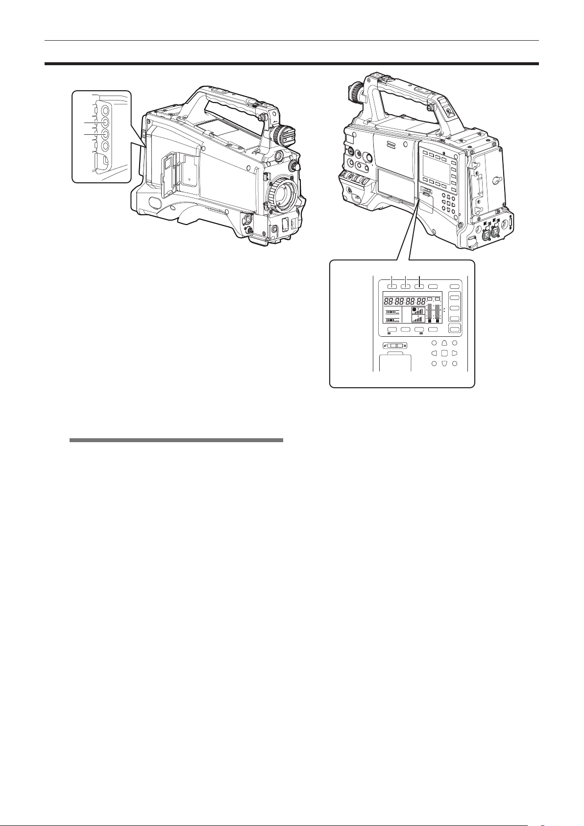
Chapter 2 Description of Parts — Power supply and accessory mounting section
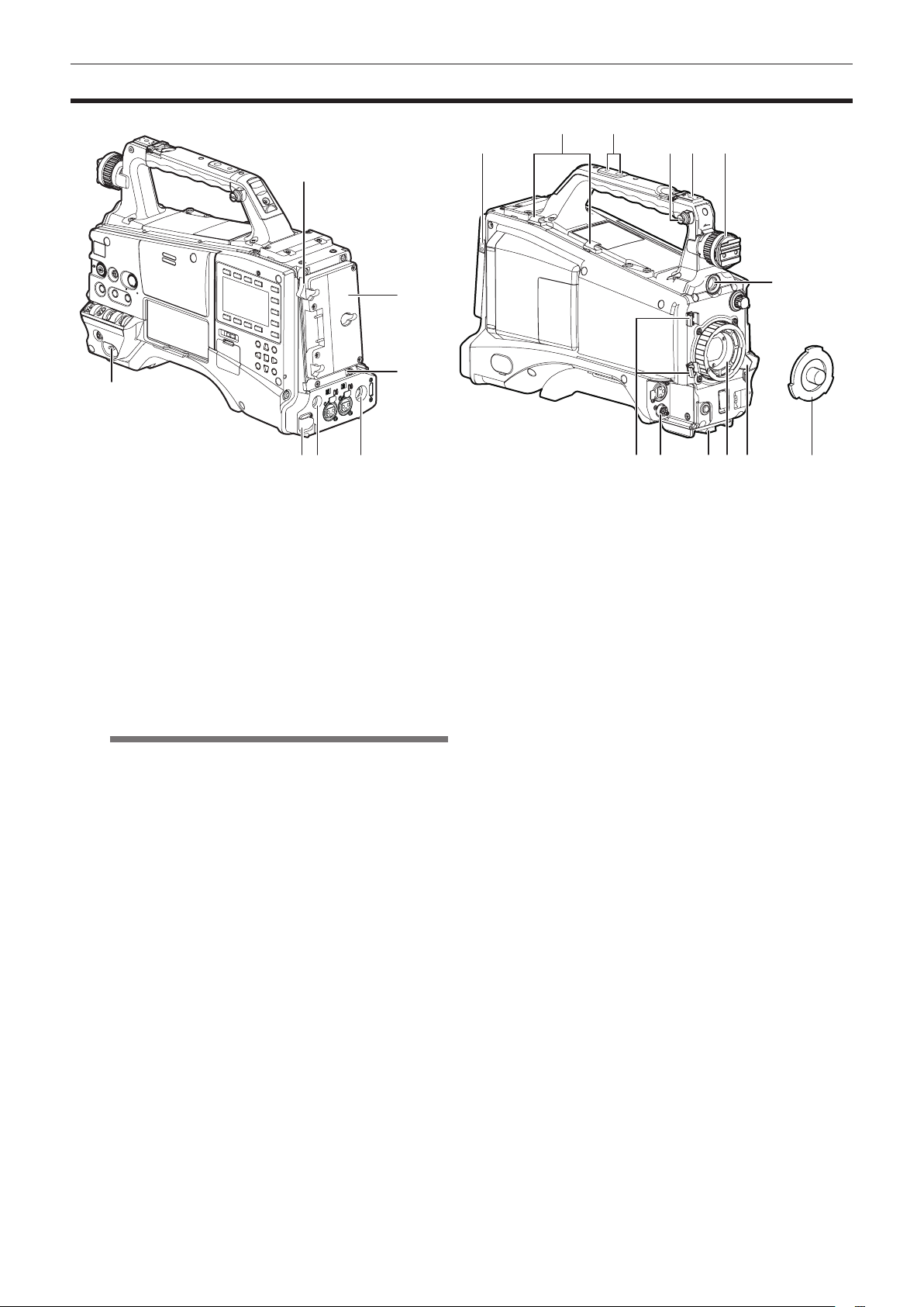
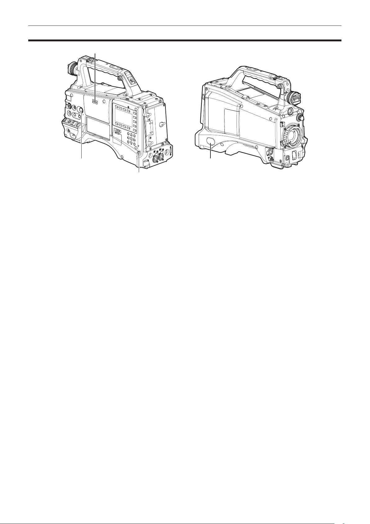
Power supply and accessory mounting section
2
1
5 6 7 2018171615
1 <POWER> switch (page 35)
Used to turn on/off the power.
2 Battery release lever (page 90)
Pull this battery release lever down to release the battery.
3 Battery holder (page 90)
Mount the Anton/Bauer battery.
4 Light control switch (page 90)
5 <DC IN> terminal (page 91)
This is the input terminal for the external power supply. Connect to the
external DC power supply.
6 <DC OUT> (DC power supply) output terminal (page 101)
This is the DC 12 V output terminal. It provides a maximum current of
1.5 A.
NOTE
@@
t When connecting external equipment to this terminal, rst fully
check the polarities of the connection. Failure to do so may
result in a malfunction.
7 <REMOTE> terminal (page 152) (page 151)
Connect the remote control unit AJ-RC10G (optional) to remotecontrol some functions.
Connect the extension control unit AG-EC4G (optional) to remotecontrol some functions.
8 Light output terminal
Connect the Anton/Bauer Ultralight 2 (optional) or an equivalent
product of 50 W or under for the video light.
The battery charge level drops sharply when the light is illuminated.
When using the light, using a battery of 90 Wh or more is
recommended.
9 Cable holders
Used for clamping the light and microphone cables in place.
10 Accessory mounting holes
Attach accessories. Do not use for purposes other than attaching
accessories.
f Mounting hole size
- 1/4-20 UNC (screw length 10 mm or shorter)
- 3/8-16 UNC (screw length 10 mm or shorter)
11 Shoulder strap ttings (page 99)
Attach the shoulder strap.
12 Light shoe
Attach the video light.
f Mounting hole size
1/4-20 UNC (screw length 6 mm or shorter)
9
10
11 128 13
3
14
4
19
13 Viewnder left/right positioning ring
To adjust the left/right position of the viewnder, loosen this ring,
and slide the viewnder to the left or right to adjust it to an easy-toview position. Tighten the ring to clamp the viewnder in place after
adjusting the viewnder.
14 <VF> terminal
Mount the viewnder AG-CVF10G (optional).
15 Lens cable/microphone cable clamp (page 93)
This clamp secures the lens and microphone cables.
16 <LENS> terminal (page 93)
Connect the lens connection cable. For a detailed description of the
lens used, refer to the Operating Instructions for the lens.
17 Tripod mount (page 99)
Attach the optional tripod adaptor (SHAN-TM700) when mounting the
camera on the tripod.
18 Lens mount (2/3-type bayonet) (page 93)
Mount the lens.
19 Lens lever (page 93)
After mounting the lens to the lens mount, tighten the lever to secure
the lens.
20 Mount cap (page 93)
Raise the lens lever to remove the cap. Replace the cap when the
lens is not mounted.
– 20 –
Page 21
Chapter 2 Description of Parts — Audio (input) function section
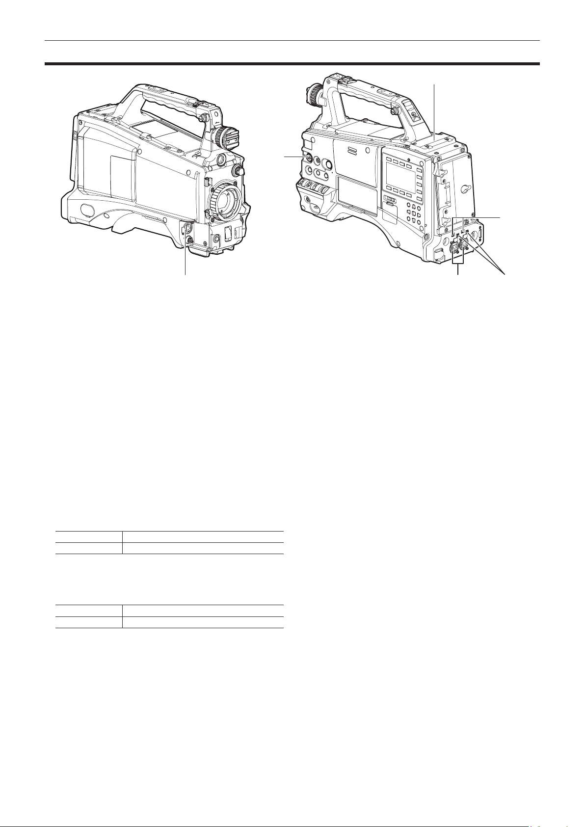
Audio (input) function section
6
2
4
1
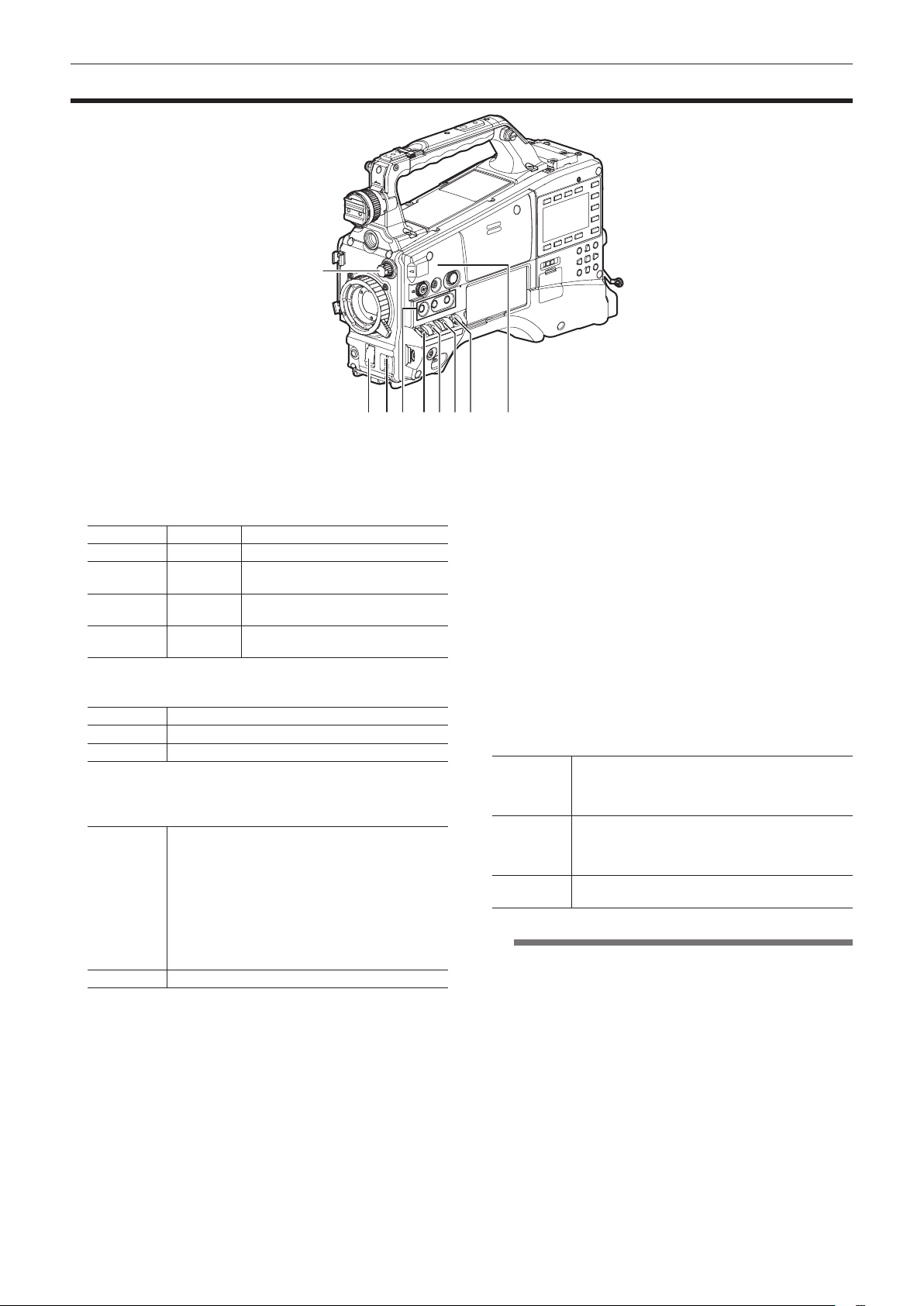
1 <MIC IN> (microphone input) terminal (page 98)
f Connect the microphone (optional).
f Can also be used for connecting the phantom microphone. When
using the phantom microphone, set the [F.MIC POWER] item on the
setting menu [AUDIO SETUP] screen to [ON].
2 <F.AUDIO LEVEL> (audio recording level adjustment) dial
(page 62)
f Adjust the recording level of audio channels 1 to 4.
f When the adjustment method for the recording level is set to
[MANU] on the [AUD02:INPUT] screen of SmartUI, the recording
level of the audio channel can be adjusted with this dial.
f Set which input terminal operation of this control works on by the
[FRONT VR CH1], [FRONT VR CH2], [FRONT VR CH3], and
[FRONT VR CH4] items on the setting menu [AUDIO SETUP]
screen.
3 <AUDIO IN CH1/3>, <AUDIO IN CH2/4> (audio input channel 1/3,
2/4) terminals (page 98)
Connect audio equipment or the microphone.
4 <LINE>/<MIC> (line input/microphone input) selector switch
(page 98)
Switch the audio input signal connected to <AUDIO IN CH1/3> and
<AUDIO IN CH2/4> (audio input channels 1/3, 2/4) terminals.
<LINE> Audio input signals from line-input audio equipment
<MIC> Audio input signal from the microphone
3 5
5 Microphone input <+48V> ON/OFF switch (page 155)
Turn on/off the power supply to the microphone connected to the
<AUDIO IN CH1/3> and <AUDIO IN CH2/4> (audio input channels
1/3, 2/4) terminals.
<+48V> Supplies +48 V power to the microphone.
<OFF> Does not supply power to the microphone.
6 Wireless slot (page 98)
Mount the UniSlot wireless receiver (optional).
– 21 –
Page 22
Chapter 2 Description of Parts — Audio (output) function section
Audio (output) function section
2
1 4
3
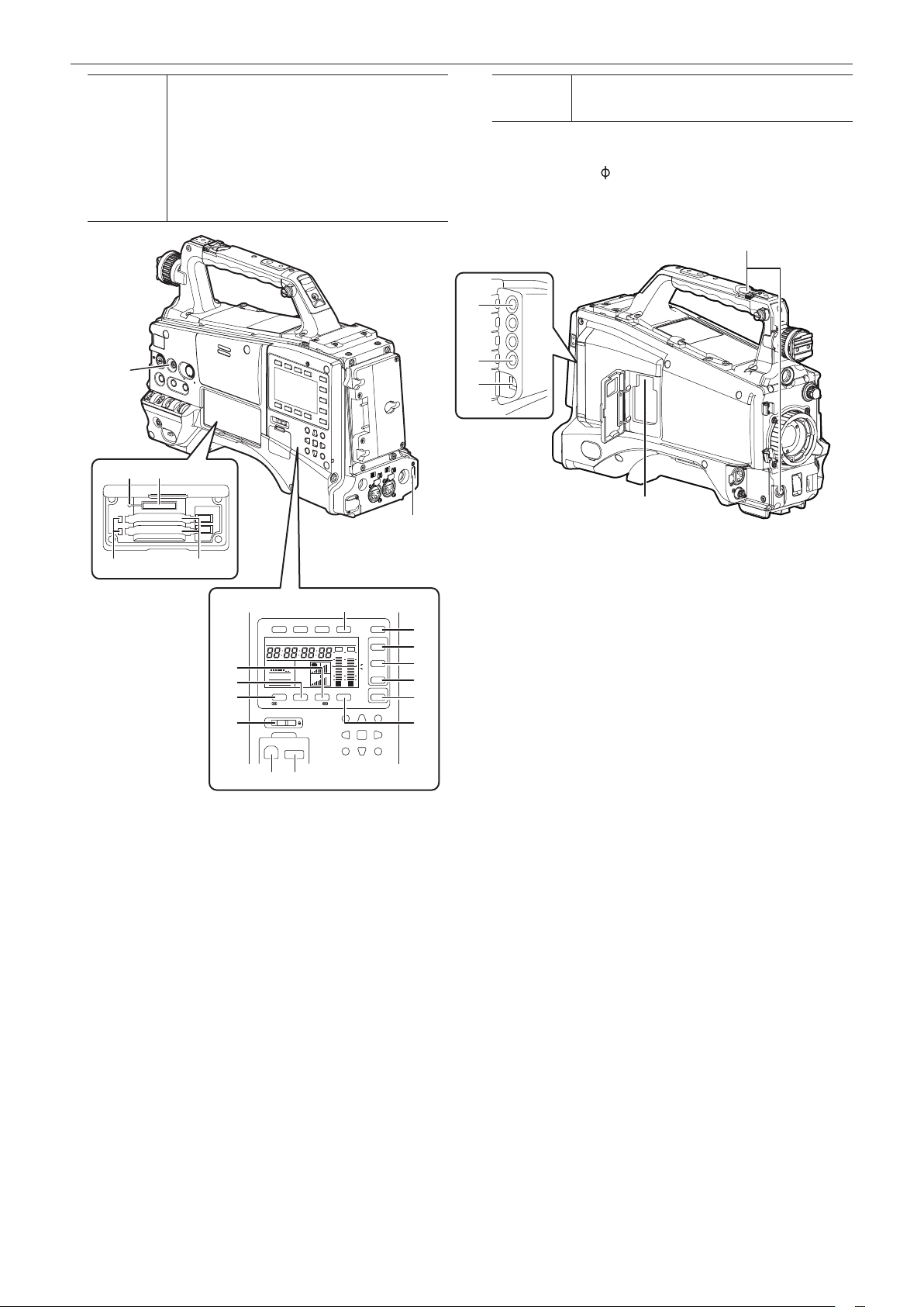
1 <MONITOR> (volume adjustment) dial
Adjust the volume of the monitor speaker and earphone.
2 Speaker
During recording, EE audio can be monitored, and during playback,
playback audio can be monitored.
Audio from the speaker is automatically turned off when an earphone
is connected to the <PHONES> terminal.
3 <PHONES> (earphone) terminal (mini jack)
This is the terminal for connecting the audio monitor earphone.
(stereo)
4 <AUDIO OUT> terminal (page 141)
f Output audio signals recorded on audio channel 1/2 or 3/4.
f Select output signals on the [AUD03:MONI] screen of SmartUI.
– 22 –
Page 23
Chapter 2 Description of Parts — Shooting and recording/playback functions section
Shooting and recording/playback functions section
1
2 5 6 7 8 93 4
r Shooting and recording (Camera unit)
1 <ND FILTER> (lter switching) dial (page 35)
Adjust the amount of light entering the MOS sensor. Used when there
is strong natural light.
Dial position Setting Description
<1> <CLEAR> The ND lter is not used.
<2> <1/4ND>
<3> <1/16ND>
<4> <1/64ND>
2 Shutter switch (page 56)
Turn on/off the electronic shutter.
<OFF> The electronic shutter is disabled.
<ON> The electronic shutter is enabled.
<SEL> The speed of the electronic shutter can be changed.
This is a spring switch. Each turn towards the <SEL> side alters the
shutter speed.
3 <AUTO W/B BAL> switch (page 53)
White balance is automatically adjusted. When this
switch is operated with the <WHITE BAL> switch on
the side set to the <A> or <B> position, adjustment is
performed in several seconds and adjustment values
<AWB>
<ABB> Black balance is automatically adjusted.
4 <USER> buttons (<USER MAIN>/<USER1>/<USER2>) (page 60)
Assign user-selected functions to each button. Pressing each button
performs the assigned function.
5 <DISP/MODE CHK> switch (page 78)
This is the spring switch to check the shooting status of the camera.
f When it is pushed towards the <OFF> side, all displays other than
the operating mode display and frame display such as area, and the
counter, marker, and safety zone on the viewnder screen turn off.
are stored in memory.
When the <WHITE BAL> switch is at the <PRST>
position, the preset color temperature can be changed
by setting the <AUTO W/B BAL> switch towards the
<AWB> side, and setting it once again towards the
<AWB> side while the color temperature is displayed.
The amount of light entering the MOS
sensor is reduced to 1/4.
The amount of light entering the MOS
sensor is reduced to 1/16.
The amount of light entering the MOS
sensor is reduced to 1/64.
f Push it towards the <CHK> side to display all information such as
the setting status of the shooting functions and functions assigned
to the <USER> buttons (<USER MAIN>/<USER1>/<USER2>) on
the viewnder screen during camera standby or shooting. While the
information is displayed, push it towards the <CHK> side again to
display the proxy and network setting status (only when the option
is installed). The mode check information display disappears after
approximately three seconds.
6 <GAIN> switch (page 53)
f Switch the video amplier gain according to the lighting conditions
under which you are shooting.
f The gain values for the <L>/<M>/<H> positions can be set by [LOW
GAIN], [MID GAIN] or [HIGH GAIN] items on the setting menu [SW
MODE] screen.
f Factory settings are L=0 dB, M=6 dB and H=12 dB.
7 <OUTPUT>/<AUTO KNEE> selector switch
Select the video signals output to the memory, viewnder and video
monitor from the camera unit.
CAM.AUTO
KNEE ON
CAM.AUTO
KNEE OFF
<BARS>
NOTE
@@
Video captured on the camera is output and the auto
knee function is activated.
Instead of the auto knee function, the dynamic range
stretcher (DRS) function can be assigned.
Video captured with the camera is output and the auto
knee function is not activated.
The knee point is xed to the level set by menu
operations.
The color bar signal is output. The auto knee function is
disabled.
t Auto knee function
Usually, when you adjust levels to shoot people or scenery
against a strongly lit background, the background will be totally
white-out, with buildings and other objects blurred. In such a
case, the auto knee function reproduces the background clearly.
The auto knee function is effective when shooting the following
scenes:
- The subject is a person positioned in the shade under a clear
sky.
- The subject is a person inside a car or a building, and you
also want to capture the background visible through a window.
- The subject is a high-contrast scene.
8 <WHITE BAL> (white balance memory selector) switch
(page 53)
Select the white balance adjustment method.
– 23 –
Page 24
Chapter 2 Description of Parts — Shooting and recording/playback functions section
<PRST>
33
27 26
Set the switch to this position when you have no time to
adjust the white balance.
f The factory setting is 3200 K.
f The color temperature can be changed successively to
3200 K, 5600 K, and the user-specied variable value
by the setting menu or by pushing the <AUTO W/B
BAL> switch towards the <AWB> side, and pushing
the <AUTO W/B BAL> switch towards the <AWB> side
again while the color temperature is displayed. The
variable value can be set at SmartUI. (page 140)
31
<A>/<B>
automatically adjusts the white balance and saves the
adjusted value to memory A or B.
You can also assign the auto tracking white balance (ATW) function to
<B> in the setting menu. (page 54)
Pressing the <AUTO W/B BAL> switch towards <AWB>
9 Focal plane index <
>
Indicates the focal plane of the MOS sensor.
It provides a reference for making accurate focal distance
measurements from the subject.
10
28
29
30
32
2425
11
13
14
12
21
HOLD COUNTER RESET MONITOR SEL
TC NDF SLAVE P -REC
MEDIA
CH1
E
E
A
F
CH2
BATT
F
/REW STOP FF/ PLAY/PAUSE
KEY LOCK
1 2
THUMBNAIL
EXIT
CANCEL BOTTOM
LIGHT
CAM
0
AUDIO
-10
-18
-20
-30
SETUP
dB
HOME
SHIFT
SET
TOP
MULTI SEL
MENU
22 23
r Shooting and recording/playback functions section (Recording
unit)
10 <REC> button (page 36)
Press this button to start recording, and press again to stop recording.
This button has the same function as the VTR button on the lens side.
11 <MONITOR SEL> button
Switch the audio channel that is output to the speaker, the
<PHONES> terminal, and the <AUDIO OUT> terminal to [CH1/2] or
[CH3/4] each time you press the button. The channel display of the
audio channel level meter is switched together.
When the screen other than the [HOME] screen of SmartUI is
displayed, the function corresponding to each setting screen is
executed.
12 <%/REW> (rewind) button
Press this button during a pause to perform fast-reverse playback.
Press it during playback to perform fast-reverse playback at
approximately 4x speed.
If it is pressed with playback paused, the clip being played back is
paused at its start point (cued state).
When the screen other than the [HOME] screen of SmartUI is
displayed, the function corresponding to each setting screen is
executed.
16
17
18
19
20
15
13 <FF/)> (fast forward) button
Press this button during a pause to perform fast playback.
Press it during playback to perform fast playback at approximately 4x
speed.
If it is pressed with playback paused, the clip being played back is
paused at the start point of the next clip (cued state).
When the screen other than the [HOME] screen of SmartUI is
displayed, the function corresponding to each setting screen is
executed.
14 <STOP> (stop) button
Press this button to stop playback.
Also press it to stop interval recording and one-shot recording, or to
end combining of clips in one-clip recording.
When the screen other than the [HOME] screen of SmartUI is
displayed, the function corresponding to each setting screen is
executed.
15 <PLAY/PAUSE> (play/pause) button
Press this button to view the playback image using the viewnder
screen or the monitor screen.
Pressing this button during playback pauses playback.
When the screen other than the [HOME] screen of SmartUI is
displayed, the function corresponding to each setting screen is
executed.
16 <LIGHT> button
Control lighting of SmartUI. Each press toggles lighting of SmartUI on
and off.
– 24 –
Page 25

Chapter 2 Description of Parts — Shooting and recording/playback functions section
17 <CAM> button (page 139)
Display the [CAMERA] screen on SmartUI.
18 <AUDIO> button (page 141)
Display the [AUDIO] screen on SmartUI.
19 <SETUP> button (page 143)
Display the [SETUP] screen on SmartUI.
20 <HOME> button (page 136)
Display the [HOME] screen on SmartUI.
21 <KEY LOCK> switch (page 136)
Disable button operations related to SmartUI and thumbnail
operations. However, <LIGHT> button operation is available.
22 <USB2.0> terminal (device) (page 146)
23 <USB2.0> terminal (host) (page 146)
Connect the USB 2.0 cable.
When the [PC MODE] item on the setting menu [PC/USB/LAN]
screen is set to [ON], data transfer using USB 2.0 is enabled.
In this state, recording/playback and clip operations on the camera
are limited.
24 P2 card insertion slot
25 P2 card access LED (page 33)
Indicate the access status of recording and playback of each card.
26 SD memory card insertion slot (page 84)
This is the insertion slot for the SD memory card (optional). Use the
SD memory card for recording/opening the setting menu and lens
les for the camera, or uploading metadata or proxy recording (extracost option), etc.
NOTE
@@
t Cautions in using SD memory cards
- On the camera, use SD memory cards that are compliant with
the SD standard or the SDHC standard.
- MMC (Multi Media Card) cannot be used. (Bear in mind that
taking pictures may no longer be possible if you do use them.)
- When using miniSD/microSD cards with the camera, always
install the adaptor specially designed for miniSD/microSD
cards. (The camera will not work properly if only the miniSD/
microSD adaptor is installed. Make sure that the card has
been inserted into the adaptor before use.)
- Use of Panasonic SD memory cards and miniSD/microSD
cards is recommended. Be sure to format cards on the
camera before use.
- Any SD memory card with a capacity of 8 MB to 2 GB and any
SDHC memory card up to 32 GB can be used on the camera.
Also, when performing proxy recording (extra-cost option), use
SDHC memory cards or SD memory cards with a capacity of
256 MB to 2 GB marked “High Speed”, etc.
- For the latest information not available in the Operating
Instructions, visit the support desk at the following website:
http://pro-av.panasonic.net/
30 <LAN> terminal (100BASE-TX)
Enabled when the network function (extra-cost option) is installed.
For the cable to be connected to the <LAN> terminal, use the
shielded cable.
31 <HDMI> terminal (page 49)
32 <USB2.0> terminal (sub-host)
Attach the wireless module AJ-WM30 (optional).
33 <FOCUS ASSIST> button (page 82)
Turn on/off the function for enlarging the video at the center of the
screen.
27 Busy (active status indication) lamp (page 85)
Indicate the active status of the SD memory card, and is illuminated
when the card is active.
NOTE
@@
t Do not insert or remove the card while the lamp is lit. This might
damage the SD memory card.
28 <SDI OUT/IN (OP)> terminal (page 49)
Output the SDI signal.
f By installing the HD/SD SDI input board (optional), SDI signals can
be input. (page 167)
29 <MON OUT> terminal (page 49)
This is the video output terminal for the monitor. Video independent
from the <SDI OUT/IN (OP)> terminal can be output. Also, HD SDI
signal or down-converted SD SDI signal, or VBS signal can be
selected on the [SET02:MON/HDMI FORMAT] screen of SmartUI.
Cross-conversion and up-conversion are not supported.
– 25 –
Page 26
Chapter 2 Description of Parts — Menu operation section and thumbnail operation section
Menu operation section and thumbnail operation section
3
21
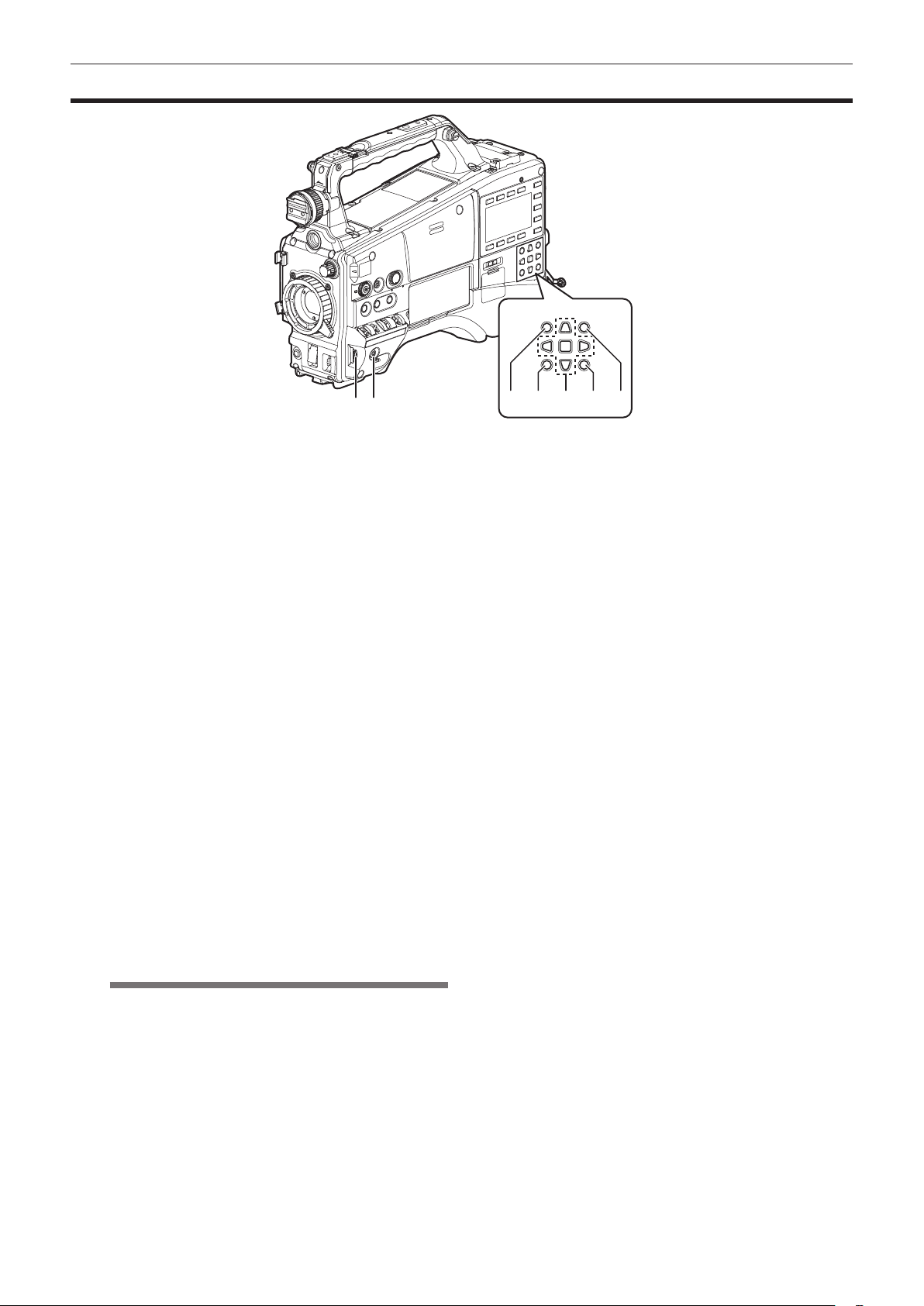
1 Jog dial button (page 118)
f With the setting menu open, navigate through setting menu pages,
select items, and set values.
f Turn the jog dial button downwards or upwards while the setting
menu is displayed to move the menu cursor downwards and
upwards, respectively. Press the jog dial button to x the settings.
f When the shutter switch is set to <ON> and synchro scan is
selected without the menu opened, the synchro scan speed can be
adjusted.
2 <MENU> button (page 118)
f Hold down this button to display the setting menu screen on the
viewnder screen. Press the button again to return to the original
image.
f Button operations are not accepted while thumbnails are displayed
or during recording.
3 <THUMBNAIL> button (page 105)
Press the button to display the thumbnail screen on the viewnder
screen and the monitor connected to the camera. Button operations
are disabled during recording and playback.
4 <EXIT>/<CANCEL> buttons (page 105)
Restore the display to the previous state while the thumbnail menu or
property screen is displayed.
Also, pressing this button with the <SHIFT> button held down makes
it function as a cancel button, which is convenient when batchcanceling clip selections.
5 Cursor/<SET> button (page 105)
Operate the setting menu, menu bars and thumbnails.
The four triangular buttons are the cursor buttons, and the square
button in the center is the <SET> button.
6 <THUMBNAIL MENU> button (page 105)
Press this button with the thumbnail displayed to move to the
thumbnail operations, allowing clip deletion operation, etc.
NOTE
@@
t Use the cursor/<SET> button and the <EXIT>/<CANCEL>
buttons to select thumbnails or operate menus. (page 105)
7 <SHIFT> button (page 105)
Press this button with other buttons held down at the same time.
f <SHIFT> button + cursor button (`/{)
This moves the pointer to the thumbnail of the clip at the start or the
end in the thumbnail screen.
f <SHIFT> button + <SET> button
Select all clips from the previously selected clip up to the clip at the
pointer position.
f <SHIFT> button + <EXIT>/<CANCEL> button
This works as the cancelation function. (page 26)
Operations with the <SHIFT> button held down are displayed at the
bottom of each button.
4 5 6 7
– 26 –
Page 27
Time code section
1
2
Chapter 2 Description of Parts — Time code section
1 <GENLOCK IN> terminal (page 69)
Input reference signals when setting the generator lock on the camera
unit, or when externally locking the time code.
NOTE
@@
t Supply Y signals of HD or or composite signals as an input
signal. However, the sub-carrier of the composite signal on the
camera cannot be externally locked.
2 <TC IN/OUT> terminal (page 63)
f Switch input/output in the menu.
f Input the reference time code to this terminal when the time code is
locked.
f Connect to the time code input terminal of the external device when
locking the time code of the external device to the time code on the
camera. (page 70)
3 <HOLD> button
The time data indication on the counter display area is retained for
the duration that this button is held down. However, the time code
generator continues to advance. Press again reactivates the counter.
This function is used to learn the time code or counter value of a
particular recorded scene.
When the screen other than the [HOME] screen of SmartUI is
displayed, the function corresponding to each setting screen is
executed.
4 <COUNTER> (counter display selector) button (page 29)
Each press of this button displays the counter value, time code, user
bits, and frame rate information on the viewnder screen.
When the screen other than the [HOME] screen of SmartUI is
displayed, the function corresponding to each setting screen is
executed.
5 <RESET> button
Reset the counter value in the time code display area to 0 (zero).
When the screen other than the [HOME] screen of SmartUI is
displayed, the function corresponding to each setting screen is
executed.
543
HOLD COUNTER RESET MONITOR SEL
TC NDF SLABE P -REC
MEDIA
CH1
A
E
F
CH2
BATT
E
F
1 2
/REW STOP FF/ PLAY/PAUSE
KEY LOCK
THUMBNAIL
CANCEL BOTTOM
LIGHT
CAM
0
AUDIO
-10
-18
-20
-30
SETUP
dB
HOME
SHIFT
SET
TOP
MULTI SEL
EXIT
MENU
– 27 –
Page 28
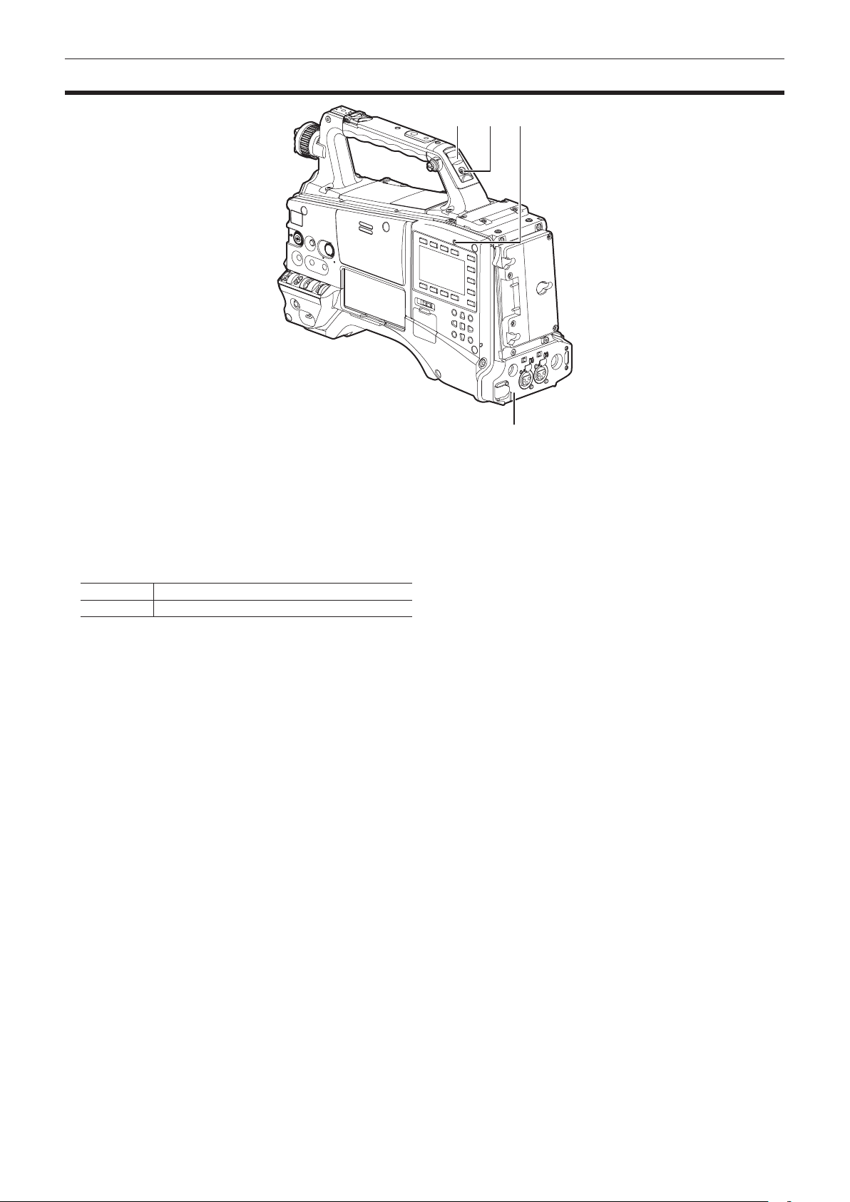
Chapter 2 Description of Parts — Warning and status display section
Warning and status display section
1 Back tally lamp
When the back tally switch is set to on, the lamp acts in the same way
as the front tally lamp at the viewnder.
2 Rear tally lamp
When the back tally switch is set to on, the lamp acts in the same way
as the back tally lamp.
3 Back tally switch
Control the action of the back and rear tally lamps.
ON The back and rear tally lamps are enabled.
OFF The back and rear tally lamps are disabled.
431
2
4 <WARNING> lamp (page 157)
Start ashing or is illuminated if something unusual occurs in the
memory.
– 28 –
Page 29
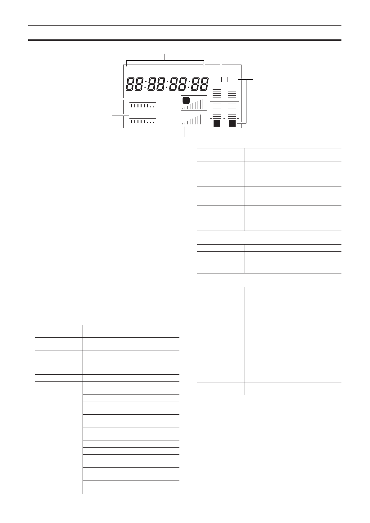
Chapter 2 Description of Parts — SmartUI display ([HOME] screen)
SmartUI display ([HOME] screen)
TC NDF SLAVE P -REC
1
2
1 Media remaining space indicator bar
Indicates the remaining free space in the P2 card using a 7-segment
display.
Each segment is equivalent to three minutes, and the decreasing
P2 card remaining time is indicated by the segments going out one
segment at a time.
2 Battery charge level indicator bar
When a battery with a digital indication (% indication) is used, all
seven segments up to the F position light if the battery charge level is
70% or higher.
When the battery charge level falls below 70%, the segments go out
one by one for each 10% drop.
3 Audio channel level meter
One segment indicates 2 dB increment, with the smallest indication
being −36 dB and the [OVER] indication displayed by ( at the
topmost position.
Each time you press the <MONITOR SEL> button, CH1/CH2, stereo,
CH3/CH4 are switched, and the channel display of the level meter is
switched together. (page 141)
Channels output to the monitor audio are displayed in white dropout.
When the stereo is selected, both channels are displayed in white
dropout.
4 Time code indications
Each time you press the <COUNTER> button, the display changes in
the order of [CLIP] → [TC] → [tc] → [UB] → [FR] → [CLIP] (viewnder
screen not displayed)* → [CLIP].
* The time code on the viewnder screen is hidden.
[CLIP]
[TC]
[tc]
[UB] Indicates the user bits value.
[FR]
Indicates the counter value in
hours:minutes:seconds.
Indicates the time code value in
hours:minutes:seconds:frames.
Indicates the time code value in
hours:minutes:seconds:frames. The frame is
displayed after converting the frame digit to 24
frames.
Indicates the information of the frame rate at
which recording is performed.
[60I] 60i interlace mode (60 elds/sec)
[60P]
[30P]
[24P]*
[24PA]* 24P advance mode (24 frames/sec)
[50I] 50i interlace mode (50 elds/sec)
[50P]
[25P]
* In the case of 24P and 24PA, the sequence
number is indicated.
60P progressive mode (60 frames/
sec)
30P progressive mode (30 frames/
sec)
24P progressive mode (24 frames/
sec)
50P progressive mode (50 frames/
sec)
25P progressive mode (25 frames/
sec)
MEDIA
E
BATT
E
F
F
4
CH1
CH2
5
3
A
1 2
6
[NDF]
[DF]
[HOLD]
[F-RUN]
[R-RUN]
[SLAVE]
5 Recording mode display
[REC] Standard recording
[P-REC] When pre-recording mode is set
[i-REC] Interval recording setting
[L-REC] Loop recording setting
6 Status information
Audio level display Indicates whether audio CH1/CH3 or CH2/CH4
Audio input Indicates the input settings of audio CH1, CH2,
At a USB connection Indicated when the [PC MODE] item on the
Error, card warning
display
Indicated when the time code is in the non-drop
frame mode.
Indicated when the time code is in the drop
frame mode.
Indicated when the time code generator/read
value is held.
Indicated when the time code is set to advance
continuously regardless of the recording
operation.
Indicated when the time code is set to advance
only during recording.
Indicated when the time code is externally
locked.
audio volume and audio level are in the auto
adjustment mode. In the auto adjustment mode,
[A] is displayed.
CH3, and CH4.
setting menu [PC/USB/LAN] screen is set to
[ON], and a device selected at [PC MODE SEL]
is connected.
f In the USB host mode: [USB
HOST CONNECTED]/[USB HOST
DISCONNECTED]
f In the USB device mode: [USB
DEVICE CONNECTED]/[USB DEVICE
DISCONNECTED]
Indicates the error code when something has
caused an error on the camera.
– 29 –
Page 30

Chapter 3 Recording and Playback
This chapter describes the basic procedure for recording and playback. It
also describes special photographic methods such as pre-recording and
interval recording.
Page 31

Chapter 3 Recording and Playback — Setting the date/time of the internal clock
OTHER FUNCTIONS
OTHER FUNCTIONS
CLOCK SETTING
PUSH MENU TO RETURN
CLOCK SETTING
Setting the date/time of the internal clock
The value of the time [CLOCK SETTING] is recorded to content (clips) and affects the thumbnail playback order. Before recording, be sure to check and
set [CLOCK SETTING] and [TIME ZONE].
The following describes the procedure for setting the date and time to September 1, 2012 and 5:20 p.m.
Set the <POWER> switch to <ON>.
1
Select the [TIME ZONE] item on the setting menu [OTHER
2
FUNCTIONS] screen, and press the jog dial button.
For details, refer to “Setting menu basic operations” (page 118).
Set the time difference from Greenwich mean time using the
3
jog dial button.
Set this by referring to the time zone table.
USER FILE
ACCESS LED
REC TALLY
CLOCK SETTING
TIME ZONE
GL PHASE
H PHASE
>>>
ON
RED
>>>
0:00
HD SDI
0
CLIPSEEK SELECT
PUSH MENU TO RETURN
r Time zone table
Time
difference
00:00 Greenwich
−00:30 +01:30
−01:00
−01:30 +02:30
−02:00
−02:30 +03:30
−03:00
−03:30
−04:00
−04:30 +05:30
−05:00
−05:30 +06:30
−06:00
−06:30 +07:30
−07:00
−07:30 +08:30
−08:00
−08:30 +09:30
−09:00
−09:30
−10:00
−10:30 +11:30
−11:00
−11:30 +12:45
−12:00
+00:30
Region Time
Azores
Mid-Atlantic
Buenos Aires
Newfoundland
Halifax
New York
Chicago
Denver
Los Angeles
Alaska
Marquesas Islands
Hawaii
Midway Islands
Kwajalein Atoll
difference
+01:00
+02:00
+03:00
+04:00
+04:30
+05:00
+06:00
+07:00
+08:00
+09:00
+10:00
+10:30
+11:00
+12:00
+13:00
Region
Central Europe
Eastern Europe
Moscow
Tehran
Abu Dhabi
Kabul
Islamabad
Bombay
Dakar
Yangon
Bangkok
Beijing
Tokyo
Darwin
Guam
Lord Howe Island
Solomon Islands
Norfolk Island
New Zealand
Chatham Islands
Select [CHANGE] at the [CLOCK SETTING] item on the
4
setting menu [OTHER FUNCTIONS] screen, and press the
jog dial button.
The [CLOCK SETTING] screen is displayed.
USER FILE
ACCESS LED
REC TALLY
CLOCK SETTING
TIME ZONE
GL PHASE
H PHASE
>>>
ON
RED
RETURN
CHANGE
HD SDI
0
CLIPSEEK SELECT
PUSH MENU TO RETURN
Turn the jog dial button to select [YEAR], and press the jog
5
dial button.
YEAR
2012
MONTH SEP
DAY 1
HOUR 13
MINUTE 7
PUSH MENU TO RETURN
Turn the jog dial button, set [YEAR] to [2012], and press the
6
jog dial button.
The year can be set from [2000] to [2037].
Turn the jog dial button to select [MONTH], and press the jog
7
dial button.
Turn the jog dial button, set [MONTH] to [SEP], and press the
8
jog dial button.
By the same operation for [YEAR]/[MONTH], set [DAY]/
9
[HOUR]/[MINUTE].
[HOUR] is displayed in the 24-hour format.
YEAR
2012
MONTH SEP
DAY 1
HOUR 17
MINUTE 20
NOTE
@@
t Clock accuracy is a lunar inequality of approximately ±30
seconds with the power off.
t When accurate time is required, check and reset the time. If
the value set to the [TIME ZONE] item on the setting menu
[OTHER FUNCTIONS] screen is changed after the time is set,
the display and recorded time changes to the time with the time
difference added.
– 31 –
Page 32

P2 card
Inserting a P2 card
Chapter 3 Recording and Playback — P2 card
NOTE
@@
t When using the camera for the rst time, be sure to set the time
data beforehand. (page 31)
Set the <POWER> switch to <ON>.
1
Open the slot cover.
2
Slot cover
Insert a P2 card into the P2 card slot.
3
f Insert the card until the eject button pops out.
f Insert the card with the logo facing up.
Eject button
Press the eject button that pops up to the right.
4
When a P2 card is inserted, the P2 card access LED for the
appropriate slot indicates the status of the P2 card. (page 33)
P2 card access LED
Close the slot cover.
5
NOTE
@@
t To prevent cards from falling out, dust from entering and reduce
the risk of exposure to static electricity, close the slot cover
before moving the camera.
t Be sure to format P2 cards only on a P2 device.
Removing a P2 card
Open the slot cover.
1
Raise the eject button.
2
Press in the eject button to remove the P2 card.
3
NOTE
@@
t After insertion, do not remove the P2 card while it is being
accessed or recognized (the P2 card access LED is ashing
orange). Doing so may result in a malfunction.
t If the P2 card is removed while being accessed, [TURN POWER
OFF] is displayed on the viewnder screen, the camera gives out
a warning indication by an alarm or <WARNING> lamp, etc. All P2
card access LEDs ash rapidly in orange, so, if this is the case,
turn off the power. (page 157)
t If the P2 card is removed while being accessed, clips on it may
become irregular. Check the clips and restore them, if required.
(page 109)
t If the P2 card being formatted is removed, formatting of the P2
card is not guaranteed. In this case, [TURN POWER OFF] is
displayed on the viewnder screen displays. Turn off the power
then back on again, and reformat the P2 card.
t If a P2 card is inserted while another card is being played back,
the inserted card is not recognized and the P2 card access LED for
that card does not light. P2 card recognition starts when playback
of the other card ends.
t Even if a P2 card is inserted in a vacant card slot during recording,
the media may not be recognized immediately in the following
instance:
- Immediately after a pre-recording
t The P2 card access LED can be set to off at all times at the
[ACCESS LED] item on the setting menu [OTHER FUNCTIONS]
screen. In this case, turn off the power before removing the card,
or, after the card is inserted or after operation (recording, playback,
etc.) has stopped, wait for the charging to complete before
removing the card.
t If thumbnails are displayed, the thumbnail screen will be canceled
when the P2 card is removed.
– 32 –
Page 33

Chapter 3 Recording and Playback — P2 card
Preventing accidental erasure
To prevent the content of a P2 card from being accidentally erased, set the write-protect switch on the P2 card to the Protect position.
NOTE
@@
t Write-protect switch can be switched while the card is being
accessed (during recording or playback), but does not take effect
until accessing of the card stops.
Write-protect switch
P2 card access LEDs and status of P2 cards
P2 card access LED P2 card status Mode check display*
Is illuminated green Recording possible Reading/writing both possible [ACTIVE]
Is illuminated orange Recording target
Flashing orange Accessing card Reading/writing are currently being performed. [ACCESSING]
Flashing orange rapidly
Flashing green slowly
Off
* The mode check is displayed on the viewnder screen. For details, refer to “Viewnder status display” (page 72).
The card is being
recognized.
Card full
Write protect
Card not supported
Format error The P2 card is not properly formatted. Reformat the card. [FORMAT ERROR]
No card
Reading/writing both possible. The card is currently
recording target (including loop recording, interval
recording, one-shot recording).
The P2 card is being recognized. [INFO READING]
There is no free space on the P2 card. The card can only
be read.
The write-protect switch on the P2 card is at the Protect
position. The card can only be read.
This card cannot be used on the camera. Replace the
card.
No P2 card is inserted. The card is waiting to be
recognized.
[ACTIVE]
[FULL]
[PROTECTED]
[NOT SUPPORTED]
[NO CARD]
P2 card recording time
r P2 cards supported on the camera
Optional P2 cards with a capacity of 4 GB to 64 GB can be used with the camera. (As of September, 2012)
NOTE
@@
t AJ-P2C002SG (2 GB) cards cannot be used.
t The driver installed on the camera may be required to be updated depending on the type of P2 card. (page 160)
t For the latest information not available in the Operating Instructions, visit the support desk at the following website:
http://pro-av.panasonic.net/
r P2 card recording times
(When a 64 GB card is used)
System mode Recording format (codec) Recording time
AVC-I 100
HD (1080i, 720P)
SD (480i)
NOTE
@@
DVCPRO HD
AVC-I 50 Approx. 128 min
DVCPRO50 Approx. 128 min
DVCPRO
DV
t The above table shows values for regular recording. With native recording, even longer recording times are available depending on the
system mode. (page 48)
t In the case of 32 GB P2 cards, the recording time becomes 1/2 of the above recording times, in the case of 16 GB P2 cards, the recording
time becomes 1/4, and in the case of 8 GB P2 cards, the recording time becomes 1/8.
t Indicated capacities include management and other area, so the space available for recording is less than the values in the table above.
Approx. 64 min
Approx. 256 min
– 33 –
Page 34

Chapter 3 Recording and Playback — P2 card
'ULYH?
Dividing clips recorded on P2 cards
If P2 cards of capacity 8 GB or greater are used on the camera, recording is automatically continued as another clip when a single continuous recording
time exceeds the times in the table below. Also, when thumbnails for clips are handled (displayed, deleted, restored, etc.) on P2 devices, they can be
handled as a single clip. Clips are sometimes displayed as separate clips in nonlinear editing software and on a computer.
Recording format (excluding native recording) Continuous recording time
AVC-I 100
DVCPRO HD
AVC-I 50
DVCPRO50
DVCPRO
DV
Approx. 5 min
Approx. 10 min
Approx. 20 min
How to handle data recorded on P2 cards
P2 cards are semiconductor memory cards that are used as the recording medium in the professional video production and broadcasting devices that
make up the DVCPRO P2 series.
f Since data recording in the DVCPRO P2 format or AVC-Intra are in a le format, they have excellent compatibility with computers. However, the le
structure is a unique format, which in addition to video and audio data in MXF les contains various other important information items. The folder
structure links the data as shown below.
&217(176
$8',2
&/,3
,&21
352;<
9,'(2
92,&(
/$67&/,37;7
$OOWKHVHIROGHUVDUHUHTXLUHG
7KLVLVWKHILOHWRZKLFKWKHLQIRUPDWLRQRIWKHILQDO
FOLSWKDWZDVUHFRUGHGZLWKWKH3GHYLFHLVZULWWHQ
NOTE
@@
t If even part of this information is modied or deleted, the data may no longer be recognized as P2 data, or the memory card may not longer
be able to be used with P2 devices.
t When transferring data from a P2 card to a computer, or when rewriting data saved on a computer back to a P2 card, to prevent data loss, be
sure to download the special “P2 Viewer” software from the following website and use the downloaded software. For details on the operating
environment required for the P2 Viewer, visit the support desk at the following website:
http://pro-av.panasonic.net/
t When using regular IT tools such as Microsoft Windows Explorer or Apple Finder to transfer data to a computer, follow the instructions below.
However, be sure to use P2 Viewer when returning data back to a P2 card.
- Transfer the corresponding CONTENTS folder and LASTCLIP.TXT le together as a set.
- Do not transfer individual les from the CONTENTS folder.
- When copying, copy the LASTCLIP.TXT le at the same time as the CONTENTS folder.
- When transferring the data in multiple P2 cards to a computer, create a folder for each P2 card to prevent clips with the same name from
being overwritten.
- Do not delete data from the P2 card.
- Be sure to format P2 cards only on a P2 device.
– 34 –
Page 35

Chapter 3 Recording and Playback — Basic procedures
Basic procedures
This section describes the basic procedures for shooting and recording. Before you actually start shooting, pre-inspect your system to see ensure that it
works properly. (page 154)
Power supply setup to P2 card insertion
Insert a charged battery pack.
1
Turn the <POWER> switch <ON>, and check the battery
2
charge level indicator on the viewfinder screen or the
[HOME] screen of SmartUI.
If the battery charge is low, replace with a fully charged battery.
NOTE
@@
t If a low battery charge level is indicated even after replacing
with a fully charged battery, make sure that the battery has
been inserted correctly. (page 130)
Insert a P2 card, make sure that the P2 card access LED is
3
illuminated orange or green, and then close the slot cover.
When two P2 cards are inserted in the P2 card slots, the P2 card with
the smaller slot number will be recorded to rst. Note, however, that
regardless of the slot number, if a P2 card is inserted later, that P2
card will not be accessed until the previously inserted P2 card has
been recorded to.
f Example: When P2 cards are inserted in two slots
If both slots contain P2 cards, the P2 cards are recorded in order
slot number 1 → 2. However, if the P2 card is slot number 1 is
removed and then re-inserted, the P2 cards will be used in the
following order: slot number 2 → 1.
Note that the recording P2 card number is held even if the power
is turned off, and when the power is next turned on, recording will
continue on the same P2 card written before powering off.
1
2
Shooting and recording switch settings
After turning on the power and inserting the P2 card, set the switches as follows before starting to use the camera.
a b dc
a: <USER MAIN> button
The [Y GET] function is assigned in the factory setting.
b: <GAIN> switch
Normally, set this to <L> (0 dB). If conditions are too dark, set gain to
an appropriate value.
c: <OUTPUT> switch
Set this switch to CAM.AUTO KNEE ON.
d: SmartUI
1 On the [SET01:TC/UB] screen, set it to [F-RUN] or [R-RUN].
2 On the [AUD02:INPUT] screen, set [LVL] to [AUTO].
For shooting
White/black balance adjustment to completion of recording
For shooting, use the following steps.
– 35 –
Page 36

Chapter 3 Recording and Playback — Basic procedures
b
a
a: <ND FILTER> dial
b: <REC> button
c: Shutter switch
d: <AUTO W/B BAL> switch
e: <WHITE BAL> switch
Select a filter by the <ND FILTER> dial according to the light
1
conditions.
Operate the <WHITE BAL> switch.
2
r When the white balance is already saved in memory:
f Set the <WHITE BAL> switch to <A> or <B>.
r When neither white or black balance is saved in memory and
you have no time to adjust the white balance:
f Set the <WHITE BAL> switch to <PRST>.
f The value can be changed to 3200 K, 5600 K, and the user-
specied variable value by pushing the <AUTO W/B BAL> switch
towards the <AWB> side, and pushing the <AUTO W/B BAL>
switch towards the <AWB> side again while the color temperature is
displayed. The variable value can be set at SmartUI. (page 140)
c db
e
r To adjust the white balance on the spot:
f Select a lter matched to the lighting conditions, set the <WHITE
BAL> switch to <A> or <B>, shoot a white test subject, and adjust
the white balance by the following steps.
1) Press the <AUTO W/B BAL> switch towards the <AWB> side to
adjust the white balance. (page 53)
2) Set the <AUTO W/B BAL> switch towards the <ABB> side to
adjust the black balance. (page 55)
3) Press the <AUTO W/B BAL> switch towards the <AWB> side to
adjust the white balance again.
Point the camera at your subject and adjust the focus and
3
zoom.
When using the electronic shutter, set the shutter speed and
4
shutter mode. (page 56)
Press the <REC> button to start recording.
5
To stop recording, press the <REC> button again.
6
NOTE
@@
t When highly bright subjects (e.g. sun or lighting) are shot, the
periphery of the subject might be colored.
Standard recording
Pressing the <REC> button starts recording of video and sound on the P2 card.
A group of data consisting of video and sound generated by a single shooting action, together with additional information, is called a “clip”.
<REC> button
NOTE
@@
t In the following cases, it may take time to complete writing to the P2 card.
Pressing the <REC> button does not accept operations immediately.
- When short-burst recording is stopped
- When stopping recording immediately after recording to two P2 cards
– 36 –
Page 37

Chapter 3 Recording and Playback — Standard recording and native recording
''
''
Standard recording and native recording
You can select between two recording methods: Native recording method that is performed with the shooting frame rate of the camera unchanged, and
the standard recording method where the frame rate is pulled down to 59.94 frames.
Standard recording (Pull-down recording)
Images at 24P are pulled down at a ratio of 2:3, and images at 30P are pulled down at a ratio of 2:2 and recorded at 59.94i or 59.94P.
24PA (2:3:3:2 advanced pull-down) is also supported.
AVC-Intra does not support pull-down recording.
&DPHUDVKRRWLQJ
32YHUL
SXOOGRZQ UHFRUGLQJ
$
$R $H %R %H %R &H &R 'H 'R 'H
%&'
&DPHUDVKRRWLQJ
32YHU3
SXOOGRZQ UHFRUGLQJ
$
$%%%&&'
$
9DOLGIUDPHV
%&'
Native recording
This recording method extracts and records valid frames at the shooting frame rates in AVC-Intra recording in 1080i, and DVCPRO HD and AVC-Intra
recording in 720P.
In the case of 720P, recording can be performed 2 to 2.5x longer than that by pull-down recording.
Even in native recording, the rate for outputting camera images and playback images is 59.94 frames that are pulled down.
&DPHUDVKRRWLQJ
31
SXOOGRZQ
5HFRUGLQJ
&DPHUDVKRRWLQJ
31
SXOOGRZQ
5HFRUGLQJ
NOTE
@@
t Recording starts from the top of a 5-frame cycle for 24P/24PA recording, 4-frame cycle for 24PN (native recording), and 2-frame cycle for
30PN (native recording) in 720P. Therefore, the time code may become non-continuous when recording clips continuously in system modes
with different recording cycles.
t Just after inserting a P2 card or turning on the power, recording is started using the internal memory of the camera. In this case, recording
cannot be stopped until the P2 card is recognized.
Push the <DISP/MODE CHK> switch towards the <CHK> side and check the P2 card status on the [SLOT1] and [SLOT2] rows displayed on
the viewnder screen.
t With 24PA (2:3:3:2 advance pull-down) compatible editing software, editing can be performed with less degradation compared with 24P (2:3
pull-down).
t When 24PA-compatible editing system is not used, shoot in the standard 24P mode.
$
$R
$H %R %H %R &H &R 'H 'R 'H
$%
$
$% %%& &'
$
$% &'
9DOLGIUDPHV
%&'
&'
%&'
– 37 –
Page 38

Chapter 3 Recording and Playback — Variable frame rate (VFR) recording function (extra-cost option)
Variable frame rate (VFR) recording function (extra-cost option)
The variable frame rate (VFR) function can be used by installing the production pack (extra-cost option) on the camera. Time-lapse (undercrank) and
high-speed (overcrank) shooting can be performed in the 1080P and 720P modes. You can select between native (PN) and standard (OVER) recording
modes.
Native variable frame rate recording
r Setting example in the 720-59.94P mode
Set the [REC FORMAT] item on the setting menu [SYSTEM
1
SETUP] screen to [AVC-I100/24PN].
For details, refer to “Setting menu basic operations” (page 118).
Set the [VFR] item on the setting menu [SCENE FILE] screen
2
to [ON], and set the [FRAME RATE] item to match your
specific shooting requirement.
Combinations of AVC-I 100, AVC-I 50, DVCPRO HD, 30PN, and 24PN can be selected as the recording format.
For details, refer to “List of recording/playback and output formats” (page 49), “[SYSTEM SETUP] screen” (page 124).
NOTE
@@
t Note the following when recording in the native variable frame rate mode:
- During recording, the P2 card to record to cannot be switched.
- Pre-recording, loop recording, interval recording, one-shot recording, and one-clip recording are not possible.
- During recording, [ON]/[OFF] setting of the [VFR] item does not change even by switching the scene le number.
- Audio cannot be recorded.*
- The time code is xed to rec-run (R-RUN).*
- The thumbnail screen is sometimes created with a one frame delay following the video currently recorded to the P2 card.
- If the exposure time acquired by operating the frame rate and shutter is 1/12 seconds or longer, images are clipped at the upper limit of the
brightness level when the exposure time is 1/12 seconds.
* Audio can be recorded when the recording mode is 24PN/25PN/30PN and the frame rate is 24/25/30 respectively. Also, the time code can be set to free-run
(F-RUN).
f It can also be set on the [CAM03:SETUP] screen of SmartUI
f The frame rate can be selected from 1 frame (1P) to 60 frames
(60P).
Press the <REC> button.
3
Recording is performed in the variable frame rate mode (native
variable frame rate).
Standard variable frame rate recording (pull-down recording)
r Setting example in the 720-59.94P mode
Set the [REC FORMAT] item on the setting menu [SYSTEM
1
SETUP] screen to [AVC-I100/60P].
For details, refer to “Setting menu basic operations” (page 118).
Set the [VFR] item on the setting menu [SCENE FILE] screen
2
to [ON], and set the [FRAME RATE] item to match your
specific shooting requirement.
AVC-I 100/60P, AVC-I 50/60P and DVCPRO HD/60P can be selected as the recording format.
For details, refer to “List of recording/playback and output formats” (page 49), “[SYSTEM SETUP] screen” (page 124).
If the frame rate is set to a low value and a fast-moving subject is shot at 60P, the image will look as if it is owing when it is played back to create an
interesting visual effect.
f It can also be set on the [CAM03:SETUP] screen of SmartUI
f The frame rate can be selected from 1 frame (1P) to 60 frames
(60P).
Press the <REC> button.
3
Recording is performed in the variable frame rate mode (Over60P).
NOTE
@@
t When the active frames are extracted by the frame rate converter, and overcrank or undercrank is set, audio can no longer be played back.
t Note the following when recording in the standard variable frame rate mode:
- During recording, the P2 card to record to cannot be switched.
- Pre-recording, loop recording, interval recording, one-shot recording, and one-clip recording are not possible.
- During recording, [ON]/[OFF] setting of the [VFR] item does not change even by switching the scene le number.
- Audio is recorded.
- If the exposure time acquired by operating the frame rate and shutter is 1/12 seconds or longer, images are clipped at the upper limit of the
brightness level when the exposure time is 1/12 seconds.
Using the variable frame rate recording function
Standard-speed shooting for lm production
With productions intended for showing on screen, the 24 fps (24 frames/second) frame rate the same as lm screening is regularly used (1x speed).
The same playback as lm screening can be achieved by setting as follows. Film like video can be achieved by progressive shooting and CINE-LIKE
Gamma.
– 38 –
Page 39

Chapter 3 Recording and Playback — Variable frame rate (VFR) recording function (extra-cost option)
r Standard settings for lm production
Setting
[SYSTEM MODE] Other item settings
[720-59.94P]
[1080-59.94i]
[1080-23.98PsF]*
*1 Only when the [REC FORMAT] item on the setting menu [SYSTEM SETUP] screen is set to [DVCPROHD/60i]
*2 Can be selected by installing the production pack (extra-cost option).
2
[REC FORMAT]
[VFR] [OFF]
[REC FORMAT]
[CAMERA MODE]*
[REC FORMAT]
1
[AVC-I100/24PN]
[AVC-I50/24PN]
[DVCPROHD/24PN]
[AVC-I100/24PN]
[AVC-I50/24PN]
[DVCPROHD/60i]
[24P]
[AVC-I100/24PN]
[AVC-I50/24PN]
Recording frame rate
24 frames
Normal speed shooting for commercials/drama production
With productions intended for screening on TV screen such as HDTV/SDTV broadcasts, a 30 fps (30 frames/second) or 25 fps (25 frames/second)
frame rate is regularly used (i.e. 1x speed). The same playback as a broadcasting station can be achieved by setting as follows. Commercials and
music videos can be recorded as lm like video and, moreover, at number of frames/second ideal for TV broadcasts.
r Standard settings for CM/drama production
Setting
[SYSTEM MODE] Other item settings
[720-59.94P]
[1080-59.94i]
[720-50P]
[1080-50i]
* Only when the [REC FORMAT] item on the setting menu [SYSTEM SETUP] screen is set to [DVCPROHD/60i] or [DVCPROHD/50i]
[REC FORMAT]
[VFR] [OFF]
[REC FORMAT]
[CAMERA MODE]* [30P]
[REC FORMAT]
[VFR] [OFF]
[REC FORMAT]
[CAMERA MODE]* [25P]
[AVC-I100/30PN]
[AVC-I50/30PN]
[DVCPROHD/30PN]
[AVC-I100/30PN]
[AVC-I50/30PN]
[DVCPROHD/60i]
[AVC-I100/25PN]
[AVC-I50/25PN]
[DVCPROHD/25PN]
[AVC-I100/25PN]
[AVC-I50/25PN]
[DVCPROHD/50i]
Recording frame rate
30 frames
25 frames
Undercrank shooting
This is a quick motion effect that can be applied to scenes showing the ow of clouds, people standing in the middle of crowds, and kung fu, etc. For
example, when shooting in recording format 24P for specifying the playback frame, a 2x speed quick motion effect can be obtained by setting the
variable frame rate to 12 fps.
r Standard settings for undercrank shooting
Setting
[SYSTEM MODE] [REC FORMAT] [VFR] [FRAME RATE]
[720-59.94P]
[1080-59.94i]
[720-50P]
[1080-50i]
[AVC-I100/24PN]
[AVC-I50/24PN]
[DVCPROHD/24PN]
[AVC-I100/24PN]
[AVC-I50/24PN]
[AVC-I100/25PN]
[AVC-I50/25PN]
[DVCPROHD/25PN]
[AVC-I100/25PN]
[AVC-I50/25PN]
[ON] Set to [22FRAME] or less. 1 to 22 frames
[ON] Set to [24FRAME] or less. 1 to 24 frames
f Even if recording is not performed in the Native recording mode, Quick motion effects can be obtained by processing recorded video on a nonlinear
editing system.
f [VFR] cannot be set if [SYSTEM MODE] is set to [1080-23.98PsF].
Recording frame rate
– 39 –
Page 40

Chapter 3 Recording and Playback — Variable frame rate (VFR) recording function (extra-cost option)
Overcrank shooting
This is a slow motion effect that can be applied to scenes such as car chases, action, climaxes, etc. For example, when recording in recording format
24P for specifying the playback frame, a 2.5x speed slow motion effect can be obtained by setting the recording frame rate to 60 fps. 720P progressive
images are smooth and provide a high-quality slow motion effect.
r Standard settings for overcrank shooting
Setting
[SYSTEM MODE] [REC FORMAT] [VFR] [FRAME RATE]
[720-59.94P]
[1080-59.94i]
[720-50P]
[AVC-I100/24PN]
[AVC-I50/24PN]
[DVCPROHD/24PN]
[AVC-I100/24PN]
[AVC-I50/24PN]
[AVC-I100/25PN]
[AVC-I50/25PN]
[DVCPROHD/25PN]
[ON] Set to [25FRAME] or more.
[ON] Set to [26FRAME] or more. 26 to 50 frames
Recording frame rate
25 to 60 frames
25 to 30 frames
f Even if recording is not performed in the Native recording mode, slow motion effects can be obtained by processing recorded video on a nonlinear
recording system.
f [VFR] cannot be set if [SYSTEM MODE] is set to [1080-23.98PsF].
– 40 –
Page 41

Chapter 3 Recording and Playback — Special recording functions
2SHUDWLRQWRVWDUWUHFRUGLQJ 2SHUDWLRQWRVWRSUHFRUGLQJ
IUDPHUHFRUGLQJ IUDPHUHFRUGLQJ IUDPHUHFRUGLQJ
Special recording functions
When recording to P2 cards, the special recording functions of pre-recording, interval recording, one-shot recording, loop recording, and one-clip
recording can be performed by setting on the setting menu [RECORDING SETUP] screen.
Pre-recording and one-clip recording can be performed in all recording modes, excluding when [VFR] is set to [ON].
Interval recording, one-shot recording and loop recording can be used only in the following setting combinations.
[SYSTEM MODE] [REC FORMAT] [CAMERA MODE] [VFR]
[1080-59.94i]
[720-59.94P]
[480-59.94i]
[1080-50i]
[720-50P]
[576-50i]
[AVC-I100/60i]
[AVC-I50/60i]
[DVCPROHD/60i] [60i] or [30P]
[DVCPROHD/60P]
[AVC-I100/60P]
[AVC-I50/60P]
[DVCPRO50/60i]
[DVCPRO/60i]
[DV/60i]
[AVC-I100/50i]
[AVC-I50/50i]
[DVCPROHD/50i]
[DVCPROHD/50P]
[AVC-I100/50P]
[AVC-I50/50P]
[DVCPRO50/50i]
[DVCPRO/50i]
[DV/50i]
—
[OFF]
—
[60i] or [30P] —
—
[OFF]
—
-— —
Pre-recording
This function enables recording of video and audio from a xed amount of time (approx. three seconds in HD recording and approx. seven seconds in
SD recording) before recording is actually started.
7LPH
$FWXDOUHFRUGLQJWLPH
3UHUHFRUGLQJWLPH
Check the settings for each item on the setting menu
1
[SYSTEM SETUP] screen.
For details, refer to “Special recording functions” (page 41).
For details on menu operations, refer to “Setting menu basic
operations” (page 118).
Set the [PREREC MODE] item on the setting menu
2
[RECORDING SETUP] screen to [ON].
The following is displayed in the special recording display area of the
viewnder screen (page 77):
Recording in progress P-REC illuminated
Paused P-PAUSE illuminated
Press the <REC> button.
3
Video and audio from the xed amount of time is recorded,
f In the following instances, pre-recording is invalid and recording
begins from the moment that each operation is performed:
- When the recording format is switched
- When playback moves to recording
- At interval recording
- At one-shot recording
- At loop recording
f Video and audio from the specic amount of time cannot be
recorded even if recording is started immediately after the thumbnail
display or playback is switched to camera video, the power is turned
on, or the [PREREC MODE] item is changed.
Interval recording
This function enables recording of single frames at the time interval set at the [INTERVAL TIME] item.
>,17(59$/7,0(@SUHVHWWLPH >,17(59$/7,0(@SUHVHWWLPH
Check the settings for each item on the setting menu
1
3
[SYSTEM SETUP] screen.
For details, refer to “Special recording functions” (page 41).
For details on menu operations, refer to “Setting menu basic
operations” (page 118).
Set the [REC FUNCTION] item on the setting menu
2
[RECORDING SETUP] screen to [INTERVAL].
4
– 41 –
7LPH
Set the time at the [INTERVAL TIME] item on the setting
menu [RECORDING SETUP] screen.
Press the <REC> button.
f The single-frame recording operation is repeated at the time interval
set at the [INTERVAL TIME] item.
Page 42

Chapter 3 Recording and Playback — Special recording functions
VWFDUG QGFDUG
f To stop recording, press the <HOME> button to display the [HOME]
screen of SmartUI, and press the <STOP> button.
Recording cannot be stopped on screens other than [HOME],
because the function other than stop function is assigned to the
<STOP> button.
f To clear settings, either turn off the power or set to [NORMAL] at the
setting menu [REC FUNCTION] item.
f The setting should be as follows at the left of the operating mode
display:
- Recording: I-REC illuminated
One-shot recording
This function performs recording once only for the preset time.
- Paused: I-PAUSE illuminated
Note, however, that when the setting in step
seconds, recording in progress I-REC ashes according to the
preset time.
- Stopped: I- of I-PAUSE ashing
NOTE
@@
t The pre-recording and one-clip recording are disabled.
t Audio is not recorded.
t Data recorded in this mode (data until the <STOP> button is
pressed) is grouped together into a single le.
3 is less than two
Check the settings for each item on the setting menu
1
[SYSTEM SETUP] screen.
For details, refer to “Special recording functions” (page 41).
For details on menu operations, refer to “Setting menu basic
operations” (page 118).
Set the [REC FUNCTION] item on the setting menu
2
[RECORDING SETUP] screen to [ONE SHOT].
Set the time at the [ONE SHOT TIME] item on the setting
3
menu [RECORDING SETUP] screen.
Press the <REC> button.
4
f Recording is performed for the time preset in step 3, after which
recording is paused.
f To stop recording, press the <HOME> button to display the [HOME]
screen of SmartUI, and press the <STOP> button.
Recording cannot be stopped on screens other than [HOME],
because the function other than stop function is assigned to the
<STOP> button.
f To clear settings, either turn off the power or set to [NORMAL] at the
setting menu [REC FUNCTION] item.
f The setting should be as follows at the left of the operating mode
display:
- Recording: I-REC illuminated
- Paused: I-PAUSE illuminated
- Stopped: I- of I-PAUSE ashing
NOTE
@@
t While this function is enabled, other operations are not
accepted.
t The pre-recording and one-clip recording are disabled.
t Audio is not recorded.
t Data recorded in this mode (data until the <STOP> button is
pressed) is grouped together into a single le.
t Acceptance of other recording operations sometimes slows
down when recording is continued by one-shot recording.
Loop recording
f This function successively records to two P2 cards inserted in the P2 card slots.
f When there is no more free space on the card, recording returns to the rst card, and recording is continued while erasing existing data already saved
on that card.
For details, refer to “Dividing clips recorded on P2 cards” (page 34).
%HIRUHORRSUHFRUGLQJVWDUWV
1RUHFRUGHGFRQWHQW &RQWHQWUHFRUGHG
6WDUWUHFRUGLQJ
5HFRUGLQJF\FOH
5HFRUGLQJF\FOH
Check the settings for each item on the setting menu
1
[SYSTEM SETUP] screen.
For details, refer to “Special recording functions” (page 41).
For details on menu operations, refer to “Setting menu basic
operations” (page 118).
Set the [REC FUNCTION] item on the setting menu
2
[RECORDING SETUP] screen to [LOOP].
Press the <REC> button.
3
f Recording is started.
f To stop recording, press the <REC> button.
f To clear settings, either turn off the power or set to [NORMAL] at the
setting menu [REC FUNCTION] item.
f The setting should be as follows at the left of the operating mode
display:
- Recording: L-REC illuminated
- Stopped: L-PAUSE illuminated
- Little free space left: P2 LACK L- ashing
BA
BC
NOTE
@@
t When this function is used, each P2 card must have at least
one minute of free space.
t When the mode check screen is switched to, the standard
recording time in accordance with the recording format is
displayed as the P2 card remaining space. When loop recording
is stopped immediately after an old recording is erased, the time
recorded on the card is sometimes less than the indicated time.
t The pre-recording and one-clip recording are disabled.
t It may take time for recording to stop. The subsequent operation
is not accepted until the P2 card access LED stops ashing and
stays illuminated.
t During loop recording, all P2 card access LEDs on the P2 cards
used for recording are illuminated or ash orange. Note that
loop recording stops when these P2 cards are removed.
t Loop recording may stop when the input reference signal of the
generator lock is disrupted during loop recording.
– 42 –
Page 43

Chapter 3 Recording and Playback — Special recording functions
One-clip recording
This function allows multiple recordings into a combined clip and does not isolate single recording (from recording start to stop).
5HFRUGLQJVWDUW
VWUHFRUGLQJ QGUHFRUGLQJ QWKUHFRUGLQJ
5HFRUGLQJVWRS 5HFRUGLQJVWRS 5HFRUGLQJVWRS
8SWRUHFRUGLQJVFDQEHFRPELQHG:KHQWKHWKUHFRUGLQJHQGVUHFRUGLQJVDUHQRORQJHU
DXWRPDWLFDOO\FRPELQHGLQWRWKHVDPHFOLSDQGVXEVHTXHQWUHFRUGLQJVWDUWVDVDQHZFOLS
To use this function, set the [ONE CLIP REC] item on the [RECORDING SETUP] screen to [ON] by menu operations.
When the one-clip recording mode is selected, [1-CLIP] is displayed at the top of the viewnder screen.
Pressing the <REC> button on the camera starts the rst recording, and [START"1CLIP] is displayed.
Subsequent recordings are automatically combined into the clip. Up to 99 recordings can be combined into a single clip.
5HFRUGLQJVWDUW 5HFRUGLQJVWDUW
6LQJOHFRPELQHGFOLS
Recording a new clip
Follow the instructions below to use a new and separate clip, and end combining to the clip.
f While recording is paused, press the <HOME> button to display the [HOME] screen on SmartUI, and press the <STOP> button for two seconds or
longer. (When operating while recording is on standby)
On screens other than [HOME], the function other than stop function is assigned to the <STOP> button.
f Press and hold the <REC> button for approximately two seconds during recording to end recording. (When operating during recording)
Follow the instructions above to end combining to the clip. [END 1-CLIP] is displayed, and subsequent recordings are made to a new and separate clip.
NOTE
@@
t In addition to the above steps, recordings are no longer automatically combined into the same clip and subsequent recording are combined
into a new clip in the following instances:
- When the power is turned off
- When the P2 card with the previous recording is removed
- When the P2 card is formatted or the clip is deleted (when the previous combined lip does not exist)
t Combining to a clip does not end even by pressing the <STOP> button in the menu or in the thumbnail display.
t Combining to a clip cannot be stopped even by pressing the <STOP> or <REC> button on the remote control unit (AJ-RC10G) and on the
extension control unit (AG-EC4G).
Exiting the one-clip recording mode
Set the [ONE CLIP REC] item to [OFF] by menu operations.
Cueing to the start of the combined section of a clip
A text memo can be automatically attached to the start of the recording, the start of a section can be cued for playback, and the thumbnail of the location
can be checked before each recording.
To automatically attach a text memo at the start of recording, set the [START TEXT MEMO] item on the [RECORDING SETUP] screen to [ON] by menu
operations.
To check and play back the location of the attached text memo, select [THUMBNAIL] → [TEXT MEMO CLIPS] from the thumbnail menu and move the
cursor over the desired clip.
For details, refer to “Playing back from the text memo position” (page 108).
Also, to cue the location of the text memo for playback, set the [SEEK SELECT] item on the [OTHER FUNCTIONS] screen to [CLIP&T], and press the
<FF/)> or <%/REW> button while playback is paused.
Proxy recording (extra-cost option) in the one-clip recording mode
Proxy recording is possible even in the one-clip recording mode.
Since proxy data is also grouped together in the same way as a combined clip, it can be handled as a single clip in a P2 viewer, for example. However,
note the following when recording the proxy data to SD memory cards.
f When the SD memory card is removed and replaced while combining of clips is in progress, proxy recording is not performed to the SD memory card
until combining of subsequent clips ends. Check available space and the number of the les (maximum 1000 clips) before using the card. To continue
proxy recording after the SD memory card has been replaced midway, hold down the <STOP> button for approximately two seconds to end combining
of clips and start recording as a new clip.
f The proxy data on the SD memory card to which recording was stopped midway will not match the data of the clip recorded on the P2 card and will be
incomplete.
Notes on the one-clip recording mode
f The one-clip recording mode is disabled when interval recording, one-shot recording, loop recording, and variable frame rate recording functions are
selected.
– 43 –
Page 44

Chapter 3 Recording and Playback — Special recording functions
f Menu and thumbnail operations are restricted as follows when combining to the clip is in progress. Press the <STOP> button for approximately two
seconds to stop combining to the clip, and try the operations again.
- The following setting menus cannot be changed.
[SYSTEM MODE], [REC SIGNAL], [CAMERA MODE], [REC FORMAT], [PC MODE], [REC FUNCTION], [25M REC CH SEL]
NOTE
@@
t The [VFR] item can be changed to “ON” by the jog dial or menu even while combining to the clip is in progress. In this case, combining of
the clip ends, and subsequent recordings are made to separate clips each time.
f The following menu items relating to reading/writing of the SD memory card and reading of setting les cannot be executed:
- [LOAD/SAVE/INIT] item on the [SCENE FILE] screen
- Each item on the [CARD FUNCTIONS] screen
- [CAC CARD READ] item on the [LENS SETUP] screen
- [USER FILE] and [MENU INIT] items on the [OTHER FUNCTIONS] screen
f The following thumbnail menu items cannot be selected and executed:
[OPERATION] → [COPY]
f To enable combining of the clip at the next recording, end processing of recording may take slightly longer than standard recording.
f Fade processing on non-continuous audio is not made at combining of recordings in clips at playback.
f When clips containing many clip combinations are used in nonlinear editing software, operation of the clip may not be normal depending of the type of
software. (As of September, 2012)
For the latest information on software whose operation has been veried, visit the support desk at the following website:
http://pro-av.panasonic.net/
Proxy recording function (extra-cost option)
By installing the video encoder board (extra-cost option), video recordings in MPEG4 or H.264 format and real-time data such as time code data can be
recorded to the P2 card and SD memory card simultaneously in addition to the video and audio of the materials recorded on the camera.
For details, refer to “Video encoder board (AG-YDX600G)” (page 162).
Hot swap recording
When P2 cards are inserted into two P2 card slots, recording can be performed continuously across two cards.
Also, the card other than the one currently being recorded to can be swapped and recording can be continued on two or more cards. (hot swap
recording function)
Note, however, P2 card recognition might slow down depending on the timing (immediately after pre-recording or before and after continuous recording
across two card slots) that the P2 card is inserted into the vacant card slot. When inserting a P2 card, make sure that there is at least one minute of free
space on the card to be recorded to.
NOTE
@@
t Hot swap playback is not supported.
Rec review function
f After recording ends, pressing the <RET> button on the lens automatically cues to approximately the last two seconds of video just recorded. The
playback time can be increased up to ten seconds by holding down the <RET> button on the lens.
In this way, you can check whether or not video has been recorded properly. After playback, the camera is again ready to start recording. For short
clips, however, when the start of the clip is cued to, holding down the <RET> button does not play back any clips before the current clip.
f The rec review function can be assigned to each of the <USER> buttons (<USER MAIN>/<USER1>/<USER2>) at the [USER MAIN], [USER1], and
[USER2] items on the setting menu [SW MODE] screen.
NOTE
@@
t Note that when a backup device is connected to the <SDI OUT/IN (OP)> terminal, etc., and the backup image is being recorded, the
playback image currently in use by the recording review function will be recorded.
t In the one-clip recording mode, the furthest rewind point using rec review and the playback start point after pausing recording is not at the
start of the clip, but at the start of the most recent recording.
Shot mark recording function
Shot mark is the mark added to the thumbnail of each clip to distinguish that clip from others.
Only clips with shot marks attached can be displayed or played back.
Adding shot marks
Assign shot marks to the desired <USER> buttons (<USER
1
MAIN>/<USER1>/<USER2>) or the <RET> button on the lens
on the setting menu [SW MODE] screen.
For details, refer to “Setting menu basic operations” (page 118).
During recording or a pause after recording, press the
2
button to which the shot mark is assigned (the <USER>
buttons (<USER MAIN>/<USER1>/<USER2>) or the <RET>
button on the lens).
f [SHOT MARK ON] is displayed, and the short mark is added to the
clip currently being recorded.
f Another press of the button displays [SHOT MARK OFF] and the
shot mark disappears.
NOTE
@@
t When the shot mark is added during a recording pause, it is added
to the clip recorded immediately before.
t Shot marks can also be added while the thumbnail display is
active.
t Shot marks cannot be added in loop recording, interval recording
and one-shot recording. If an operation is invalid, [SHOT MARK
INVALID] is displayed when the button is pressed.
– 44 –
Page 45

Chapter 3 Recording and Playback — Special recording functions
t During playback, setting or canceling the shot mark is not
available, but while pausing the playback, setting or canceling the
shot mark is available.
t When video data obtained by a single shooting session by hot
swap recording comprises multiple clips, the shot mark can be
set or deleted only if all P2 cards containing that video data are
inserted in the card slots. Also, with video data comprising multiple
clips like this, the shot mark can be added to the top clip only.
Text memo recording function
Text memos can be added to any video point while a clip is being recorded or played back.
Only clips with a text memo added can be selected and displayed as thumbnails, thumbnails and time codes at text memo positions can be displayed
and played back from text memo points, and only required positions can be selected and copied. (page 107)
Adding text memos
Assign text memos to the desired <USER> buttons (<USER
1
MAIN>/<USER1>/<USER2>) or the <RET> button on the lens
on the setting menu [SW MODE] screen.
For details, refer to “Setting menu basic operations” (page 118).
During recording or a pause after recording, press the
2
button to which the text memo is assigned (the <USER>
buttons (<USER MAIN>/<USER1>/<USER2>) or the <RET>
button on the lens).
[TEXT MEMO] is displayed, and the text memo is added to the video
clip that was displayed when the button was pressed.
NOTE
@@
t Up to 100 text memos can be recorded to a single clip.
t Text memos cannot be added in loop recording, interval recording
and one-shot recording. If an operation is invalid, [TEXT MEMO
INVALID] is displayed when the button is pressed.
– 45 –
Page 46

Chapter 3 Recording and Playback — Normal and variable speed playback
Normal and variable speed playback
r Normal speed playback
Color playback images can be viewed on the viewnder screen by pressing the <PLAY/PAUSE> button. Likewise, color playback images can be viewed
on a color video monitor connected to the <MON OUT>, <SDI OUT/IN (OP)>, or <HDMI> terminal.
Playback can also be paused by pressing the <PLAY/PAUSE> button during playback.
r Fast-forward and fast-reverse playback
The <FF/)> and <%/REW> buttons provide 32x and 4x fast-forward and fast-reverse playback. Pressing these buttons during a stop and playback
fast-forwards and fast-reverses at 32x and 4x speed, respectively.
r Cueing clips
If the <FF/)> button is pressed with playback paused, the clip being played back is paused at the start point of the next clip (cued state). If the <%/
REW> button is pressed with playback paused, the clip being played back is paused at the start point of the clip currently being played back (cued
state).
NOTE
@@
t When playing back or switching to the thumbnail screen immediately after removing or inserting the P2 card or the power is turned on, it may
take time to read the clip information. During this time, [UPDATING..] is displayed on the thumbnail screen.
t If a P2 card is inserted while another card is being played back, the clips on the inserted card cannot be played back. A P2 card inserted
during playback is recognized after playback ends.
t When playing back clips spread over multiple P2 cards at variable speed, audio might be instantaneously interrupted, though this is not a
malfunction.
t To play back clips in the different system mode, match the [SYSTEM MODE] item to the format of the clip and set the camera again.
t Audio of CH5 to CH8 recorded on another device cannot be played back.
– 46 –
Page 47

Chapter 4 Adjustments and Settings for
Recording
This chapter describes how to set convenient functions such as adjusting
white and black balance, adjusting shooting functions such as ash
band compensation (FBC) function, assigning functions to the <USER>
buttons (<USER MAIN>/<USER1>/<USER2>), and setting the time data.
Page 48

Chapter 4 Adjustments and Settings for Recording — Multi formats
Multi formats
Selecting recording signals
The camera records images in the format of HD (1080i, 720P) signals combining the AVC-Intra or DVCPRO HD codecs, and SD (480i/576i) signals
combining the DVCPRO50, DVCPRO, and DV codecs respectively.
Various shooting frames and recording frames (native recording) can be selected according to your specic requirements.
You can select recording and shooting signals in the following setting menus.
Setting menu screen Setting menu item Description of settings
[SYSTEM MODE]
[SYSTEM SETUP] screen
[SCENE FILE] screen
NOTE
@@
[REC SIGNAL]
[REC FORMAT]
[CAMERA MODE] Select the pull-down shooting mode when not in the native recording.
[ASPECT CONV] In the SD mode, select the video aspect ratio for recording and output.
[VFR]
[FRAME RATE]
t When the [SYSTEM MODE], [REC SIGNAL], [REC FORMAT], or [CAMERA MODE] item is changed, video or audio may be interrupted, but
this is not a malfunction.
Select the 1080i/720P/480i/576i signal format.
When this setting is changed, wait until [TURN POWER OFF] is displayed, and turn off the power
then back on again.
Can be switched between recording of shooting with the camera [CAMERA] and input recording of
the SDI signal [SDI IN] by installing the HD/SD SDI input board (extra-cost option).
Select the codec of AVC-Intra or DVCPRO HD in the HD mode, and select each codec of
DVCPRO50, DVCPRO, and DV in the SD mode. Set the shooting frame rate at the same time.
Can be switched by installing the production pack (extra-cost option). When is set to [ON],
shooting by the variable frame rate recording function is possible, and shooting and recording can
be performed according to the shooting frame rate setting of the [FRAME RATE] item.
For details, refer to “Variable frame rate (VFR) recording function (extra-cost option)” (page 38).
Can be switched by installing the production pack (extra-cost option). Set the number of frames for
variable frame rate shooting when the [VFR] item is set to [ON].
List of recording formats and recording functions
The table below shows the formats supported by the camera and recording functions.
r Recording formats and recording playback times
Recording format
64 GB
32 GB
16 GB
Capacity
1 card Approx. 64 min Approx. 128 min Approx. 64 min Approx. 128 min Approx. 256 min
2 cards Approx. 128 min Approx. 256 min Approx. 128 min Approx. 256 min Approx. 512 min
1 card Approx. 32 min Approx. 64 min Approx. 32 min Approx. 64 min Approx. 128 min
2 cards Approx. 64 min Approx. 128 min Approx. 64 min Approx. 128 min Approx. 256 min
1 card Approx. 16 min Approx. 32 min Approx. 16 min Approx. 32 min Approx. 64 min
2 cards Approx. 32 min Approx. 64 min Approx. 32 min Approx. 64 min Approx. 128 min
AVC-Intra 100 AVC-Intra 50 DVCPRO HD DVCPRO50 DVCPRO/DV
f Recording playback time becomes 1.25 times longer in 24PN native recording.
f The above times were obtained by continuous recording as a single clip. The overall recording time might be shorter than the times above depending
on the number of clips to record.
List of recording settings and recording functions
The recording modes of the camera act as follows depending on the menu settings.
Setting Recording setting (setting menu) Recording/operation enabled/disabled
Operation mode [REC SIGNAL]
Interval recording
One-shot
recording
Loop recording [LOOP]
Native variable
frame rate (VFR)
Standard variable
frame rate (VFR)
Standard recording [OFF] All formats Available Available Available
Input recording of
SDI signal
*1 This becomes valid when the production pack (extra-cost option) is installed.
*2 This becomes valid when the frame rates of [REC FORMAT] and [VFR] are the same.
[CAMERA]
[SDI IN] Disabled Disabled
[REC
FUNCTION]
[INTERVAL]
[ONE SHOT]
[NORMAL]
1
[VFR]*
Disabled Disabled
[ON]
[REC
FORMAT]
[24PN],
[30PN], [25PN]
Other than
[24PN],
[30PN], [25PN]
[60i], [50i],
[60P], [50P]
Pre-
recording
Not
available
Not
available*
Not
available
Not
available
2
One-clip
recording
Not
available
Not
available*
Not
available
Not
available
2
Proxy*
Not
available
Not
available*
Not
available
Available
1
Text memo Shot mark
Not
available
2
Available Available
Not
available
– 48 –
Page 49

Chapter 4 Adjustments and Settings for Recording — Multi formats
Selecting video output
The video output method can be selected.
Video output can be selected, for example, in the following setting menus.
Setting menu item Description of settings
[MON]
([SET02:MON/HDMI FORMAT] screen of SmartUI)
[SETUP]
([SYSTEM SETUP] screen)
[D.CON]
([SET02:MON/HDMI FORMAT] screen of SmartUI)
Select the signal method used to output to the <MON OUT> and <HDMI> terminals.
Select the setup level of the signal (composite) to output to the <MON OUT> terminal.
f [0%]: 0% setup for both output and recording
f [7.5%A]: 7.5% setup for output only (recording 0%)
The [SETUP] menu setting is valid at playback, too.
Select the screen type at down conversion output (composite and SD SDI output) in the HD
mode (1080i, 720P).
Selecting video output from each terminal
Monitor output setting
([SET02:MON/HDMI
[SYSTEM MODE]
[1080-59.94i]
[1080-23.98PsF]
(extra-cost option)
[720-59.94P]
[480-59.94i]
[1080-50i]
[720-50P]
[576-50i]
* The [MON] item and the [HDMI] item are interlocked.
FORMAT] screen of
SmartUI)*
[MON] [HDMI] <SDI OUT/IN (OP)> terminal <MON OUT> terminal <HDMI> terminal
[AUTO] [1080i/720P]
[480i] [480P] 480/59.94i (SD SDI) 480/59.94p
[VBS] [480P] 480/59.94i (VBS) 480/59.94p
[AUTO] [1080i/720P]
[480i] [480P] 480/59.94i (SD SDI) 480/59.94p
[VBS] [480P] 480/59.94i (VBS) 480/59.94p
[AUTO] [1080i/720P]
[480i] [480P] 480/59.94i (SD SDI) 480/59.94p
[VBS] [480P] 480/59.94i (VBS) 480/59.94p
[SDI] [480P]
[VBS] [480P] 480/59.94i (VBS) 480/59.94p
[AUTO] [1080i/720P]
[576i] [576P] 576/50i (SD SDI) 576/50p
[VBS] [576P] 576/50i (VBS) 576/50p
[AUTO] [1080i/720P]
[576i] [576P] 576/50i (SD SDI) 576/50p
[VBS] [576P] 576/50i (VBS) 576/50p
[SDI] [576P]
[VBS] [576P] 576/50i (VBS) 576/50p
1080-23.98PsF
1080/59.94i
720/59.94p
480/59.94i
1080/50i
720/50p
576/50i
Video output
1080/59.94i (HD SDI) 1080/59.94i
1080/59.94i (HD SDI) 1080/59.94i
720/59.94p (HD SDI) 720/59.94p
480/59.94i (SD SDI) 480/59.94p
1080/50i (HD SDI) 1080/50i
720/50p (HD SDI) 720/50p
576/50i (SD SDI) 576/50p
List of recording/playback and output formats
r Camera recording mode (when the [REC SIGNAL] item is [CAMERA])
Setting ([SYSTEM MODE] = [1080-59.94i])
[REC FORMAT]
[AVC-I100/60i]
[AVC-I50/60i]
[AVC-I100/30PN]
[AVC-I50/30PN]
[AVC-I100/24PN]
[AVC-I50/24PN]
[DVCPROHD/60i]
[CAMERA
MODE]
Disabled
[60i] 1080/60i
[30P]
[24P]
[24PA]
[VFR]
[OFF] Disabled
[FRAME
RATE]
1080/30PN Native
1080/24PN Native
1080/30P Over60i 2:2 Pull
1080/24P Over60i 2:3 Pull
1080/24PA Over60i 2:3:3:2
Pull Down
Recording format
1080/60i
Down
Down
AVC-I 100
(AVC-I 50)
DVCPRO HD
<SDI OUT/IN (OP)> terminal
Video format Audio
1080-59.94i
1080-29.97PsF
Over59.94i 2:2
1080-23.98PsF
Over59.94i 2:3
1080-59.94i
1080-29.97PsF
Over59.94i 2:2
1080-23.98PsF
Over59.94i 2:3
1080-23.98PsF
Over59.94i 2:3:3:2
4ch
4ch
– 49 –
Page 50

Chapter 4 Adjustments and Settings for Recording — Multi formats
Setting ([SYSTEM MODE] = [1080-59.94i])
[REC FORMAT]
[AVC-I100/60i]
[AVC-I50/60i]
[AVC-I100/30PN]
[AVC-I50/30PN]
[AVC-I100/24PN]
[AVC-I50/24PN]
[DVCPROHD/60i]
Setting ([SYSTEM MODE] = [1080-50i])
[REC FORMAT]
[AVC-I100/50i]
[AVC-I50/50i]
[AVC-I100/25PN]
[AVC-I50/25PN]
[DVCPROHD/50i]
[AVC-I100/50i]
[AVC-I50/50i]
[AVC-I100/25PN]
[AVC-I50/25PN]
[DVCPROHD/50i]
[CAMERA
MODE]
Disabled
[60i] [1] - [30P] 1080/60i
[30P] Disabled Not available — —
[24P] Disabled Not available — —
[24PA] Disabled Not available — —
[CAMERA
MODE]
Disabled
[50i] 1080/50i
[25P]
Disabled
[50i] [1] - [25P] 1080/50i
[25P] Disabled Not available — —
[VFR]
[ON]*
[VFR]
[OFF] Disabled
[ON]*
[FRAME
RATE]
[1] - [30P]
[FRAME
RATE]
[1] - [25P]
<SDI OUT/IN (OP)> terminal
Recording format
1080/60i
1080/30PN Native VFR
(At 30P: 30PN Native audio
recordable)
1080/24PN Native VFR
(At 24P: 24PN Native audio
recordable)
Recording format
1080/50i
1080/25PN Native 1080-25PsF Over50i 2:2
1080/25P Over50i 2:2 Pull
Down
1080/50i
1080/24PN Native VFR
(At 25P: 25PN Native audio
recordable)
AVC-I 100
(AVC-I 50)
DVCPRO
HD
AVC-I 100
(AVC-I 50)
DVCPRO HD
AVC-I 100
(AVC-I 50)
DVCPRO HD
Video format Audio
1080-59.94i VFR
1080-59.94i VFR 4ch
<SDI OUT/IN (OP)> terminal
Video format Audio
1080-50i
1080-50i
1080-25PsF Over50i 2:2
1080-50i VFR
1080-50i VFR 4ch
4ch
Mute
(At 30P: 4ch
available)
Mute
(At 24P: 4ch
available)
4ch
4ch
4ch
Mute
(At 25P: 4ch
available)
Setting ([SYSTEM MODE] = [1080-23.98PsF]*)
[REC FORMAT]
[AVC-I100/24PN]
[AVC-I50/24PN]
Setting ([SYSTEM MODE] = [720-59.94P])
[REC FORMAT]
[AVC-I100/60P]
[AVC-I50/60P]
[AVC-I100/30PN]
[AVC-I50/30PN]
[AVC-I100/24PN]
[AVC-I50/24PN]
[DVCPROHD/60P] 720/60P
[DVCPROHD/30PN] 720/30PN Native
[DVCPROHD/24PN] 720/24PN Native
[CAMERA
MODE]
Disabled Disabled Disabled 1080/24PN Native
[CAMERA
MODE]
Disabled [OFF] Disabled
[VFR]
[VFR]
[FRAME
RATE]
[FRAME
RATE]
Recording format
Recording format
720/60P
720/30PN Native
720/24PN Native
AVC-I 100
(AVC-I 50)
AVC-I 100
(AVC-I 50)
DVCPRO HD
<SDI OUT/IN (OP)> terminal
Video format Audio
1080-23.98PsF
Over47.96i 2:2
<SDI OUT/IN (OP)> terminal
Video format Audio
720-59.94P 4ch
720-29.97P Over59.94P
2:2
720-23.98P Over59.94P
2:3
720-59.94P
720-59.94P VFR
720-29.97P Over59.94P
2:2
720-23.98P Over59.94P
2:3
4ch
4ch
4ch
4ch
4ch
– 50 –
Page 51

Chapter 4 Adjustments and Settings for Recording — Multi formats
Setting ([SYSTEM MODE] = [720-59.94P])
[REC FORMAT]
[AVC-I100/60P]
[AVC-I50/60P]
[AVC-I100/30PN]
[AVC-I50/30PN]
[AVC-I100/24PN]
[AVC-I50/24PN]
[DVCPROHD/60P]
[DVCPROHD/30PN]
[DVCPROHD/24PN]
Setting ([SYSTEM MODE] = [720-50P])
[REC FORMAT]
[AVC-I100/50P]
[AVC-I50/50P]
[AVC-I100/25PN]
[AVC-I50/25PN]
[DVCPROHD/50P] 720/50P
[DVCPROHD/25PN]
[AVC-I100/60P]
[AVC-I50/60P]
[AVC-I100/25PN]
[AVC-I50/25PN]
[DVCPROHD/50P]
[DVCPROHD/25PN]
[CAMERA
MODE]
Disabled [ON]* [1] - [60P]
[CAMERA
MODE]
Disabled [OFF] Disabled
Disabled [ON]* [1] - [50P]
[VFR]
[VFR]
[FRAME
RATE]
720/60P VFR
720/30PN Native VFR
(At 30P: 30PN Native audio
recordable)
720/24PN Native VFR
(At 24P: 24PN Native audio
recordable)
720/60P (At 60P)
720/30P Over60P 2:2 Pull
Down (At 30P)
720/24P Over60P 2:3 Pull
Down (At 24P)
For other than above,
720/60P VFR
720/30PN Native VFR
(At 30P: 30PN Native audio
recordable)
720/24PN Native VFR
(At 24P: 24PN Native audio
recordable)
[FRAME
RATE]
720/50P
720/25PN Native 720-25P Over50P 2:2
720/25P Over50P 2:2 Pull
Down
720/50P VFR
720/25PN Native VFR
(At 25P: 25PN Native audio
recordable)
720/50P (At 50P)
720/25P Over50P 2:2 Pull
Down (At 25P)
For other than above,
720/50P VFR
720/25PN Native VFR
(At 25P: 25PN Native audio
recordable)
Recording format
Recording format
AVC-I 100
(AVC-I 50)
DVCPRO HD
AVC-I 100
(AVC-I 50)
DVCPRO HD
AVC-I 100
(AVC-I 50)
DVCPRO HD
<SDI OUT/IN (OP)> terminal
Video format Audio
720-59.94P VFR
<SDI OUT/IN (OP)> terminal
Video format Audio
720-50P
720-50P
720-25P Over50P 2:2
720-50P VFR
4ch
Mute
(At 30P: 4ch
available)
Mute
(At 24P: 4ch
available)
4ch
Mute
(At 30P: 4ch
available)
Mute
(At 24P: 4ch
available)
4ch
4ch
4ch
Mute
(At 25P: 4ch
available)
4ch
Mute
(At 25P: 4ch
available)
Setting ([SYSTEM MODE] = [480-59.94i])
[REC FORMAT]
[DVCPRO50/60i]
[DVCPRO/60i]
[DV/60i]
Setting ([SYSTEM MODE] = [576-50i])
[REC FORMAT]
[DVCPRO50/50i]
[DVCPRO/50i]
[DV/50i]
* The variable frame rate recording function, [1080-23.98PsF] in [SYSTEM MODE] are enabled when the production pack (extra-cost option) is installed.
[24P] is recorded at 23.98P, [30P] is recorded at 29.97P, [60P] and [60i] are recorded at 59.94P and 59.94i. In the native recording mode, only valid frames are
recorded.
With DVCPRO50, the CH4 setting is applied, and with DVCPRO and DV, [2CH] or [4CH] setting of the [25M REC CH SEL] item on the [AUDIO SETUP] screen is
applied.
[CAMERA
MODE]
[60i]
[30P]
[24P]
[24PA]
[CAMERA
MODE]
[50i]
[25P]
[VFR]
Disabled Disabled
[VFR]
Disabled Disabled
[FRAME
RATE]
480/30P Over60i 2:2 Pull
480/24P Over60i 2:3 Pull
480/24PA Over60i 2:3:3:2
[FRAME
RATE]
576/25P Over50i 2:2 Pull
Recording format
480/60i
Down
Down
Pull Down
Recording format
576-50i
Down
DVCPRO50
DVCPRO
DV
DVCPRO50
DVCPRO
DV
<SDI OUT/IN (OP)> terminal
Video format Audio
480-59.94i
480-29.97PsF
Over59.94i 2:2
480-23.98PsF
Over59.94i 2:3
480-23.98PsF
Over59.94i 2:3:3:2
<SDI OUT/IN (OP)> terminal
Video format Audio
576-50i
576-25PsF Over50i 2:2
4ch or 2ch
4ch or 2ch
– 51 –
Page 52

Chapter 4 Adjustments and Settings for Recording — Multi formats
r SDI signal input recording mode (when the [REC SIGNAL] item is [SDI IN])
Setting ([SYSTEM MODE] = [1080-59.94i])
[REC FORMAT]
[AVC-I100/60i]
[AVC-I50/60i]
[DVCPROHD/60i] DVCPRO HD
Setting ([SYSTEM MODE] = [1080-50i])
[REC FORMAT]
[AVC-I100/50i]
[AVC-I50/50i]
[DVCPROHD/50i] DVCPRO HD
Setting ([SYSTEM MODE] = [720-59.94P])
[REC FORMAT]
[AVC-I100/60P]
[AVC-I50/60P]
[DVCPROHD/60P] DVCPRO HD
Setting ([SYSTEM MODE] = [720-50P])
[REC FORMAT]
[AVC-I100/50P]
[AVC-I50/50P]
[DVCPROHD/50P] DVCPRO HD
[CAMERA
MODE]
Disabled Disabled Disabled 1080/60i
[CAMERA
MODE]
Disabled Disabled Disabled 1080/50i
[CAMERA
MODE]
Disabled Disabled Disabled 720/60P
[CAMERA
MODE]
Disabled Disabled Disabled 720/50P
[VFR]
[VFR]
[VFR]
[VFR]
[FRAME
RATE]
[FRAME
RATE]
[FRAME
RATE]
[FRAME
RATE]
Recording format
AVC-I 100
(AVC-I 50)
Recording format
AVC-I 100
(AVC-I 50)
Recording format
AVC-I 100
(AVC-I 50)
Recording format
AVC-I 100
(AVC-I 50)
<MON OUT> terminal (<SDI OUT/IN
(OP)> terminal)
Video format Audio
1080-59.94i 4ch
<MON OUT> terminal (<SDI OUT/IN
(OP)> terminal)
Video format Audio
1080-50i 4ch
<MON OUT> terminal (<SDI OUT/IN
(OP)> terminal)
Video format Audio
720-59.94P 4ch
<MON OUT> terminal (<SDI OUT/IN
(OP)> terminal)
Video format Audio
720-50P 4ch
Setting ([SYSTEM MODE] = [480-59.94i])
[REC FORMAT]
[DVCPRO50/60i]
[DVCPRO/60i] DVCPRO
[DV/60i] DV
Setting ([SYSTEM MODE] = [576-50i])
[REC FORMAT]
[DVCPRO50/50i]
[DVCPRO/50i] DVCPRO
[DV/50i] DV
[CAMERA
MODE]
Disabled Disabled Disabled 480/60i
[CAMERA
MODE]
Disabled Disabled Disabled 576/50i
[VFR]
[VFR]
[FRAME
RATE]
[FRAME
RATE]
Recording format
Recording format
When [1080-23.98PsF] (extra-cost option) is selected, SDI signal input recording is not available.
DVCPRO50
DVCPRO50
<MON OUT> terminal (<SDI OUT/IN
<MON OUT> terminal (<SDI OUT/IN
(OP)> terminal)
Video format Audio
4ch
480-59.94i
(OP)> terminal)
Video format Audio
576-50i
2ch or 4ch
4ch
2ch or 4ch
– 52 –
Page 53

Chapter 4 Adjustments and Settings for Recording — Adjusting the white and black balance
RUPRUHRIWKHVFUHHQZLGWK
Adjusting the white and black balance
To obtain high-quality video at all times using the camera, the white and black balance must be adjusted according to conditions.
To obtain higher quality, perform the adjustment in the order of AWB (white balance adjustment) → ABB (black balance adjustment) → AWB (white
balance adjustment).
NOTE
@@
t When white or black balance is adjusted while video is disrupted by the generator lock, adjustment may not be performed correctly. Adjust
white or black balance again after video has returned to normal.
Adjusting the white balance
The white balance must be adjusted again when the lighting conditions change. To adjust the white balance automatically, follow the procedure below.
a b c d e
a: <ND FILTER> dial
Adjust the amount of light entering the MOS sensor.
b: <AUTO W/B BAL> switch
Used to execute the automatic white balance.
c: <GAIN> switch
Normally, set this to 0 dB. If conditions are too dark, set gain to an
appropriate value.
r When the <WHITE BAL> switch is set to <A>
Set the <GAIN>, <OUTPUT>, and <WHITE BAL> switches.
1
Select the <ND FILTER> dial setting according to the light
2
conditions.
For details on setting example of the <ND FILTER> dial, refer to
“Shooting and recording/playback functions section” (page 23).
Place the white pattern at a point where the light conditions
3
match those for the light source for the subject, and zoom
in on the white pattern so that the white color appears in the
screen.
A white object (cloth or wall) near the subject may also be used
instead of a white pattern. The illustration below shows the required
size for the white space.
NOTE
@@
t Do not allow bright spotlights within the screen.
t The white object must appear at the center of the screen.
d: <OUTPUT> switch
Set this switch to <CAM>.
e: <WHITE BAL> switch
Set this switch to <A> or <B>.
Set the <AUTO W/B BAL> switch towards the <AWB> side,
5
and then release it.
The switch returns to the central position with the white balance
automatically adjusted.
During an adjustment, the following message is displayed on
6
the viewfinder screen:
AWB Ach ACTIVE
The adjustment is compete in several seconds, and the
7
following message is displayed:
f The adjusted value is automatically stored in the specied memory
(A or B).
AWB A OK 3.2K
f If the [COLOR TEMP] setting of the scene le at this time is other
than 0, [C TEMP+7] to [C TEMP−7] is displayed.
Adjust the lens aperture.
4
Activate the [Y GET] function (page 60), and adjust the iris so that
the display is approximately 70%.
RUPRUHRIWKH
VFUHHQKHLJKW
– 53 –
If the color temperature of the subject is lower than 2300 K
8
or higher than 9900 K, the following message is displayed:
f If the arrow points down (↓), the actual temperature is lower than
the indicated temperature, and if the arrow points up (↑), the actual
temperature is higher than the indicated temperature.
AWB A OK 2.3K
Page 54

Chapter 4 Adjustments and Settings for Recording — Adjusting the white and black balance
When you have no time to adjust the white balance
Set the <WHITE BAL> switch to <PRST>.
The value can be changed to 3200 K, 5600 K, and the user-specied variable value by pressing the <AUTO W/B BAL> switch towards the <AWB> side
and pressing the <AUTO W/B BAL> switch towards the <AWB> side again while the color temperature is displayed. The variable value can be set at
SmartUI.
When the white balance has not been automatically adjusted
When the white balance has not been successfully adjusted, the viewnder screen displays an error message.
Error message Description
[AWB Ach NG] or [AWB Bch NG] The color temperature is too high or too low.
[LOW LIGHT] There is insufcient light.
[LEVEL OVER] There is too much light.
Viewnder display for white balance
For details, refer to “Viewnder status display” (page 72).
Setting the auto tracking white balance (ATW) function
The camera is equipped with the Auto Tracking White Balance (ATW) function that automatically tracks the white balance of images according to the
lighting conditions.
The auto tracking white balance function can be assigned to <B> of the <WHITE BAL> switch by setting the [ATW] item on the setting menu [SW
MODE] screen to [Bch].
The auto tracking white balance function can be assigned to the <USER> buttons (<USER MAIN>/<USER1>/<USER2>).
For details, refer to “Assigning functions to <USER> buttons” (page 60).
SW MODE
LOW GAIN
MID GAIN
HIGH GAIN
ATW
W.BAL.PRESET
USER MAIN
USER1
USER2
0dB
6dB
12dB
Bch
3.2K
Y_GET
BACKLIGHT
TEXT MEMO
PUSH MENU TO RETURN
Canceling the auto tracking white balance
Press the <USER> buttons (<USER MAIN>/<USER1>/<USER2>) to which the auto tracking white balance function is assigned again, or select the
<WHITE BAL> switch. However, when the auto tracking white balance function is set to <B> of the <WHITE BAL> switch, the function cannot be
canceled with the <USER> buttons (<USER MAIN>/<USER1>/<USER2>).
NOTE
@@
t This function does not guarantee 100% accuracy for the white balance. The tracking performance relative to changes in ambient lighting and
white balance performance has been given a certain degree of latitude.
– 54 –
Page 55

Chapter 4 Adjustments and Settings for Recording — Adjusting the white and black balance
Adjusting the black balance
Black balance must be adjusted in the following instances:
f When the camera is used for the rst time
f When the camera has not been used for a long time
f When the ambient temperature has changed considerably
f When the gain switchover value has been changed
f When the [SYSTEM MODE] and [REC FORMAT] items on the setting menu [SYSTEM SETUP] screen has been changed
To shoot optimum video, we recommend adjusting the black balance immediately before shooting.
a b
a: <AUTO W/B BAL> switch
Used to execute the automatic black balance.
b: <OUTPUT> switch
Set this switch to <CAM>.
Set the <AUTO W/B BAL> switch towards <ABB> and then
1
release it.
The switch returns to the central position with the black balance
automatically adjusted.
During an adjustment, the following message is displayed on
2
the viewfinder screen:
ABB ACTIVE
The adjustment is complete in several seconds, and the
3
following message is displayed:
ABB END
The adjusted value is automatically stored in memory.
NOTE
@@
t Make sure that the lens connector is connected and that the lens
aperture is in the close mode.
t During black balance adjustment, the aperture is set to
automatically shut out light. Note, however, that [ABB NG] is
sometimes displayed when light is not shut out due, for example, to
the lens connector becoming disconnected.
t During recording, black balance cannot be adjusted.
t During the automatic black balance execution, recording to the P2
card is not performed by pressing the <REC> button.
– 55 –
Page 56

Chapter 4 Adjustments and Settings for Recording — Setting the electronic shutter
(1/12) 1/24 1/50
S/S
1/60
Setting the electronic shutter
Setting the shutter mode and speed
Press the shutter switch positioned at OFF towards ON.
1
Shutter switch
Press the shutter switch from <ON> towards <SEL>, and
2
repeat this operation until the desired mode or speed is
displayed on the viewfinder screen.
f If all modes and speeds are available, the display changes in the
following order.
r In the case of 60i, 60P recording
(1/15) (1/30) 1/60 1/100
S/S
1/250
1/500 1/1000 1/2000
1/120
r In the case of 30P recording
(1/15) 1/30 1/50
S/S
1/120
r In the case of 24P recording
1/120
f When [VFR] is [ON], the speed in parentheses ( ) cannot be
selected.
NOTE
@@
t Whichever mode the electronic shutter is used in, the higher the
shutter speed, the lower the sensitivity of the camera becomes.
t When the aperture is in the automatic mode, it will increasingly
open and the depth of focus will become shallower as the
shutter speed is increased.
t The screen might be disrupted when the synchro scan and
shutter settings are changed.
t Under lighting conditions using uorescent lighting or other
discharge tube, horizontal stripes might appear on screen. If
this happens, this can be improved by adjusting the shutter
speed.
t A subject that quickly crosses the camera may appear distorted
when shot. This is due to the method applied for reading the
signals from the pickup device (MOS sensor), and is not a
malfunction.
t Red, blue or green spots might appear on screen at slow
shutter speeds, though this is not a malfunction.
1/250 1/500 1/1000
1/250 1/500 1/1000
1/60
Viewnder screen display for shutter
For details, refer to “Viewnder status display” (page 72).
Setting the synchro scan mode
Follow the steps below to set the mode.
Press the shutter switch from the <ON> side towards the
1
<SEL> side to set to the synchro scan mode.
Jog dial button
Shutter switch
Operate the jog dial button to switch the setting between
2
the range of 1/60.0 and 1/249.8 seconds successively (in 60i
mode).
Press and turn the jog dial button to change the shutter speed setting
value faster.
– 56 –
Page 57

Chapter 4 Adjustments and Settings for Recording — Setting the electronic shutter
Variable ranges in each mode
60P/60i mode 1/60.0 - 1/249.8
50P/50i mode 1/50.0 - 1/250.0
25P/25PN mode 1/25.0 - 1/250.0
30P/30PN mode 1/30.0 - 1/249.8
24P/24PA/24PN mode 1/24.0 - 1/249.8
When [SYNC SCAN DISP] item on the setting menu [DISPLAY SETUP] is [deg] 3.0d to 360.0d
f The shutter speed may vary before and after [SYSTEM MODE] is switched.
f When the variable frame rate is less than 12P, the selection step becomes less precise.
f Set the [SYNC SCAN DISP] item on the setting menu [DISPLAY SETUP] screen to [deg] to set and display as the shutter open angle.
– 57 –
Page 58

Chapter 4 Adjustments and Settings for Recording — Flash band compensation (FBC) function
Flash band compensation (FBC) function
The camera is equipped with a function for compensating and reducing band-like interference (called “ash band”) that occurs due to the MOS pickup
device when shooting in environments where ash strobe light such as that from still cameras is present.
Change over time
Flash firing
Shot image
(FBC OFF)
Setting the ash band compensation function
Assign the ash band compensation function to the <USER> buttons (<USER MAIN>/<USER1>/<USER2>).
By pressing the <USER> buttons (<USER MAIN>/<USER1>/<USER2>) to which the ash band compensation function, the function turns on, and ash
strobe from a still camera, etc. can be detected and compensated.
For details, refer to “Assigning functions to <USER> buttons” (page 60).
Flash band
<USER MAIN>/<USER1>/<USER2> buttons
When the ash band compensation function is enabled, FBC is displayed on the status screen.*
TC 12 :34:56 :231299min
P2
F*ULLI-PAUSE USER -1
SDI
1080 i
100
AVC-I
60
ERR
PROXY
LT .BOX
X
E
60 :24PNDRS
C
1
H
C
=== =====1/1 23
2
H
83%ND1
1-CL
SEP12012IP2
.4
SPOT
F5 .6
B90%
CACZx2
D
FBC
P3.2K
0
ND1
3:59 :59
FM6
Z6
dB
0
0
* This is not displayed when the [OTHER DISPLAY] item on the setting menu [DISPLAY SETUP] screen is set to [OFF].
NOTE
@@
t When the ash strobe lights, the following phenomena may occur, but these are due to the ash band compensation function and are not
malfunctions:
- Moving subjects look as if they have stopped suddenly.
- The resolution when the ash strobe light drops.
- Horizontal lines appear in the video when the ash strobe lights.
Using the ash band compensation function
The ash band compensation function is activated when there are large changes in brightness at the bottom of the screen regardless of whether there
is ash strobe light. The ash band compensation function may be activated depending on the shooting environment such as where a bright window has
zoomed in and then out, so, we recommend use of this function in shooting environments where ash strobe lighting is anticipated.
Even if ash strobe lighting occurs, sufcient ash band compensation function effect may not be obtained in some shooting environments.
– 58 –
Page 59

Chapter 4 Adjustments and Settings for Recording — Flash band compensation (FBC) function
Operation conditions for the ash band compensation function
f The ash band compensation function can be used when the camera is in the 59.94i, 59.94P, 50i, or 50P mode, and the shutter switch is set to <OFF>
and the digital zoom function turns off.
f Even if the ash band compensation function is activated, the ash band compensation function is forcibly turned off if the camera is changed to the
mode where the ash band compensation function cannot be used.
To use the function again, return to the mode where the function can be used, and press the <USER> buttons (<USER MAIN>/<USER1>/<USER2>)
to turn on the ash band compensation function.
f Even if the ash band compensation function is activated, the ash band compensation function temporarily turns off when the shutter switch is set to
<ON>. The ash band compensation function returns to on when the shutter switch next changes to <OFF>.
f The ash band compensation function turns off once the power is turned off.
– 59 –
Page 60

Chapter 4 Adjustments and Settings for Recording — Assigning functions to <USER> buttons
Assigning functions to <USER> buttons
Selected functions can be assigned to the <USER MAIN>, <USER1>, and <USER2> buttons.
Set the functions to be assigned at the [USER MAIN], [USER1], and [USER2] items on the setting menu [SW MODE] screen. Each item is set from the
setting menu [SW MODE] screen.
SW MODE
LOW GAIN
MID GAIN
HIGH GAIN
ATW
W.BAL.PRESET
USER MAIN
USER1
USER2
0dB
6dB
12dB
OFF
3.2K
Y_GET
BACKLIGHT
TEXT MEMO
PUSH MENU TO RETURN
Selectable functions
Item name Description
[SPOT LIGHT] Assigns on/off of auto iris control for spotlight.
[BACK LIGHT] Assigns on/off of auto iris control for the backlight compensation.
[ATW] Switches the auto tracking white balance function on/off.
[ATW LOCK] Fixes the white balance value when pressing this item while the auto tracking white balance function is activated. Resumes the auto
[GAIN:18dB] Assigns the function for increasing gain to 18 dB.
[D.ZOOMX2]
[D.ZOOMX4]
[FBC] Switches the ash band compensation function on/off.
[Y GET] Assigns the function for displaying the brightness level of the frame area displayed near the center.
[WFM] Assigns the function for switching the waveform display. Select the waveform display at the [WFM] item (page 126) on the setting menu
[PRE REC] Assigns the function for switching the pre-recording function on/off.
[REC REVIEW] Assigns the rec review function.
[TEXT MEMO] Assigns text memo recording.
[SHOT MARK] Assigns the shot mark recording function.
[SLOT SEL] Assigns P2 card slot selection.
[A.MONI SEL] Switches CH1 monaural, CH1/CH2 stereo, and CH2 monaural when the audio monitor channel is CH1/CH2. Switches CH3 monaural,
[PC MODE] Assigns the function for switching USB device mode or USB host mode on/off. Select the USB device mode or USB host mode at the [PC
[INHIBIT] Disables assignment of functions.
tracking white balance function when pressing again.
Assigns the digital zoom function.
Zooms in on the eld angle by 2x/4x vertically and horizontally.
[SW MODE] screen.
CH3/CH4 stereo, and CH4 monaural when the audio monitor channel is CH3/CH4.
MODE SEL] item on the setting menu [PC/USB/LAN] screen.
NOTE
@@
t Factory assignment settings are as follows:
<USER MAIN> [Y GET]
<USER1> [BACK LIGHT]
<USER2> [TEXT MEMO]
– 60 –
Page 61

Chapter 4 Adjustments and Settings for Recording — Selecting audio input and adjusting recording levels
Selecting audio input and adjusting recording levels
The camera supports independent 4-channel sound recording in any recording format (HD, SD).
When the [LVL] setting is set to [AUTO] on the [AUD02:INPUT] screen of SmartUI, the recording level of audio channels 1/2/3/4 is automatically
adjusted. Also, you can adjust the level manually by setting to [MANU].
Selecting audio input signals
The recording levels to audio channels 1/2/3/4 are selected by the [IN] setting on the [AUD02:INPUT] screen of SmartUI. (page 142)
AUD02:INPUT
CH1
[
CH2
CH3/4
]
LVL
FRONT
REAR
] [
IN
] [
AUTO
MANU
LVL
]
FRONT
W.L. W.L.
REAR
[
IN
When using the DVCPRO or DV format, the factory settings are set to not record audio channels 3 and 4. When recording channel 4, set the [25M REC
CH SEL] item on the setting menu [AUDIO SETUP] screen to [4CH].
Set the switch settings and input line in the [AUD02:INPUT] screen in SmartUI. (page 142)
NOTE
@@
t The audio signals recorded in 4-channel are output with SDI signals.
Set audio-related details on the setting menu [AUDIO SETUP] screen. (page 127)
AUTO
MANU
] [
AUDIO SETUP
FRONT VR CH1
FRONT VR CH2
FRONT VR CH3
FRONT VR CH4
MIC LOWCUT CH1
MIC LOWCUT CH2
MIC LOWCUT CH3
MIC LOWCUT CH4
OFF
OFF
OFF
OFF
OFF
OFF
OFF
OFF
PUSH MENU TO RETURN
Adjusting the recording levels
Adjust the recording level to audio channels 1/2 by the following procedure.
Press the <MONITOR SEL> button on the [HOME] screen of
1
SmartUI so that the audio channel level meter displays CH1
and CH2, and make sure that the display is 1 and 2.
Set [LVL] on the [AUD02:INPUT] screen of SmartUI to
2
[MANU].
Adjust the level by [+] or [−] on the [AUD01:LEVEL] screen of
3
SmartUI while viewing the audio channel level meter display.
When the topmost bar (0 dB) is exceeded, [ ] of the [OVER]
display is illuminated to indicate that input audio is excessive. Adjust
the maximum level so that the display does not reach 0 dB.
+
[
CH4
] [
–
RST][CH3/4
23
] [
AUD01:LEVEL
CH3
A
100
] [
[
–
When operating the camera alone, use the <F.AUDIO LEVEL> dial to
adjust the audio level.
Select the audio channel to be adjusted in advance, and while
viewing the level meter of the viewnder screen, adjust the level by
the <F.AUDIO LEVEL> dial so that input does not become too great.
+
]
]
– 61 –
Page 62

Chapter 4 Adjustments and Settings for Recording — Selecting audio input and adjusting recording levels
Selecting <F.AUDIO LEVEL> dial function
Set whether to enable <F.AUDIO LEVEL> (audio recording level adjustment) dial operation by the [FRONT VR CH1], [FRONT VR CH2], [FRONT VR
CH3], and [FRONT VR CH4] items on the setting menu [AUDIO SETUP] screen. When the input signal is selected in the menu, the <F.AUDIO LEVEL>
dial operation is enabled for that input signal.
f The audio level when the <F.AUDIO LEVEL> dial is at level 10 becomes the value set in the [AUD01:LEVEL] screen of SmartUI.
AUDIO SETUP
FRONT VR CH1
FRONT VR CH2
FRONT VR CH3
FRONT VR CH4
MIC LOWCUT CH1
MIC LOWCUT CH2
MIC LOWCUT CH3
MIC LOWCUT CH4
PUSH MENU TO RETURN
The recording level of CH3/CH4 can be set in the same way as CH1/CH2.
OFF
OFF
OFF
OFF
OFF
OFF
OFF
OFF
– 62 –
Page 63

Chapter 4 Adjustments and Settings for Recording — Setting the time data
Setting the time data
The camera provides time codes, user bits, and date/time (real time) data as time data, and they are recorded in frame in sync with video. They are also
recorded as data for clip metadata les.
Denition of time data
r Time code
Rec run and free run can be switched by the [TC_MD] setting on the [SET01:TC/UB] screen of SmartUI.
f Free run: The time code always advances even when the power is turned off, and it can be handled in the same way as time. It can also be slaved to
the time code input to the <TC IN/OUT> terminal.
f Rec run: The time code advances only during recording. Normally, the time code is recorded as sequential values to the previously recorded clip, and
is held even if the power is turned off or the P2 card is replaced.
NOTE
@@
t Values are not sequential in the following instances:
- When a recorded clip has been deleted
- When the 24P or 24PA frame rate has been switched to
- When 24PN or 30PN has been switched to
- When an error such as [REC WARNING] has stopped recording midway
r User bits
f Two types of user bits are built in: LTC UB (recorded as LTC, and output from the <TC IN/OUT> terminal and as LTC of HD SDI signals) and VITC UB
(with DVCPRO, recorded in the VIDEO AUX area, and output as VITC of HD SDI signals).
f For LTC UB, you can select and record each respective user set values, time, year/month/day, with the same value as time codes, camera photo
frame rate information, input value of external signals (from the <TC IN/OUT> terminal), etc.
f For VITC UB, the camera photo frame rate information is recorded.
f The LTC UB value at the start of recording is recorded to the user bits of the clip metadata.
r Date/time (real time)
f The internal clock measures the year, month, day, and time, and can display these on the viewnder screen and on the output video from the <MON
OUT> terminal, etc.
f The internal clock is used for measuring the free run time code while the power is off and as the time and year/month/day data of the user bits, as well
as the reference for le generation times during clip recording, which determine the sorting order of thumbnails and the order of playback.
f It is also used to generate clip metadata and UMID (Unique Material Identier).
For details, refer to “Setting the date/time of the internal clock” (page 31).
Recording and output of time codes and user bits
Recording and output of time codes
System setting state Recording TC Output TC Display TC
[SYSTEM
MODE]
[1080-59.94i]
[1080-59.94i]
[REC
SIGNAL]
[CAMERA]
[SDI IN]
[REC FORMAT]
[DVCPROHD/60i]
[AVC-I100/60i]
[AVC-I50/60i]
[AVC-I100/30PN]
[AVC-I50/30PN]
[AVC-I100/24PN]
[AVC-I50/24PN]
[DVCPROHD/60i]
[AVC-I100/60i]
[AVC-I50/60i]
[CAMERA
MODE]
[60i], [30P] —
(60i)
[24P],
[24PA]
[FRAME
RATE]*
[1FRAME]
[30FRAME]
[1FRAME]
—
[30FRAME]
[30FRAME]
—
Other than
[30FRAME]
[24FRAME]
—
Other than
[24FRAME]
— —
LTC VITC TC OUT
1
[R-RUN]/[F-RUN]*
to
—
to
[DF]/[NDF]
30 frames
[R-RUN]/[F-RUN]*
[NDF] xed
30 frames
[R-RUN]/[F-RUN]*
[DF]/[NDF]
30 frames
[R-RUN]/[F-RUN]*
[DF]/[NDF]
30 frames
[R-RUN] xed
[DF]/[NDF]
At each valid frame
30 frames
[R-RUN]/[F-RUN]*
[NDF] xed
24 frames
[R-RUN] xed
[NDF] xed
At each valid frame
24 frames
[R-RUN]/[F-RUN]*
[DF]/[NDF]
30 frames
2
3
LTC is output.
2
2
Matched to recording TC at
start of recording
30 frames/second
4
Converted to 30 frames based
Matched to recording TC at
start of recording
30 frames/second
5
LTC is output.
LTC of HD
SDI, VITC
on LTC.
TC tc (24/30
conversion)
TC: 30 frames
tc: 24 frames
Recording
TC: 24 frames
Playback
TC: 24 frames
tc: 30 frames
TC: 30 frames
tc: 24 frames
– 63 –
Page 64

[SYSTEM
MODE]
[REC
SIGNAL]
[1080-23.98PsF]*1—
[CAMERA]
[720-59.94P]
[SDI IN]
[CAMERA]
[480-59.94i]
[SDI IN] — —
[CAMERA]
[1080-50i]
[SDI IN]
[CAMERA]
[720-50P]
[SDI IN]
Chapter 4 Adjustments and Settings for Recording — Setting the time data
System setting state Recording TC Output TC Display TC
[REC FORMAT]
[AVC-I100/24PN]
[AVC-I50/24PN]
[DVCPROHD/60P]
[AVC-I100/60P]
[AVC-I50/60P]
[DVCPROHD/30PN]
[AVC-I100/30PN]
[AVC-I50/30PN]
[DVCPROHD/24PN]
[AVC-I100/24PN]
[AVC-I50/24PN]
[DVCPROHD/60P]
[AVC-I100/60P]
[AVC-I50/60P]
[DVCPRO50/60i]
[DVCPRO/60i]
[DV/60i]
[DVCPROHD/50i]
[AVC-I100/50i]
[AVC-I50/50i]
[AVC-I100/25PN]
[AVC-I50/25PN]
[DVCPROHD/50i]
[AVC-I100/50i]
[AVC-I50/50i]
[DVCPROHD/50P]
[AVC-I100/50P]
[AVC-I50/50P]
[DVCPROHD/25PN]
[AVC-I100/25PN]
[AVC-I50/25PN]
[DVCPROHD/50P]
[AVC-I100/50P]
[AVC-I50/50P]
[CAMERA
MODE]
[FRAME
RATE]*
— —
Other than
—
[24FRAME]
[24FRAME]
—
—
[30FRAME]
Other than
—
[30FRAME]
—
[24FRAME]
Other than
—
[24FRAME]
— —
[60i], [30P] —
[24P],
[24PA]
[50i], [25P] —
[1FRAME]
(50i)
[25FRAME]
[1FRAME]
—
[25FRAME]
[25FRAME]
—
Other than
[25FRAME]
— —
[1FRAME]
—
[50FRAME]
—
[25FRAME]
Other than
—
[25FRAME]
— —
LTC VITC TC OUT
1
[R-RUN]/[F-RUN]*
[NDF] xed
24 frames
[R-RUN]/[F-RUN]*
6
LTC is output.
24 frames/second
2
LTC of HD
SDI, VITC
[DF]/[NDF]
30 frames
[R-RUN]/[F-RUN]*
[NDF] xed
3
LTC is output.
30 frames
[R-RUN]/[F-RUN]*
7
[DF]/[NDF]
30 frames
[R-RUN] xed
[DF]/[NDF]
At each valid frame
30 frames
[R-RUN]/[F-RUN]*
[NDF] xed
24 frames
[R-RUN] xed
[NDF] xed
At each valid frame
24 frames
[R-RUN]/[F-RUN]*
[DF]/[NDF]
4
5
Matched to recording TC at
start of recording
30 frames/second
LTC is
converted to
30 frames and
LTC is output.
output.
Matched to recording TC at
start of recording
30 frames/second
LTC is output.
30 frames
[R-RUN]/
2
[F-RUN]*
[DF]/[NDF]
30 frames
[R-RUN]/
—
[F-RUN]*
[NDF] xed
30 frames
[R-RUN]/
[F-RUN]*
Same value
3
(except, none
5
as LTC
at DV)
LTC is output. None
[DF]/[NDF]
30 frames
to
[R-RUN]/[F-RUN]*
25 frames
2
LTC is output.
to
[R-RUN]/[F-RUN]*
2
25 frames
[R-RUN] xed
At each valid frame
25 frames
[R-RUN]/[F-RUN]*
5
25 frames
to
[R-RUN]/[F-RUN]*
25 frames
[R-RUN]/[F-RUN]*
2
7
Matched to recording TC at
start of recording
25 frames/second
LTC is output. TC: 25 frames
LTC is output.
25 frames
[R-RUN] xed
At each valid frame
25 frames
[R-RUN]/[F-RUN]*
25 frames
5
Matched to recording TC at
start of recording
25 frames/second
LTC is output. TC: 25 frames
TC tc (24/30
conversion)
Recording
TC: 24 frames
Playback
TC: 24 frames
tc: 30 frames
TC: 30 frames
tc: 24 frames
Recording
TC: 24 frames
Playback
TC: 24 frames
tc: 30 frames
TC: 30 frames
tc: 24 frames
TC: 30 frames
tc: 24 frames
TC: 25 frames
TC: 25 frames
– 64 –
Page 65

Chapter 4 Adjustments and Settings for Recording — Setting the time data
System setting state Recording TC Output TC Display TC
[SYSTEM
MODE]
[576-50i]
[REC
SIGNAL]
[CAMERA]
[REC FORMAT]
[DVCPRO50]
[CAMERA
MODE]
[50i], [25P] —
[DVCPRO/50i]
[SDI IN] — —
[DV/50i]
[FRAME
RATE]*
LTC VITC TC OUT
1
[R-RUN]/
2
[F-RUN]*
25 frames
[R-RUN]/
[F-RUN]*
Same value
(except, none
5
as LTC
at DV)
LTC of HD
SDI, VITC
LTC is output.
None
LTC is output. TC: 25 frames
TC tc (24/30
conversion)
TC: 25 frames
25 frames
*1 This becomes valid when the production pack (extra-cost option) is installed.
*2 For free run, the time code is slaved to the input TC of the <TC IN/OUT> terminal.
*3 For free run, the time code is slaved when the input TC of the <TC IN/OUT> terminal is a non-drop frame. However, it cannot be slaved during recording.
*4 For free run, the time code is slaved to the value obtained by conversion to 24 frames when the input TC of the <TC IN/OUT> terminal is a 30-frame non-drop
frame. However, it cannot be slaved during recording.
*5 For free run, the time code is slaved to the input TC of the <TC IN/OUT> terminal. It is not slaved to LTC or VITC of the SDI input signal.
*6 For free run, the time code is slaved when the input TC of the <TC IN/OUT> terminal is a non-drop frame of 24 frames. However, it cannot be slaved during
recording.
*7 For free run, the time code is slaved to the input TC of the <TC IN/OUT> terminal. However, it cannot be slaved during recording.
Recording and output of user bits
System setting state Recording UB Output UB
[SYSTEM
MODE]
[REC
SIGNAL]
[REC FORMAT]
[CAMERA
MODE]
[FRAME
RATE]
LTC UB VITC UB
UB of <TC
IN/OUT>
terminal*
LTC UB of HD
1
SDI*
VITC UB of HD SDI
1
[60i], [30P] —
[1FRAME]
to
[30FRAME]
—
[1FRAME]
to
[30FRAME]
—
[30FRAME]
Other than
Following [UB
MODE]*
2
Frame rate
information
LTC UB is output.
Frame rate
information
[1080-59.94i]
[CAMERA]
[DVCPROHD/60i]
[AVC-I100/60i]
[AVC-I50/60i]
[AVC-I100/30PN]
[AVC-I50/30PN]
(60i)
[24P],
[24PA]
—
—
[30FRAME]
[AVC-I100/24PN]
[AVC-I50/24PN]
—
[24FRAME]
Other than
[24FRAME]
Output matched to over60i
based on LTC UB.
[DVCPROHD/60i]
[SDI IN]
[AVC-I100/60i]
— — LTC UB is output.
[AVC-I50/60i]
[1080-23.98PsF]*3—
[CAMERA]
[720-59.94P]
[AVC-I100/24PN]
[AVC-I50/24PN]
[DVCPROHD/60P]
[AVC-I100/60P]
[AVC-I50/60P]
[DVCPROHD/30PN]
[AVC-I100/30PN]
[AVC-I50/30PN]
[DVCPROHD/24PN]
[AVC-I100/24PN]
[AVC-I50/24PN]
— —
Other than
—
[24FRAME]
[24FRAME]
—
—
[30FRAME]
Other than
—
[30FRAME]
—
[24FRAME]
Other than
—
[24FRAME]
Following [UB
Following [UB
MODE]*
MODE]*
2
2
Frame rate
information
Frame rate
information
LTC UB is output (native
output).
LTC UB is output.
Output matched to Over60P
based on LTC UB.
Frame rate
information
Frame rate
information
[DVCPROHD/60P]
[SDI IN]
[AVC-I100/60P]
— — LTC UB is output.
[AVC-I50/60P]
[480-59.94i]
[CAMERA]
[SDI IN]
[DVCPRO50/60i]
[DVCPRO/60i]
[DV/60i]
[60i], [30P] —
[24P],
[24PA]
— —
—
Following [UB
MODE]*
2
Frame rate
information
LTC UB is
output.
None None
– 65 –
Page 66

[SYSTEM
MODE]
[1080-50i]
[720-50P]
[576-50i]
Chapter 4 Adjustments and Settings for Recording — Setting the time data
System setting state Recording UB Output UB
[REC
SIGNAL]
[REC FORMAT]
[CAMERA
MODE]
[50i], [25P] —
[DVCPROHD/50i]
(50i)
[1FRAME]
[25FRAME]
[CAMERA]
[AVC-I100/50i]
[AVC-I50/50i]
[AVC-I100/25PN]
[AVC-I50/25PN]
—
—
[1FRAME]
[25FRAME]
[25FRAME]
Other than
[25FRAME]
[DVCPROHD/50i]
[SDI IN]
[AVC-I100/50i]
— —
[AVC-I50/50i]
[CAMERA]
[DVCPROHD/50P]
[AVC-I100/50P]
[AVC-I50/50P]
[DVCPROHD/25PN]
[AVC-I100/25PN]
[AVC-I50/25PN]
—
—
—
[1FRAME]
[50FRAME]
[25FRAME]
Other than
[25FRAME]
[DVCPROHD/50P]
[SDI IN]
[AVC-I100/50P]
— — LTC UB is output.
[AVC-I50/50P]
[CAMERA]
[SDI IN] — —
[DVCPRO50]
[DVCPRO/50i]
[DV/50i]
[50i], [25P] —
[FRAME
RATE]
to
to
to
LTC UB VITC UB
Following [UB
MODE]*
Following [UB
MODE]*
Following [UB
MODE]*
2
2
2
Frame rate
information
Frame rate
information
Frame rate
information
UB of <TC
IN/OUT>
terminal*
LTC UB is output.
LTC UB is output.
LTC UB is
output.
LTC UB of HD
SDI*
1
None None
VITC UB of HD SDI
1
Frame rate
information
Frame rate
information
*1 When [UB MODE] is set to [FRM.RATE], the pull-down frame rate information read out from VITC UB is output during native clip playback.
*2 With [EXT], UB of the <TC IN/OUT> terminal is slaved.
*3 This becomes valid when the production pack (extra-cost option) is installed.
User bits settings
Set the user bits to record to sub-code area by the [UB MODE] item on the setting menu [RECORDING SETUP] screen.
Item name Description
[USER] Records internal user values. User values can be set at [UBG] on the [SET01:TC/UB] screen of SmartUI. Setting values are held even
[TIME] Records the time measured by the internal clock.
[DATE] Records the hour digit of year/month/day/date-time measured by the internal clock.
[EXT] Records the user bit values currently input to the <TC IN/OUT> terminal.
[TCG] The time code value is recorded.
[FRM.RATE] The camera photo frame rate information is recorded.
f Set to [EXT] when the user bits are slaved to the values currently input to the <TC IN/OUT> terminal.
f While the user bits are slaved, the [UB] display is inverted.
f Once the time code is slaved, the slave state is maintained even if there are no longer inputs to the <TC IN/OUT> terminal. However, the slave state
of the user bits is canceled in the following instances:
- When the [UB MODE] item is set to other than [EXT]
- When [UB PRESET] has been performed
- When the power is turned off
Slaved values are held for the internal user values even after the slave state is canceled.
when the power is turned off.
For details, refer to “How to input user bits” (page 66).
When playing back clips recorded in native format, the same frame rate information as VITC UB is output regardless of the recorded
value. Use at this setting when the editing device such as a computer uses the frame rate information of the user bits.
For details, refer to “Frame rate information recorded to user bits” (page 67).
How to input user bits
By setting user bits, information such as memos (date, time) up to eight digits long (hexadecimal) can be recorded.
– 66 –
Page 67

Chapter 4 Adjustments and Settings for Recording — Setting the time data
4 2
1 2
LIGHT
CAM
0
AUDIO
-10
-18
-20
-30
SET UP
dB
HOME
HOLD COUNTER RESET MONITOR SEL
TC NDF SLABE P -REC
MEDIA
CH1
A
E
F
CH2
BATT
E
F
/REW STOP FF/ PLAY/PAUSE
1
3
1 <HOME> button
2 <COUNTER> button
3 <SETUP> button
4 <HOLD> button
Use the <HOME> button to set the SmartUI screen to the
1
[HOME] screen.
Use the <COUNTER> button to set the counter display to
2
[UB].
Use the <SETUP> button to set the SmartUI screen to the
3
[SET01:TC/UB] screen.
Item name Description
[→]
[+]
[−]
The digit to be set (displayed inverted) moves to the
right.
The value of the inverted digit is incremented by one.
The value of the inverted digit is decremented by
one.
[RST] The values of all digits are reset to 0.
Press [UBG] to apply the user bit setting values and end
6
setting of user bits.
NOTE
@@
t Newly set values are invalid if the screen is switched without
Set the [UBG] item to [SET].
4
Set the user bits.
5
pressing [UBG].
Select [USER] at the [UB MODE] item on the setting menu
7
[RECORDING SETUP] screen.
For details, refer to “Setting menu basic operations” (page 118).
Retention of user bits in memory
User bit settings are automatically saved in memory and are retained even if the power is turned off.
Frame rate information recorded to user bits
If the frame rate value of video information to be shot and recorded based on the frame rate set by each item on the setting menu [SYSTEM SETUP]
screen or by the [FRAME RATE] item (option) is recorded in the user bits, it can be edited the editing device (such as computer editing software).
This information is recorded to VITC UB at all times.
If the setting menu [UB MODE] item is set to [FRM.RATE], it is also recorded to user bits (LTC UB). In playback of clips recorded in native format, the
same values as the frame rate information obtained by playing back recorded user bits are also output as HD SDI output signals or user bits of TC
output from the <TC IN/OUT> terminal.
Frame rate information
The frame rate and video pull-down menu are linked to the time code and user bits as follows:
Checking information for the 6 digits at right Fixed
value
Sequence No.
24P, 24PA: 0 - 4
Other than the above: Fixed
at F
Camera video mode
Example)
・60i:600
・60P:608
・30P:308
・24P:248
・24PA:24C
・24PN:24C
・** P:** 9
・** P:** D
– 67 –
Media management information
Updated frame flag, valid frame flag
・
REC mark
・
(Shooting)
(720P/30PN or 60P VFR)
(720P/24PN VFR shooting)
Page 68

Chapter 4 Adjustments and Settings for Recording — Setting the time data
r When 1080i or 480i
Frame rate:24P Over 60i (2:3)
Start eld for updated frame
Time code frame digit
Video
Ao Ae Bo Be Bo Ce Co De Do De Ao Ae Bo Be Co De Do De Ao Ae Bo Be Bo Ce Co De Do De
Sequence No.
Updated frame information
Frame rate:24PA Over 60i (2:3:3:2)
Time code frame digit
Video
Ao Ae Bo Be Bo Ce Co Ce Do De Ao Ae Bo Be Co Ce Do De Ao Ae Bo Be Bo Ce Co Ce Do De
Sequence No.
Updated frame information
Frame rate:30P Over 60i (2:2)
02 2500 01 03 04 05 06 23 24 26 27 28 29
2 00 1 3 4 0 1 3 4 1 234
01 1010 10 01 00 10 10 01 00 10 01 01 00
02 2500 01 03 04 05 06 23 24 26 27 28 29
2 00 1 3 4 0 1 3 4 1 234
01 1010 10 00 10 10 10 00 10 10 01 00 10
Time code frame digit
Video
Ao Ae Bo Be Co Ce
Updated frame information
r 720P mode
Frame rate:24P Over 60P (2:3)
Updated frame
Time code frame digit
Video
AABBB C C CD D D D AABBB CCDD DD D AABB
Updated frame information
Frame rate:30P Over 60P (2:2)
02 2500 01 03 04 05 06 23 24 26 27 28 29
01 1010 10 01 00 10 10 01 00 10 01 01 00
Time code frame digit
Video
AABB C C
Updated frame information
0200 01
1010 10
0200 01
1010 10
Setting the time code
Set the [TC MODE] item on the setting menu [RECORDING
1
SETUP] screen to [DF] or [NDF].
For details, refer to “Setting menu basic operations” (page 118).
f To advance the time code in the drop frame mode, set to [DF],
and to advance it in the non-drop frame mode, set to [NDF]. Note,
however, that the time code runs by [NDF] at all times in the 24P,
24PA and 24PN modes.
Use the <HOME> button to set the SmartUI screen to the
2
[HOME] screen.
Set the counter display to [TC] by the <COUNTER> button.
3
Use the <SETUP> button to set the SmartUI screen to the
4
[SET01:TC/UB] screen.
Set the [TCG] item to [SET].
5
Set the time code.
6
Time code available ranges
For 59.94 Hz (except for
24PN)
24PN 00:00:00:00 - 23:59:59:23
For 50 Hz: 00:00:00:00 - 23:59:59:24
SET01:TC/UB
00:00:00:00 - 23:59:59:29
[
]
RST
Item name Description
[→]
[+]
[−]
[RST] The values of all digits are reset to 0.
Press [TCG] to apply the time code setting values and end
7
setting of the time code.
Press the <HOME> button to display the [HOME] screen of
8
SmartUI.
NOTE
@@
t When using in the 24P or 24PA mode, the time code setting
is adjusted in 5-frame units. In the 24PN mode, the setting is
adjusted to multiples of four, and in the 720/30PN or 720/25PN
mode, it is adjusted to an even number. The time code cannot
be set during recording.
t Newly set values are invalid if the screen is switched without
pressing [TCG].
The digit to be set (displayed inverted) moves to the
right.
The value of the inverted digit is incremented by one.
The value of the inverted digit is decremented by
one.
h min s frm
F-RUN
SET R-RUN
[
TCG
]
[
TC MD
]
[
+
][
]
-
Time code function during battery replacement
Even during battery replacement, the backup mechanism functions, allowing the time code generator to continue operating.
NOTE
@@
t When the <POWER> switch has been switched to <ON> → <OFF> → <ON>, the backup accuracy of the time code in the free run mode is
approximately ±2 frames.
– 68 –
Page 69

Chapter 4 Adjustments and Settings for Recording — Setting the time data
5HFRUGLQJVWDUW 5HFRUGLQJVWRS 5HFRUGLQJVWDUW
5HFRUGLQJVWDUW 5HFRUGLQJVWRS 5HFRUGLQJVWDUW
Time code at the variable frame rate (VFR)
f In the 24PN mode, recording is performed at 24 frames, and output is performed at 30 frames matched to 2:3 pull-down video.
f When [FRAME RATE] (shooting frame rate) is set to 24P, the advance speed of the time code for recording and output matches real time and does
not match real time in modes other than 24P. (Example: In the 60P mode, the advance speed for recording becomes 60/24x.)
f In this instance, operation is xed to recording run, and the time code value to output at the start of recording is matched to the recording time code.
f The same applies at other than 30P shooting in the 30PN mode.
r 24PN recording for 60P shooting
2XWSXWYLGHR
2XWSXW7&
5HFRUGHGYLGHR
5HFRUGLQJ7&
r 30PN recording for 15P shooting
2XWSXWYLGHR
2XWSXW7&
5HFRUGHGYLGHR
5HFRUGLQJ7&
6NLSSHG
FRQYHUVLRQ
6NLSSHG
Externally locking the time code
The internal time code generator of the camera can be locked to an external generator. In addition, the time code generator of an external device can be
locked to the internal time code generator of the camera.
Example of connections for external locking
As shown in the gure, connect both the reference video signal and the reference time code.
r When locking onto an external signal
Reference video signal
<GENLOCK IN>
NOTE
@@
t As a reference video signal, a composite video signal can also be
input in addition to an HD Y reference signal.
t When the system mode is set to 480i, 576i (SD) and 720P, input
the composite video signal.
Reference time code
<TC IN/OUT>
t If the system mode is 720P, the video signal generator lock is
activated when the HD-Y signal is input, however , the time code
may shift by one eld.
t When the generator lock input reference signal is disrupted,
recording cannot be performed normally, and [TEMPORARY
PAUSE IRREGULAR FRM SIG] ashes red on the viewnder
screen and the clip is divided. The continuity of the time code is not
guaranteed. Recording resumes when the signal returns to normal.
However, recording does not resume in interval recording, oneshot recording, and loop recording.
External lock operation procedure
To externally lock the time code, follow the steps below.
Set the [TC IN/OUT SEL] item on the setting menu [IN/OUT
1
SEL] screen to [TC IN].
For details, refer to “Setting menu basic operations” (page 118).
Set the counter display to [TC] by the <COUNTER> button.
2
Set the SmartUI screen to the [SET01:TC/UB] screen by the
3
<SETUP> button.
Press the <HOME> button to display the [HOME] screen of
5
SmartUI.
A reference time code and reference video signal that are in a phase
relationship (that conforms to time code specications) are supplied to
the <TC IN/OUT> and <GENLOCK IN> terminals.
f Now the built-in time code generator is locked with the reference
time code.
Set the [TC_MD] item to [F-RUN].
4
– 69 –
Page 70

Chapter 4 Adjustments and Settings for Recording — Setting the time data
f When the time code is externally locked, the time code is
instantaneously locked to the external time code, the same value as
the value of the external time code is output to the counter display
area, and the [TC] display is inverted. Do not set to the recording
mode for several seconds until the sync generator has stabilized.
f Once the time code is slaved, the slave state* is maintained even
if there are no longer inputs to the <TC IN/OUT> or <GENLOCK
IN> terminal. However, the slave state is canceled in the following
instances:
- When [TC PRESET] has been performed
- When the power is turned off
- When [TC MODE] has been switched
- When [TC_MD] has been set to [R-RUN] on the [SET01:TC/UB]
screen of SmartUI
- When [REC FORMAT] and [CAMERA MODE] have been switched
* Slave function refers to locking of the time code to TC IN input
and making the time code continue as it is even if the time code is
discontinued.
Setting of user bits when the time code is externally locked
To externally lock user bits, set the [UB MODE] item on the setting menu [RECORDING SETUP] screen to [EXT].
The user bits are slaved to the user bit values input to the <TC IN/OUT> terminal regardless of [F-RUN]/[R-RUN].
For details, refer to “Setting the time data” (page 63), “User bits settings” (page 66).
Canceling the external lock
Stop supply of the external time code, and set the [UB MODE] item on the setting menu [RECORDING SETUP] screen to other than [EXT].
Cautions when switching the power supply from the battery to the external power supply while an external lock is
active
To keep the time code generator power supply on continuously, connect an external power supply to the <DC IN> terminal and then remove the battery
pack. If the battery pack is removed rst, there is no guarantee that the time code will stay externally locked.
External synchronization of the camera unit while an external lock is active
While an external lock is active, the generator lock is activated on the camera unit by the reference video signal input to the <GENLOCK IN> terminal.
NOTE
@@
t To externally lock multiple units with the camera as the master device, set to the same setting as on the setting menu [CAMERA MODE]
screen on the camera. Note that in a system using a mixture of interlaced and progressive scanning, the continuity of the video and time
codes is not guaranteed.
t When externally locking in the 24P, 24PA and 24PN (native) modes, be sure to input non-drop frame time codes. An external lock is not
possible using drop frames. Also, images may be disrupted the instant that the external lock is activated, though this is due to alignment of
the 5-frame cycle and is not a malfunction.
Supplying time codes to external devices
To supply the time code output according to the camera image or the playback image to a VTR or other recording devices, set the [TC IN/OUT SEL]
item on the setting menu [IN/OUT SEL] screen to [TC OUT], and the [TC VIDEO SYNC] item to [VIDEO OUT].
Also, set the [GL PHASE] item on the setting menu [OTHER FUNCTIONS] screen to [HD SDI] or [COMPOSITE] according to the video output to be
supplied, and set the [TC OUT] item on the [IN/OUT SEL] screen to [TCG/TCR].
AG-HPX600P/AG-HPX600EJ/AG-HPX600EN
Composite output
SDI output
Time code output
Time code input
Video input
SDI input
HD SDI input
VTR, etc.
NOTE
@@
t When the [TC VIDEO SYNC] item is set to [VIDEO OUT], the input time code is output according to the delayed video output.
– 70 –
Page 71

Chapter 4 Adjustments and Settings for Recording — Setting the time data
r When two cameras are connected and use one as a reference camera
Slave cameraReference camera
<TC IN/OUT> terminal
<MON OUT> terminal
<TC IN/OUT> terminal
<GENLOCK IN> terminal
f Set whether to use the <TC IN/OUT> terminal as an output or input at the [TC IN/OUT SEL] item on the setting menu [IN/OUT SEL] screen.
f Set the [TC VIDEO SYNC] item on the setting menu [IN/OUT SEL] screen to [RECORDING], and the [GL PHASE] item on the [OTHER FUNCTIONS]
screen to [COMPOSITE] for both cameras.
f If the [TC VIDEO SYNC] item on the setting menu [IN/OUT SEL] screen is set to [RECORDING], the same time code can be added to the video which
is recorded at the same time with both cameras.
f The sub-carrier of the VBS signal from the <MON OUT> terminal cannot be externally locked.
Connecting and setting the generator lock and time code input/output
Generator lock input and output phase of the
Matching: l, Not matching: ×
l
l
l
l
camera
Video output and
SDI output (SD)
90H delay
l l
90H delay
l l
120H delay
l
120H delay
l l
l l
Time code
output
l
l
×
×
l
Recording format
1080i
720P
480i
Conditions of use of the camera
Video/reference signal supplied
externally
SDI output (1080i)
Video output [COMPOSITE] 90H advance
SDI output (1080i)
Video output [COMPOSITE] 90H advance
SDI output (720P)
Video output [COMPOSITE] 120H advance
SDI output (720P)
Video output [COMPOSITE] 120H advance
SDI output (480i)
Video output
Setting of the
camera
Generator lock
input
1080i
SD (480i)
720P
SD (480i)
SD (480i) Disabled None
[GL PHASE] SDI output (HD)
[HD SDI]
[HD SDI]
[HD SDI]
[HD SDI]
Counter setting and display
When the counter display is set by using the <COUNTER> button, the counter value is displayed on the time code display area of the viewnder screen.
The counter value is indicated in hours:minutes:seconds. The value is not displayed during playback.
Two types of counts are available at the [REC COUNTER] item on the setting menu [DISPLAY SETUP] screen.
Item name Description
[TOTAL] The count is totaled and continued until it is reset by button operation.
[CLIP] The counter value is cleared and the counter is started from 0 (zero) each time recording is started.
NOTE
@@
t Pressing the <RESET> button while the counter value is displayed resets the counter value and restarts the counter from 0 (zero).
t The counter value range is 0:00:00 to 9:59:59 and the count is incremented in 1-second units.
The counter value is held even if a P2 card is inserted or the power is turned off.
This allows shooting while constantly verifying the recording time of the clip currently being recorded.
– 71 –
Page 72

Chapter 4 Adjustments and Settings for Recording — Viewnder status display
1
SD1
A.R EC
Viewnder status display
In addition to video, the viewnder displays messages that indicate the camera settings and operation status, a center marker, safety zone marker,
zebra patterns, and other information.
Lamp display in the viewnder
The example is for the AJ-HVF21KG. (For information on the viewnder, refer to the Operating Instructions for the optional viewnder.)
2
1 TALLY/REC (recording) lamp
Illuminated red during recording, and ashes if an abnormality occurs.
For details, refer to “Warning system” (page 157).
3
2 BATT (battery) lamp
Starts ashing when the battery voltage drops and before the
battery charge starts to run out, and is illuminated after the battery is
completely at. To prevent operation from being interrupted, replace
the battery before it is nearly at.
For details, refer to “Warning system” (page 157).
3 SAVE lamp
Not supported on the camera.
Mode check screen displays (mode check function)
The camera settings and status can be displayed on the viewnder screen.
Pushing the <DISP/MODE CHK> switch on the camera towards the <CHK> side switches between two screens.
[STATUS] screen display → [PROXY/NETWORK] screen (displayed only when the option is installed)
Each screen is displayed for approximately three seconds. Pushing the <DISP/MODE CHK> switch towards the <CHK> side while the screen is
displayed moves the display to the next screen. While pushing the switch towards the <CHK> side, the status conrmation screen keeps displaying.
TC 12 :34:56 :231299min
P2
F*ULLI-PAUSE FLUO .
1080 i
100
AVC-I
60
119min
LT .BOX
60 :24PNDRS
C
1
H
C
=== =====1/1 23
2
H
1-CLIP
SLOT1:
SLOT2:
MA IN:Y
1:BAC
2:TEX
RET:RE
8E3X%ND1
NOT
NO
DION
SUPPOR
CAR
D
G
ET
LIGHT
K
MEMO
T
REVIEW
C
SEP12012C92
.4
[STATUS] screen
TE
SPOT
F5 .6
B90%
0
C AC
D
3:59 :59
D
Zx2
FBC
ABBNG
AWBNG
P3.2K
0
ND1
MF 60
Z6
dB
0
<PROXY>
MEDIA :P2&SD
MODE :STD 2CH MP4
SUPER :UPPER
PROXY BOARD ERROR
<NETWORK>
NETWORK :LAN
ERROR
STREAM :ERROR
!PRE REC
[PROXY/NETWORK] screen (option)
– 72 –
Page 73

Chapter 4 Adjustments and Settings for Recording — Viewnder status display
DISPLAY SETUP
RO
A.R EC
Conguration of status display on viewnder screen
The status indicators are displayed on the normal screen.
TC 12 :34:56 :231299min
P2
F*ULLI-PAUSE FLUO .
SDI
1080 i
100
AVC-I
60
ERR
PROXY
LT .BOX
83EX %ND1
60 :24PNDRS
C
1
H
C
=== =====1/1 23
2
H
1-CL
SEP12012IP2
.4
SPOT
F5 .6
B90%
CAC
D
P3.2K
3:59 :59
MF 60
Zx2
FBC
0
ND1
dB
0Z6
Selecting display items on viewnder screen
To select display items on the viewnder screen, switch display [ON]/[OFF] or type at each item on the setting menu [DISPLAY SETUP] screen.
For details, refer to “Setting menu basic operations” (page 118).
Screen display
EVF PEAK LEVEL
EVF PEAK FREQ
EVF TYPE
EVF COLO
ZEBRA1 DETECT
ZEBRA2 DETECT
ZEBRA2
MARKER
PUSH MENU TO RETURN
35 33 32 30
T C 1 2 : 3 4 : 5 6 : 2 3 1 2 9 9 min
1
P 2
F*U L L I - P A U S E F L U O .
SDI
1 0 8 0 i
100
AVC-I
60
PROXY
L T . B O X
6 0 : 2 4 P N D R S
C
1
H
C
= = = = = = = = 1/ 1 2 3
2
H
ERR
15
5
9
8 3E X % N D 1
16
34 31
10
13
14
2
3
4
6
7
8
COLOR
SPOT
1 - C L
I P
S E P 1 2 0 1 2
17 1918 20
. 4
S P O T
F 5 . 6
0
LOW
N
70%
85%
ON
B 9 0 %
C A C Z x 2
29
2
3 : 5 9 : 5 9
D
F B C
P 3 .2 K
0
N D 1
M F 6 0
dB
28
27
26
25
24
23
11
12
22
0Z 6
21
1 Time code display
Every time you press the <COUNTER> button, you switch to the following data (or no display).
Counter Counter value (recording mode only)
[TC] Time code value
[tc] Time code value (displayed after frame digit is converted to 24 frames)
[UB] User bits value
[FR] Information of frame rate used for shooting
When operating in the drop frame mode, the “:” (colon) between the second and frame turns into a “.” (dot).
When operating in the drop frame mode, the “:” (colon) between the second and frame turns into a “.” (dot).
f FR60I -: 60i interlace mode (60 elds/sec)
f FR60P -: 60P progressive mode (60 frames/sec)
f FR30P -: 30P progressive mode (30 frames/sec)
f FR24P*: 24P progressive mode (24 frames/sec)
f FR24PA*: 24P advance mode (24 frames/sec)
f FR50I -: 50i interlace mode (50 elds/sec)
f FR50P -: 50P progressive mode (50 frames/sec)
f FR25P -: 25P progressive mode (25 frames/sec)
*: In the FR24P and FR24PA modes, the sequence information of frame conversion is displayed at the last digit.
– 73 –
Page 74

Chapter 4 Adjustments and Settings for Recording — Viewnder status display
NOTE
@@
t [TC], [tc], and [UB] become white dropout display [ ] → [ ] when locked to TC IN input.
2 Warning information display
Flashes when the P2 card is not inserted or recording is disabled.
Flashes where there is no space remaining on the P2 card.
Flashes when there is insufcient remaining space on the P2 card while loop recording is set.
Illuminated when the built-in battery for the internal clock is at.
For details, refer to “Charging the built-in battery” (page 156).
[
[
[ ]
FULL]
LACK]
[
]
3 HD SDI REMOTE recording status
f This indicates the recording start and stop control status for the external device connected by <SDI OUT/IN (OP)>.
f This is displayed when the setting of the [HD SDI REMOTE] item on the setting menu [IN/OUT SEL] screen is [ON].
[SDIn]
[SDI&]
Recording control instruction status for externally connected device
Recording standby instruction status for externally connected device
4 Recording format and system mode display
System mode f 1080i
f 1080 (1080-23.98PsF mode)
f 720P
f 480i
f 576i
Recording format f When the system mode is 1080i, 720P
- [AVC-I100]: AVC-Intra 100 format
- [AVC-I50]: AVC-Intra 50 format
- [DVCPROHD]: DVCPRO HD format
f When the system mode is 480i (576i)
[DVCPRO50], [DVCPRO], [DV]
5 Information display
The following information is displayed according to the status:
f Auto white balance and auto black balance operation status
f Warning displays, error displays
f Switch and button operation information
For details, refer to “Information display in center” (page 77).
6 System frequency display
Displays system frequency.
[60] When the system frequency set by the [SYSTEM MODE] item on the setting menu [SYSTEM SETUP] screen is 59.94 Hz
[50] When the system frequency set by the [SYSTEM MODE] item on the setting menu [SYSTEM SETUP] screen is 50 Hz
[24] (option) When the system frequency set by the [SYSTEM MODE] item on the setting menu [SYSTEM SETUP] screen is 23.98 Hz
7 Proxy information display (option):
Displayed when the video encoder board (extra-cost option) is installed.
[ END]
[
***min]
[PROXY ERR] Displayed when an error has occurred on the video encoder board or in proxy recording.
Flashes white when there is less than one minute of recording space left. It is displayed during recording.
Displayed only during a mode check executed on the proxy SD memory card capacity.
8 Letterbox recording display
Displayed when the recording format is 480i or 576i, and [LETTER BOX] is selected at the [ASPECT CONV] item on the setting menu [SYSTEM
SETUP] screen is selected and letterbox recording is being executed.
9 Y GET brightness display
In the Y GET mode, the image level in the frame displayed near the center of the screen is displayed as 0% to 109%.
10 Extender
Displays [EX] when the lens extender is used.
11 Recommended ND lter display
Displays the ND lter recommended for the current shooting conditions.
– 74 –
Page 75

Chapter 4 Adjustments and Settings for Recording — Viewnder status display
-20dB 0dB
-18dB 0dB
12 Date and time display
0RQWK
-$1-DQXDU\)(%)HEUXDU\0$50DUFK$35
$SULO0$<0D\-81-XQH-8/-XO\$8*
$XJXVW6(36HSWHPEHU2&72FWREHU129
1RYHPEHU'(&'HFHPEHU
'D\
<HDU²
+RXU
0LQXWH
6HFRQG
PPPGG\\\\KKPPVV
13 Focus bar display
Displays the following at the bottom left of the viewnder. The high-frequency component of the video is converted to a numerical value and
displayed.
White bar Focus bar display
Green line Peak display
14 Shooting/recording and playback frame rate display
In the native recording mode, the number of shooting frames and number of recording/playback frames are displayed.
Example) 60:24PN (variable frame rate 24PN recording (VFR) in 60P shooting)
By playback, this becomes 24P Over 60P at 2:3 pull-down to indicate that playback is 24/60x slow playback.
In Standard recording, only the shooting frame rate is displayed.
Example) 24PA (2:3:3:2 pull-down over60i recording at 24PA)
15 Audio level meter display
r When the [HEADROOM] setting on the [AUDIO SETUP] screen is set to [−20dB]
C
1
H
C
2
H
r When the [HEADROOM] setting on the [AUDIO SETUP] screen is set to [−18dB]
C
1
H
C
2
H
r When a monaural channel is selected on the [AUD03:MONI] screen of SmartUI
The channel number that is not selected is not displayed.
The recording level of each channel is displayed with each level bar, and this indicates that the audio channels to be output to speaker, the
<PHONES> and <AUDIO OUT> terminals are monaural.
C
1
H
--
When audio channel 1 is selected
16 Audio recording not available display
In native variable frame rate recording, the [
] mark is displayed when audio is not recorded.
This is also displayed in interval recording and one-shot recording since audio is not recorded (mute recording).
17 Shutter speed display
Displays the shutter speed.
With synchro scan, the display is as set by the [SYNC SCAN TYPE] item on the setting menu [DISPLAY SETUP] screen (hour (minute) display or
shutter open angle display).
18 Dynamic range stretcher (DRS) function display
Displayed when the dynamic range stretcher function is activated.
19 Iris display
Displays F value.
f [NC] is displayed when a lens connector is not connected.
20 Auto iris control display
[SPOT] Auto iris control for spotlight
[BACK] Auto iris control for the backlight compensation.
This is displayed also when the lens iris is set manually, though no operation is performed.
– 75 –
Page 76

Chapter 4 Adjustments and Settings for Recording — Viewnder status display
21 Zoom position display
Displays the zoom position with [Z00] (maximum wide-angle) - [Z99] (maximum zoom).
f When connecting the lens that supports auto focus, the unit can be switched to [mm/m] at the [ZOOM/FOCUS] item on the setting menu [DISPLAY
SETUP] screen.
f The focus position display does not move linearly. [NUMBER] is displayed as the factory setting.
22 Focus control information
Displays the focus control information with [99] to [00]. [AF] is displayed when auto focus is set with the auto-focus compatible lens connected, and
[MF] is displayed when manual focus is set. When auto-focus incompatible lens is connected, the focus control information is not displayed.
When connecting the lens that supports auto focus, the unit can be changed at the [ZOOM/FOCUS] item on the setting menu [DISPLAY SETUP]
screen.
23 ND lter display
f The currently selected ND lter is displayed.
f When ND-- is displayed, the <ND FILTER> dial is out of position (i.e. not within <1> to <4>), so check the position of the <ND FILTER> dial.
24 Gain display
Displays the gain value of the image amplier congured.
25 <WHITE BAL> switch position display
Displays the currently selected position. Also, white balance operation is displayed when the automatic white balance is preset. In auto tracking white
balance function mode, [ATW] is displayed, and when the auto tracking white balance function is locked, [LOCK] is displayed.
If the preset is set to [VAR], the set color temperature such as [V3.2K] is displayed.
26 Flash band compensation (FBC) function display
Displayed when the ash band compensation function is activated.
27 Digital zoom factor display
Displays digital zoom factor.
[DZx2] 2 times
[DZx4] 4 times
28 Scene le name display
The [SCENE FILE] (F1 to F6) scene le name is displayed.
29 Chromatic aberration compensation function (CAC)
Displayed when the chromatic aberration compensation function is active. (Only when the mode check is performed)
30 Battery charge level display
This changes [5] → [4] → [3] → [2] → [1] as the battery charge level gets lower.
When there is no more battery charge left, [2] ([1]) ashes.
(When the AC adaptor is used, other than [5] may be displayed, but this is not a problem.)
r Batteries that support the battery charge level % (percentage) display
The battery charge level is displayed as follows:
[B**%]
[MAX] Displays in a fully charged state.
[EMP] Displays when the charge level is less than 10%.
10% - 99%
Displays the battery charge level as %.
r Batteries that do not support the battery charge level % (percentage) display
The battery voltage is displayed.
[13.5V] Displays the current voltage value.
31 One-clip recording mode status display
[1-CLIP] A new clip is about to be recorded by one-clip recording.
[1"CLIP]
A new clip can be combined with the previous clip and recorded by one-clip recording.
32 Media free space display
f When the [P2CARD REMAIN] item on the setting menu [DISPLAY SETUP] screen is set to [ONE-CARD], the slot number is displayed to the left of
the remaining space of the current P2 card for recording. When [TOTAL] is set, the total remaining space of the two cards is displayed.
f The [ONE-CARD] and [TOTAL] display is swapped in the mode check.
f Nothing is displayed while free space is being calculated and in the USB device mode. [LOOP] is displayed during loop recording.
f In the mode check during loop recording, the standard recording time that is possible by loop recording is displayed.
f Free space is displayed in 1-minute units in the range 0 to 999 minutes. 999 minutes is displayed for remaining space exceeding 999 minutes.
f The display ashes when the remaining space falls to two minutes or below.
33 Media information display
Displays the card slot in which the P2 card is inserted and basic information.
[ ] illuminated
[
] illuminated green
[
] ashing
[
]
[
]
Recordable P2 card
P2 card for recording target
The card is being recognized.
No card inserted
The card is write-protected.
– 76 –
Page 77

Chapter 4 Adjustments and Settings for Recording — Viewnder status display
[ ]
[
[
]
]
No remaining free space
The card cannot be recognized.
The P2 card is in an illegal format. (This can be corrected by formatting the card.)
34 Recording/playback operation status display
[REC] Recording
[PAUSE] Standing by for recording
[&]
[w]
[)][%]
[4X)][4X%]
[CLIP &w]
[CLIP q&]
[CLIP&T &w]
[CLIP&T q&]
[START] Displayed when recording of a new clip is started by one-clip recording.
[END] Displayed when combining of clips has ended by one-clip recording.
Playback paused
Playback
Fast-forward/fast-forward playback (fast-reverse/fast-reverse playback)
4x search
Clip feed (clip return), cue up by individual clip units
Cue up by clip and text memo unit feed (return) (When the [SEEK SELECT] item on the menu [OTHER FUNCTIONS] screen is set
to [CLIP&T])
In the display off status, only [REC], [START], and [END] are displayed at the top right. These are also displayed when pre-recording, loop recording,
interval recording, and one-shot recording are set.
r Special recording status display
This is displayed when the [REC FUNCTION] item on the setting menu [RECORDING SETUP] screen is set to [INTERVAL], [ONE SHOT], and
[LOOP], or when pre-recording is set to [ON].
[L-] [LOOP] (loop recording)
[I-] [INTERVAL] (interval recording), [ONE SHOT] (one-shot recording)
[P-] [PRE REC] (pre-recording)
35 System tally
Illuminated when the system tally is received, if using as the camera extension system in combination with the optional camera adaptor
(AG-CA300G) and base station (AG-BS300).
Information display in center
The following information is displayed (page 74).
P2 card recording/playback information display
[BOS] Top of the stream. From here, playback in the reverse direction is not possible.
[CANNOT PLAY] Displayed when playback is not possible.
[CARD ERR (1)], [CARD
ERR (2)], [CARD ERR (1/2)]
[UPDATING] Card information is being read.
[CANNOT REC] Displayed when recording cannot be started by pressing the <REC> button.
[EOS] End of the stream. From here, playback in the forward direction is not possible.
[PRE REC ON], [PRE REC
OFF], [PRE REC INVALID]
[SHOT MARK ON], [SHOT
MARK OFF], [SHOT MARK
INVALID]
[SLOT SEL], [SLOT SEL
INVALID]
[TEXT MEMO], [TEXT
MEMO INVALID]
Displayed when the <USER> buttons to which pre-recording is assigned are pressed.
Displayed when the <USER> buttons to which the shot mark is assigned or the <RET> button on the lens are pressed.
Displayed when the <USER> buttons to which [SLOT SEL] is assigned are pressed.
Displayed when the <USER> buttons to which the text memo is assigned or the <RET> button on the lens are pressed.
P2 card error in slot of indicated number
Error and warning displays
These are displayed when an abnormality has occurred on the camera or the P2 card, etc. If the display is not corrected by turning the power off then
back on again, either follow the displayed instructions to replace the card, or contact the shop of purchase.
[CLIP DISCONTINUED] Consistency with combined clips cannot be obtained by one-clip recording, and the clip cannot be combined at recording of the
[DIR ENTRY NG CARD] The P2 card directory is in an irregular layout. Operation is continued, however, data might not be recorded correctly.
[FORMAT ERR!] The card does not conform to the P2 standard.
[INCOMPATIBLE CARD] The card cannot be used since it conforms to a different standard.
[LOW BATTERY] The battery is at.
next clip.
Immediately back up the data on the card and use it after formatting it again.
– 77 –
Page 78

Chapter 4 Adjustments and Settings for Recording — Viewnder status display
[REC WARNING] An abnormality occurred during recording. Start the recording again. If the warning display persists, contact the shop of
[RUN DOWN CARD] The number of rewrites stipulated for the P2 card has been exceeded. Operation is continued, however, recording or playback
[SYSTEM ERROR] This is displayed when an abnormality has occurred on the system. Turn off the power then back on again.
[TEMPORARY PAUSE] [IRREGULAR FRM SIG] Displayed when the reference signal for generator lock input is disrupted and recording is
[TURN POWER OFF] An abnormality occurred due to a card being removed while it was being accessed or the system mode was changed.
[VFR ON] [NO AUDIO RECORDING] Displayed when audio signals are not recorded because the VFR mode is set.
[WIRELESS RF] Wireless receiver reception is poor.
purchase.
[CARD ERR (1)], [CARD
ERR (2)], [CARD ERR (1/2)]
[ERROR] Other
[OVER MAX# CLIPS] An attempt was made to record more than the maximum number of clips (1000) that can be
[PULL DOWN ERROR] Abnormality in video pull-down sequence in 24P mode, for example
[REC RAM OVERFLOW] Overow of memory for recording
might not be performed correctly.
Replacement of the P2 card is recommended.
[CAM MICON ERROR] No response from camera microcontroller
[P2 CONTROL ERROR] P2 control error
[P2 MICON ERROR] No response from P2 microcontroller
Switch the power off and back on again.
P2 card error in slot of indicated number
f If the warning continues to be displayed, turn off the power.
f If the warning display persists after retrying recording, replace with another card.
recorded to a single P2 card.
suspended.
Camera system status display
[ABB ACTIVE] Automatic black balance operation display
[ATW ACTIVE] Displayed when the <AUTO W/B BAL> switch is set to the <AWB> side while the auto tracking white balance function is
[ATW]/[ATW LOCK] Displayed when the auto tracking white balance function is assigned, if the <WHITE BAL> switch is set to <B>.
[AUTO KNEE ON]/[OFF] Displayed when the <AUTO KNEE> selector switch setting was changed.
[AWB * ch ACTIVE]
[AWB P3.2K]/[AWB P5.6K]/
[AWB VAR*.*K]
[BACK LIGHT]/[OFF] Displayed when the <USER> buttons to which the backlight for iris control is assigned are pressed and the status is switched.
[DRS ON]/[OFF] Indicates that the dynamic range stretcher operation is switched.
[D.ZOOM **]
[GAIN**dB]
[ND NG] Displayed when the ND lter is not at the correct position.
[SCENE******]
[SHUTTER 1/****]/[OFF]
[SPOT LIGHT]/[OFF] Displayed when the <USER> buttons to which the spot light for iris control is assigned are pressed and the status is switched.
[FBC ON]/[OFF] Indicates that the ash band compensation operation is switched.
activated.
Automatic white balance operation display
Displays the assigned color temperature when the <WHITE BAL> switch is set at the <PRST> position. Also, displayed when an
attempt is made to execute the automatic white balance at the <PRST> position.
Displayed when the <BARS> button where digital zoom function is assigned or the <RET> button on the lens is pressed to
switch the status. (×2, ×4, or [OFF] is displayed in the place of **.)
Displayed when the gain value is switched.
Displays the scene le name when the scene le number is changed to switch the scene le.
Displayed when the shutter speed setting was switched.
Checking and displaying shooting status
<DISP/MODE CHK> switch
f When the <DISP/MODE CHK> switch is pushed from the <ON> side towards the <CHK> side during recording standby or during recording, all
information such as the setting status of the shooting functions, functions assigned to the <USER> buttons (<USER MAIN>/<USER1>/<USER2>) is
displayed. Releasing the switch returns the display to the normal display after approximately three seconds.
f When the <DISP/MODE CHK> switch is pushed towards the <OFF> side during recording standby or during recording, most of the displays are turned
off. Set it back to <ON>, the normal display returns.
– 78 –
Page 79

Chapter 4 Adjustments and Settings for Recording — Viewnder status display
f Items that are displayed on the viewnder screen are set when the <DISP/MODE CHK> switch is pushed towards the <CHK> side or the [OTHER
DISPLAY] item on the setting menu [DISPLAY SETUP] screen is set.
No Display item name
1 Time code
2 Warning information
3
4
HD SDI REMOTE
recording status
Recording format and
system mode
5 Information (center)
6 System frequency
7
Proxy information
(option)
8 Letterbox recording
9 Y GET brightness
10 Extender
11 Recommended ND lter
12 Date and time
13 Focus bar
Shooting/recording and
14
playback frame rate
15 Audio level meter
16
Audio recording not
available
17 Shutter speed
Dynamic range stretcher
18
(DRS) function
19 Iris
20 Auto iris control
21 Zoom position
22 Focus control information
23 ND lter
24 Gain
<WHITE BAL> switch
25
position
At item
displayed
by the mode
check
l
l
l
l
l l l
×
l l l
l
l l
l
l l
l l l l
l l
l
l l l l
l l
l l
l l l l
l l l l
l l l l
l l l l
l l
l l
l l l
l l l l*
l l l l*
At item that
goes out by
the display off
l
Does not go out — — — —
Does not go out — — — —
Does not go out — — — —
Does not go out — — — —
Does not go out — — — —
Does not go out — — — —
Does not go
1
out*
Flash band
26
compensation (FBC)
l l l l
function
27 Digital zoom factor
28 Scene le name
l l
l l l
Chromatic aberration
29
compensation (CAC)
l l
function
30 Battery charge level
One-clip recording mode
31
status
32 Media free space
33 Media information
34
Recording/playback
operation status
35 System tally
l l*
l l l l
l l*
l l*
l l*
l
4
4
6
7
Does not go out — — — —
*1 Displayed only on the viewnder screen
*2 0 dB is not displayed
*3 Only [ATW], [LOCK], [P3.2K], [P5.6K], and [VAR*.*K] displayed
*4 Displayed when remaining level is low
*5 Displayed at start and end of recording of new clip
*6 Illuminated by [SLOT SEL] execution
*7 Displayed at top right only during recording or in special recording mode
Display/hide by setting of [OTHER DISPLAY] item
—: Not affected, l: Displayed, ×: Goes out
[ALL] [PARTIAL] [OFF]
Can be hidden individually
by other menu items
—: Not affected
× ×
× ×
— — — —
— — — —
×
— — — [DATE/TIME] item
— — — [FOCUS BAR] item
×
— — — [LEVEL METER] item
— — — —
×
×
×
×
— — — [ZOOM/FOCUS] item
— — — [ZOOM/FOCUS] item
× ×
2
3
×
×
×
— — — —
× ×
— — — —
— — — [CARD/BATTERY] item
5
×*
— — — [CARD/BATTERY] item
l l
l l
6
×*
7
×*
[CARD/BATTERY] item
—
—
—
—
—
—
—
—
—
—
—
—
—
—
—
Mode check display
Almost all information is displayed in mode check.
– 79 –
Page 80

Chapter 4 Adjustments and Settings for Recording — Viewnder status display
SD
A.R EC
1
5 4
[STATUS] screen
1 to 6 below are displayed only when the mode check is activated.
TC 12 :34:56 :231299min
P2
F*ULLI-PAUSE FLUO .
1080 i
100
AVC-I
60
6
119min
LT .BOX
60 :24PNDRS
C
1
H
C
=== =====1/1 23
2
H
1-CLIP
SLOT1:
SLOT2:
MA IN:Y
1:BAC
2:TEX
RET:RE
83EX %ND1
NOT
NO
DION
SUPPOR
CAR
D
G
ET
LIGHT
K
MEMO
T
REVIEW
C
SEP12012C92
.4
TE
SPOT
F5 .6
B90%
0
CAC Zx2
D
D
ABBNG
AWBNG
P3.2K
3:59 :59
MF 60
FBC
0
ND1
3
dB
0Z6
2
1 P2 card slot status display
Displays each of the status of P2 card slots 1 and 2.
[ACTIVE] Card that can be played back/recorded (including card for recording target)
[ACCESSING] Card currently being played back/recorded
[INFO READING] The card is being recognized.
[FULL] P2 card with no remaining recording space.
[PROTECTED] Write-protected P2 card
[NOT SUPPORTED] Card cannot be used or recognized.
[FORMAT ERROR] P2 card not in specied format
[NO CARD] No card is inserted.
No display In the USB device mode
2 Assignment information display of <USER> buttons (<USER MAIN>/<USER1>/<USER2>) and the <RET> button on the lens
Displays the information of the functions assigned to the <USER> buttons (<USER MAIN>/<USER1>/<USER2>) or the <RET> button on the lens.
For details, refer to “Assigning functions to <USER> buttons” (page 60), “RET SW” (page 125).
3 Automatic white balance, automatic black balance abnormal display
Displays the status in the mode check when the automatic white balance and automatic black balance do not function correctly.
4 Battery type display
Displays the battery type currently selected for detection of the battery charge level.
5 One-clip recording mode status display (page 76)
The display position on the mode check screen is different from the normal screen.
6 SD memory card remaining space in proxy recording (option)
Displays the recording capacity when proxy recording is recorded to the SD memory card.
The capacity is displayed in min when it is less than 120 minutes; in h when it is more than 120 minutes; 99h when it is more than 99 hours.
[PROXY/NETWORK] screen
The proxy and network operation status can be checked on the [PROXY/NETWORK] status screen for the mode check displayed when the <DISP/
MODE CHK> switch is pushed towards the <CHK> side twice.
<PROXY>
MEDIA :P2&SD
MODE :STD 2CH MP4
SUPER :UPPER
PROXY BOARD ERROR
<NETWORK>
NETWORK :LAN
ERROR
STREAM :ERROR
!PRE REC
Display item Display details
PROXY 1 [MEDIA] Media selection status for proxy recording
2 [MODE] Setting status for proxy recording mode
3 [SUPPER] Superimpose setting status for time code
4 [PROXY BOARD ERROR] Operation error of proxy interface
[P2], [P2&SD], [OFF]
[STD 2CH MP4], [SHQ 2CH MOV], [HQ 4CH MOV], [HQ 2CH MOV], [LOW 2CH MOV]
[UPPER], [LOWER], [OFF]
1
2
3
4
5
6
7
– 80 –
Page 81

Chapter 4 Adjustments and Settings for Recording — Viewnder status display
Display item Display details
NETWORK 5 [NETWORK] Network type and operation status
6* [STREAM] Streaming mode and status display
7* [ERROR] factor of [STREAM] Display the factor why streaming is not activated
* This is not displayed if the network function is not activated, or if the video encoder board (optional AG-YDX600G) is not installed.
[WLAN], [LAN], [OFF]
f If the selected network is not operated, [ERROR] is displayed at the bottom.
f [RTP]: When RTP mode is selected
f [HTTP]: When HTTP mode is selected
f [ERROR]: Streaming cannot be activated
f [INHIBIT]: When the [STREAMING MODE] item of the menu is set to [INHIBIT]
f [!PROXY MODE]: When proxy setting is not streaming-compatible format
f [!PRE REC]: When pre-recording function is turned on and proxy recording is set
Center marker display
The [MARKER] item on the setting menu [DISPLAY SETUP] screen is set to [ON].
NOTE
@@
t The center marker is displayed only in the viewnder. It is not displayed in the video output and SDI output.
Safety zone display
The option selected at the [SAFETY ZONE] item on the setting menu [DISPLAY SETUP] screen is displayed.
[OFF] Does not display.
[90%] Displays the range that can be displayed in most household TVs.
[4:3] Displays the position after the screen is adjusted by 4:3 aspect ratio.
[13:9] Displays the position after the screen is adjusted by 13:9 aspect ratio.
[14:9] Displays the position after the screen is adjusted by 14:9 aspect ratio.
NOTE
@@
t When the [SYSTEM MODE] item on the [SYSTEM SETUP] screen is set to [480-59.94i] and [576-50i], and the [ASPECT CONV] item is set
to [SIDE CROP] and [LETTER BOX], this is not displayed even by selecting [4:3], [13:9], or [14:9].
t The center zone is displayed only in the viewnder. It is not displayed in the video output and SDI output.
Zebra patterns display
The camera can display two types of zebra patterns.
When the ZEBRA switch of the viewnder is set to on, the zebra pattern currently set in the menu is displayed on the viewnder screen.
Zebra patterns can also be displayed in the video of the <MON OUT> terminal according to settings.
The level for displaying zebra patterns can be set on the setting menu [DISPLAY SETUP] screen.
Item Setting value Description of settings
[ZEBRA1 DETECT]
[ZEBRA2 DETECT]
[ZEBRA2]
Underlined settings are factory settings.
[50%] ... [70%] ... [109%] Sets the level of zebra pattern 1 tilting to the right.
[50%] ... [85%] ... [109%] Sets the level of zebra pattern 2 tilting to the left.
[ON], [SPOT], [OFF] Selects the type of [ZEBRA2].
– 81 –
Page 82

Chapter 4 Adjustments and Settings for Recording — Viewnder status display
[SPOT]: The video level from the setting value of [ZEBRA1] to the setting value of [ZEBRA2] is displayed in the zebra pattern.
9LGHROHYHO
>@
=HEUDSDWWHUQ
GHWHFWHG
=HEUDSDWWHUQ
GHWHFWHG
>21@ >2))@ >6327@
=HEUDSDWWHUQ
To display the zebra pattern on the video for the <MON OUT> terminal, set the [MON/HDMI ZEBRA] item on the setting menu [IN/OUT SEL] screen or
the [SET03:MON/HDMI SETUP] item of SmartUI.
Focus assist function
An enlarged area and focus bar can be displayed to make focusing easier.
Enlarged area
[EXPANDED]
Press the <FOCUS ASSIST> button to enlarge the central area of the screen by approximately 3x to make it easier to focus.
<FOCUS ASSIST> button
EXPANDED
f In the enlarged display, the status display and zebra pattern disappear, and [EXPANDED] is displayed at the top of the screen.
NOTE
@@
t Only the viewnder screen is displayed enlarged.
t The display is not enlarged with video output, SDI output, and HDMI output, but the status display disappears when various statuses are
displayed.
Focus bar display
[FOCUS BAR]
The focus bar is displayed when the [FOCUS BAR] item on the setting menu [DISPLAY SETUP] screen is set to [ON].
The degree of focus is indicated by the length of the bar.
Not in focus The bar extends to the right
when the viewfinder is
in-focus.
– 82 –
Page 83

Chapter 4 Adjustments and Settings for Recording — Viewnder status display
Waveform monitor function
A waveform of the video can be displayed by assigning the waveform monitor function to the <USER> buttons (<USER MAIN>/<USER1>/<USER2>)
and pressing the assigned <USER> buttons (<USER MAIN>/<USER1>/<USER2>). Press the button again to return to the normal display.
f The waveform and vector displays can be switched by the [WFM] item (page 126) on the setting menu [SW MODE] screen.
f This is not displayed while the focus assist function [EXPANDED] is activated.
f The waveform display cannot be recorded.
– 83 –
Page 84

Chapter 4 Adjustments and Settings for Recording — Handling setting data
Handling setting data
Setting data le conguration
F1 to F6 scene les can be saved internally on the camera matched to scene le numbers.
When an SD memory card is used, a maximum of four data of F1 to F6 can be batch-saved to les in the card for reading and use later on.
Also,one set of setting menu values (including SmartUI setting values) can be saved internally on the camera as a user le, and up to four sets can be
saved to an SD memory card.
The gure below shows the conguration of setting data les on the camera.
$*+3;3$*+3;(-$*+3;(1
6'FDUG
>6&(1(),/(@
IDFWRU\GHIDXOWV
)GHIDXOW
)GHIDXOW
)GHIDXOW
)GHIDXOW
)GHIDXOW
)GHIDXOW
>6&(1(),/(@VFUHHQ >6&(1(),/(@VFUHHQ
>,1,7,$/@
>6&(1(),/(@QXPEHUXQLW
)WR)EDWFK
>86(5),/(@
IDFWRU\GHIDXOWV
>86(5),/(@GHIDXOW
>27+(5)81&7,216@VFUHHQ
>86(5),/(@ĺ>,1,7,$/@
FXUUHQWRSHUDWLRQVWDWXVYDOXHV
>6&(1(),/(@
)FXUUHQWYDOXH
)FXUUHQWYDOXH
)FXUUHQWYDOXH
)FXUUHQWYDOXH
)FXUUHQWYDOXH
)FXUUHQWYDOXH
>86(5),/(@
FXUUHQWRSHUDWLRQVWDWXVYDOXHV
>86(5),/(@FXUUHQWYDOXH
>27+(5)81&7,216@VFUHHQ
>86(5),/(@ĺ>/2$'@>6$9(@
>&$5')81&7,216@VFUHHQ
>6&(1(),/(@ĺ>/2$'@>6$9(@
>6&(1(),/(@
YDOXHVVDYHGRQWKHFDPHUD
)VDYHGYDOXH
)VDYHGYDOXH
)VDYHGYDOXH
)VDYHGYDOXH
)VDYHGYDOXH
)VDYHGYDOXH
>/2$'@>6$9(@
>&$5')81&7,216@VFUHHQ
>6&(1(),/(@ĺ>/2$'@>6$9(@
>86(5),/(@
YDOXHVVDYHGRQWKHFDPHUD
>86(5),/(@VDYHG
YDOXH
>6&(1(),/(@
6'FDUG
)
)
>6&(1(
),/(@
>6&(1(
),/(@
>6&(1(
),/(@
>6&(1(
),/(@
>86(5),/(@
6'FDUG
>86(5),/(@
>86(5),/(@
>86(5),/(@
>86(5),/(@
)
)
)
)
)
)
)
)
)
)
)
)
)
)
)
)
)
)
)
)
)
)
NOTE
@@
t When the [MENU INIT] item on the setting menu [OTHER FUNCTIONS] screen is executed, all current operation status values and values
saved on the camera of F1 to F6, and the current operation status values and values saved on the camera in user les can be batchreturned to factory defaults. However, [TIME ZONE] settings cannot be returned to factory defaults.
t Operations on setting data les may result in error during playback or when the [PC MODE] item on the setting menu [PC/USB/LAN] screen
is set to [ON]. Set the [PC MODE] item to [OFF] before performing operations.
t When recording is possible by combining to the previous clip by one-clip recording (i.e. when [1"CLIP] is displayed), operations cannot be
performed on scene les or user les. Close the menu and press the <STOP> button for approximately two seconds to stop combining to the
clip, and try the operations again.
Setting up using SD memory cards
An SD or SDHC memory card (optional) can be used as a setup card that stores up to four les of setting menu content.
Use of this data allows you to quickly reproduce optimum setup states.
Handling SD memory cards
The SD memory card can be removed and inserted, either before or after the power is turned on.
Inserting SD memory cards
Open the slot cover, insert the card into the SD memory card slot with the label side of the SD memory card (optional) upward, and close the slot cover.
– 84 –
Page 85

Chapter 4 Adjustments and Settings for Recording — Handling setting data
NOTE
@@
t The SD memory card must be inserted with the correct side facing the SD card slot. If the SD memory card is hard to insert, it may be
reversed or upside-down. Do not force it into the slot. Check the orientation of the card before re-inserting it.
t On the camera, use SD memory cards that are compliant with the SD standard or the SDHC standard.
t For details on handling SD memory cards, refer to “Cautions in using SD memory cards” (page 25).
Removing SD memory cards
After opening the slot cover and making sure that the busy lamp is not illuminated, push the SD memory card further into the main unit and then release.
This releases the SD memory card from the card slot, and remove the SD memory card and close the slot cover.
Note the following points when using or storing memory cards.
f Avoid high temperature and humidity
f Avoid water droplets
f Avoid charging with electricity
Store the SD memory card with the card still inserted into the camera and with the slot cover closed.
Performing operations on SD memory cards
Perform operations such as formatting an SD memory card, write setting data to an SD memory card, or read data on a memory card on the setting
menu [CARD FUNCTIONS] screen.
CARD FUNCTIONS
SCENE FILE
USER FILE
SD CARD FORMAT
RETURN
CHANGE
>>>
PUSH MENU TO RETURN
If the SD memory card that is formatted in a standard other than the SD/SDHC standards on a device other than the camera is inserted, [FORMAT
ERROR] is displayed at the top right of the screen. In this case, reformat the SD memory card.
Formatting SD memory cards
NOTE
@@
t SD memory cards can also be formatted from the thumbnail screen.
For details, refer to “Formatting SD memory cards” (page 113).
Select the [SD CARD FORMAT] item on the setting menu
1
[CARD FUNCTIONS] screen, and press the jog dial button.
For details, refer to “Setting menu basic operations” (page 118).
Select [EXECUTE], and press the jog dial button.
2
CARD FUNCTIONS
SCENE FILE
USER FILE
SD CARD FORMAT
>>>
>>>
RETURN
EXECUTE
– 85 –
PUSH MENU TO RETURN
Page 86

Chapter 4 Adjustments and Settings for Recording — Handling setting data
Select [YES] on the confirmation screen, and press the jog
3
dial button.
[SD CARD FORMAT OK] is displayed, and the SD memory card is
formatted.
NOTE
@@
t Since data that is deleted by formatting cannot be restored, be
sure to check the data before executing formatting.
The card will not be formatted if the following message is displayed
while the jog dial button is pressed:
[SD CARD FORMAT NG NO
CARD]
(No SD memory card is inserted.)
[SD CARD FORMAT NG ERROR]
(The card cannot be formatted.)
[SD CARD FORMAT NG WRITE
PROTECT]
(The card is write-protected.)
[SD CARD FORMAT NG CANNOT
ACCESS]
(The card cannot be accessed.)
Error message Remedy
Insert an SD memory card.
The SD memory card may be
defective.
Replace the card.
Remove the SD memory card and
cancel the protection.
The SD memory card cannot be
accessed.
Wait for accessing to end and then
reformat the card.
How to use scene le data
f Settings matching various shooting conditions can be saved as individual scene le numbers.
f The required les can be read in the [CAM02:SCENE FILE] screen of SmartUI.
f The setting values of scene les can also be changed at each item of the setting menu (page 122). After a scene le is changed, it can also be saved
as individual scene le numbers.
f Even when the [VFR] item (option) and the [F.RATE] item (option) are switched on SmartUI during recording, operation is not changed. The operation
changes after recording completes.
Same applies when the [VFR] item or the [F.RATE] item is changed by switching between [F1] to [F6] of scene les.
r Factory settings
[F1] File suitable for standard shooting
[F2]: [FLUO.] File suitable for shooting factoring in the characteristics of uorescent lighting (e.g. indoor shooting)
[F3]: [SPARK] File suitable for SD shooting with resolution, hue and contrast enhanced
[F4]: [B-STR] File suitable for shooting with shadow tones extended (e.g. sunsets)
[F5]: [CINE V] File suitable for lm-like shooting with priority given to contrast
[F6]: [CINE D] File suitable for lm-like shooting with priority given to dynamic range
NOTE
@@
t The [SYSTEM MODE] item is not changed even if a scene le is changed. Set this at each item on the setting menu [SYSTEM SETUP]
screen.
Changing scene le settings
r Renaming scene les
Use the <CAM> button to display the [CAM02:SCENE FILE]
1
screen of SmartUI, and select the scene file to be changed.
Select [CHANGE], and press the jog dial button.
3
SCENE FILE F3:SPARK
Select the [NAME EDIT] item on the setting menu [SCENE
2
FILE] screen, and press the jog dial button.
For details, refer to “Setting menu basic operations” (page 118).
SCENE FILE F3:SPARK
KNEE MID
MATRIX
SKIN TONE DTL
V DETAIL FREQ
NAME EDIT
NORM1
OFF
THIN
RETURN
KNEE MID
MATRIX
SKIN TONE DTL
V DETAIL FREQ
NAME EDIT
NORM1
OFF
THIN
RETURN
CHANGE
PUSH MENU TO RETURN
CHANGE
When the following screen is displayed, use the jog dial
4
button to set a 6-character file name.
PUSH MENU TO RETURN
f Turning the jog dial button switches the character display in the
order of space (m) → alphabet characters (A to Z) → numbers (0 to
9) → symbols (;:<=>?@[¥]^_-./).
– 86 –
Page 87

Chapter 4 Adjustments and Settings for Recording — Handling setting data
f When a le name is already set, pressing the <RESET> button
while the le name is being set clears the characters.
NAME EDIT
SW POSITION F3
S P A R K
PUSH MENU TO RETURN
r Saving F1 scene data to the camera
f Pressing the <MENU> button ends [NAME EDIT]. When the
changed value is xed, it is held even if the power is turned off or
the dial position is changed. The settings of each item for the scene
le are also held in the same way.
Select the [LOAD/SAVE/INIT] item on the setting menu
1
[SCENE FILE] screen, and press the jog dial button.
For details, refer to “Setting menu basic operations” (page 118).
SCENE FILE
LOAD/SAVE/INIT
VFR
FRAME RATE
SYNC SCAN TYPE
SYNCHRO SCAN
DETAIL LEVE
V DETAIL LEVEL
DETAIL CORING
RETURN
LOAD
SAVE
INITIAL
0
0
0
0
PUSH MENU TO RETURN
Select [SAVE], and press the jog dial button.
2
SCENE FILE
LOAD/SAVE/INIT
VFR
FRAME RATE
SYNC SCAN TYPE
SYNCHRO SCAN
DETAIL LEVEL
V DETAIL LEVEL
DETAIL CORING
RETURN
LOAD
SAVE
INITIAL
0
0
0
0
f To return to the setting menu one up the menu hierarchy, press the
<MENU> button.
SCENE FILE
SAVE ?
YES PUSH SET
NO
f When changes to settings ends after [PROCESSING...] is
displayed, the following message is displayed:
SAVE
COMPLETED !
PUSH MENU TO RETURN
Select [YES], and press the jog dial button.
3
Saving scene les, etc. to SD memory cards
Up to four each of scene les that have been set or other setting values can be grouped together and saved on or read from SD memory cards.
f With scene les, current setting values are automatically saved on the camera, and that saved data is written to the SD memory card. When data is
read from an SD memory card, the current setting values are rewritten at the same time as data saved internally on the camera.
f All scene les of F1 to F6 are rewritten. For details on handling SD memory cards, refer to “Handling SD memory cards” (page 84).
The following basically explains how to save scene les.
Select the [SCENE FILE] item on the setting menu [CARD
1
FUNCTIONS] screen, and press the jog dial button.
For details, refer to “Setting menu basic operations” (page 118).
Select [CHANGE], and press the jog dial button.
2
To select other setting values, select [USER FILE].
f To return settings to their previously saved values after scene le
settings have been changed, select [LOAD] in step
step
3 in the same way.
f To return scene le settings to factory settings, select [INITIAL] in
step
2, and perform step 3 in the same way.
f To save and read user le settings, and return settings to their
factory settings, perform the same operation as for scene les at
the [USER FILE] item on the setting menu [OTHER FUNCTIONS]
screen.
2, and perform
– 87 –
Page 88

Chapter 4 Adjustments and Settings for Recording — Handling setting data
CARD FUNCTIONS
SCENE FILE
USER FILE
SD CARD FORMAT
PUSH MENU TO RETURN
RETURN
CHANGE
>>>
Select [WRITE], press the jog dial button, and select
4
[EXECUTE], and then press the jog dial button.
SCENE FILE(SD CARD)
FILE SELECT
READ
WRITE
FILE 1
FILE 2
FILE 3
FILE 4
TITLE RELOAD
1
>>>
RETURN
EXECUTE
NO FILE
NO FILE
NO FILE
>>>
Press and turn the jog dial button to select the file number
3
(1 to 4).
To apply a setting, press the jog dial button again.
SCENE FILE(SD CARD)
FILE SELECT
READ
WRITE
FILE 1
FILE 2
FILE 3
FILE 4
TITLE RELOAD
1
>>>
>>>
NO FILE
NO FILE
NO FILE
NO FILE
>>>
Press the cursor buttons, turn the jog dial button, and select
5
[YES], and then press the jog dial button.
f In the gure below, [TITLE1] is the le name.
f [WRITE OK] is displayed when writing is complete.
PUSH MENU TO RETURN
SCENE FILE(SD CARD)
SCENE FILE(SD CARD)
WRITE FILE 1
WRITE FILE 1
YES PUSH SET
NO
TITLE EDIT
T I T L E 1
PUSH MENU TO RETURN
PUSH MENU TO RETURN
Reading les
Perform steps 1 to 3, select [READ] in step 4, and select [EXECUTE], and then press the jog dial button. [READ OK] is displayed when reading is
complete.
For user les, perform the same operation as for scene les at the [USER FILE] item on the [CARD FUNCTIONS] screen.
Re-reading les from an SD memory card
Perform steps 1 to 2, select [TITLE RELOAD] in step 4, and select [YES], and then press the jog dial button to re-read the le.
Adding titles to les
Perform steps 1 to 4.
1
Turn the jog dial button, select the desired character, and
2
press the jog dial button to move to the next character.
f Space (m), alphabet character (A to Z), numbers (0 to 9), symbols
(;:<=>?@[¥]^_-./)
f You can clear all characters by the <RESET> button.
When you have finished entering all characters, move the
3
cursor to the right end of the entered title.
Select [YES], and press the jog dial button.
4
SCENE FILE(SD CARD)
WRITE FILE 1
YES PUSH SET
NO
NO
TITLE EDIT
T I T L E 1
PUSH MENU TO RETURN
[WRITE OK] is displayed when writing is complete.
NOTE
@@
t If [WRITE NG FORMAT ERROR] is displayed, reformat the SD
memory card.
t If [WRITE NG WRITE PROTECT] is displayed, cancel the
protection of the SD memory card.
t If [WRITE NG CANNOT ACCESS] appears, quit all other
operations (such as playback) before proceeding.
t When [WRITE NG ERROR] is displayed, a probable cause is a
defective SD memory card, so replace the memory card.
– 88 –
Page 89

Chapter 5 Preparation
Before you use the camera, mount the battery and lens following the
procedures in this chapter. The mounting of accessories is also described
in this chapter.
Page 90

Chapter 5 Preparation — Power supply
Power supply
A battery or an external DC power supply can be used as power supply.
Using batteries
Batteries with validated connection with the camera are as follows.
r Anton/Bauer batteries
HYTRON50, HYTRON140
DIONIC90, DIONIC160, DIONIC HC
r IDX batteries
ENDURA7, ENDURA10, ENDURA HL9
r PAG batteries
PAG L96e
NOTE
@@
t Other batteries may be supported by changing the setting menu, but we recommend that you use batteries with connection to the camera
validated.
t Before you use a battery, charge it with a battery charger. (For details on charging, refer to each instruction operation.)
Mounting and setting battery
Using Anton/Bauer batteries
Mount an Anton/Bauer battery.
1
Power supply output terminal for lighting
Anton/Bauer battery
Light control switch
NOTE
@@
t The Anton/Bauer battery holder includes both a power supply
output terminal for lighting and a light control switch, which are
convenient when installing light. Contact Anton/Bauer, Inc. for
details on lighting systems.
Using V-mount type batteries
Insert the battery, and slide it in the direction of the arrow.
2
Release lever
NOTE
@@
t To remove the battery, keep the release lever of the battery
holder completely down, slide the battery in the opposite
direction of when you mounted it.
Set the battery type.
3
Set the battery type with the [BATTERY SELECT] item on the setting
menu [BATTERY SETUP] screen.
For details, refer to “Setting menu basic operations” (page 118).
Mount the V-mount adaptor plate. As shown in the gure, insert and slide in the direction of the arrow.
f When removing the plate, remove by sliding the release lever.
– 90 –
Release lever
Page 91

Chapter 5 Preparation — Power supply
r Setting the battery type
f Set the battery type with the [BATTERY SELECT] item on the setting menu [BATTERY SETUP] screen.
f When using a battery that is not in the [BATTERY SELECT] item, set [TYPE A] or [TYPE B], and set each item according to the characteristics of the
battery. (The default value of [TYPE A] is set to ENDURA HL9 of the IDX battery.)
For details, refer to “[BATTERY SETUP] screen” (page 130).
NOTE
@@
t Contact the point of purchase for information about the V-mount adaptor plate.
t When the V-mount adaptor plate is used, % (percent) display is not possible even if batteries with battery level indicator function are used.
Using NP type batteries
Mount the V-mount adaptor plate onto the camera.
1
For details, refer to “Using V-mount type batteries” (page 90).
Mount the holder plate onto NP type battery case.
2
f When packing comes with the holder plate, apply the packing to the
battery case beforehand.
1) Remove the screw on the bottom of the cover, and remove the
cover.
2) Align the holes in the battery case and the holder plate, and
tighten the mounting screw.
3) Tighten the screw for power supply contact.
4) Insert the top of the removed cover in the direction of the arrow.
Using external DC power supply
Connect the external DC power supply to the <DC IN>
1
terminal of the camera.
DC cord
<DC IN> terminal
External DC power supply
5) Align holes on the bottom of the cover (metal part) with holes on
the case and mount with the screw.
2)
3)
1) 5)
4)
r External DC power supply
Connect after making sure that the output voltage of the external DC power
supply is compatible with the rated voltage of the camera.
Select an output amperage for the external DC power supply with a margin
above the total amperage of the connected devices.
The total amperage of connected devices can be calculated with the
following formula.
Total power consumption ÷ Voltage
When the power of the camera is turned on, inrush current is generated.
Insufcient power supply when turning on the power may cause a
malfunction. We recommend using an external DC power supply that can
assure double the capacity of the total power consumption of the camera
and connected devices that are turned on by interlock when the power of the
camera is turned on (such as lenses, wireless microphone receivers). For
the DC cord, use a dual-core shielded wire of AWG18 (nominal cross section
area 0.824 mm
f Make sure of the pin alignment of the DC output terminal of the external
DC power supply and the camera <DC IN> terminal, and connect the
polarity correctly.
If the +12 V power supply is connected to the GND terminal in error, it
may cause re or malfunction.
2
) or thicker.
Turn on the external DC power supply switch (if there is an
2
external DC power supply switch).
Turn the <POWER> switch of the camera <ON>.
3
– 91 –
DC IN
1 GND
2 NC
3 NC
4
Panasonic Parts No: K1AA104H0038
Manufacturer Parts No: HA16RX-4P (SW1) (76) (Hirose Electric Co.)
+12 V
Page 92

Chapter 5 Preparation — Power supply
NOTE
@@
t When both the battery and the external DC power supply are
connected, the power supply from the external DC power
supply has priority. The battery may be removed while using the
external DC power supply.
t When using an external DC power supply, always turn the
power switch of the external DC power supply on before turning
the <POWER> switch of the camera <ON>. If the operations
are performed in reverse, the camera may malfunction because
the external DC power supply output voltage rises too slowly.
t When connecting batteries to the <DC IN> terminal, set to
[BATTERY] with the [EXT DC IN SEL] item on the setting menu
[BATTERY SETUP] screen, and set the battery type with the
[BATTERY SELECT] item. However, in that case, % display is
not possible for batteries with battery level indicator function.
– 92 –
Page 93

Chapter 5 Preparation — Mounting and adjusting the lens
Mounting and adjusting the lens
Mounting the lens
Raise the lens lever and remove the mount cap.
1
Lens lever
Mount cap
Align the indentation at the top center of the lens mount with
2
the center mark of the lens to mount the lens.
Mark
Lower the lens lever to firmly clamp the lens.
3
Secure the cable through the cable clamp and connect it to
4
the <LENS> terminal.
Cable clamp
<LENS> terminal
NOTE
@@
t For details on the current from the <LENS> terminal, refer to
“Details of the connector signals” (page 173).
Perform lens flange back adjustments.
5
For details, refer to “Flange back adjustment” (page 93).
NOTE
@@
t For handling the lens, refer to the lens operating instructions.
t When the lens is removed, install the mount cap to protect the
device.
Flange back adjustment
If images are not clearly focused at both telephoto and wide-angle positions during zoom operations, adjust the ange back (distance from the lens
mounting surface to the image formation surface).
Once adjusted, the ange back does not need to be readjusted as long as the lens is not changed.
NOTE
@@
t Refer to the lens operating instructions for guidance on adjustment methods and positions of lens parts.
For a normal lens
Mount the lens on the camera.
1
Make sure to connect the lens cable.
Set the lens iris to manual, and fully open the iris.
2
– 93 –
Approximately 3 m
Page 94

Chapter 5 Preparation — Mounting and adjusting the lens
Place the flange back adjustment chart approximately 3 m
3
from the lens and adjust the lighting on the chart to obtain
an appropriate image output level.
If the image level is too high, use the lters or the shutter.
Loosen the F.f (Flange focus) ring clamping screw.
4
NOTE
@@
t F.b (Flange back) may be indicated on some lenses.
Set the zoom ring to the telephoto position, either manually
5
or by electric drive.
White shading compensation
Three optionally adjustable data items [USER1], [USER2], and [USER3] can be used for white shading compensation with the camera. Set these data
items from the [SHADING SELECT] item on the setting menu [LENS SETUP] screen. Shading compensation is not performed when set it to [OFF].
NOTE
@@
t When white shading adjustment is performed while image is being disturbed due to the generator lock, adjustment may not be performed
correctly. Try white shading adjustment again after the image returns to normal.
Selecting white shading data
Aim the lens at the flange back adjustment chart and turn the
6
distance ring to bring the chart into focus.
Set the zoom ring to the wide-angle position and turn the F.f
7
(Flange focus) ring to bring the chart into focus.
At this time, do not move the distance ring.
Repeat steps 5 to 7 until the lens is in focus at both the
8
telephoto and wide-angle positions.
Firmly tighten the F.f (Flange focus) ring clamping screw.
9
Select the [SHADING SELECT] item on the setting menu
1
[LENS SETUP] screen, and press the jog dial button.
For details, refer to “Setting menu basic operations” (page 118).
f To perform white shading adjustment, select either [USER1],
[USER2], or [USER3].
f With factory settings, no data is stored in [USER1], [USER2], and
[USER3].
LENS SETUP
LENS SETUP
SHADING SELECT
SHADING(USER)
CAC
CAC PROPERTY
CAC CARD READ
CAC FILE DELETE
CAC FILE INIT
IRIS GAIN
OFF
>>>
ON
>>>
>>>
>>>
>>>
LENS
SHADING SELECT
SHADING(USER)
CAC
CAC PROPERTY
CAC CARD READ
CAC FILE DELETE
CAC FILE INIT
IRIS GAIN
USER1
USER2
USER3
OFF
>>>
>>>
>>>
LENS
PUSH MENU TO RETURN
PUSH MENU TO RETURN
Use the jog dial button to select any one of [USER1],
2
[USER2], [USER3], or [OFF], and press the jog dial button.
Adjusting the white shading
NOTE
@@
t Coloring may occur in the vertical direction near where the lens aperture is open (OPEN) even when the white shading has been adjusted,
but this is something that is inherent to optical systems and is therefore not indicative of a malfunction.
Set the camera for adjustment.
1
1) Mount the lens on the camera.
f Make sure to connect the lens cable.
2) Set the shutter switch to OFF and the gain to 0 dB.
3) If the lens is equipped with extender function, release the extender
function.
4) Check that either [USER1], [USER2], or [USER3] is set with the
[SHADING SELECT] item on the setting menu [LENS SETUP]
screen.
5) Select [EXECUTE] at the [SHADING (USER)] item, and press the
jog dial button.
– 94 –
Page 95

Chapter 5 Preparation — Mounting and adjusting the lens
f The [CHECK LUMINANCE LEVEL ZEBRA ON EVF] message
appears.
LENS SETUP
SHADING SELECT
SHADING(USER)
CAC
CAC PROPERTY
CAC CARD READ
CAC FILE DELETE
CAC FILE INIT
IRIS GAIN
PUSH MENU TO RETURN
PUSH MENU TO RETURN
USER1
RETURN
EXECUTE
>>>
>>>
>>>
>>>
LENS
CHECK LUMINANCE LEVEL
ZEBRA ON EVF
SHADING: USER1 SET OK?
YES
NO PUSH SET
NOTE
@@
t Since uorescent lights, mercury lamps, and other such kinds of
lighting tend to icker, use a light source which is less subject to
ickering such as sunlight or a halogen lamp.
t Make adjustments to the position of the lighting, etc. also when
the lens aperture is not between F4 and F11.
t Make sure to leave the shutter switch at OFF.
Adjust the white balance/black balance.
3
1) Set the <WHITE BAL> switch to <A> or <B>, and use the <AUTO
W/B BAL> switch to perform automatic white balance adjustment
(AWB).
2) Perform automatic black balance adjustment (ABB) with the
<AUTO W/B BAL> switch.
3) Use the <AUTO W/B BAL> switch to perform automatic white
balance adjustment (AWB) again.
Perform step 2-2) again.
4
Execute the white shading adjustment.
5
1) Select [YES], and press the jog dial button.
2) The [SHADING ACTIVE] message appears on the screen during
the adjustment.
Set the screen.
2
1) Shoot a white sheet of paper with no unevenness of color for the
whole screen.
2) Set the lens aperture control to manual, and adjust it so that the
zebra pattern covers the whole viewfinder screen.
f Adjust the position of the lighting because the zebra pattern will
not cover the whole screen if there is any unevenness in the
lighting.
f Make adjustments to avoid several light sources of different color
temperature (e.g. uorescent lights and halogen lamp) from
illuminating on the white paper.
3) When the adjustment is complete after a few seconds, the
[SHADING OK] message appears.
f If an error message such as [SHADING NG LEVEL OVER] or
[SHADING NG LOW LIGHT] appears, readjust the aperture.
f The adjusted value is automatically stored in the set memory
[USER1], [USER2], or [USER3].
If the lens is equipped with extender function, turn on the
6
extender function and repeat steps 2 to 5.
In this case, white shading does not need to be adjusted again with
the extender function released.
CHECK LUMINANCE LEVEL
ZEBRA ON EVF
SHADING: USER1 SET OK?
YES
NO PUSH SET
Chromatic aberration compensation function (CAC)
The chromatic aberration compensation function is a function to automatically compensate for registration error that is caused mainly due to slight
chromatic aberration, which is hard to completely compensate with the lens itself, using the camera recorder unit, and to minimize lateral chromatic
aberration of surrounding image.
When the lens compatible with the chromatic aberration compensation function is mounted, if the camera has the chromatic aberration compensation
data of the lens, then the chromatic aberration compensation function is activated automatically.
NOTE
@@
t In the menu, representative lens model numbers are displayed.
t The chromatic aberration compensation function of the camera is effective only in the horizontal direction.
t The chromatic aberration compensation function does not operate in +18 dB.
t When the lens is for macro shooting, the chromatic aberration compensation function may not operate correctly.
t For addition or change in compatible lenses after release of the camera, visit the support desk at the following website:
http://pro-av.panasonic.net/
Conrming the chromatic aberration compensation function operation status
The chromatic aberration compensation function is operating if [CAC] is displayed on the upper right of the mode check screen while the menu is not
displayed.
– 95 –
Page 96

Chapter 5 Preparation — Mounting and adjusting the lens
Conrming the chromatic aberration compensation data number and information
Select the [CAC PROPERTY] item on the setting menu [LENS
1
SETUP] screen, and press the jog dial button.
For details, refer to “Setting menu basic operations” (page 118).
Select [DISPLAY], and press the jog dial button.
2
The properties of the chromatic aberration compensation function are
displayed.
LENS SETUP
SHADING SELECT
SHADING(USER)
CAC
CAC PROPERTY
CAC CARD READ
CAC FILE DELETE
CAC FILE INIT
IRIS GAIN
OFF
>>>
ON
RETURN
DISPLAY
>>>
>>>
LENS
PUSH MENU TO RETURN
r Chromatic aberration compensation function properties
(example)
a
CAC PROPERTY
ACTIVE CAC FILE NO : 1
FILE NO 1
MAKER CANON
TYPE
:
:
:
KJ10EX4.5B IRSD PS12
VERSION 1.00-00-0.00
:
DATA ERROR
PLEASE READ CAC CARD
PUSH MENU TO RETURN
a: Data number of chromatic aberration compensation currently in
use
b: Data number of chromatic aberration compensation to be
conrmed
Select by turning the jog dial button.
c: Information of chromatic aberration compensation data specied
in
b
d: Error message
The le cannot be used if an error message is displayed. Perform
either initialization of the chromatic aberration compensation le, or
read the chromatic aberration compensation le from the SD memory
card again.
For details, refer to “Reading the chromatic aberration compensation
le from the SD memory card” (page 96), “Initializing the chromatic
aberration compensation le (returning to the factory settings)”
(page 97).
b
c
d
Reading the chromatic aberration compensation le from the SD memory card
Select the [CAC CARD READ] item on the setting menu
1
[LENS SETUP] screen, and press the jog dial button.
For details, refer to “Setting menu basic operations” (page 118).
Select [EXECUTE], and press the jog dial button.
2
Select the chromatic aberration compensation file to be read,
3
select [YES] on the confirmation screen, and then press the
jog dial button.
LENS SETUP
SHADING SELECT
SHADING(USER)
CAC
CAC PROPERTY
CAC CARD READ
CAC FILE DELETE
CAC FILE INIT
IRIS GAIN
OFF
>>>
ON
>>>
RETURN
EXECUTE
>>>
LENS
PUSH MENU TO RETURN
PUSH MENU TO RETURN
CAC FILE NO:1 READ?
CAC CARD READ
KJ10EX4.5B IRS
CAC FILE READ
YES PUSH SET
NO
NOTE
@@
t Up to eight les can be read into the camera.
If you try to read a le when eight les have already been read into
the camera, [READ NG CAC FILE FULL] is displayed. To read a
new le, delete any le before reading the new le.
– 96 –
Page 97

Chapter 5 Preparation — Mounting and adjusting the lens
For details, refer to “Deleting the chromatic aberration
compensation le from the camera” (page 97).
Deleting the chromatic aberration compensation le from the camera
Select the [CAC FILE DELETE] item on the setting menu
1
[LENS SETUP] screen, and press the jog dial button.
For details, refer to “Setting menu basic operations” (page 118).
Select [EXECUTE], and press the jog dial button.
2
t When [READ NG FORMAT ERROR] is displayed, the le is
unusable and cannot be read. Make sure that the le can be used
with the camera, or the le is correctly stored in the SD memory
card.
LENS SETUP
SHADING SELECT
SHADING(USER)
CAC
CAC PROPERTY
CAC CARD READ
CAC FILE DELETE
CAC FILE INIT
IRIS GAIN
OFF
>>>
ON
>>>
>>>
RETURN
EXECUTE
LENS
PUSH MENU TO RETURN
Select the chromatic aberration compensation file to be
3
deleted, select [YES] on the confirmation screen, and then
press the jog dial button.
The display changes to [----] when deletion is complete.
CAC FILE DELETE
1:KJ10EX4.5B IRSD PS12
2:
3:
4:
5:
6:
7:
8:
PUSH MENU TO RETURN
CAC FILE DELETE
CAC FILE NO:1 DELETE?
YES PUSH SET
NO
Initializing the chromatic aberration compensation le (returning to the factory settings)
Select the [CAC FILE INIT] item on the setting menu [LENS
1
SETUP] screen, and press the jog dial button.
For details, refer to “Setting menu basic operations” (page 118).
Select [EXECUTE], and press the jog dial button.
2
NOTE
@@
t This operation deletes all the les read on the camera, and
restores a single chromatic aberration compensation le of the
factory setting.
LENS SETUP
SHADING SELECT
SHADING(USER)
CAC
CAC PROPERTY
CAC CARD READ
CAC FILE DELETE
CAC FILE INIT
IRIS GAIN
PUSH MENU TO RETURN
PUSH MENU TO RETURN
Select [YES] on the confirmation screen, and press the jog
3
dial button.
f Initialization is complete when [CAC FILE INIT] →
[PROCESSING...] → [COMPLETED] (these three items are
displayed in order) are displayed.
f When completed, the display returns to the [LENS SETUP] screen.
OFF
>>>
ON
>>>
>>>
>>>
RETURN
EXECUTE
CAC FILE INIT
CAC FILE INITIAL?
YES PUSH SET
NO
– 97 –
Page 98

Chapter 5 Preparation — Preparing for audio input
Preparing for audio input
Prepare the camera for connecting audio input devices.
Using the front microphone
Microphones such as the microphone kit AG-MC200G (optional) can be mounted.
Open the microphone holder.
1
Viewfinder
Microphone holder
Mount the microphone and tighten the clamping screw.
2
Viewfinder clamping screw
Connect the microphone cable to the <MIC IN> terminal on
3
the camera.
<MIC IN> terminal
According to the audio channel to be recorded, switch the
4
input signal to [FRONT] on the [AUD02:INPUT] screen of
SmartUI.
AUD02:INPUT
CH1
FRONT
W.L.
AUTO
IN
MANU
] [
LVL
REAR
[
[
CH2
FRONT
W.L.
REAR
] [
IN
] [
CH3/4
AUTO
MANU
LVL
]
]
Using a wireless receiver
Remove the cover to insert the wireless receiver and secure
1
it with the screws.
Using audio devices
Connect the audio device to the <AUDIO IN> terminal of the
1
camera with the XLR cable.
According to the channel to which the XLR cable is
2
connected, switch the input signal to [REAR] on the
[AUD02:INPUT] screen of SmartUI.
According to the audio channel to be recorded, switch
2
the input signal to [W.L.] on the [AUD02:INPUT] screen of
SmartUI.
AUTO
MANU
] [
LVL
[
CH2
FRONT
W.L.
REAR
] [
IN
] [
AUD02:INPUT
CH1
FRONT
W.L.
REAR
[
IN
When using a two channel wireless receiver, select [DUAL] in the
[WIRELESS TYPE] item on the setting menu [AUDIO SETUP] screen.
Set the <LINE>/<MIC> selector switch on the rear panel to
3
<LINE>.
]
CH3/4
AUTO
MANU
]
LVL
<LINE>/<MIC> selector
switch
– 98 –
<AUDIO IN CH2/4> terminal
<AUDIO IN CH1/3> terminal
Page 99

Chapter 5 Preparation — Mounting accessories
Mounting accessories
Mounting the camera on a tripod
When mounting the camera on a tripod, use the optional tripod adaptor (SHAN-TM700).
Mount the tripod adaptor on the tripod.
1
Tripod adaptor
Pan head
NOTE
@@
t Select an appropriate hole in the adaptor, taking into account
the center of gravity of the camera and tripod adaptor
combined.
Also, make sure that the diameter of the selected hole matches
the diameter of the pan head screw.
Removing the camera from the tripod adaptor
While holding the red lever down, move the black lever in the direction of the arrow, and slide the camera backward to remove it.
Mount the camera on the tripod adaptor.
2
Slide the camera forward along the grooves until you hear a click.
Red lever Black lever
NOTE
@@
t If the tripod adaptor pin does not return to its original position after the camera has been removed, hold the red lever down and move the
black lever in the direction of the arrow again, in order to return the pin to its original position.
Note that the camera cannot be mounted if the pin remains in the center.
Attaching the shoulder strap
Attach the shoulder strap to the shoulder strap ttings.
To detach the shoulder strap, rst open the hooks, then detach the strap.
Shoulder strap
Press to open the hook
NOTE
@@
t Make sure that the shoulder strap is securely attached.
– 99 –
Page 100

Attaching the rain cover
Using the SHAN-RC700 rain cover
Chapter 5 Preparation — Mounting accessories
Tighten the cord
Secure with the surface
fastener
– 100 –
 Loading...