

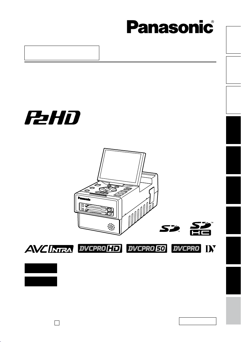
AG-HPG20P
AG-HPG20E
AG-HPG20
■
This product is eligible for the P2HD
5 Year Warranty Repair Program. For
details, see page 6.
IntroductionFor your
Operating Instructions
Memory Card Portable Recorder
Model No.
Model No.
parts
Name of the
Preparations
FRANÇAIS
ESPAÑOL
Before operating this product, please read the instructions carefully and save
this manual for future use.
F0109T0 -M
Printed in Japan
Pour des explications en français, veuillez vous reporter au CD-ROM fourni.
Para la explicación en español, consulte el CD-ROM uministrado.
D
ENGLISH
VQT1X51
Displays Editing Saving data Recording Playback
Menu
reference
Read this first!
CAUTION
RISK OF ELECTRIC SHOCK
DO NOT OPEN
CAUTION: TO REDUCE THE RISK OF ELECTRIC
SHOCK, DO NOT REMOVE COVER (OR BACK).
NO USER-SERVICEABLE PARTS INSIDE.
REFER TO SERVICING TO QUALIFIED SERVICE
WARNING:
TO REDUCE THE RISK OF FIRE OR
•
SHOCK HAZARD, DO NOT EXPOSE THIS
EQUIPMENT TO RAIN OR MOISTURE.
TO REDUCE THE RISK OF FIRE
•
OR SHOCK HAZARD, KEEP THIS
EQUIPMENT AWAY FROM ALL LIQUIDS.
USE AND STORE ONLY IN LOCATIONS
WHICH ARE NOT EXPOSED TO THE
RISK OF DRIPPING OR SPLASHING
LIQUIDS, AND DO NOT PLACE ANY
LIQUID CONTAINERS ON TOP OF THE
EQUIPMENT.
PERSONNEL.
The lightning flash with arrowhead symbol,
within an equilateral triangle, is intended to
alert the user to the presence of uninsulated
“dangerous voltage” within the product’s
enclosure that may be of sufficient magnitude
to constitute a risk of electric shock to
persons.
The exclamation point within an equilateral
triangle is intended to alert the user to
the presence of important operating and
maintenance (servicing) instructions in the
literature accompanying the appliance.
indicates safety information.
CAUTION:
THE MAINS PLUG OF THE POWER
SUPPLY CORD SHALL REMAIN READILY
OPERABLE.
THE AC RECEPTACLE (MAINS SOCKET
OUTLET) SHALL BE INSTALLED NEAR
THE EQUIPMENT AND SHALL BE EASILY
ACCESSIBLE.
TO COMPLETELY DISCONNECT THIS
EQUIPMENT FROM THE AC MAINS,
DISCONNECT THE POWER CORD PLUG
FROM THE AC RECEPTACLE.
CAUTION:
Danger of explosion or fire if battery is
mistreated.
For Battery Pack
Replace only with same or specified type.
•
Do not disassemble or dispose of in fire.
•
Do not store in temperatures over 60°C
•
(140°F).
Use specified charger.
•
Do not leave the battery in an automobile
•
exposed to direct sunlight for a long period
of time with doors and windows closed.
Memory Card Portable Recorder
The rating plate is on the underside of the unit.
AC Adapter
The rating plate is on the underside of the AC
Adapter.
Disconnect the AC mains plug from the AC
mains socket when not in use.
WARNING:
Always keep memory cards out of the reach of
babies and small children.
CAUTION:
TO REDUCE THE RISK OF FIRE OR SHOCK
HAZARD AND ANNOYING INTERFERENCE,
USE THE RECOMMENDED ACCESSORIES
ONLY.
CAUTION:
Excessive sound pressure from earphones
and headphones can cause hearing loss.
2
CAUTION:
In order to maintain adequate ventilation, do
not install or place this unit in a bookcase,
built-in cabinet or any other confined space.
To prevent risk of electric shock or fire hazard
due to overheating, ensure that curtains
and any other materials do not obstruct the
ventilation.
indicates safety information.
FCC NOTICE (USA)
Declaration of Conformity
Model Number: AG-HPG20P
Trade Name: Panasonic
Responsible Party: Panasonic Corporation of North America One Panasonic Way, Secaucus, NJ
Support contact: Panasonic Broadcast & Television Systems Company 1-800-524-1448
This device complies with Part 15 of FCC Rules.
Operation is subject to the following two conditions:
(1) This device may not cause harmful interference, and (2) this device must accept any
interference received, including interference that may cause undesired operation.
To assure continued compliance, follow the attached installation instructions and do not make any
unauthorized modifications.
07094
CAUTION:
This equipment has been tested and found to comply with the limits for a Class B digital device,
pursuant to Part 15 of the FCC Rules. These limits are designed to provide reasonable protection
against harmful interference in a residential installation. This equipment generates, uses and can
radiate radio frequency energy and, if not installed and used in accordance with the instructions,
may cause harmful interference to radio communications. However, there is no guarantee
that interference will not occur in a particular installation. If this equipment does cause harmful
interference to radio or television reception, which can be determined by turning the equipment off
and on, the user is encouraged to try to correct the interference by one of the following measures:
Reorient or relocate the receiving antenna.
•
Increase the separation between the equipment and receiver.
•
Connect the equipment into an outlet on a circuit different from that to which the receiver is
•
connected.
Consult the dealer or an experienced radio/TV technician for help.
•
The user may find the booklet “Something About Interference”
available from FCC local regional offices helpful.
FCC Warning:
To assure continued FCC emission limit compliance, follow the attached installation instructions and
the user must use only shielded interface cables when connecting to host computer or peripheral
devices. Also any unauthorized changes or modifications to this equipment could void the user's
authority to operate this device.
NOTIFICATION (Canada)
This class B digital apparatus complies with Canadian ICES-003.
Operating precaution
Operation near any appliance which generates strong magnetic fields may give rise to noise in the video
and audio signals. If this should be the case, deal with the situation by, for instance, moving the source
of the magnetic fields away from the unit before operation.
IMPORTANT
“Unauthorized recording of copyrighted television programs, video tapes and other materials may infringe the
right of copyright owners and be contrary to copyright laws.”
3
Read this first! (continued)
For U.K.
indicates safety information.
Caution for AC Mains Lead
FOR YOUR SAFETY PLEASE READ THE FOLLOWING TEXT CAREFULLY.
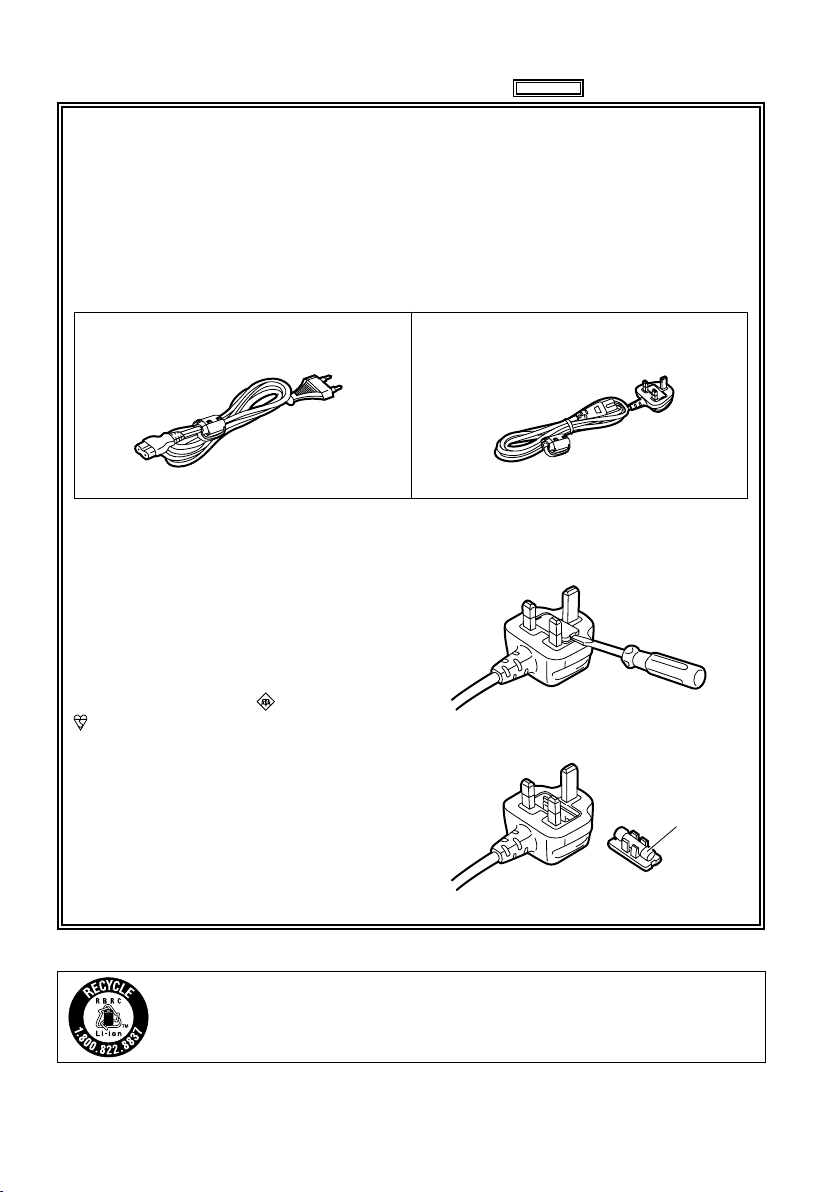
This product is equipped with 2 types of AC mains cable. One is for continental Europe, etc.
and the other one is only for U.K.
Appropriate mains cable must be used in each local area, since the other type of mains cable is
not suitable.
FOR CONTINENTAL EUROPE, ETC.
Not to be used in the U.K.
FOR U.K. ONLY
This appliance is supplied with a moulded
three pin mains plug for your safety and
convenience.
A 5 amp fuse is fitted in this plug.
Should the fuse need to be replaced please
ensure that the replacement fuse has a rating
of 5 amps and that it is approved by ASTA or
BSI to BS1362.
Check for the ASTA mark or the BSI mark
on the body of the fuse.
If the plug contains a removable fuse cover
you must ensure that it is refitted when the
fuse is replaced.
If you lose the fuse cover the plug must
not be used until a replacement cover is
obtained.
A replacement fuse cover can be purchased
from your local Panasonic Dealer.
FOR U.K. ONLY
How to replace the fuse
1. Open the fuse compartment with a
screwdriver.
2. Replace the fuse
Fuse
For USA and Canada
4
A lithium ion/polymer battery that is recyclable powers the product you have purchased.
Please call 1-800-8-BATTERY for information on how to recycle this battery.

IMPORTANT SAFETY INSTRUCTIONS
1) Read these instructions.
2) Keep these instructions.
3) Heed all warnings.
4) Follow all instructions.
5) Do not use this apparatus near water.
6) Clean only with dry cloth.
7) Do not block any ventilation openings. Install in accordance with the manufacturer’s instructions.
8) Do not install near any heat sources such as radiators, heat registers, stoves, or other apparatus
(including amplifiers) that produce heat.
9) Do not defeat the safety purpose of the polarized or grounding-type plug. A polarized plug has two
blades with one wider than the other. A grounding-type plug has two blades and a third grounding
prong. The wide blade or the third prong are provided for your safety. If the provided plug does not fit
into your outlet, consult an electrician for replacement of the obsolete outlet.
10) Protect the power cord from being walked on or pinched particularly at plugs, convenience
receptacles, and the point where they exit from the apparatus.
11) Only use attachments/accessories specified by the manufacturer.
12) Use only with the cart, stand, tripod, bracket, or table specified by the manufacturer, or
sold with the apparatus. When a cart is used, use caution when moving the cart/
apparatus combination to avoid injury from tip-over.
13) Unplug this apparatus during lightning storms or when unused for long periods of time.
14) Refer all servicing to qualified service personnel. Servicing is required when the
apparatus has been damaged in any way, such as power-supply cord or plug is
damaged, liquid has been spilled or objects have fallen into the apparatus, the apparatus has been
exposed to rain or moisture, does not operate normally, or has been dropped.
IMPORTANT SAFETY INSTRUCTIONS
Recommendation for Use of Genuine Panasonic Battery (Rechargeable Battery)
Thank you for using a Panasonic product.
It has been found that counterfeit battery packs which look very similar to the genuine product are
made available to purchase in some markets. Some of these battery packs are not adequately
protected with internal protection to meet the requirements of appropriate safety standards. There is
a possibility that these battery packs may lead to fire or explosion. Please be advised that we are not
liable for any accident or failure occurring as a result of use of a counterfeit battery pack. To ensure that
safe products are used we would recommend that a genuine Panasonic battery pack is used.
Be aware that many batteries sold at extremely cheap prices or in situations where it is difficult to
•
verify the actual products before purchase have proven to be counterfeit.
5
To remove the battery
PUSH
OUTPUT INPUT
CH 1
CH 2
AUDIO
VIDEO
HD/SD-SDI HD/SD-SDI
DVCPRO/DV
*1: Please note that this extended warranty is not available in some countries/regions.
*2: Not all models eligible for extended warranty coverage.
*3: The basic warranty period may vary depending on the country/region.
*4: Not all repair work is covered by this extended warranty.
*5: The maximum warranty period may be adjusted depending on the number of hours
the device has been used.
1st year
2nd year 3rd year 4th year
5th year
*
5
P2HD
device
*
2
Basic
warranty
*
3
Extended warranty repair
*
4
Purchase
P2 product
Register online
within 1 month
“Registration Notice”
e-mail sent
Details about user registration and the extended warranty:
http://panasonic.biz/sav/pass_e/
Free 5 years of Warranty Repairs
Customers who register as users on the website will receive
an extended warranty repair valid for up to five years.
P2HD 5 Year Warranty Repair Program*
1
Thank you for purchasing this Panasonic P2HD device.
Register as a user for this device to receive a special service warranty up to five
years of free warranty repairs.
Make sure to save the “Registration Notice”
e-mail during the warranty period.
Please note, this is a site that is not maintained by Panasonic Canada Inc. The Panasonic Canada Inc. privacy
policy does not apply and is not applicable in relation to any information submitted. This link is provided to
you for convenience.
Main Power Battery
Remove the battery while pressing the battery
eject button.
Battery
eject
button
Back-up Battery (Lithium Battery)
For the removal of the battery for disposal at the
end of its service life, please consult your dealer.
6

EMC NOTICE FOR THE PURCHASER/USER OF THE APPARATUS
1. Applicable standards and operating environment for AG-HPG20E
The apparatus is compliant with:
• standards EN55103-1 and EN55103-2 1996.and
• electromagnetic environments E1, E2, E3, E4 and E5.
2. Pre-requisite conditions to achieving compliance with the above standards
<1> Peripheral equipment to be connected to the apparatus and special connecting cables
• The purchaser/user is urged to use only equipment which has been recommended by us
as peripheral equipment to be connected to the apparatus.
• The purchaser/user is urged to use only the connecting cables described below.
<2>
For the connecting cables, use shielded cables which suit the intended purpose of the apparatus.
• Video signal connecting cables
Use double shielded coaxial cables, which are designed for 75-ohm type high-frequency
applications, for SDI (Serial Digital Interface).
Coaxial cables, which are designed for 75-ohm type high-frequency applications, are
recommended for analog video signals.
• Audio signal connecting cables
If your apparatus supports AES/EBU serial digital audio signals, use cables designed for
AES/EBU.
Use shielded cables, which provide quality performance for high-frequency transmission
applications, for analog audio signals.
• Other connecting cables (IEEE1394, USB)
Use shielded cables, which provide quality performance for high-frequency applications, as
connecting cables.
• If your apparatus is supplied with ferrite core(s), they must be attached on cable(s)
following instructions in this manual.
3. Performance level
The performance level of the apparatus is equivalent to or better than the performance level
required by these standards.
However, the apparatus may be adversely affected by interference if it is being used in an EMC
environment, such as an area where strong electromagnetic fields are generated (by the presence
of signal transmission towers, cellular phones, etc.). In order to minimize the adverse effects of the
interference on the apparatus in cases like this, it is recommended that the following steps be
taken with the apparatus being affected and with its operating environment:
1. Place the apparatus at a distance from the source of the interference.
2. Change the direction of the apparatus.
3. Change the connection method used for the apparatus.
4. Connect the apparatus to another power outlet where the power is not shared by any
other appliances.
7

Operating precautions
When using the unit in rainy or snowy weather,
at the beach or other locations, take care to
protect it from precipitation and sea water.
Otherwise, trouble may occur in the unit and
•
its cards. (It may not be possible to restore the
original functions)
Keep the unit away from appliances (such
as TV sets and TV game machines) which
generate magnetic fields.
When the unit is used on top of or near a TV set,
•
the images and sound may be distorted by the
electromagnetic waves emanating from the TV
set.
Strong magnetic fields generated by speakers
•
or large motors may damage the recordings or
distort the images.
The electromagnetic waves emanating from
•
microprocessors may adversely affect the unit
and distort the images and sound.
If the unit is adversely affected by an appliance
•
that generates magnetic fields and fails to
operate properly as a result, turn off its power,
and either remove its battery or unplug the AC
adapter from the power outlet. Then install the
battery again or re-connect the AC adapter. After
doing this, turn the unit’s power back on.
Do not use the unit near a radio transmitter or
high-voltage appliance.
Doing so may adversely affect the recorded
•
images and sound.
AC adapter and battery
When the battery temperature is extremely high
•
or extremely low or when the battery has not
been used for a prolonged period and been left
discharged, the [CHARGE] lamp will blink several
times, and charging will start automatically.
If the [CHARGE] lamp continues blinking even
•
when the battery temperature is normal, this may
be a sign of trouble in the battery or AC adapter.
Consult with your dealer.
When the battery is warm, it will take longer than
•
usual to recharge it.
When the AC adapter is used near a radio, the
•
sound from the radio may be distorted. Use the
AC adapter and radio at a distance of at least 1
meter from each other.
Noise is output while the AC adapter is being
•
used, but this is not a sign of trouble.
When carrying the unit around, take care not
to drop it.
Strong impacts may damage the unit’s body,
•
preventing it from operating properly.
Do not expose the unit to insecticides or
volatile sprays or liquids.
These substances may deform the unit’s body or
•
cause its paint to peel off.
Do not bring the unit into contact with products
•
made of rubber or vinyl for prolonged periods of
time.
When using the unit at the beach or similar
locations, take care to protect it from sand and
dust.
Sand and dust may damage the unit and its
•
cards. (Take particular care when inserting or
ejecting the cards)
8

Characteristics of the battery
A rechargeable lithium-ion battery is used in this
unit. Electrical energy is generated by the chemical
reactions taking place inside it. These reactions
are susceptible to the effects of the ambient
temperature and humidity, and the higher or the
lower the temperature, the quicker the battery
charge will be used up. When the battery is used
where the temperature is extremely low, it may last
only 5 minutes or so even if the battery has been
fully charged.
When the battery reaches an extremely high
temperature, its protection function is activated,
making it impossible for the battery to be used for
a while.
After using the unit, always remember to
remove the battery.
Be sure to remove the battery from the unit. (If it
is left in place, a very faint current will continue to
flow even when the unit’s power has been turned
off) If the battery is left in place for a prolonged
period, it may discharge excessively so that it
cannot be used again even when it is charged at a
later time.
Protect the battery terminals.
Keep the battery terminals free from dust and
foreign matter.
If the battery has been inadvertently dropped,
check whether its body and terminal area have
been deformed.
Installing a deformed battery in the unit or in the
AC adapter may damage the unit or AC adapter.
Precautions when P2 cards and SD cards are to
be destroyed or given to other parties
The formatting and deletion functions provided by
the unit and personal computers serve merely to
change the file management information: they will
not completely erase all the data on the card.
When a card is to be destroyed or given to
another party, it is recommended that you destroy
the actual card physically or use a data deletion
software program for use with personal computers
available on the market to completely erase all the
data on the card.
You, the user, are responsible for managing the
data on your cards.
Liquid crystal display
When the same image or characters are left
•
displayed on the LCD monitor for a prolonged
period, they may become burned into the screen.
However, the original condition of the screen will
be restored after the power has been kept off for
several hours.
The liquid crystal part of the monitor has been
•
fabricated using high-precision technology. The
number of its effective pixels is more than 99.99
%, but this still leaves less than 0.01 % of its
pixels which may be missing or permanently
lighted. This is not a sign of trouble and will have
absolutely no effect on the images which have
been recorded.
The surface of the liquid crystal display may be
•
marked or scratched if it is wiped or rubbed firmly
with a rough cloth.
The response speed and brightness of the liquid
•
crystal change depending on the temperature at
which the display is used.
Condensation may form on the liquid crystal part
•
of the monitor if the unit is placed in a location
where there is a significant difference in the
temperature levels. If this happens, wipe off the
condensation with a soft dry cloth.
If the unit becomes very cold, the LCD monitor
•
screen will be darker than usual immediately
after the power has been turned on. When the
temperature inside the unit rises, the normal
brightness will be restored.
Connector protection
Attach the connector covers when the connectors
are not in use.
9

Contents
Read this first! ................................................2
IMPORTANT SAFETY INSTRUCTIONS .........5
Recommendation for Use of Genuine
Panasonic Battery
(Rechargeable Battery) .......................... 5
Operating precautions ...................................8
How to use the unit ......................................12
Introduction
About this manual ........................................15
Before use ..................................................... 15
Accessories ..................................................17
Name of the parts
Name of the parts .........................................18
Operation area ................................................ 18
Mechanism area and input/output connector
area ............................................................. 19
Preparations
Charging the battery ....................................20
Charging .......................................................... 20
Installing and removing the power
supply ....................................................21
Installing and removing the battery ................. 21
Connecting and disconnecting
the power cable ...........................................21
Basic operations........................................... 22
Turning the power on and off ........................... 22
Using the LCD monitor .................................... 22
Menu operations .............................................. 23
Operation modes ............................................. 24
LCD monitor settings ....................................... 26
Setting date and time ...................................... 27
P2 cards......................................................... 28
Inserting P2 cards ........................................... 28
P2 card access LED and P2 card status ......... 28
Formatting P2 cards ........................................ 29
P2 card protection ...........................................29
Ejecting P2 cards ............................................ 30
P2 card recording durations ............................31
Dividing clips over 4 GB in size ....................... 31
LOOP REC recording ...................................... 32
Other .............................................................. 32
USER button ................................................... 32
Charging the internal battery ........................... 32
Using SD/SDHC memory cards ................... 33
Inserting and removing the SD card ................ 33
Formatting SD cards ....................................... 33
Precaution for using SD cards ......................... 33
Saving USER files on SD cards................... 34
10
Playback
Thumbnail display ........................................ 35
Playback formats ............................................. 35
Names and functions of thumbnail display
screen parts ................................................. 35
Changing the displays on the thumbnail
display screen ............................................. 38
Setting the items to be displayed .................... 39
Clip management.......................................... 40
Selecting clips ................................................. 40
Deleting clips ................................................... 40
Repairing and connecting clips ....................... 41
Copying clips ................................................... 42
Displaying the clip information ......................... 43
Editing the clip information ..............................45
Adding meta-data to clips ................................ 46
Adding shot marks to clips .............................. 54
Displaying the P2 card status .......................... 54
Displaying SD card information ....................... 56
Clip playback ................................................57
Playing back clips ............................................ 57
Single clip playback ......................................... 58
Variable-speed playback ................................. 59
Clip and text memo forward/reverse ............... 59
Rapid forward/rapid reverse playback ............. 59
Frame feed playback ....................................... 59
Repeat playback .............................................. 59
Adding text memos .......................................... 60
Playback from text memo position .................. 60
Deleting text memos ........................................ 61
Dividing and copying clips using text memos
Replacing thumbnail images ...........................61
... 61
Outputting images to an external monitor
for playback .......................................... 62
Setting the outputs .......................................... 62
Adjusting the output volume level during
recording and playback ............................... 62
Adjusting the output volume level during
variable-speed playback .............................. 62
Recording
Recording data on P2 cards ........................ 63
Recording ........................................................ 63
2-slot continuous recording ............................64
Waveform monitor (WFM) displays ................. 64
Time code displays .......................................... 65
Setting the recording time code ....................... 65
Set the user’s bit .............................................. 66

Saving data
Copying data from P2 cards to the
hard drive .............................................. 67
Switching to the USB HOST mode .................. 68
Usable hard drives .......................................... 68
Types of hard drives and usable functions ...... 69
Formatting the hard drive ................................70
Exporting data to a hard drive in 1-card
increments ................................................... 71
Exporting one clip at a time to a hard drive ..... 72
Hard drive data display .................................... 74
Deleting the partition ....................................... 75
Thumbnail displays of clips on the hard drive
Displaying the clip information on the
hard drive ....................................................76
... 76
Connecting the hard drive for use .............. 77
Importing data from a hard drive to P2 cards
Easy playback of clips on the hard drive
(For viewing materials) ................................78
Deleting clips on the hard drive ....................... 78
... 77
Editing
Editing by means of external devices ........79
Editing data content on the P2 card
(USB DEVICE mode) .................................. 79
Editing in the USB DEVICE mode ................... 79
Displays
Screen displays ............................................80
Normal displays ............................................... 80
Major warning displays .................................... 82
Selecting what is to be displayed
on the screen ............................................... 85
Recording/output supporting format ..........86
Menu
Basic operations on the setting menus .....88
Initializing the setting menu ............................. 88
Setting menu configuration ......................... 89
List of setting menus ...................................90
RECORDING SETUP screen .......................... 90
TIMECODE SETUP screen ............................. 93
SW MODE screen ........................................... 97
PLAYBACK FUNCTIONS screen .................... 98
AV OUT SETUP screen ................................... 99
DISPLAY SETUP screen ............................... 103
CARD FUNCTIONS screen .......................... 105
OTHER FUNCTIONS screen ........................ 106
DIAGNOSTIC screen ....................................107
OPTION MENU screen .................................108
For your reference
Warning system table ................................109
Troubleshooting (Q&A) .............................. 110
Software information for this product ...... 112
Updating the drivers installed
in the unit ............................................. 113
Maintenance ................................................ 113
Condensation .............................................. 113
Storage precautions ................................... 114
Handling the data recorded on
P2 cards ............................................... 115
Use of SD/SDHC memory cards ................ 116
Specifications ............................................. 117
11
How to use the unit
AG-HPG20
AG-HPG20
AG-HPG20
Housed in a compact cabinet which can be battery-powered, this Memory Card Portable Recorder is
a compact recording/playback unit coming with two P2 card slots, a 3.5-inch LCD monitor, USB 2.0,
IEEE1394, composite signal, SDI and many other input/output signal connectors. It can be easily operated
to play back the data content which has been shot by a P2 camera recorder. It is also capable of backup
recording and file management, and it supports outdoor field recording.
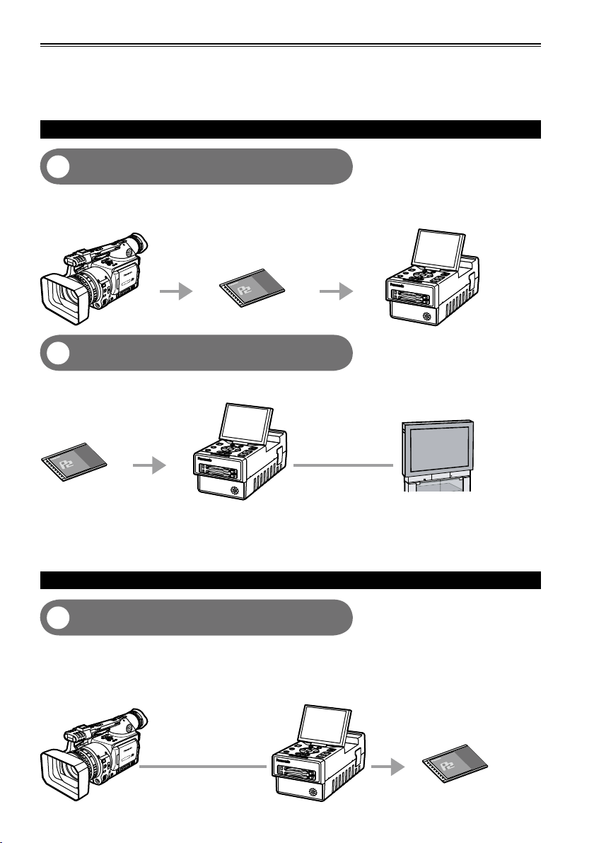
Playing back data content on the P2 card
Playing back the data on the unit’s LCD
1
monitor (Page 57)
Data content (both pictures and sound) which has been shot on P2 cards using a P2 camera recorder can
be played back on the spot.
P2 camera recorder
P2 card
Outputting the data to the external monitor
2
for playback (Page 62)
The data content (both pictures and sound) on P2 cards can be output to the external monitor, and played back.
AG-HPG20 (this unit)
P2 card
HD/SD-SDI output
AG-HPG20 (this unit)
External monitor
Video output/Audio
output
Use VIDEO/SDI/1394 output for monitoring purpose in other modes than playback mode. It is not
•
suitable for recording purpose because Pictures/Sound/Time cord (TC/UB) may become incorrect.
If the content on the P2 card has been recorded in DVCPRO HD, DVCPRO50, DVCPRO25 or DV
•
format, signals are also output from DVCPRO/DV input/output connector (IEEE1394).
(AVC-Intra100 and AVC-Intra50 do not support 1394 output)
Recording data on P2 cards
1394 connection (Page 63)
3
You can record data on P2 cards by connecting the unit to the external devices equipped with 1394
(DVCPRO/DV stream) output, such as a P2 camera recorder. The unit’s recording start and stop
operations can be performed from some camera recorders.
Recording in AVC-Intra100 and AVC-Intra50 modes is not possible with 1394 input.•
P2 camera recorder
1394 cable
AG-HPG20 (this unit)
P2 card
12
AG-HPG20
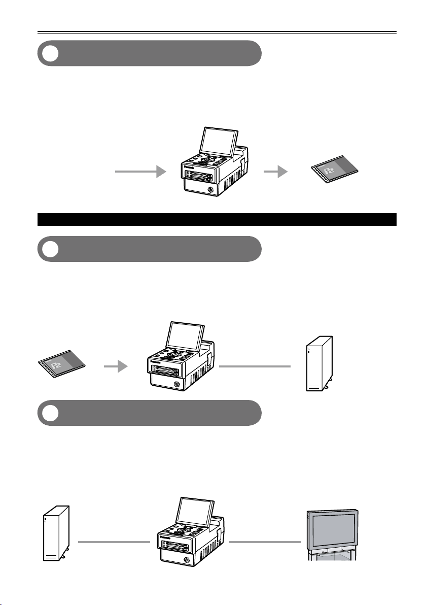
HD/SD-SDI connection (Page 63)
AG-HPG20
AG-HPG20
4
You can record data on P2 cards by connecting the unit to the external devices equipped with HD/SD-SDI
output. The unit’s recording start and stop operations can be performed from some camera recorders.
(When SDI input is selected)
(For supporting devices, refer to page 91)
AG-HPG20 (this unit)
P2 card
HD/SD-SDI signal
Using an external hard drive (HDD)
Saving data onto an external hard drive
5
(Page 67)
The data content on P2 cards can be saved onto an external HDD.
Also, the P2 content saved on an external HDD can be reloaded onto a P2 card.
(Only in the USB HOST mode)
1394 connection (File transfer) is not supported.•
AG-HPG20 (this unit)
Hard drive
P2 card
USB 2.0 cable
Checking the content saved onto an
6
external hard drive (Page 78)
The P2 content saved on an external HDD can be played back and checked. (Pulldown playback
(Playback with some images skipped))
(Only in the USB HOST mode)
1394 connection (File transfer) is not supported.
•
Both audio and images will not be output to the DVCPRO/DV input/output connector (IEEE1394).
•
Hard drive
USB 2.0 cable
AG-HPG20 (this unit)
External monitor
HD/SD-SDI output
Video output/Audio
output
13
How to use the unit (continued)
AG-HPG20
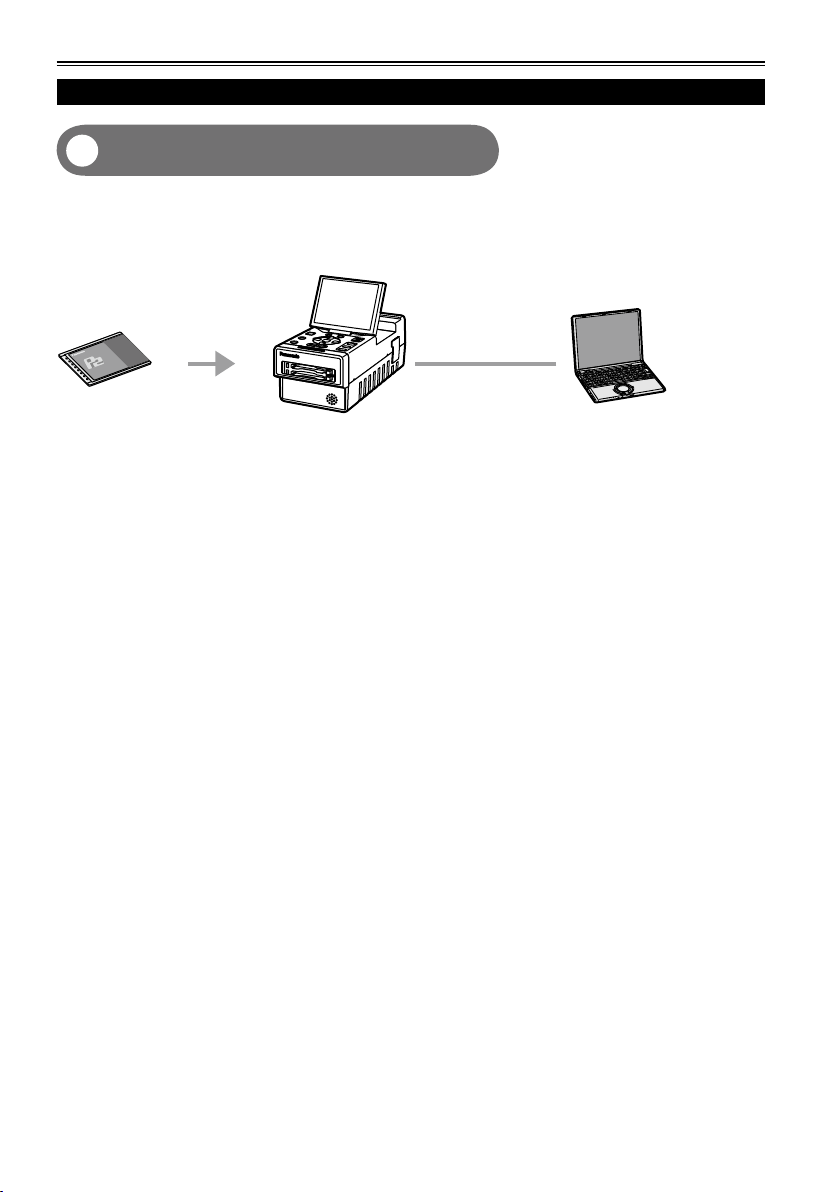
Using a PC
Editing by connecting the unit to a PC
7
(Page 79)
The unit can be USB-connected to a PC, and the PC can then be used to edit (i.e. exchanging data, etc.)
the data content on P2 cards. (USB DEVICE mode)
1394 connection (File transfer) is not supported.•
AG-HPG20 (this unit)
PC
P2 card
USB 2.0 cable
14
IEEE1394
connector
IEEE1394
cable edge
IEEE1394
connector
(Wrong)
(Correct)
IEEE1394
cable edge
About this manual
Note concerning illustrations in these instructions
• Illustrations (portable recorder, menu screens, etc.) in these operating instructions differ slightly from the
actual portable recorder.
References
• References are shown as (Page 15).
Each explanation, company names and product names described in these operating instructions are
trademarks or registered trademarks of each company.
Before use
Be absolutely sure to check the date, time and time zone, and set them if necessary.
The calendar and time zone affect the management and playback sequence of the data content which
•
has been recorded. Before recording, set and check year/month/day, time and time zone. (Page 27)
No compensation can be made for video recordings.
The manufacturer will not provide any compensation in the event that images fail to be recorded due to
•
trouble while the unit and P2 card are being used.
Concerning copyrights
You may use the images and sound which you have recorded for your own personal enjoyment only;
•
under copyright laws, you may not use them for any other purpose without the permission of the
copyright holders.
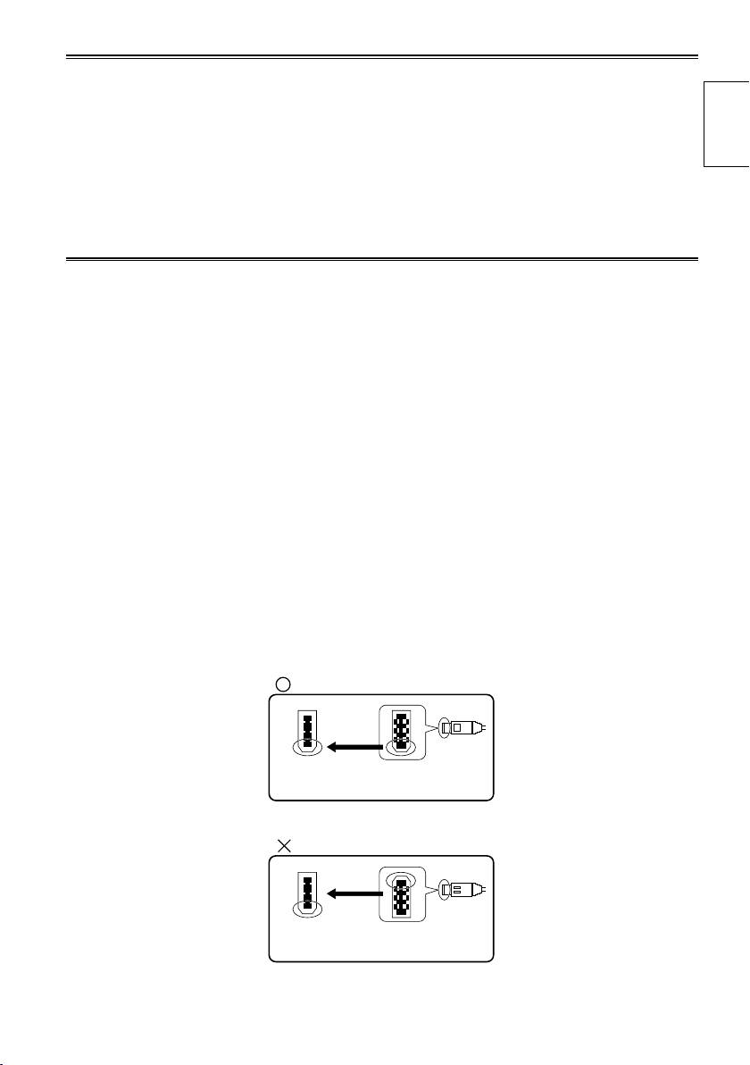
IEEE1394 cable connection
Be sure to observe the following when connecting the IEEE1394 cable (optional). (Improper connection
may cause malfunction in this unit and external devices)
Before connecting or disconnecting the IEEE1394 cable, you must turn off the power of all devices
•
connected to the unit.
Devices equipped with earth terminals must be used in the grounded condition (or in the connected
condition to the commonly-used GND).
When connecting the unit to a component which uses a 4-pin type of connector, be sure to connect this
•
unit’s connector (6-pin type) first.
IEEE1394 cable connector has a direction.
•
When connecting the unit to a component which uses a 6-pin type of IEEE1394 connector, be sure to
•
check the shape before connection as below
Introduction
During recording or playback in AVC-Intra100 and AVC-Intra50 modes, input/output from the DVCPRO/
•
DV input/output connector (IEEE1394) is not possible.
15
Before use (continued)
Media which can be used with this unit
You may use the following media. For further details, refer to the pages on the media concerned.
P2 cards (Page 28)
•
SD/SDHC memory cards (Page 33)
•
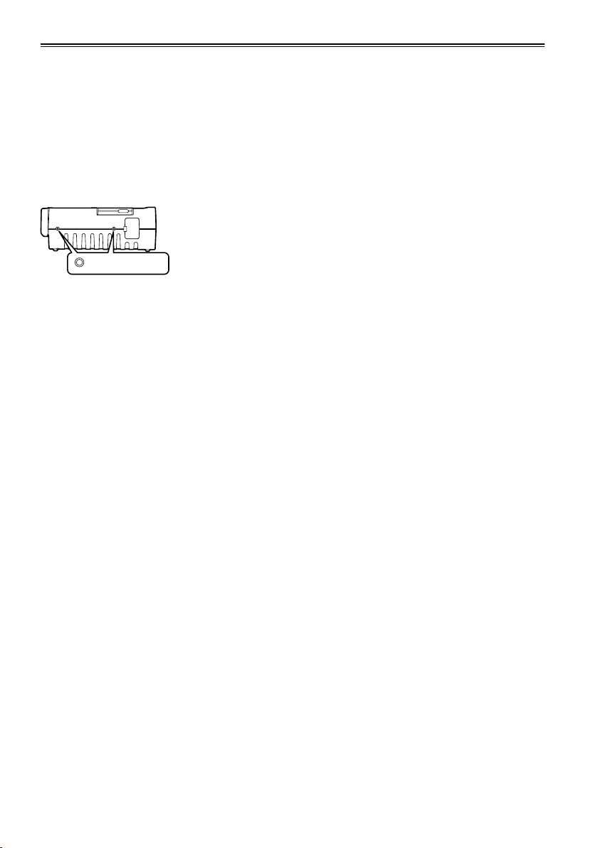
Screw holes
M5 (5 mm diameter) screws with a length of 10 mm can be used for the four screw holes on the side
panels of the unit.
When using the screws, do not tighten them too much. The unit may be damaged if screws other than 10
mm long M5 (5 mm diameter) screws are used.
Screw holes
Refer to page 8 for other operating precautions.
The other side panel also has two screw holes.
16
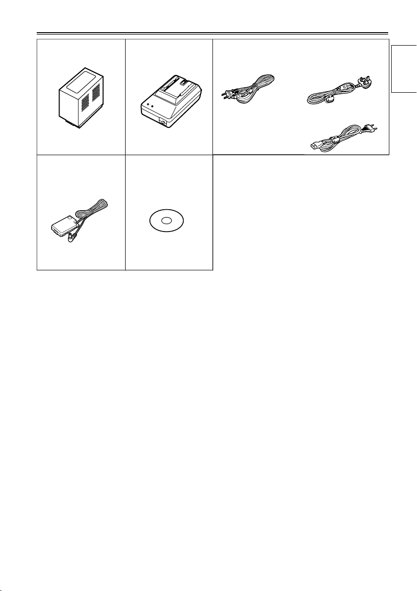
Accessories
*
Battery
DC cord
* For the model number of the battery, refer to the [ACCESSORIES] item. (Page 118)
AC adapter
CD-ROM
AC power supply cords
AG-HPG20P AG-HPG20E
( For the U.K.)
Introduction
( For areas other than
the U.K.)
17
Name of the parts
EXIT/2
ALT/3
3
5
7
8
9
10
11
13
12
4
6
2
1
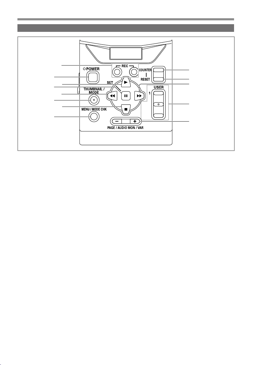
Operation area
1 REC button (Page 63)
2 POWER button (Pages 22, 110)
3 PLAY button (Pages 23, 58)
4 STILL/SET button (Pages 23, 58)
5 REW button (Pages 23, 58)
6 THUMBNAIL/MODE button
(Page 24)
7 STOP button (Pages 23, 58)
8 MENU/MODE CHK button
(Pages 23, 32)
9 COUNTER button (Page 65)
10 RESET button
(Pages 26, 34, 65, 66)
11 FF button (Pages 23, 58)
12 USER/EXIT/ALT button (Page 32)
13 PAGE/AUDIO MON/VAR button
(Pages 40, 59, 62)
• The button names are described such as
[THUMBNAIL/MODE] in this manual from now.
18
Mechanism area and input/output connector area
EXIT/2
ALT/3
1
USER
SET
THUMBNAIL
/MODE
MENU/MODE CHK
REC
PAGE / AUDIO MON / VAR
POWER
COUNTER
RESET
AG-HPG20
PUSH
HOST
DEVICE
OUTPUT INPUT
CH 1
CH 2
AUDIO
VIDEO
DVCPRO/DV
HD/SD-SDI HD/SD-SDI
1
6
7
4
3
2
5
8
20
13
921
18
19
11
10
14 15 16 17
12
parts
Name of the
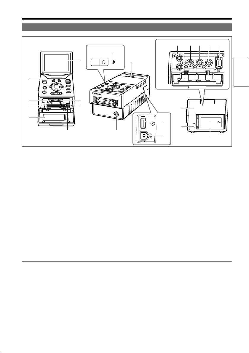
1 LCD monitor (Pages 22, 26)
2 Power display LED (Pages 22, 109)
3 SD card access LED (Page 33)
4 P2 card access LEDs (Page 28)
5 Card slot cover (Pages 28, 30)
6 SD card slot (Page 33)
7 P2 card slots (Page 28)
8 LCD monitor open button (Page 22)
9 Speaker (Pages 62, 82)
10 Connector area cover
11 Battery eject button (Page 21)
12 Battery (Page 20)
Use a cable equivalent level of 5C-FB with a double-layer shield to connect to HD/SD-SDI IN or HD/SD-
•
SDI OUT connector.
Use a cable with a double-layer shield to connect to DVCPRO/DV input/output connector (IEEE1394).
•
13 AUDIO OUT CH1/CH2 connectors
(Page 62)
14 VIDEO OUT connector (Page 62)
15 HD/SD-SDI OUT connector (Page 62)
16 HD/SD-SDI IN connector (Page 63)
17 DVCPRO/DV input/output connector
(IEEE1394) (Page 63)
18 USB HOST connector (USB2.0 Type A)
(Page 67)
19 USB DEVICE connector (USB2.0 Type B)
(Page 79)
20 Headphone jack (Pages 62, 82)
21 P2 card eject button (Page 30)
19
Charging the battery
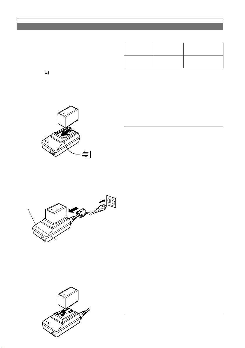
Charging
The battery has not been charged at the time of
purchase.
Before using the battery, give it a full charge using
the AC adapter. It is recommended that you have a
spare battery available in case you need it.
1 Place the battery horizontally while aligning
it with the mark on the AC adapter, and
slide it into position.
If the DC cord is connected to the AC adapter,
•
disconnect it before proceeding any further.
The battery cannot be charged if this cable is
left connected.
2 Connect the AC cable to the power outlet.
The POWER and CHARGE lamps on the AC
•
adapter light, and charging starts.
If the CHARGE lamp fails to light when the
•
battery has been installed, remove the battery
and then re-install it.
POWER
CHARGE
When the battery has been charged, the
•
CHARGE lamp on the AC adapter goes off.
Depending on the country and region, the
•
actual configuration of the power cord, plug,
and power outlet may differ from those shown
in these operating instructions.
3
Slide the battery out of position, and remove it.
Charging time and play time of supplied battery
Capacity Charging
time
5400 mAh Approx. 330
minutes
The times given in the above table are
•
approximate figures based on playback in the
AVC-Intra100 mode.
The times given in the above table are obtained
•
at an ambient operating temperature of 20 °C (68
°F) and an ambient relative humidity of 60 %. It
may take longer to charge the battery at other
temperature and humidity levels.
While the battery is being used or charged, it will
•
become hot.
If the playback and stop operations are repeated
•
more than necessary, the playback time will be
shorter than the time given in the above table.
When the battery is to be stored for a prolonged
period, it is recommended that you charge it once
a year, use the battery in the unit until its charge
is used up, and then return it to storage.
When the battery temperature becomes
•
extremely high or low or when a discharged
battery has been left unused for a prolonged
time, the CHARGE lamp will blink several times,
and charging will commence automatically.
When the CHARGE lamp continues to blink even
•
when the battery is at the right temperature,
it may indicate a failure in the battery or AC
adapter. Contact your dealer.
When the battery is warm, it will take longer than
•
usual to recharge it.
When the AC adapter is used near a radio, the
•
sound from the radio may be distorted. Use the
AC adapter and radio at a distance of at least 1
meter from each other.
Noise may be heard from the AC adapter while
•
the AC adapter is being used: this is normal and
not a sign of trouble.
The battery cannot be charged when power is
•
supplied to the unit from the AC adapter.
No guarantees are given for the operation of the
•
CGR-D16/CGR-D16s (1600 mAh) battery pack.
Continuous
playback time
Approx. 230
minutes
20
Installing and removing the power supply
PUSH
OUTPUT INPUT
CH 1
CH 2
AUDIO
VIDEO
HD/SD-SDI HD/SD-SDI
DVCPRO/DV
PUSH
OUTPUT INPUT
CH 1
CH 2
AUDIO
VIDEO
HD/SD-SDI HD/SD-SDI
DVCPRO/DV
PUSH
OUTPUT INPUT
CH 1
CH 2
AUDIO
VIDEO
HD/SD-SDI HD/SD-SDI
DVCPRO/DV
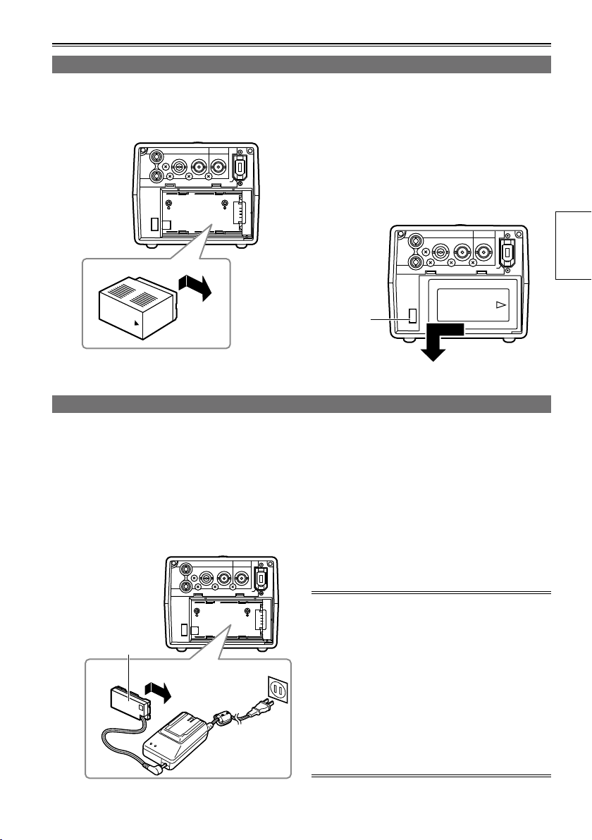
Installing and removing the battery
Insertion
1 Slide and insert the battery until it clicks
Removal
1 Press [POWER] for at least 2 seconds to
into place.
2 Remove the battery while pressing the
Connecting and disconnecting the power cable
Insertion
1 Connect the DC cord to the AC adapter.
Removal
1 Press [POWER] for at least 2 seconds to
2 Connect the AC power supply cord into the
power outlet.
2 Remove the DC cord’s battery connector
3 Slide and insert the DC cord plate until it
clicks into place.
3 Disconnect the AC power supply cord from
turn the power off, and check that the power
display LED has gone off. (Page 22)
battery eject button.
Support the battery with your hand to ensure
•
that it will not drop down.
Battery
eject
button
turn the power off, and check that the power
display LED has gone off. (Page 22)
while pressing the battery eject button.
the power outlet.
Preparations
DC cord’s
battery
connector
The battery cannot be charged when power is
•
supplied to the unit from the AC adapter.
The AC adapter is designed to work anywhere
•
in the world with supply voltages ranging from
100 V to 240 V and with power line frequencies
of 50 Hz and 60 Hz. However, in some countries
the shape of the power outlet receptacle differs.
In cases like this, obtain the plug that will fit the
receptacle. Obtain the conversion plugs after
consulting with your dealer.
When the unit is not being used, disconnect the
•
AC cable from the power outlet.
21
Basic operations
AG-HPG20
AG-HPG20
AG-HPG20
AG-HPG20
EXIT/2
ALT/3
1
USER
SET
THUMBNAIL
/MODE
MENU/MODE CHK
REC
PAGE / AUDIO MON / VAR
POWER
COUNTER
RESET
Turning the power on and off
Hold down [POWER] for at least 1 second.
The power display LED lights, and the power is turned on.
•
When [POWER] has been held down for more than 2 seconds while the power is on, the power display
•
LED will go off, and the power will be turned off.
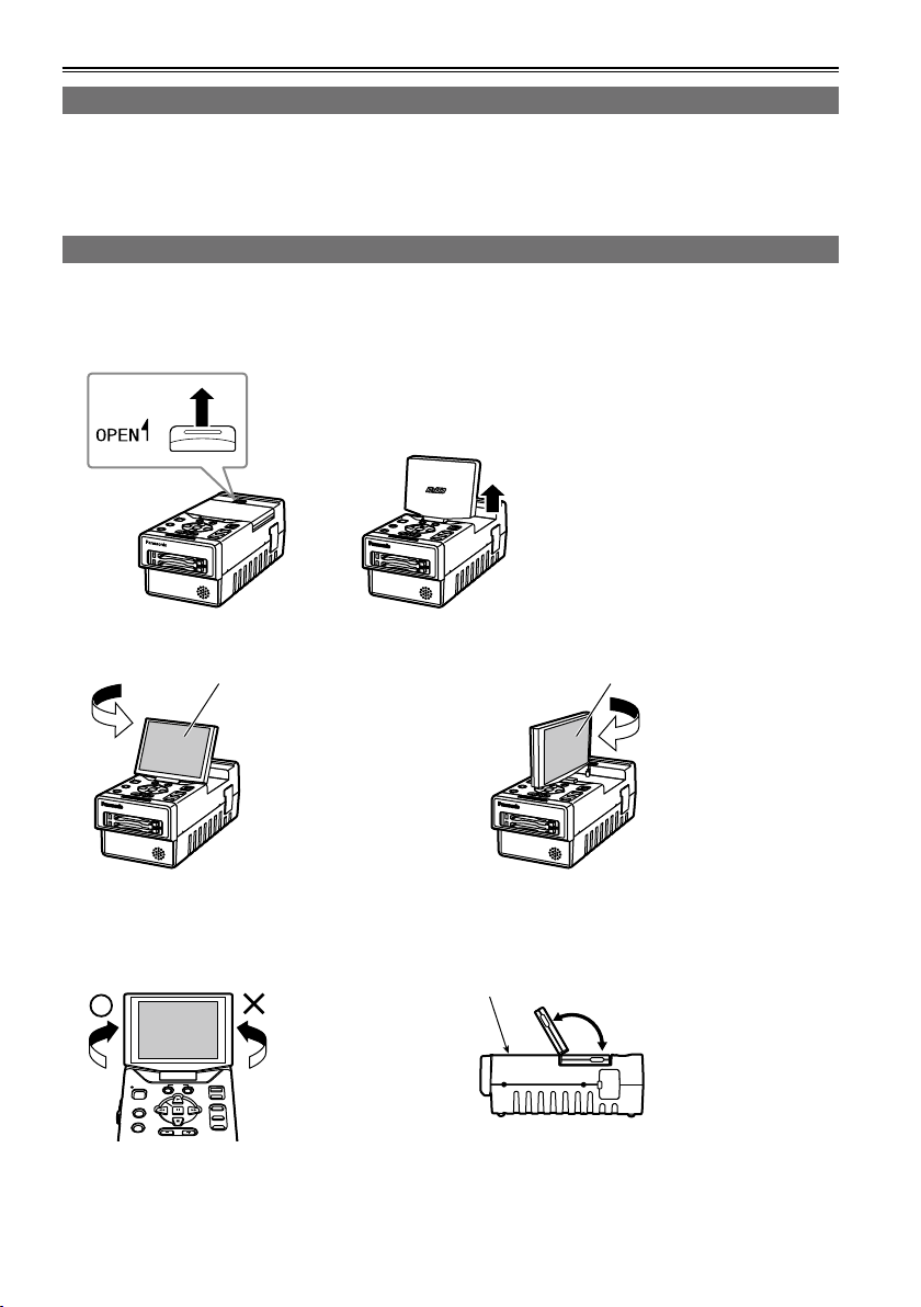
Using the LCD monitor
1 Hold down [POWER] for at least 1 second to turn the power on.
2 Raise the LCD monitor while pressing the LCD monitor open button in the direction shown by
the arrow.
3 Set the LCD screen to the angle where it is easiest to see its displays.
180º
Turn the LCD monitor
screen 180 degrees
counterclockwise so that
it is facing the front.
LCD monitor screen LCD monitor screen
The monitor cannot
•
be turned more than
180 degrees. Applying
excessive force beyond
this limit may cause
damage the unit.
Make sure that the LCD monitor is raised upright before turning it.
Once the LCD monitor
screen is positioned to
face the front, it cannot
be turned any further
in the counterclockwise
direction.
Applying excessive
•
force beyond this limit
may cause damage
the unit.
22
Function buttons
90º
In the clockwise
direction, the screen
can be turned up to 90
degrees.
The monitor cannot
•
be turned more than
90 degrees. Applying
excessive force beyond
this limit may cause
damage the unit.
120º
The LCD monitor screen
will not tilt more than
120 degrees toward the
function buttons.
Applying excessive
•
force beyond this limit
may cause damage
the unit.
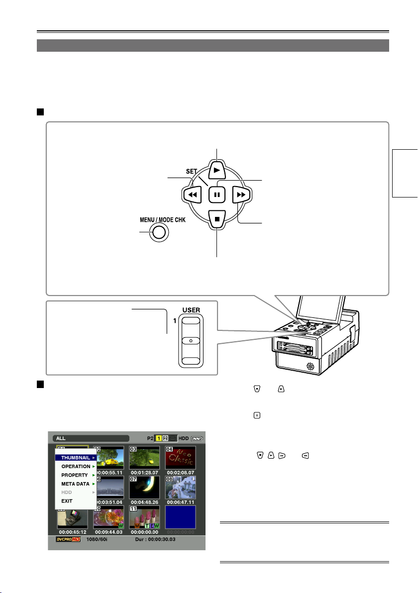
Menu operations
AG-HPG20
EXIT/2
ALT/3
This unit is provided with three kinds of screens: the thumbnail display screen, normal display screen
(SDI/1394 input recording standby mode, INT SG (Page 91), playback standby mode, etc.) and PC mode
screen (USB HOST mode, USB DEVICE mode). When [MENU/MODE CHK] is pressed on any of these
screens, the menu will be displayed. (No menus are displayed in the USB DEVICE mode)
Operations performed when the function buttons are pressed
This is used to move the menu highlighting to the item above;
depending on the menu item, it is used to change the value.
This is used to move the menu
highlighting to the item on the left;
depending on the menu item, it is
used to change the value.
This is used to display
the menus. When it is
pressed while a menu is
displayed, the menu is
exited.
When EXIT is assigned
to [EXIT/2], if you press
[EXIT/2] while a menu
is displayed, the menu
is exited.
Example of a menu operation: (when the
thumbnail display screen is displayed)
This is used to move the menu highlighting to
the item below; depending on the menu item, it
is used to change the value.
1 Press [MENU/MODE CHK] to display the
menu.
This is used to select items and
enter their values. When there is a
sub-menu, it is used to display the
sub-menu.
This is used to move the menu
highlighting to the item on the right;
depending on the menu item, it is
used to change the value.
2 Press and to move the menu
highlighting, and select the item.
3 Press .
If another menu has been displayed, repeat
•
steps 2 and 3.
Depending on the item, the value is changed
•
using , , and .
Depending on the item, a confirmation screen
•
will be displayed.
Depending on the item, the original screen is
•
restored automatically.
Preparations
4 Press [MENU/MODE CHK] to exit the menu.
For details on the menu operations on the normal
display screen, refer to “Basic operations on the
setting menus” on page 88.
23
Basic operations (continued)
S
LOCK
QU
JUN 19 2009 23 : 59 : 59
60 : 24P
1
TC 12 : 34 : 56 : 00 106 min
1 2
1080i
C
H
2
C
H
3
C
H
4
C
H
P2
60
USB HOST
TEXT MEMO
REPEAT HDD
LACK
AVC-I100
CARD FUNCTIONS
SD CARD FORMAT
USER FILE
RETURN
CHANGE
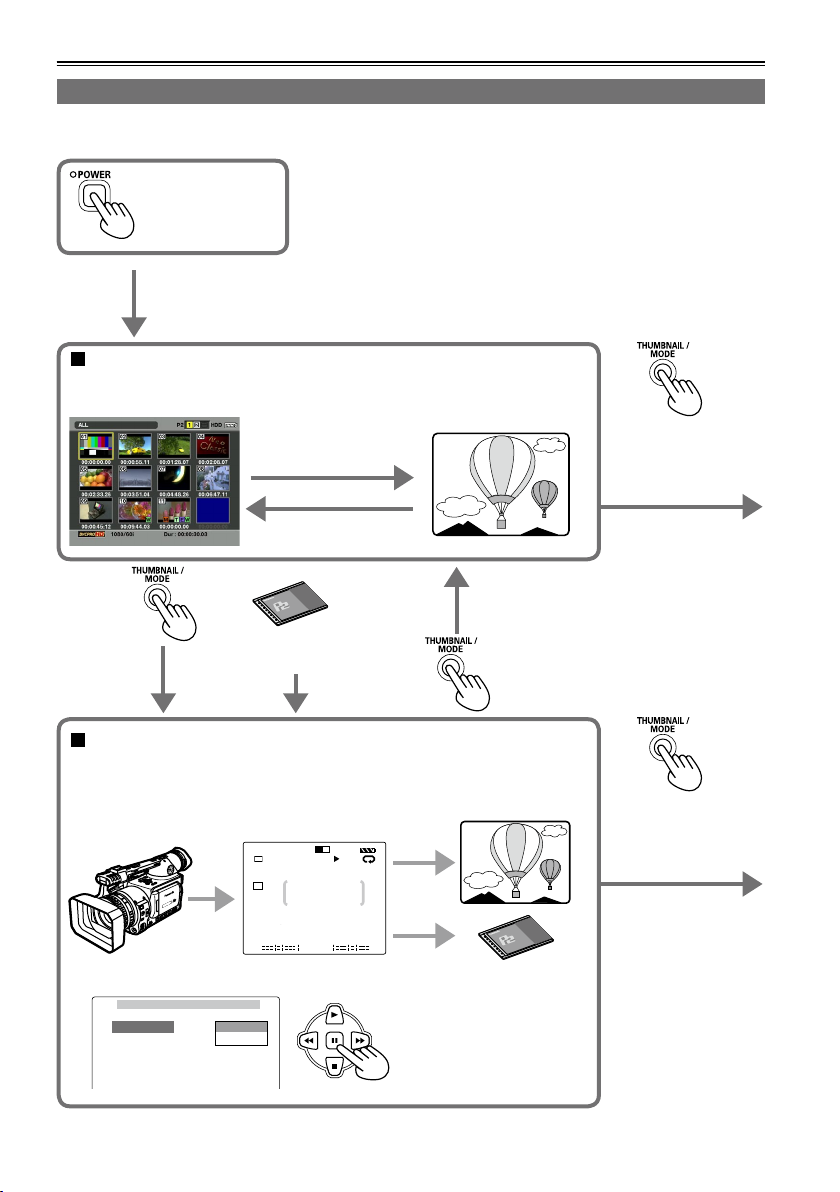
Operation modes
This unit has the following 3 modes which can be selected by pressing [THUMBNAIL/MODE].
Turn on the power.
Thumbnail display screen
On this screen, the data content on the P2 cards is displayed as
thumbnails to play back or manage the clips.
Playback
(PLAY, STILL, FF, REW)
Stop (STOP)
When a P2 card
has been ejected
Normal display screen
• Connect the unit to the devices equipped with the HD/SD-SDI input/
output or IEEE1394 connector, or set INT SG (Page 91) for playback and
recording.
Playback
Recording
• Display the menu, and perform the various settings.
Hold down this button
for at least 2 seconds
to switch to the PC
mode.
Hold down this button
for at least 2 seconds
to switch to the PC
mode.
24
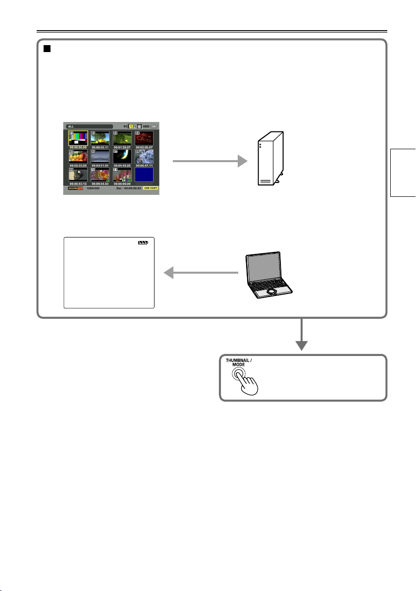
PC mode
Connect the unit to an external device, and save or manage the clips. Depending on the
connection method and purpose, the USB HOST mode and USB DEVICE mode are available;
perform the mode settings using the setting menu on the normal display screen.
• USB HOST mode
Connect to a device equipped with a USB connector, and operate the connected device.
• USB DEVICE mode
Connect to a device equipped with a USB connector, and operate the data on the unit’s P2 card
from the connected device.
USB DEVICE
Press and hold at least 2 seconds
to return to the thumbnail display
screen.
Preparations
25
DISPLAY SETUP
PUSH MENU TO RETURN
OSD OUT SEL
DATE/TIME
P2CARD REMAIN
OTHER DISPLAY
LCD BACKLIGHT
LEVEL METER
CARD/BATT
LCD SETTING
OFF
CH1-4
ON
LCD
ON
TOTAL
CHANGE
RETURN
LCD SETTING
LCD CONTRAST
LCD BRIGHTNESS
LCD COLOR LEVEL
PUSH MENU TO RETURN
[ + ]
[ + ]
[ + ]
[ ]
_
[ ]
_
[ ]
_
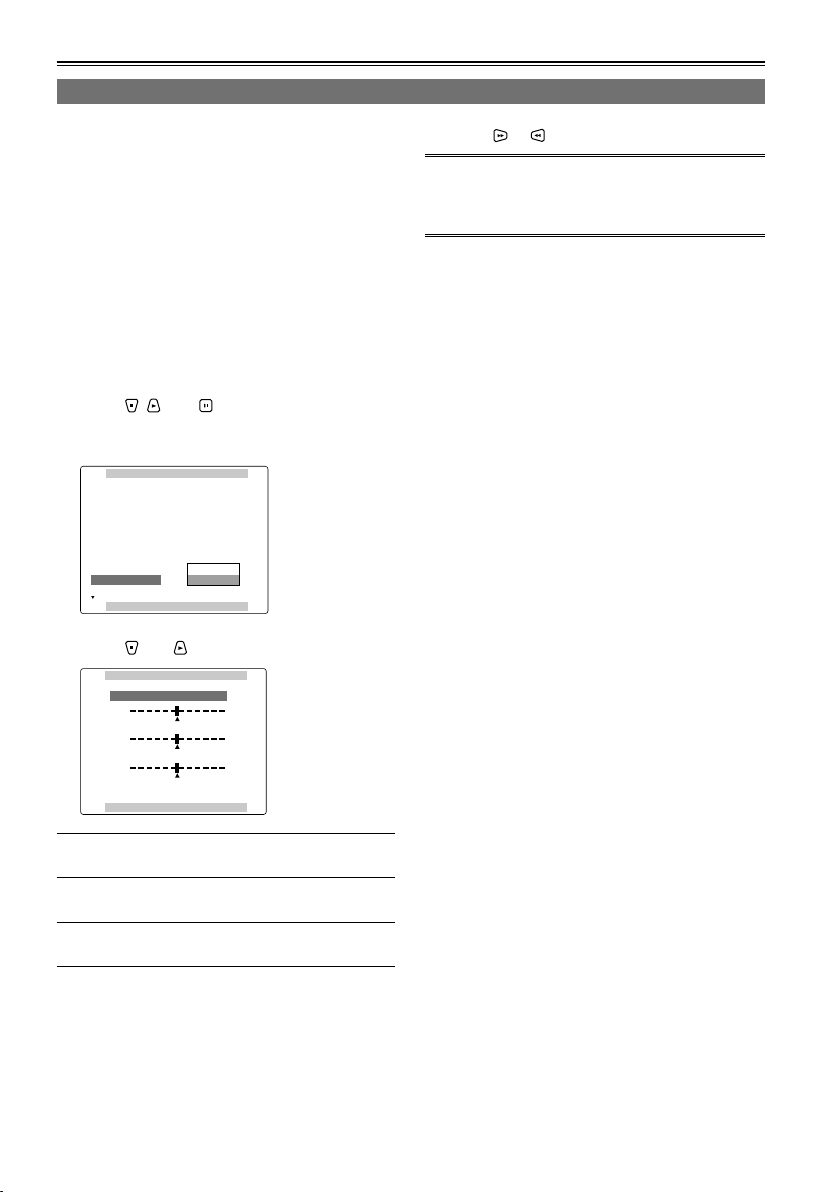
Basic operations (continued)
LCD monitor settings
1 Hold down [POWER] for at least 1 second to
turn the power on.
First check that an image is displayed on the
LCD monitor, and then adjust the angle of the
monitor to the position where it is easiest to see
its displays.
2 Press [THUMBNAIL/MODE] to display the
normal display screen.
3 Press [MENU/MODE CHK].
Basic operations on the setting menus (Page
•
88)
4 Using , , and , select “CHANGE” for
the “LCD SETTING” item on the setting
menu “DISPLAY SETUP” screen.
5 Using and , select the item to be set.
6 Using or , adjust the selected item.
When [RESET] is pressed, the adjusted values of
•
the selected items can be restored to their factory
settings.
7 Press [MENU/MODE CHK] 3 times to return
to the normal display screen.
LCD COLOR LEVEL:
LCD BRIGHTNESS:
LCD CONTRAST:
Note that if you set all LCD adjustment values to
•
This adjusts the color
density of the screen.
This adjusts the screen
brightness.
This adjusts the screen
contrast.
minimum, the menu screen will become difficult
to see.
26
OTHER FUNCTIONS
PUSH MENU TO RETURN
PC MODE SELECT
BEEP SOUND
CLOCK SETTING
TIME ZONE
POWER SAVE
SYSTEM FREQ
USER FILE
USB HOST
OFF
>>>
0:00
OFF
59.94Hz
>>>
OTHER FUNCTIONS
PUSH MENU TO RETURN
PC MODE SELECT
BEEP SOUND
CLOCK SETTING
TIME ZONE
POWER SAVE
SYSTEM FREQ
USER FILE
USB HOST
OFF
RETURN
OFF
59.94Hz
>>>
CHANGE
CLOCK SETTING
PUSH MENU TO RETURN
YEAR
DAY
MONTH
HOUR
MINUTE
APR
07
24
13
2009
+/ /
/
-
SEL
: PUSH
: PUSH
CLOCK SETTING
PUSH MENU TO RETURN
YEAR
DAY
MONTH
HOUR
MINUTE
APR
07
24
13
2009
+/ /
/
-
SEL
: PUSH
: PUSH
CLOCK SETTING
PUSH MENU TO RETURN
YEAR
DAY
MONTH
HOUR
MINUTE
MAY
07
24
13
2009
+/ /
/
-
SEL
: PUSH
: PUSH
CLOCK SETTING
PUSH MENU TO RETURN
YEAR
DAY
MONTH
HOUR
MINUTE
MAY
20
25
17
2009
+/ /
/
-
SEL
: PUSH
: PUSH
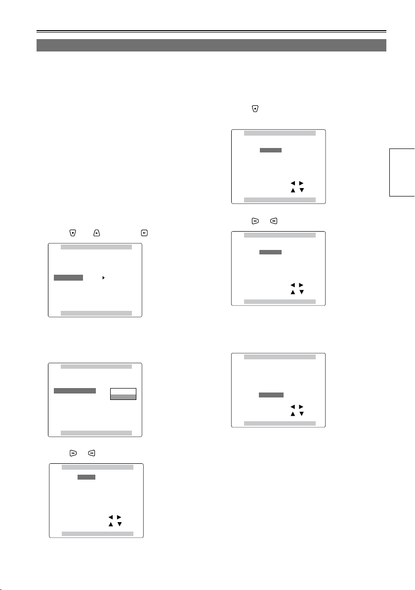
Setting date and time
The “CLOCK SETTING” value is recorded on the data content (clips), and it affects the sequence in which
the thumbnails are played back. Before recording, be absolutely sure to check the “CLOCK SETTING” and
“TIME ZONE” settings, and set them if necessary. Described below is the procedure for setting date and
time to 5:20 PM on May 25, 2009.
1 Hold down [POWER] for at least 1 second to
turn the power on.
2 Press [THUMBNAIL/MODE] to display the
normal display screen.
3 Press [MENU/MODE CHK].
Basic operations on the setting menus (Page
•
88)
4 At the “TIME ZONE” item on the setting
menu “OTHER FUNCTIONS”, change the
time difference from Greenwich Mean Time
using and , and press . (Page 106)
5 Select “CHANGE” for the “CLOCK
SETTING” item on the setting menu
“OTHER FUNCTIONS” screen.
7 Press to move the setting item to
“MONTH”.
8 Press or to set “MONTH” to “MAY”.
9 Use the same method as in steps 7 and 8 to
set “DAY”, “HOUR” and “MINUTE”.
The 24-hour clock system is used by this unit.
•
Preparations
6 Press or to set “YEAR” to “2009”.
Any year from 2000 to 2037 can be set.
10 Press [MENU/MODE CHK] 3 times to
return to the normal display screen.
There may be a time error. Check if the
•
CLOCK shows the correct time before
shooting.
If the unit is going to be used overseas, do
•
not set the “CLOCK SETTING” to the current
time but input the time difference from GMT
using the “TIME ZONE”.
27
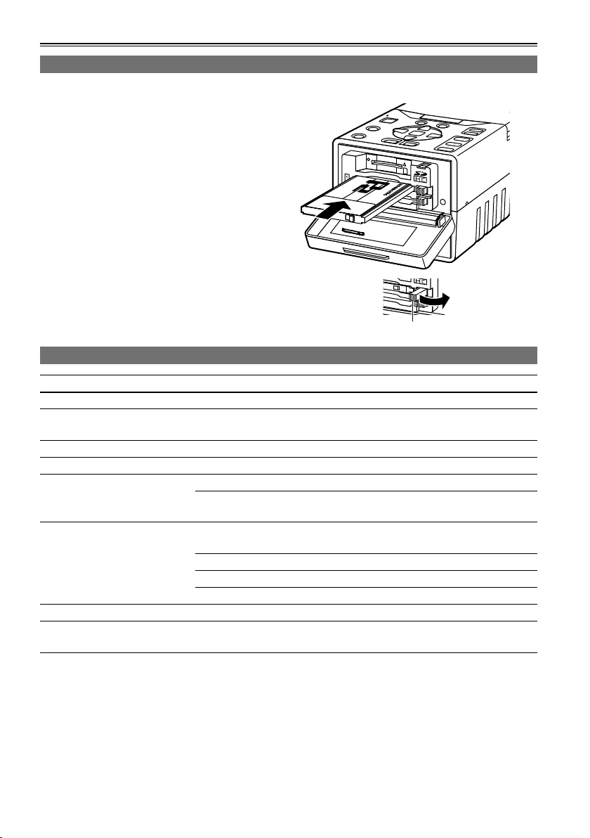
P2 cards
Inserting P2 cards
When the unit is to be used for the first time, the first step is always to set the internal clock. (Page 27)
1 Hold down [POWER] for at least 1 second to
turn the power on.
2 Open the card slot cover, and insert the P2
card into the P2 card slot as far as it will go.
Push further until the P2 card eject button
pops out.
When the P2 card is inserted into the unit, the
•
P2 card status is displayed by the P2 card
access LED.
For details on the P2 card status displayed,
refer to “P2 card access LED and P2 card
status” in the chart below.
3 Tip the popped-out P2 card eject button to
the right side and close the card slot cover.
P2 card access LED and P2 card status
P2 card access LED P2 card status
Lights up green Data can be saved on the card or loaded from the card.
Lights up orange
Blinks in orange Data is now being saved or loaded.
Blinks rapidly in orange The recognition process of the P2 card is underway.
Blinks in green
Off
Data can be saved on the card or loaded from the card, and currently
this card is supposed to be used for recording.
The P2 card is full. Data can be read out only.
The write-protect switch on the P2 card is at the PROTECT setting.
Data can be loaded only.
The P2 card has not been formatted properly. Re-format the card using
the unit.
The card cannot be used by the unit. Replace the card.
The P2 card is not installed.
The P2 card is not being accessed in the USB DEVICE mode.
P2 card eject button
The P2 card statuses can be checked in detail.
•
Refer to “Displaying the P2 card status” on page 54.
28
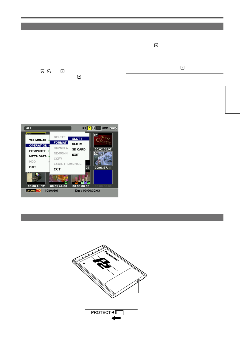
Formatting P2 cards
1 Hold down [POWER] for at least 1 second to
turn the power on.
The thumbnail screen now appears.
2 Press [MENU/MODE CHK].
3 Using , and , select “OPERATION”
– “FORMAT”, and press .
A screen such as the one shown below
•
now appears. Select the number of the slot
in which the P2 card to be formatted has
been inserted. If the card is not going to be
formatted, select “EXIT”.
If [MENU/MODE CHK] is pressed, the menu
•
display is cleared.
4 Select “YES” on the confirmation screen,
and press .
The selected P2 card is now formatted.
•
5 When the completion message has
appeared, press “OK” ( ).
If you format the P2 card, all the data saved on the
P2 card is deleted.
Preparations
P2 card protection
To prevent the data recorded on the P2 card from being deleted by mistake, set the write-protect switch on
the P2 card to PROTECT.
Write-protect
switch
29
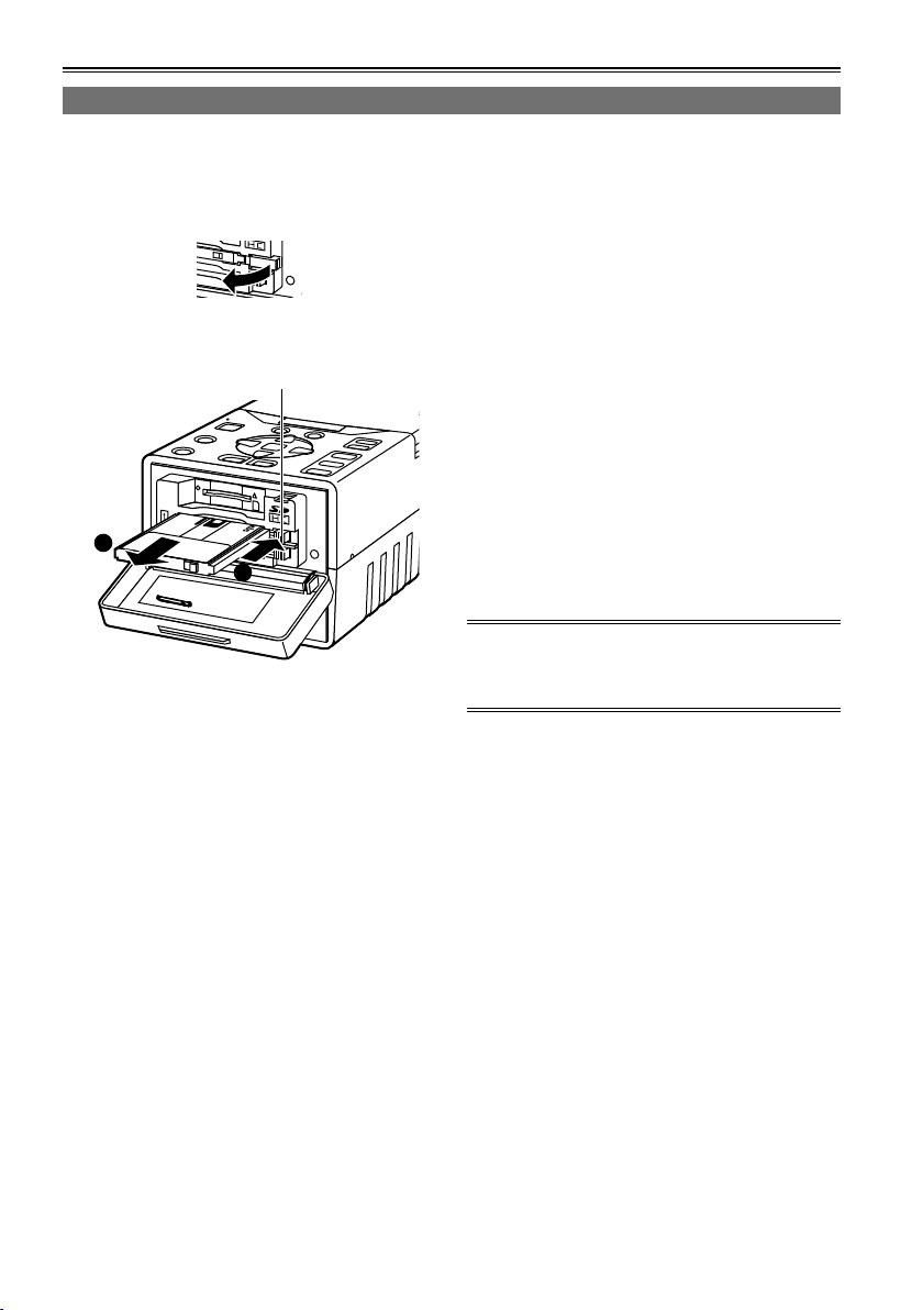
P2 cards (continued)
1
2
Ejecting P2 cards
1 Confirm P2 card access LED is not blinking
orange.
2 Open the card slot cover and raise the P2
card eject button.
3 Push the P2 card eject button to remove the
P2 card.
P2 card eject button
4 After ejecting the P2 card, close the card
slot cover.
Do not eject cards or turn off the power in the
•
following situations: otherwise, this may cause
P2 card trouble.
1) While the orange P2 card access LED is
changing from blinking to lighting after the P2
card has been inserted
2) During recording, during the process to
complete recording or while the P2 card
access LED is blinking
3) While the P2 card access LED is blinking
(i.e. while copying, formatting, etc.)
In the event that a P2 card is ejected while being
•
accessed or formatted, “TURN POWER OFF” is
displayed on the LCD monitor. In a case like this,
turn the power off and then turn it back on.
When a card was ejected while it was being
formatted:
Re-format the card.
When a card was ejected while its data was
being accessed:
Something may have gone wrong with one of the
clips (Page 35). Check the clips, and repair the
abnormal one. (For details on repairing clips →
Page 41)
During playback, a P2 card will not be recognized
•
even if it has been inserted into the other empty
slot, and the P2 card access LED will not
light. After playback is completed, the P2 card
recognition process is started.
If the P2 card is ejected while thumbnails are
•
displayed, the thumbnail display screen will be
cleared and the normal display screen appears.
Precaution for using P2 cards
P2 cards must always be formatted using a P2
device prior to use.
30
 Loading...