

Page 1

Panasonic Broadcast
AG-HPG10
Menu Information
Page 2
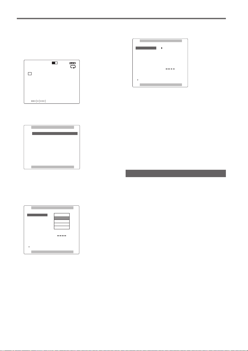
Basic operations on the setting menus
Hold down [POWER] for at least 2 seconds
1
to turn the power on.
2 Press [MODE] to switch to the thumbnail
display off screen.
1 2
106 mn
HD720P
60
C
1
H
C
2
H
3 Press [MENU] to display the menu.
Example:
MAIN MENU
1 .
RECORDING SETUP
SW MODE
2 .
3 . PLAYBACK FUNCTIONS
4 . AV OUT SETUP
5 . DISPLAY SETUP
6 . CARD FUNCTIONS
7 . OTHER FUNCTIONS
PUSH MENU TO EXIT
4 Using [STOP] and [PLAY], move the
highlighting to the function to be set.
5 Press [STILL] to display the setting item.
Example:
RECORDING SETUP
SYS FORMAT
SD(480i/576) MODE
1394 TC REGEN
TC MODE
TCG
TC PRESET
1394 UB REGEN
UB MODE
PUSH MENU TO RETURN
1080i/60i
720P/60P
720P/30PN
720P/24PN
480i/60i
REC RUN
ON
FRM.RATE
6 Using [STOP] and [PLAY] , move to the item
to be set.
RECORDING SETUP
SYS FORMAT
SD(480i/576) MODE
1394 TC REGEN
TC MODE
TCG
TC PRESET
1394 UB REGEN
UB MODE
PUSH MENU TO RETURN
720P/60P
DV
ON
DF
REC RUN
ON
FRM.RATE
7 Press [STILL] to set the item.
To change a numerical value, etc., use [FF] and
[REW] to change the setting.
8 To change other items, repeat steps 6 and 7.
To exit the settings, press [MENU] and return to
the thumbnail display off screen.
9 To change another function, repeat steps 4
to 7.
To exit the settings, press [MENU] and return to
the thumbnail display off screen.
Initializing the setting menu
You can return (initialize) the setting menu user
files to the factory status.
1 Switch the display to the thumbnail display
off screen.
2 Press [MENU].
3 Using [STOP], [PLAY] and [STILL], select
“OTHER FUNCTIONS” – “USER FILE”
– “INITIAL”.
4 Press [STILL].
The menu settings of the user files currently
being used are returned to the factory status.
70
Page 3
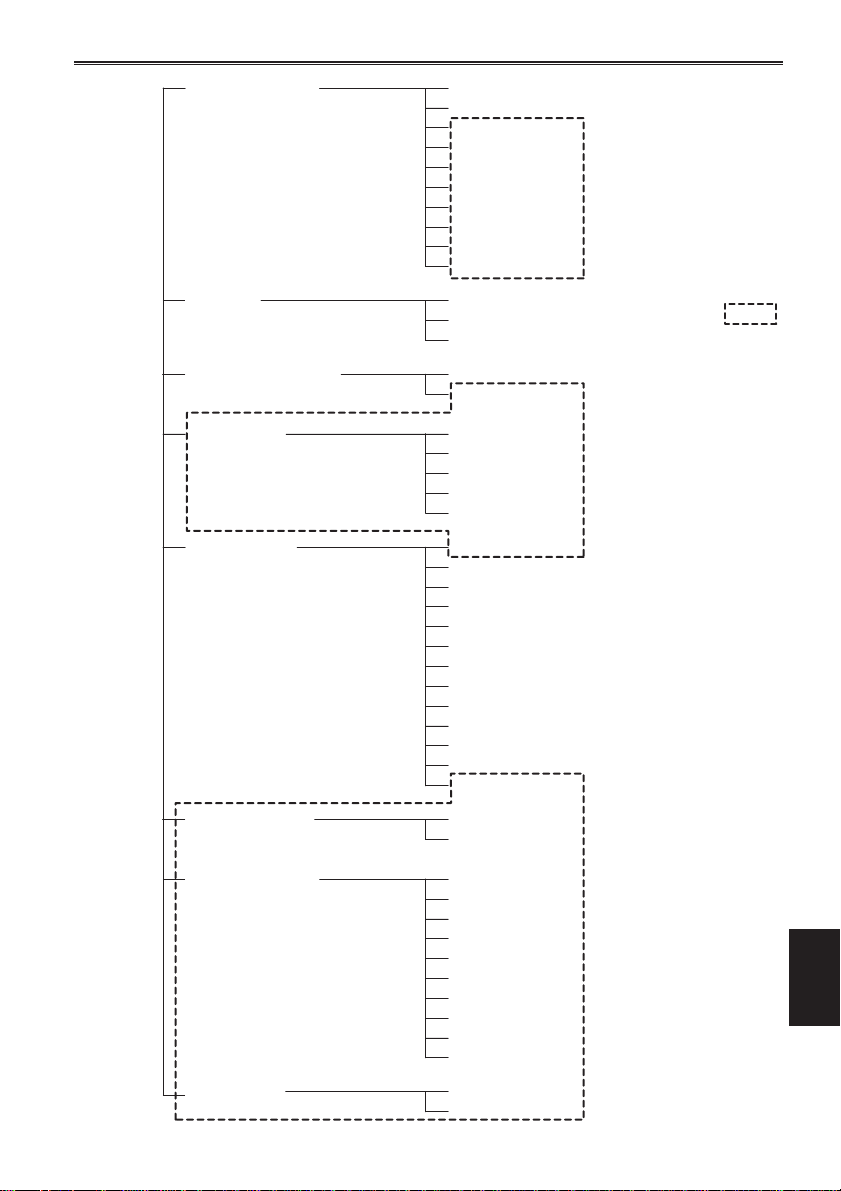
Setting menu configuration
RECORDING SETUPMAIN MENU
(Pages 72 - 73)
SW MODE
(Page 74)
PLAYBACK FUNCTIONS
(Page 75)
AV OUT SETUP
(Page 75)
DISPLAY SETUP
(Pages 76 - 77)
SYS FORMAT
SD(480i/576)MODE
1394 TC REGEN
TC MODE
TCG
TC PRESET
1394 UB REGEN
UB MODE
UB PRESET
1394 IN PRESET
USER1
USER2
USER3
REPEAT PLAY
AUDIO OUT
CMPNT/SDI SEL
SDI OUT
SDI METADATA
SDI EDH
SETUP
VIDEO OUT OSD
DATE/TIME
LEVEL METER
CARD/BATT
P2 CARD REMAIN
OTHER DISPLAY
LCD BACKLIGHT
LCD REVERSE
LCD SET
LCD ASPECT
MENU BACK
DOWNCON MODE
WFM
Menus enclosed in the
broken-line frames
are not displayed in the
USB HOST mode.
CARD FUNCTIONS
(Page 77)
OTHER FUNCTIONS
(Pages 78 - 79)
OPTION MENU
(Page 80)
USER FILE
SD CARD FORMAT
PC MODE
BEEP SOUND
CLOCK SET
TIME ZONE
POWER SAVE
LANGUAGE
SYSTEM FREQ
USER FILE
OPERATION
LCD OPERATION
1394 STATUS
1394 CONFIG
Menu
71
Page 4
List of setting menus
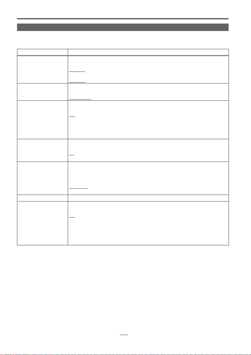
RECORDING SETUP screen
When the settings are changed using the “SYSTEM FREQ” item (page 79) on the “OTHER FUNCTIONS”
screen, whatever has been set on the “RECORDING SETUP” screen will be changed to the initial setting.
Item Description of settings
SYS FORMAT This is used to set the 1394 input recording format and playback format.
SD(480i/576) MODE This is used to set the 1394 input recording video compression format and playback
1394 TC REGEN This is used to select the time code to be recorded when recording signals from a
TC MODE (60 Hz regions
only)
TCG This is used to set the operation mode for running the time code of the internal time
TC PRESET This is used to set the initial value of the time code to be recorded.
1394 UB REGEN This is used to set the recording of the user’s bit when recording input signals from a
(60 Hz)
1080/60i, 720/60P, 720/30PN, 720/24PN, 480/60i
(50 Hz)
1080/50i, 720/50P, 720/25PN, 576/50i
format.
DVCPRO50, DVCPRO, DV
device which is connected to the 1394 connector.
ON:
The data is recorded using the time code of the signals supplied to the 1394
connector.
OFF:
The data is recorded using the time code set using the TC MODE item or TCG item.
This is used to select the time code compensation mode when recording the time
codes of the internal time code generator.
DF: The drop frame mode is used.
NDF: The non-drop frame mode is used.
code generator.
FREE RUN:
The time code runs no matter what operating mode is established.
REC RUN:
The time code runs only during recording.
device which is connected to the 1394 connector.
ON:
The signals are recorded using the user’s bit of the signals supplied to the 1394
connector.
OFF:
The signals are recorded using the user’s bit selected by the UM MODE item.
When this item has been set to ON, it takes priority over the UB MODE item.
72
The underlined settings are the factory mode settings.
Page 5

RECORDING SETUP screen (continued)
Item Description of settings
UB MODE This is used to set what is to be recorded as the user’s bit.
USER:
The user information is recorded.
TIME:
The time of the recording is recorded.
DATE:
The date/time of the recording are recorded.
TCG:
The value generated by the time code generator is recorded.
FRM. RATE:
The information of the frame rate after frame conversion is recorded.
a: Information on the verification of the user’s bit value
b: Frame sequence number
•“F” is displayed in the 60i/30P mode.
c: Frame rate information
• Frame rate (60, 30 or 24)
• I/P identification information
• Conversion information
• Frame rate factor
d: Recording control information
• Update frame information
• REC START/STOP information
Note
When playing back native recorded clips
To set the 1394 output user’s bit as the frame rate information, select FRM. RATE for
this setting, and play back the clips. If this is the case, the user’s bit displayed on the
screen will also be changed to the frame rate information.
UB PRESET This is used to set the user’s bit. However, USER must be selected as the UB MODE
1394 IN PRESET When [RESET/TC SET] is pressed, the value generated by the internal time code
item setting.
generator is synchronized with the 1394 input time code.
ON:
The 1394 input synchronization setting mode is established.
OFF:
The 1394 input synchronization setting mode is released.
ab cd
The underlined settings are the factory mode settings.
Menu
73
Page 6

List of setting menus (continued)
SW MODE screen
Item Description of settings
USER1 This is used to set which function is to be assigned to the USER1 button.
USER2 This is used to set which function is to be assigned to the USER2 button.
USER3 This is used to set which function is to be assigned to the USER3 button.
SYS FORMAT:
System format (page 72)
SD MODE :
SD mode (page 72)
SHOT MARK :
A shot mark is recorded on the clip. (Page 39)
TEXT MEMO :
A text memo is recorded. (Page 38)
LCD BL :
LCD backlight (page 76)
V OUT OSD :
Video output on-screen display (page 76)
AUDIO OUT :
Audio output (page 75)
SLOT SEL :
P2 card slot selection (page 49)
LCD RVS :
LCD reverse (page 76)
WFM :
Waveform monitor (page 49)
The settings of this item are the same as the USER1 item settings.
SHOT MARK
The settings of this item are the same as the USER1 item settings.
TEXT MEMO
74
The underlined settings are the factory mode settings.
Page 7

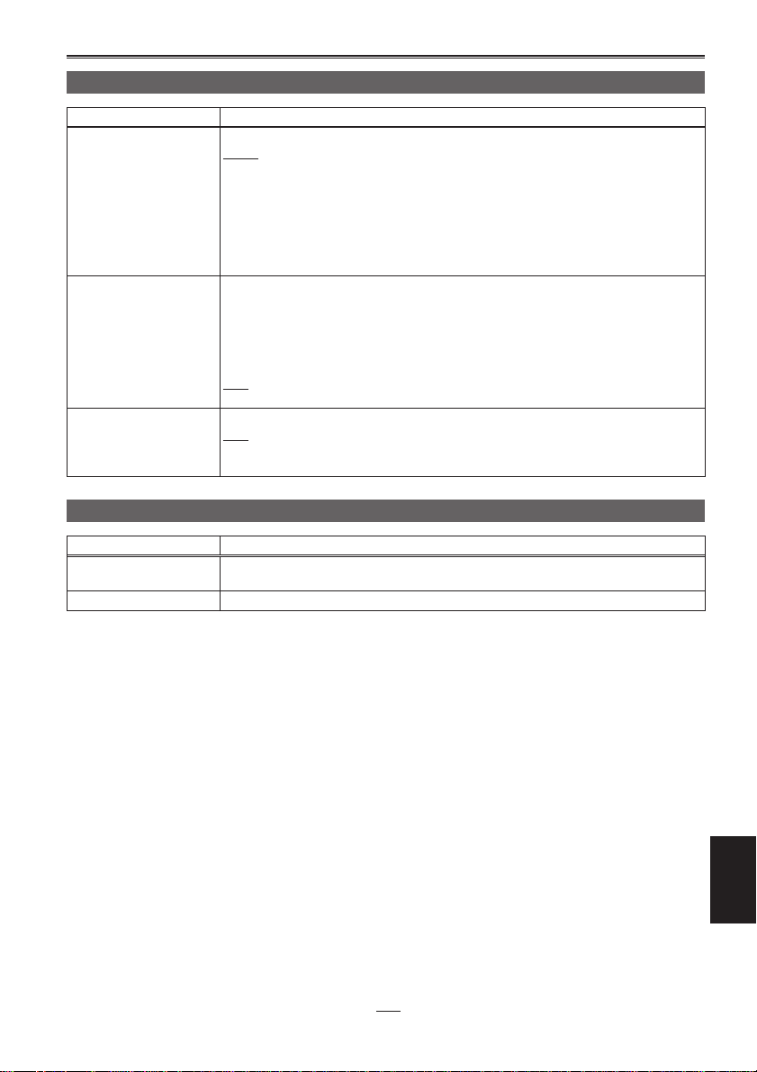
PLAYBACK FUNCTIONS screen
Item Description of settings
REPEAT PLAY This is used to set repeat playback.(Page 43)
AUDIO OUT This is used to set the audio signals to be output from the AUDIO OUT connectors
ON: Playback is repeated.
OFF: Playback is not repeated.
(pin jacks) during playback.
CH1 · CH2:
CH1 connector = CH1 signal, CH2 connector = CH2 signal,
CH1:
CH1 connector = CH1 signal, CH2 connector = CH1 signal,
CH2:
CH1 connector = CH2 signal, CH2 connector = CH2 signal,
CH3 · CH4:
CH1 connector = CH3 signal, CH2 connector = CH4 signal,
CH3:
CH1 connector = CH3 signal, CH2 connector = CH3 signal,
CH4:
CH1 connector = CH4 signal, CH2 connector = CH4 signal,
AV OUT SETUP screen
Item Description of settings
CMPNT/SDI SEL This is used to set the format when D connector signals and HD/SD-SDI signals are
SDI OUT This is used to set the SDI output.
SDI METADATA This is used to set whether to superimpose the meta-data when HD-SDI signals are
SDI EDH This is used to set whether to superimpose error detection handling (EDH) when SD-
SETUP
(60 Hz regions only)
output.
(60 Hz regions)
AUTO:
Operation reflects the setting selected for the SYS FORMAT item on the
RECORDING SETUP screen.
1080i, 480i
(50 Hz regions)
AUTO:
Operation reflects the setting selected for the SYS FORMAT item on the
RECORDING SETUP screen.
1080i, 576i
ON: SDI signals are output.
OFF: SDI signals are not output.
output.
ON: The meta-data is superimposed.
OFF: The meta-data is not superimposed.
SDI signals are output.
ON: EDH is superimposed.
OFF: EDH is not superimposed.
The setup level of the video signals during playback is set.
0%:
0% is set as the output setup level.
7.5%A:
7.5%A is set as the output setup level.
Menu
The underlined settings are the factory mode settings.
75
Page 8

List of setting menus (continued)
DISPLAY SETUP screen
Item Description of settings
VIDEO OUT OSD When ON is selected as this item’s setting, the information displayed on the LCD
DATA/TIME This is used to select the setting for displaying the date and time on the LCD monitor
LEVEL METER This is used to set the audio level meter display to ON or OFF.
CARD/BATT This is used to set the amount of memory remaining on the card and charge level
P2 CARD REMAIN This is used to set how the amount of memory remaining on the P2 card is to be
OTHER DISPLAY This is used to set the amount of information to be displayed on the LCD monitor.
LCD BACKLIGHT This is used to adjust the backlight of the LCD monitor. The backlight becomes
LCD SET This is used to adjust the display level of the images on the LCD monitor. (Page 22)
LCD REVERSE This is used to set the function for reversing the top/bottom and left/right of the images
DOWNCON MODE This is used to set the down-converter output signal mode.
monitor is output as a video output signal together with the video signals. (Component
output signals, VIDEO output signals, SDI output signals)
ON, OFF
and video output signals.
OFF:
The date and time are not displayed.
TIME:
The time is displayed.
DATE:
The date is displayed.
TIME&DATE:
The date and time are displayed.
ON, OFF
remaining in the battery to ON or OFF.
ON, OFF
calculated.
ONE-CARD:
The amount of memory remaining on the P2 card in the selected slot is calculated.
TOTAL:
The amount of memory remaining on the P2 cards in both slots is calculated.
(Page 73)
OFF, PARTIAL, ALL
brighter than usual when HIGH is selected.
HIGH, NORMAL
LCD COLOR LEVEL
LCD BRIGHTNESS
LCD CONTRAST
displayed on the LCD monitor.
NORM:
The images are displayed normally.
REVERSE:
The images are displayed with their top/bottom and left/right reversed.
• The direction in which the menu highlighting moves and the direction of the cursor
movement on the thumbnail display screen cannot be reversed in either the up/
down or left/right direction.
SIDE CROP, LETTER-BOX, SQUEEZE
76
The underlined settings are the factory mode settings.
Page 9
DISPLAY SETUP screen (continued)
Item Description of settings
LCD ASPECT This is used to select the aspect ratio for the LCD monitor.
MENU BACK This is used to reduce the transmittance of the background behind the menu
WFM This is used to select what is to be displayed on the waveform monitor.
AUTO:
The aspect ratio is automatically selected based on the recording mode, playback
mode and other information.
4:3:
The aspect ratio is fixed at 4:3.
Note
When images are displayed with the 16:9 aspect ratio, black bands appear at the top
and bottom of the screen. No parts of the images are missing.
display screen so that the menu characters can be seen more easily.
ON:
The background transmittance is reduced.
• This transmittance is not reduced while the LCD SET item on the DISPLAY SETUP
screen is being set.
OFF:
The background transmittance is 100%.
OFF: No display
WAVE: Waveforms are displayed.
VECTOR: Vectors are displayed.
CARD FUNCTIONS screen
Item Description of settings
USER FILE Up to four sets of menu item settings can be saved on the SD memory card. Titles
SD CARD FORMAT This is used to format SD memory cards.
can be given to the files which have been saved.
The underlined settings are the factory mode settings.
Menu
77
Page 10

List of setting menus (continued)
OTHER FUNCTIONS screen
Item Description of settings
PC MODE This is used to select the connectors and mode to be used for data transfer. (The USB
BEEP SOUND This is used to set the beep sound to ON or OFF.
CLOCK SET This is used to set the unit’s internal calendar.
TIME ZONE The time is set in 30-minute increments from 12:00 hours behind GMT to 13:00 hours
and 1394 connectors cannot be used at the same time.)
USB DEVICE:
File transfer mode using the USB connector
USB HOST:
In this mode, files are copied on an external hard disk from the P2 card using the
USB connector.
1394 DEVICE:
File transfer mode using the 1394 connector
1394 HOST:
In this mode, files are copied on an external hard disk from the P2 card using the
1394 connector.
ON, OFF
ahead of GMT (a setting of 12:45 hours ahead is also available). (Refer to the table
below.)
+9:00
Time
difference
(from GMT)
00:00 Greenwich – 00:30
– 01:00 Azores – 01:30
– 02:00 Central Atlantic – 02:30
– 03:00 Buenos Aires – 03:30 Newfoundland
– 04:00
– 05:00 New York – 05:30
– 06:00 Chicago – 06:30
– 07:00 Denver – 07:30
– 08:00 Los Angeles – 08:30
– 09:00 Alaska – 09:30 Marquesas Islands
– 10:00 Hawaii – 10:30
– 11:00 Midway Islands – 11:30
– 12:00 Kwajalein Atoll + 11:30 Norfolk Islands
+ 13:00 + 10:30 Lord Howe Island
+ 12:00 New Zealand + 09:30 Darwin Islands
+ 11:00 Solomon Islands + 08:30
+ 10:00 Guam + 07:30
+ 09:00 Tokyo + 06:30 Rangoon
+ 08:00 Beijing + 05:30 Mumbai (Bombay)
+ 07:00 Bangkok + 04:30 Kabul
+ 06:00 Dhaka + 03:30 Teheran
+ 05:00 Islamabad + 02:30
+ 04:00 Abu Dhabi + 01:30
+ 03:00 Moscow + 00:30
+ 02:00 Eastern Europe + 12:45 Chatham Islands
+ 01:00 Central Europe
Region (city)
Halifax (Nova
Scotia)
Time
difference
(from GMT)
– 04:30
Region (city)
78
The underlined settings are the factory mode settings.
Page 11

OTHER FUNCTIONS screen (continued)
Item Description of settings
POWER SAVE This is used to select the power-saving mode which is to be established when none of
LANGUAGE This is used to set the language in which the menu is to be displayed.
SYSTEM FREQ This is used to set the system frequency in line with NTSC or PAL.
USER FILE LOAD:
OPERATION This is used to display the power-on time (using 5 digits).
LCD OPERATION This is used to display the power-on time (using 5 digits) for the backlight of the LCD
the function keys or buttons have been operated for 5 or so minutes.
ON:
The unit’s power is turned off.
OFF:
The unit remains in the stop mode without turning off its power.
• While the unit is connected by an IEEE1394 cable or USB cable to an external
device and communicating with it, the power will not be turned off even if the
function keys or buttons have not been operated for the prescribed period of time.
• Even when ON is selected as this item’s setting, the power will not be turned off
during playback (PLAY, CUE (rapid forward), REV (rapid reverse), FF, REW or
STILL) or during recording.
ENGLISH: English
JAPANESE: Japanese
CHINESE: Chinese
59.9 Hz, 50 Hz
The settings of the user files last saved are loaded.
SAVE:
The settings of the user files which have been changed are stored.
INITIAL:
The user file settings are returned to the factory settings.
In order for the settings to take effect after loading or initializing, turn off the unit’s
power and turn it back on.
• Even when initializing has been performed, the TIME ZONE item (page 80) will
remain unchanged.
monitor.
The underlined settings are the factory mode settings.
Menu
79
Page 12

List of setting menus (continued)
OPTION MENU screen
This screen appears when [MENU] are pressed while [STOP] is held down on the thumbnail display off
screen.
Item Description of settings
1394 STATUS The 1394 status display sub-screen is displayed.
1394 CONFIG The 1394 expansion menu is displayed.
FORMAT:
Format of the input or output signals
RATE:
Transfer rate of the input or output signals
60/50:
System of input or output signals
CH:
Value of the channels whose signals are input or output
SPEED:
Transfer speed of the input or output signals
STATUS:
Status of the signals which are input or output by the IEEE1394 digital interface
VIDEO:
Status of the input or output video signals
AUDIO:
Status of the input or output audio signals
DFLT:
For normal operation, keep this setting.
1-255
80
The underlined settings are the factory mode settings.
 Loading...