

Page 1
■ This product is eligible for the P2HD 5 Ye ar
Warranty Repair Program. For details,
see page 90 of Vol.2.
Operating Instructions
Memory Card Portable Recorder
Model No.AG-HPD24P
Model No.AG-HPD24E
1
Volume
Note that Operation Instructions Vol.1 describes basic operations
of the Memory Card Portable Recorder.
For instructions on advanced operations of the Memory Card
Portable Recorder, refer to Operating Instructions Vol. 2 (pdf file)
contained in the supplied CD-ROM.
Vol.1
Before operating this product, please read the instructions carefully and save this manual
for future use.
SS0711TO0 -PS
Printed in japan
ENGLISH
VQT3S21
Page 2
Read this first! (For AG-HPD24P)
CAUTION:
The mains plug of the power supply cord
shall remain readily operable.
The AC receptacle (mains socket outlet)
shall be installed near the equipment and
shall be easily accessible.
To completely disconnect this equipment
from the AC mains, disconnect the mains
plug from the AC receptacle.
CAUTION:
Danger of explosion or fire if battery is
incorrectly replaced or mistreated.
• Do not disassemble the battery or dispose
of it in fire.
• Do not store in temperatures over 60 °C
(140 °F).
WARNING:
This equipment must be grounded.
To ensure safe operation, the three-pin plug
must be inserted only into a standard threepin power outlet which is effectively
grounded through normal household wiring.
Extension cords used with the equipment must
have three cores and be correctly wired to
provide connection to the ground. Wrongly wired
extension cords are a major cause of fatalities.
The fact that the equipment operates
satisfactorily does not imply that the power outlet
is grounded or that the installation is completely
safe. For your safety, if you are in any doubt
about the effective grounding of the power
outlet, please consult a qualified electrician.
WARNING:
• To reduce the risk of fire or electric shock,
do not expose this equipment to rain or
moisture.
• To reduce the risk of fire or electric shock
hazard, keep this equipment away from all
liquids. Use and store only in locations
which are not exposed to the risk of dripping
or splashing liquids, and do not place any
liquid containers on top of the equipment.
WARNING:
Always keep memory cards (optional accessory)
out of the reach of babies and small children.
• Do not expose the battery to excessive
heat such as sunshine, fire or the like.
For Battery Pack
• Use specified charger.
• Replace only with same or specified type.
CAUTION:
In order to maintain adequate ventilation, do
not install or place this unit in a bookcase, builtin cabinet or any other confined space. To
prevent risk of electric shock or fire hazard due
to overheating, ensure that curtains and any
other materials do not obstruct the ventilation.
CAUTION:
To reduce the risk of fire or electric shock
and annoying interference, use the
recommended accessories only.
CAUTION:
This apparatus can be operated at a voltage
in the range of 100 – 240 V AC.
Voltages other than 120 V are not intended
for U.S.A. and Canada.
Operation at a voltage other than 120 V AC
may require the use of a different AC plug.
Please contact either a local or foreign
Panasonic authorized service center for
assistance in selecting an alternate AC plug.
CAUTION:
Excessive sound pressure from earphones
and headphones can cause hearing loss.
indicates safety information.
2
Page 3
Read this first! (For AG-HPD24P) (continued)
indicates safety information.
FCC NOTICE (USA)
Declaration of Conformity
Model Number: AG-HPD24P
Trade Name: Panasonic
Responsible Party: Panasonic Corporation of North America One Panasonic Way,
Support contact: 1-800-524-1448
This device complies with Part 15 of the FCC Rules.
Operation is subject to the following two conditions:
(1) This device may not cause harmful interference, and (2) this device must accept any
interference received, including interference that may cause undesired operation.
To assure continued compliance, follow the attached installation instructions and do not make
any unauthorized modifications.
CAUTION:
This equipment has been tested and found to comply with the limits for a Class B digital device,
pursuant to Part 15 of the FCC Rules. These limits are designed to provide reasonable protection
against harmful interference in a residential installation. This equipment generates, uses and can
radiate radio frequency energy and, if not installed and used in accordance with the instructions,
may cause harmful interference to radio communications. However, there is no guarantee that
interference will not occur in a particular installation. If this equipment does cause harmful
interference to radio or television reception, which can be determined by turning the equipment off
and on, the user is encouraged to try to correct the interference by one of the following measures:
• Reorient or relocate the receiving antenna.
• Increase the separation between the equipment and receiver.
• Connect the equipment into an outlet on a circuit different from that to which the receiver is
connected.
• Consult the dealer or an experienced radio/TV technician for help.
The user may find the booklet “Something About Interference” available from FCC local regional
offices helpful.
FCC Warning:
To assure continued FCC emission limit compliance, follow the attached installation instructions
and the user must use only shielded interface cables when connecting to host computer or
peripheral devices. Also any unauthorized changes or modifications to this equipment could
void the user’s authority to operate this device.
NOTIFICATION (Canada)
This class B digital apparatus complies with Canadian ICES-003.
Secaucus, NJ 07094
A lithium ion/polymer battery that is recyclable powers the product you have purchased.
Please call 1-800-8-BATTERY for information on how to recycle this battery.
Notice (U.S.A. only):
Disposal may be regulated in your community due to Environmental considerations. For disposal or recycling
information, please visit Panasonic website: http://www.panasonic.com/environmental or call 1-888-769-0149.
Note:
Recorder
The rating plate is on the underside of the recorder.
AC Adaptor
The rating plate is on the underside of the AC Adaptor. Disconnect the AC mains plug from the AC
mains socket when not in use.
3
Page 4
Read this first! (For AG-HPD24P) (continued)
Brazil Only
Brasil Apenas
■ Manuseio de baterias usadas
BRASIL
Após o uso, as pilhas e /ou baterias poderão ser entregues ao estabelecimento
comercial ou rede de assistência técnica autorizada.
Cobrir os terminais positivo (+) e negativo (-) com uma fita isolante adesiva, antes de depositar
numa caixa destinada para o recolhimento. O contato entre partes metálicas pode causar
vazamentos, gerar calor, romper a blindagem e produzir fogo.
Não desmonte, não remova o invólucro, nem amasse a bateria. O gás liberado pela bateria pode
irritar a garganta, danificar o lacre do invólucro ou o vazamento provocar calor, ruptura da
blindagem e produzir fogo devido ao curto circuito dos terminais.
Não incinere nem aqueça as baterias, elas não podem ficar expostas a temperaturas superiores
a 100 °C (212 °F). O gás liberado pela bateria pode irritar a garganta,danificar o lacre do invólucro
ou o vazamento provocar calor, ruptura da blindagem e produzir fogo devido ao curto circuito dos
terminais provocado internamente.
Evite o contato com o liquido que vazar das baterias. Caso isto ocorra, lave bem a parte afetada
com bastante água. Caso haja irritação, consulte um médico.
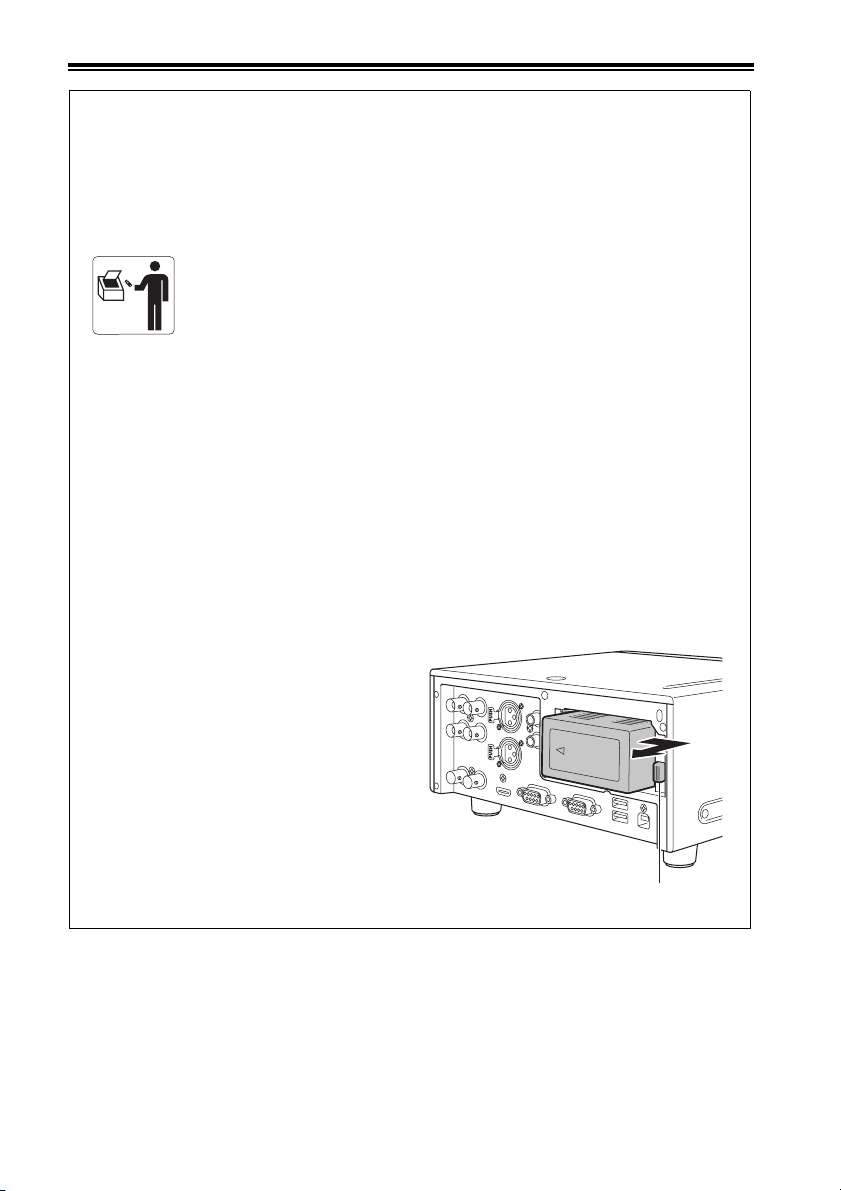
■ Para remover a bateria
Bateria Principal de Energia
Pressione o botão para liberar a bateria.
4
Botão de liberação da bateria
Page 5

Read this first! (For AG-HPD24P) (continued)
IMPORTANT SAFETY INSTRUCTIONS
1) Read these instructions.
2) Keep these instructions.
3) Heed all warnings.
4) Follow all instructions.
5) Do not use this apparatus near water.
6) Clean only with dry cloth.
7) Do not block any ventilation openings. Install in accordance with the manufacturer’s instructions.
8) Do not install near any heat sources such as radiators, heat registers, stoves, or other apparatus
(including amplifiers) that produce heat.
9) Do not defeat the safety purpose of the polarized or grounding-type plug. A polarized plug has two
blades with one wider than the other. A grounding-type plug has two blades and a third grounding
prong. The wide blade or the third prong are provided for your safety. If the provided plug does not
fit into your outlet, consult an electrician for replacement of the obsolete outlet.
10) Protect the power cord from being walked on or pinched particularly at plugs, convenience
receptacles, and the point where they exit from the apparatus.
11) Only use attachments/accessories specified by the manufacturer.
12) Use only with the cart, stand, tripod, bracket, or table specified by the manufacturer, or
sold with the apparatus. When a cart is used, use caution when moving the cart/apparatus
combination to avoid injury from tip-over.
13) Unplug this apparatus during lightning storms or when unused for long periods of time.
14) Refer all servicing to qualified service personnel. Servicing is required when the apparatus has been
damaged in any way, such as power-supply cord or plug is damaged, liquid has been spilled or
objects have fallen into the apparatus, the apparatus has been exposed to rain or moisture, does not
operate normally, or has been dropped.
S3125A
5
Page 6
Read this first! (For AG-HPD24E)
indicates safety information.
WARNING:
This equipment must be earthed.
To ensure safe operation, the three-pin plug
must be inserted only into a standard threepin power point which is effectively earthed
through normal household wiring.
Extension cords used with the equipment
must have three cores and be correctly
wired to provide connection to the earth.
Wrongly wired extension cords are a major
cause of fatalities.
The fact that the equipment operates
satisfactorily does not imply that the power
point is earthed or that the installation is
completely safe. For your safety, if you are
in any doubt about the effective earthing of
the power point, please consult a qualified
electrician.
WARNING:
• To reduce the risk of fire or electric shock, do
not expose this equipment to rain or moisture.
• To reduce the risk of fire or electric shock
hazard, keep this equipment away from all
liquids. Use and store only in locations
which are not exposed to the risk of dripping
or splashing liquids, and do not place any
liquid containers on top of the equipment.
WARNING:
Always keep memory cards (optional
accessory) out of the reach of babies and
small children.
CAUTION:
To reduce the risk of fire or electric shock
and annoying interference, use the
recommended accessories only.
CAUTION:
Do not remove panel covers by unscrewing
them.
To reduce the risk of electric shock, do not
remove the covers. No user serviceable
parts inside.
Refer servicing to qualified service personnel.
CAUTION:
In order to maintain adequate ventilation, do
not install or place this unit in a bookcase, builtin cabinet or any other confined space. To
prevent risk of electric shock or fire hazard due
to overheating, ensure that curtains and any
other materials do not obstruct the ventilation.
CAUTION:
Danger of explosion or fire if battery is
incorrectly replaced or mistreated.
• Do not disassemble the battery or dispose
of it in fire.
• Do not store in temperatures over 60 °C.
• Do not expose the battery to excessive
heat such as sunshine, fire or the like.
For Battery Pack
• Use specified charger.
• Replace only with same or specified type.
CAUTION:
The mains plug of the power supply cord
shall remain readily operable.
The AC receptacle (mains socket outlet)
shall be installed near the equipment and
shall be easily accessible.
To completely disconnect this equipment
from the AC mains, disconnect the mains
plug from the AC receptacle.
CAUTION:
Excessive sound pressure from earphones
and headphones can cause hearing loss.
The rating plate is on the underside of the Recorder.
EEE Yönetmeliğine Uygundur.
EEE Complies with Directive of Turkey.
6
Page 7
Read this first! (For AG-HPD24E) (continued)
indicates safety information.
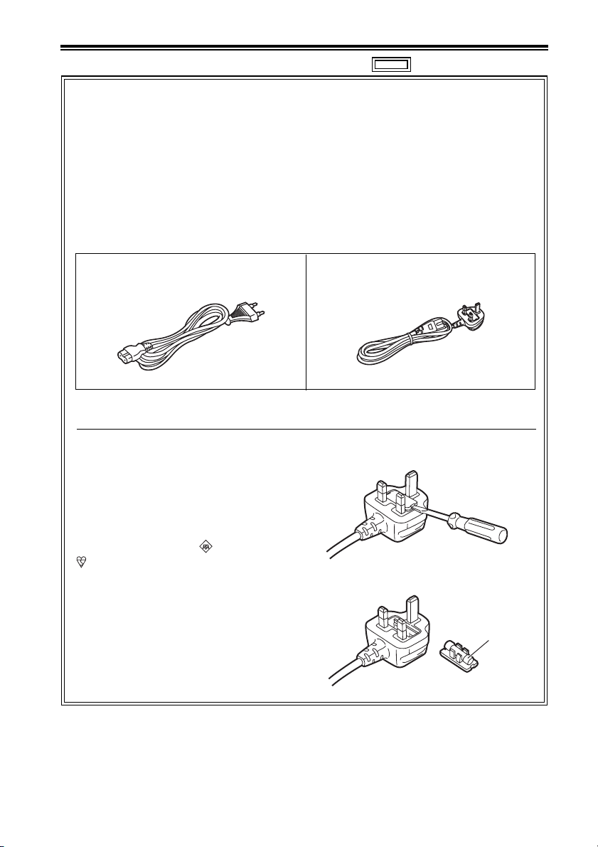
Caution for AC Mains Lead
For battery charger
FOR YOUR SAFETY PLEASE READ THE FOLLOWING TEXT CAREFULLY.
This product is equipped with 2 types of AC mains cable. One is for continental Europe, etc. and the
other one is only for U.K.
Appropriate mains cable must be used in each local area, since the other type of mains cable isnot
suitable.
FOR CONTINENTAL EUROPE, ETC.
Not to be used in the U.K.
FOR U.K. ONLY
This appliance is supplied with a moulded
three pin mains plug for your safety and
convenience.
A 5 amp fuse is fitted in this plug.
Should the fuse need to be replaced please
ensure that the replacement fuse has a rating
of 5 amps and that it is approved by ASTA or
BSI to BS1362.
Check for the ASTA mark or the BSI mark
on the body of the fuse.
If the plug contains a removable fuse cover
you must ensure that it is refitted when the
fuse is replaced.
If you lose the fuse cover the plug must not be
used until a replacement cover is obtained.
A replacement fuse cover can be purchased
from your local Panasonic Dealer.
FOR U.K. ONLY
How to replace the fuse
1. Open the fuse compartment with a screwdriver.
2. Replace the fuse
Fuse
7
Page 8
Read this first! (For AG-HPD24E) (continued)
indicates safety information.
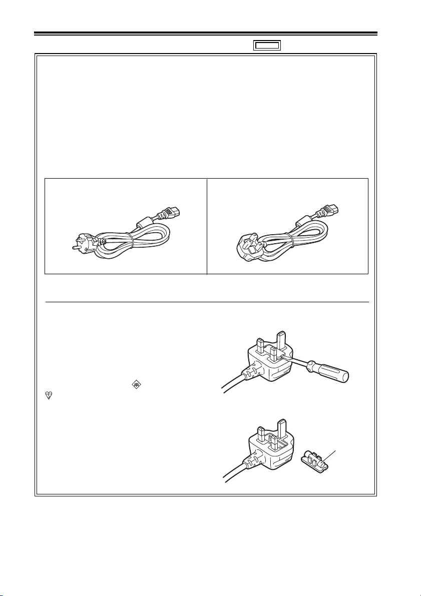
Caution for AC Mains Lead
For AC adaptor
FOR YOUR SAFETY PLEASE READ THE FOLLOWING TEXT CAREFULLY.
This product is equipped with 2 types of AC mains cable. One is for continental Europe, etc. and the
other one is only for U.K.
Appropriate mains cable must be used in each local area, since the other type of mains cable isnot
suitable.
FOR CONTINENTAL EUROPE, ETC.
Not to be used in the U.K.
FOR U.K. ONLY
This appliance is supplied with a moulded
three pin mains plug for your safety and
convenience.
A 13 amp fuse is fitted in this plug.
Should the fuse need to be replaced please
ensure that the replacement fuse has a rating
of 13 amps and that it is approved by ASTA or
BSI to BS1362.
Check for the ASTA mark or the BSI mark
on the body of the fuse.
If the plug contains a removable fuse cover
you must ensure that it is refitted when the
fuse is replaced.
If you lose the fuse cover the plug must not be
used until a replacement cover is obtained.
A replacement fuse cover can be purchased
from your local Panasonic Dealer.
FOR U.K. ONLY
How to replace the fuse
1. Open the fuse compartment with a screwdriver.
2. Replace the fuse
Fuse
8
Page 9

Read this first! (For AG-HPD24E) (continued)
EMC NOTICE FOR THE PURCHASER/USER OF THE APPARATUS
1. Applicable standards and operating environment (AJ-HPD24E)
The apparatus is compliant with:
• standards EN55103-1 and EN55103-2 2009, and
• electromagnetic environments E1, E2, E3 and E4
2. Pre-requisite conditions to achieving compliance with the above standards
<1> Peripheral equipment to be connected to the apparatus and special connecting
cables
• The purchaser/user is urged to use only equipment which has been recommended by
us as peripheral equipment to be connected to the apparatus.
• The purchaser/user is urged to use only the connecting cables described below.
<2> For the connecting cables, use shielded cables which suit the intended purpose of
the apparatus.
• Video signal connecting cables
Use double shielded coaxial cables, which are designed for 75-ohm type high-frequency
applications, for SDI (Serial Digital Interface).
Coaxial cables, which are designed for 75-ohm type high-frequency applications, are
recommended for analog video signals.
• Audio signal connecting cables
If your apparatus supports AES/EBU serial digital audio signals, use cables designed
for AES/EBU.
Use shielded cables, which provide quality performance for high-frequency
transmission applications, for analog audio signals.
• Other connecting cables (IEEE1394, USB)
Use shielded cables, which provide quality performance for high-frequency
applications, as connecting cables.
• When connecting to the DVI signal terminal, use a cable with a ferrite core.
• If your apparatus is supplied with ferrite core(s), they must be attached on cable(s)
following instructions in this manual.
3. Performance level
The performance level of the apparatus is equivalent to or better than the performance level
required by these standards.
However, the apparatus may be adversely affected by interference if it is being used in an EMC
environment, such as an area where strong electromagnetic fields are generated (by the
presence of signal transmission towers, cellular phones, etc.). In order to minimize the adverse
effects of the interference on the apparatus in cases like this, it is recommended that the
following steps be taken with the apparatus being affected and with its operating environment:
1. Place the apparatus at a distance from the source of the interference.
2. Change the direction of the apparatus.
3. Change the connection method used for the apparatus.
4. Connect the apparatus to another power outlet where the power is not shared by any
other appliances.
Pursuant to at the directive 2004/108/EC, article 9(2)
Panasonic Testing Centre
Panasonic Service Europe, a division of Panasonic Marketing Europe GmbH
Winsbergring 15, 22525 Hamburg, F.R. Germany
9
Page 10
Read this first! (For AG-HPD24P/AG-HPD24E)
■ About batteries that you can use with this unit
(Correct as of August 2011)
The battery that can be used with this unit is CGA-D54.
• The unit has a function for distinguishing batteries which can be used safety. The dedicated battery
(CGA-D54) supports this function. The only batteries suitable for use with this unit are genuine
Panasonic products and batteries manufactured by other companies and certified by Panasonic.
(Batteries which do not support this function cannot be used). Panasonic cannot in any way
guarantee the quality, performance or safety of batteries which have been manufactured by other
companies and are not genuine Panasonic products.
It has been found that counterfeit battery packs which look very similar to the genuine product are
made available to purchase in some markets. Some of these battery packs are not adequately
protected with internal protection to meet the requirements of appropriate safety standards. There
is a possibility that these battery packs may lead to fire or explosion. Please be advised that we
are not liable for any accident or failure occurring as a result of use of a counterfeit battery pack.
To ensure that safe products are used we would recommend that a genuine Panasonic battery
pack is used.
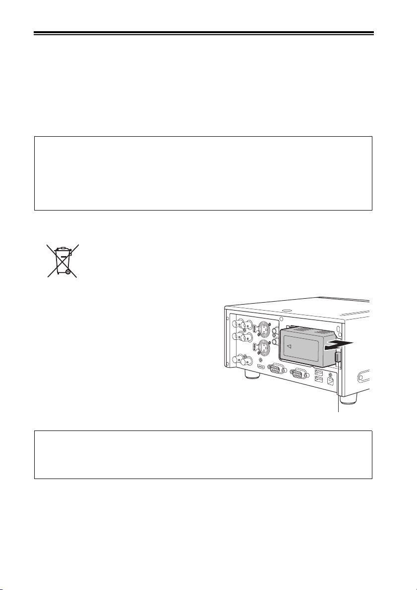
EU
To remove the battery
Main Power Battery
Press the battery release button.
Back-up Battery
• For the removal of the battery for disposal at the
end of its service life, please consult your dealer.
3D image viewing
• When viewing 3D images, observe the viewing precautions indicated in the operating
instructions of the monitor. If you continue viewing 3D images in incorrect conditions, it may
cause eyestrain or other adverse effects.
10
Battery release button
Page 11

• The SDHC logo is a trademark of SD-3C, LLC.
• HDMI, the HDMI logo and High-Definition Multimedia Interface are trademarks or registered
trademarks of HDMI Licensing LLC of the United States and/or other countries.
•Microsoft
United States and/or other countries.
• Apple and Macintosh are registered trademarks of Apple Inc. of the United States and other
countries.
• Microsoft product screen shots reprinted with permission from Microsoft Corporation.
• Names of products, brands, etc., appearing in this manual are trademarks or registered trademarks
of their respective owners.
Illustrations in this manual
• Note that illustrations of the unit and menu screens may differ from those you actually see.
Note concerning screenshots in these instructions
• Screenshots from the AG-HPD24P are used in these operating instructions.
Page references
• In this manual, references to pages are indicated as: (➝ page 00).
Terminology
• The term “SD memory card” is used below as a generic term for both SD and SDHC memory cards.
• A memory card with the “P2” logo (for example the separately sold AJ-P2E064XG) is referred to as a
“P2 card.”
• A recordable media device such as an external hard disk drive connected to a USB port is referred
to as a “storage device.”
• A single continuous video recording is referred to as a “clip.”
• Orange button labels indicate alternate functions enabled by holding the SHIFT button. The operating
instructions refer to the buttons only by label, without mentioning the SHIFT button.
®
and Windows® are registered trademarks or trademarks of Microsoft Corporation® of the
Website URL
• URL:http://pro-av.panasonic.net/
About copyrights
• Copyright laws may prohibit use, except for personal pleasure, of your recorded video and audio
content without permission of the rights holder.
11
Page 12

Contents
Volume 1
Read this first! (For AG-HPD24P) ........ 2
Read this first! (For AG-HPD24E) ........ 6
Read this first! (For AG-HPD24P/
AG-HPD24E) ...................................... 10
Turning Power On and Off .................. 27
Turning On ............................................ 27
Turning Off ............................................ 27
About Auto Power Off during operation
Setting the Year, Month, Day and
Time ...................................................28
... 28
Usage Precautions............................... 14
Regarding this unit .......................... 14
AC adaptor ........................................... 15
Battery .................................................. 15
Battery characteristics .......................... 15
Remove the battery after use. ............... 16
Before Use ........................................... 16
Always confirm the year, month, day, time and
time zone, and set as necessary
Compatible storage media .................... 16
.......... 16
Supplied Accessories, Optional
Accessories........................................ 17
Supplied Accessories ..................... 17
Optional Accessories .......................... 17
Control Reference Guide..................... 18
Controls ............................................ 18
Slots, etc. ............................................. 21
I/O Connectors ..................................... 22
Preparation ........................................... 24
Charging the battery ....................... 24
Power Preparations ............................. 25
Using a battery ................................. 25
Installation ............................................. 25
Removal ................................................ 25
Using the AC adaptor .......................... 26
Installation ............................................. 26
Removal ................................................ 26
Basic Operation....................................29
About P2 Cards ................................29
Inserting a P2 Card ............................... 29
P2 Card Access Lamp and P2 Card
Status .................................................. 29
About P2 Card Recording Times .......... 30
Removing P2 Cards .............................. 31
Preventing Accidental Deletion ............. 31
Menu Operations ..................................32
LCD Monitor Settings ..........................33
Thumbnail Screen Display ..................34
Displaying the Thumbnail Screen ......... 34
Recording .............................................35
Playback ...............................................35
Playback from the Record/Playback
Screen (Thumbnail Screen Off) .......... 35
Playback from the Thumbnail Screen ... 35
Time Code, User Bits and CTL ...........36
Time Code ............................................. 36
User Bits ................................................ 36
CTL ........................................................ 36
External Connections .......................... 37
USB Device .......................................37
USB HOST ............................................37
3D Signal Recording and Playback ....38
Connections .........................................39
Recording Connection Example ........... 39
Playback Connection Example ............. 40
12
Page 13

Contents
Selecting the 3D REC/PB Mode .......... 42
Turning Power On and Off .................. 43
Turning On ............................................ 43
Turning Off ............................................ 43
Recording and Playback ..................... 44
Recording ............................................. 44
Playback ............................................... 45
Displaying 3D Thumbnails .................. 46
Displaying the Thumbnail Screen ......... 46
Thumbnail Screen Names and
Functions ............................................ 46
Synchronous Playback ........................48
Connections ......................................... 48
Selecting SYNC PB Mode ................... 48
Playback ............................................... 49
Correctly Synchronizing Playback ........ 49
Playback from the Playback Screen
(Thumbnail Screen Off) ...................... 50
Playback from the Thumbnail Screen ... 51
Setup Menu ...........................................52
Specifications .......................................53
Index ......................................................58
Volume 2
Available Modes
Main Mode
USB Device Mode
3D Recording/Playback Mode (3D REC/
PB)
Synchronous Playback Mode (SYNC PB)
Screen Display
Time Code, User Bits, CTL
Setup Menu
Using a Keyboard
For Long and Trouble-Free Operation
Index
13
Page 14

Usage Precautions
Regarding this unit
■ Panasonic makes no guarantees for
your recordings
• Please understand that Panasonic makes no
guarantees for your recordings in cases where
video and/or audio were not recorded as you
intended due to problems with this unit, P2
cards, or SD memory cards.
■ Be careful to avoid getting water
inside the unit when using it in rainy
or snowy weather, or near the sea
shore.
• The unit or card may be damaged. (In some
cases, it may become unrepairable.)
■ Do not install this unit in a location
exposed to direct sunlight
• This may deform the cabinet or damage the
LCD screen.
■ Keep the unit away from
elecromagnetic devices (such as TVs
and video game machines).
• Using the unit on or near a TV may result in
distorted video or audio due to
electromagnetic radiation.
• The strong magnetic field produced by
loudspeakers and large monitors can damage
recordings or distort video images.
• Electromagnetic radiation from computers can
distort video and audio.
• If a malfunction is suspected to have occurred
due to the influence of a magnetic device, turn
the unit off and remove the battery or unplug
the AC adaptor. Then re-install the battery or
reconnect the AC adaptor. Finally, turn the unit
back on.
■ Do not use the unit near a radio
transmitter or high-voltage
equipment.
• Recorded video and audio may be disrupted if
used near a radio transmitter or high-voltage
equipment.
■ When using the unit at the sea shore,
be careful to avoid allowing sand or
dust to get inside.
• Sand and dust can damage the unit or card.
(Be especially careful when inserting and
removing cards.)
■ When carrying the unit, be careful not
to drop it.
• The unit can be damaged by strong shocks,
and may malfunction.
■ Keep the unit away from contact with
insecticides or other volatile
materials.
• Insecticides and other volatile materials can
deform the unit and dissolve the finish.
• Do not leave the unit in contact with rubber or
vinyl products for long periods.
■ Secure deletion of data from memory
cards and storage devices prior to
disposal or transfer of the unit.
• The format and delete functions on this unit or
a PC will only change the file management data
and leave data on the memory card or storage
device intact. It is recommended that cards or
storage devices either be physically destroyed
or that commercially sold software be used to
completely delete any data they contain.
Management of data on memory cards and
storage devices is the sole responsibility of the
user.
■ Liquid crystal displays
• The pixels of the LCD monitor are controlled to
obtain high precision with 99.99 % of the
effective pixels. This leaves less than 0.01 % of
pixels that may not light or may remain on all
the time. These phenomena are normal and will
have no effect on the images you shoot.
• There may be some unevenness on the screen
depending on the image displayed.
• Wiping or rubbing the LCD screen with a rough
cloth may damage it.
Usage Precautions: Regarding this unit
14
Page 15

• A temporary afterimage (burn-in) may occur
when the same image or text is displayed for a
long time, although it can be recovered by
turning power off for several hours.
• LCD response and brightness vary with
operating temperature.
■ Information on software for this product
1. Included with this product is software licensed under the GNU General Public License (GPL) and
GNU Lesser General Public License (LGPL), and users are hereby informed that they have the right
to obtain, change and redistribute the source codes of this software.
Details on GPL and LGPL can be found on the installation CD provided with the unit. Refer to the
folder called “LDOC”.
(Details are given in the original (English-language) text.)
See our website (➝ “Website URL” page 11) to obtain the source code.
The manufacturer asks users to refrain from directing inquiries concerning the source codes they
have obtained and other details to its representatives.
2. Included with this product is software which is licensed under MIT-License.
This information is provided in the LDOC folder (in the original English language text) on the install CD-
ROM supplied with the unit.
• In a high-temperature and high-humidity
location, the LCD panel characteristics may
change and result in uneven image quality.
AC adaptor
Usage Precautions
Use the supplied AC adaptor. Read the Operating Instructions (➝ “Using the AC adaptor” page 26)
before use.
Battery
Use the supplied battery. (CGA-D54 for the AG-HPD24P / CGA-D54s for the AG-HPD24E)
Battery characteristics
This unit uses a rechargeable lithiumion battery that uses its internal chemical reaction to generate
electrical energy. This reaction is easily influenced by the ambient temperature and humidity, and the
battery’s effective operating time is reduced as the temperature rises or falls. In very low temperatures,
the battery may last only 5 minutes.
Protective circuitry functions if you use the battery where it is very hot and you will have to wait before
you can use it again.
Usage Precautions: AC adaptor
15
Page 16

Remove the battery after use.
Completely remove the battery. (The battery continues to be used even if you have turned the unit off.)
The battery can over discharge if you leave it in the unit and it may become impossible to recharge it.
Before Use
Always confirm the year, month, day, time and time zone, and set as necessary
The clock setting affects management of recorded content and playback control. Before recording,
confirm the correct year, month, day, time and time zone settings. (➝ “Setting the Year, Month, Day and
Time” page 28)
Compatible storage media
The following types of storage media can be used. See the specified pages for details.
•P2 Card (➝ “Handling P2 Card Recording” Vol. 2, page 91)
• SD/SDHC Memory Cards* (➝ “Use of SD/SDHC Memory Cards” Vol. 2, page 92)
* SD/SDHC memory cards cannot be used with this unit for video/audio recording and playback.
Usage Precautions: Before Use
16
Page 17
Supplied Accessories, Optional Accessories
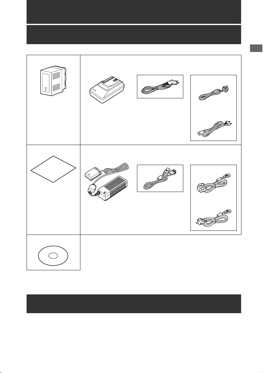
Supplied Accessories
Battery
For part numbers for
the battery, see
“Optional Accessories”
below.
3D connection label AC adaptor / AC power supply cables
Battery charger / AC power supply cables
AG-HPD24P AG-HPD24E
AG-HPD24P AG-HPD24E
Supplied Accessories, Optional Accessories
(For the U.K.)
(For areas other
than the U.K.)
(For the U.K.)
(For areas other
than the U.K.)
CD-ROM
• After unpacking, dispose of the AC power supply cable caps and packing materials properly.
Optional Accessories
• Battery
CGA-D54 (7.2 V, 5400 mAh: equivalent to accessory battery for the AG-HPD24P)
CGA-D54s (7.2 V, 5400 mAh: equivalent to accessory battery for the AG-HPD24E)
Supplied Accessories, Optional Accessories: Supplied Accessories
17
Page 18
Control Reference Guide
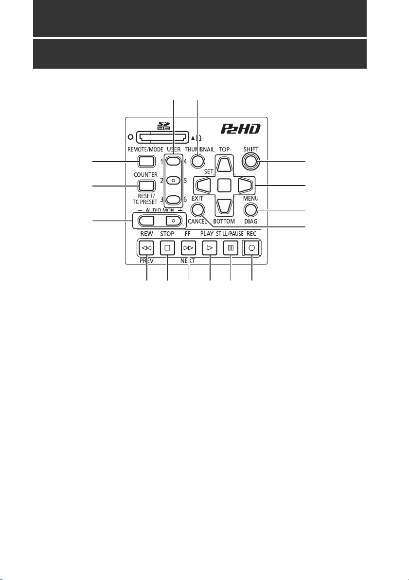
Controls
5
4
1 6
2
7
8
3
9
10 11 12 14 1513
About button labels:Orange labels indicate alternate functions enabled by simultaneously pressing
SHIFT.
<Example> Press the SHIFT and REMOTE/MODE buttons at the same time to execute the MODE
button function.
1. REMOTE/MODE button
REMOTE button:
Enables remote control of the unit via the
REMOTE connector.
MODE button:
Selects the USB device mode (USB DEVICE),
3D recording/playback mode (3D REC/PB),
or synchronous playback mode (SYNC PB).
USB DEVICE
Enables access to the P2 card in the P2
card slot of this unit as a mass storage
device on a personal computer
connected via USB 2.0.
3D REC/PB
Synchronizes the operation of two units to
record and playback Dual P2 3D clips
(page 38).
SYNC PB
Synchronizes the operation of two units to
play back 3D clips (page 48) on P2 cards
that were recorded using machines that
do not have native support for Dual P2 3D.
2. COUNTER, RESET/TC PRESET button
COUNTER button:
Selects the type of data for the counter
display, in the following sequence.
(➝ “Time Code, User Bits, CTL” Vol. 2, page 47)
Control Reference Guide: Controls
18
Page 19

RESET/TC PRESET button:
Resets the CTL counter when displayed.
When the counter displays TC or UB, presets
the time code/user bits.
3. AUDIO MON button
Monitor audio volume adjustment:
Press either the + or –, AUDIO MON button to
display the loudspeaker/headphone audio
volume level, and hold the button to adjust.
Wait a short time or press SET or EXIT to
return the display to normal.
Recording audio volume adjustment:
(➝ “Recording Clips” Vol. 2, page 6)
4. USER1-3, 4-6buttons
Users can assign any functions to these
buttons.
(➝ “Setup Menu” Vol. 2, page 50)
5. THUMBNAIL button
Selects whether to show or hide the
thumbnail screen.
(➝ “Thumbnail Screen Display” page 34)
6. SHIFT button
Hold this button while pressing another
button to perform the alternate function of that
button.
Functions of the SHIFT button that are not
indicated by orange button labels:
To select the group of clips from immediately
before the select clip to the clip at the current
cursor position
SHIFT + SET buttons
(➝ “Selecting and Deselecting Clips” Vol. 2,
page 16)
Combine display of selected storage device
partition/folder thumbnails
SHIFT + SET buttons
(➝ “Operations in the EXPLORE screen”
Vol. 2, page 32)
Moving storage device partitions/folders
SHIFT + +/– buttons
(➝ “Displaying thumbnails of clips on storage
devices and viewing video on the monitor”
Vol. 2, page 33)
7. Cursor control buttons
Up/Down/Left/Right cursor buttons:
• Controls cursor movement for thumbnails
and menus.
• During playback, press the Left/Right
cursor buttons to activate SHTL mode to
change playback speed.
(➝ “Playing Back at Variable Speed” Vol. 2,
page 43)
• Press the SET button to pause variable
speed playback.
• While paused, press the Up/Down cursor
buttons to step one frame forward or back.
(➝ “Frame-by-frame playback” Vol. 2, page 8)
• These buttons also adjust recording audio
volume.
(➝ “Recording Clips” Vol. 2, page 6)
TOP/BOTTOM buttons:
Move the cursor to the first (TOP) or last
(BOTTOM) thumbnail.
SET button:
Selects thumbnails or menu items.
◆ NOTE:
• No selection occurs if SET is held too long.
8. MENU, DIAG button
MENU button:
This button displays the menu.
DIAG button:
When the menu is not displayed, pressing
this button displays a diagnostics screen
showing various conditions.
(➝ “Deck Information (DIAG) Icons” Vol. 2, page
45)
9. EXIT, CANCEL button
EXIT button:
Closes the menu, or returns from the storage
explorer to normal display.
Control Reference Guide
Control Reference Guide: Controls
19
Page 20

CANCEL button:
This button cancels a selection or interrupts
copying.
10.REW, PREV button
REW button:
Fast rewind during playback. Speed is
selectable from the menu setting SETUP -
BASIC - FF.REW MAX.
PREV button:
During playback, cues the previous clip or
clip and text note location.
In 3D REC/PB and SYNC PB modes, cues a
clip when paused.
◆ NOTE:
• Cueing during playback is not available in
3D REC/PB mode.
• Cueing is only available when paused in
SYNC PB mode.
11.STOP button
Stops playback or recording.
12.FF, NEXT button
FF button:
Executes fast forward during playback.
Speed is selectable by the menu setting
SETUP - BASIC - FF.REW MAX.
NEXT button:
During playback, cues the next clip or clip
and text note location.
In 3D REC/PB and SYNC PB modes, cues a
clip when paused.
14.STILL/PAUSE button
Press during playback to pause (STILL) and
display a still image.
Press during recording to toggle recording
standby (PAUSE).
Press to resume recording from standby.
15.REC button
During playback, press this button to check
video and audio in EE mode on the recording/
playback screen (with the thumbnail screen
disabled). Except when stopped, pressing
this button activates EE mode, which remains
active until you press another button. EE
mode monitoring is only available when the
playback video format matches the SETUP -
SYSTEM - FORMAT menu setting.
Press this button and the PLAY button
simultaneously to start recording.
Press this button and the STILL/PAUSE
button simultaneously to activate recording
standby. Remote camera recording can be
enabled from the menu. The SETUP - BASIC
- AUTO REC menu setting enables remote
recording.
(➝ “Setup Menu” Vol. 2, page 50)
◆ NOTE:
• Cueing during playback is not available in
3D REC/PB mode.
• Cueing is only available when paused in
SYNC PB mode.
13.PLAY button
Activates playback.
(➝ “Playback” page 45, ➝ “Playing Back Clips”
Vol. 2, page 43)
Control Reference Guide: Controls
20
Page 21
Slots, etc.
6 7 8 9
Control Reference Guide
1
2
3
4
5
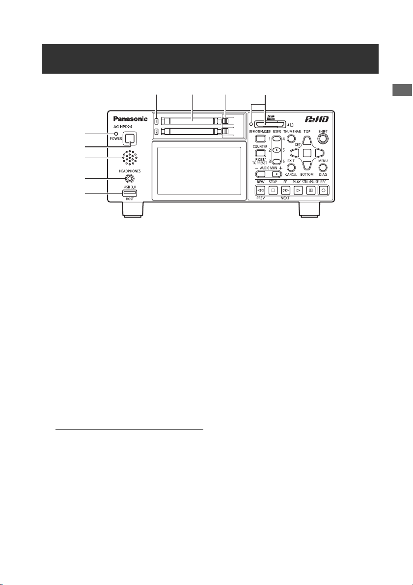
1. POWER lamp
(➝ “Turning Power On and Off” page 27)
2. POWER button
Press and hold to turn power on and off.
(➝ “Turning Power On and Off” page 27)
3. Speaker
Outputs monitored audio. Speaker output is
disabled when headphones are connected.
4. Headphone jack
Headphones can be plugged in here.
Outputs monitored audio when headphones
are connected.
5. USB HOST port (USB 3.0 Type A)
(➝ “USB HOST” page 37)
◆ NOTE:
• Use double-shielded cable to connect to
this port.
• Use a USB 3.0 compliant cable to connect
USB 3.0 compatible storage devices.
6. P2 card access lamps
(➝ “P2 Card Access Lamp and P2 Card Status”
page 29)
7. P2 card slots
(➝ “Inserting a P2 Card” page 29)
8. EJECT buttons
(➝ “Inserting a P2 Card” page 29)
9. SD/SDHC memory card slot and access lamp
Insert an SD/SDHC memory card.
Insert the card cut-corner-edge first and
label-side up, until it latches into place.
To remove it, ensure that the green lamp is
off, then release the latch by gently pushing
the card in again.
See the following for details.
(➝ “Use of SD/SDHC Memory Cards” Vol. 2,
page 92)
Control Reference Guide: Slots, etc.
21
Page 22

I/O Connectors
1
4
5
6
7 8 9 1110
1. TIME CODE IN/OUT Jacks
TIME
CODE IN:
TIME
CODE
OUT:
Accepts an external time code
for recording onto P2 cards.
Outputs the playback time
code during playback.
Outputs the time code from the
internal time code generator
during recording.
2. ANALOG AUDIO IN jacks
These accept analog audio input.
3. ANALOG AUDIO MON output jacks
The audio signal (CH1 to CH8) selected from
the SETUP - AUDIO - MONITOR CH menu
setting (➝ “Setup Menu” Vol. 2, page 50) is
output here.
4. REF IN jack
Input connectors for HD and SD reference
video signals.
Connect to the VIDEO OUT jack of the slave
device when using 3D REC/PB and SYNC PB
modes.
(➝ “3D Signal Recording and Playback”
2
3
14
13
12
page 38, ➝ “Synchronous Playback” page
)
48
◆ NOTE:
• The HD reference video signals must be
positive and negative polarity tri-level sync
signals. These signals must match the
format of the input signal and SYSTEM
data format.
• The HD reference is only usable with menu
settings SETUP - SYSTEM - FREQUENCY
23.98 Hz, 24 Hz, 59-23, or 60-24.
• SD reference video must include a black
burst signal that complies with SMPTE
170M and ITU 624-4.
• In both 3D REC/PB and SYNC PB modes,
when the menu setting SETUP - SYSTEM -
FREQUENCY is 59.94 or 50 Hz, only a
black burst reference signal can be used.
When the setting is 23.98 or 24 Hz, only the
HD reference can be used.
• Video and audio output signals may be
degraded when no reference video signal
is provided. We recommend using this unit
in systems that provide a reference video
signal for input.
Control Reference Guide: I/O Connectors
22
Page 23

• When recording 720p with an HD
reference or no reference input, the
recorded phase may be shifted from the
input signal.
• When the SETUP - SYSTEM - FREQUENCY
menu setting is 59-23 or 60-24, the HD
reference signal can only synchronize
playback.
5. VIDEO OUT jack
Provides analog composite video signal
output.
No signal is output when the SETUP -
SYSTEM - FREQUENCY menu setting is
24 Hz or 60-24.
In both 3D REC/PB and SYNC PB modes, the
sync signal output here is exclusively for use
by another AG-HPD24.
➝ “3D Signal Recording and Playback”
(
page 38,
48)
➝ “Synchronous Playback” page
6. HD/SD-SDI IN/OUT jacks
These provide input and output of serial
digital component audio/video signals.
control the unit.
◆ NOTE:
• Use double-shielded cable for
connections.
9. LINK(D) connector
Use this connector to link two units for 3D
REC/PB and SYNC PB modes.
(
➝ “3D Signal Recording and Playback”
page 38,
48)
◆ NOTE:
• Use a double-shielded RS-422A cable not
➝ “Synchronous Playback” page
longer than 1 m long for connection.
10.KEYBOARD port (USB 2.0 Type A)
Connect an external USB keyboard to enter
meta data.
(➝ “Using a Keyboard” Vol. 2, page 80)
11.LINK(M) port (USB 2.0 Type A)
➝ “3D Signal Recording and Playback”
(
page 38,
48)
➝ “Synchronous Playback” page
Control Reference Guide
◆ NOTE:
• Use 5C-FB or equivalent double-shielded
cable for connections.
7. HDMI OUT port
Connects to a monitor or TV using an HDMI
cable. In 3D REC/PB and SYNC PB modes,
3D video can be displayed by connecting a
3D monitor.
(➝ “3D Signal Recording and Playback”
, ➝ “Synchronous Playback” page
page 38
)
48
◆ NOTE:
• This machine does not support VIERA link.
Connecting it to a VIERA link compatible
device with an HDMI cable may cause
VIERA link to malfunction on that device.
8. REMOTE connector
Connect to an external controller to remotely
◆ NOTE:
• Use double-shielded cable for
connections.
12.USB2.0 device/LINK(S) port (Type B)
(
➝ “USB Device” page 37, ➝ “3D Signal
Recording and Playback” page 38,
“Synchronous Playback” page 48)
◆ NOTE:
• Use double-shielded cable for
connections.
➝
13.Battery latch release button
(➝ “Using a battery” page 25)
14.Power supply/battery mounting location
(➝ “Power Preparations” page 25)
Control Reference Guide: I/O Connectors
23
Page 24
Preparation
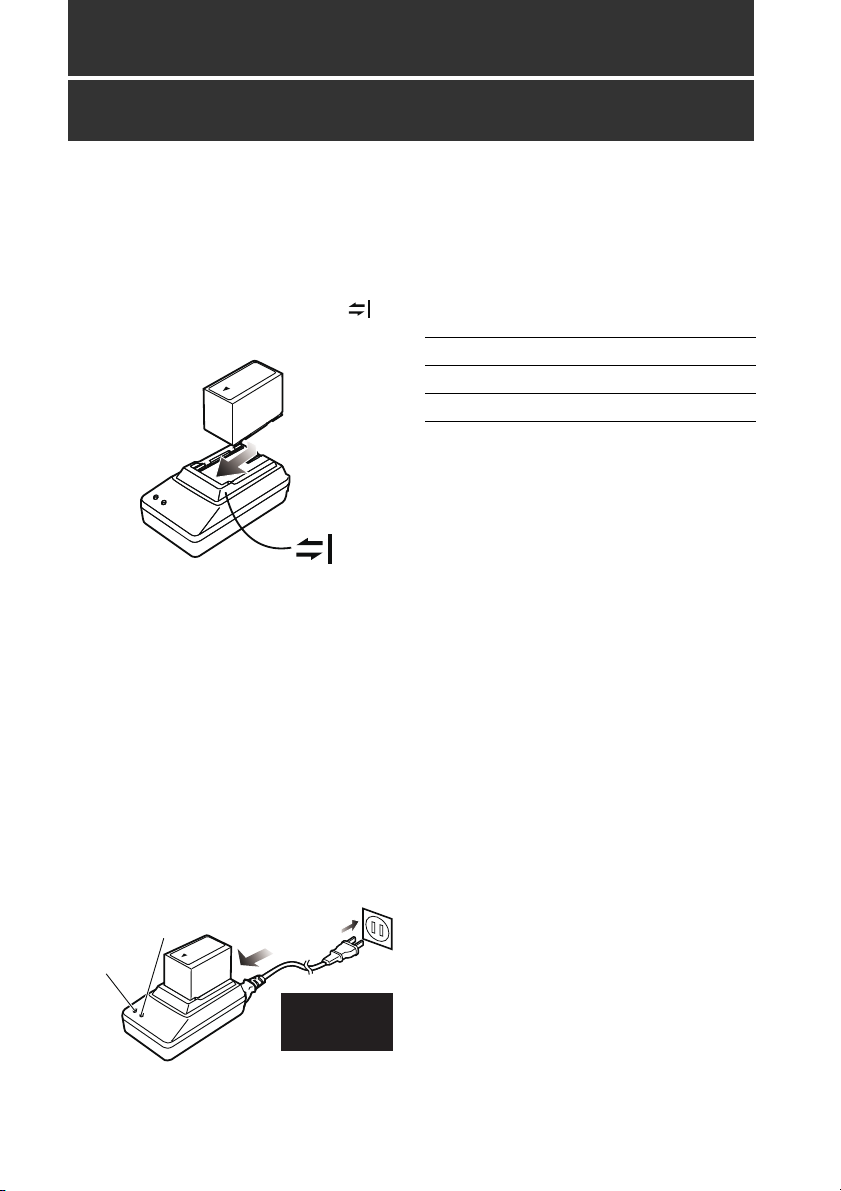
Charging the battery
The battery is not charged when the product is
purchased. Use the steps below to fully charge
the battery using the supplied charger. We
recommend keeping one spare battery on hand.
1 Place the battery level on the charger and
slide it in the direction of the arrows on
the charger.
2 Plug the battery charger’s AC power
supply cable into the charger, and then into
a power outlet.
Connect the AC power supply cable in A-B
order.
• The POWER lamp and CHARGE
lamp on the charger light indicating
that charging has started.
• If the CHARGE lamp does not light
when the battery is installed,
reinstall the battery correctly.
B
Insert the
plugs all the
way in.
POWER
CHARGE
A
• The CHARGE lamp on the charger
goes out when charging ends.
3 Slide the battery off the charger.
■ Charging time and battery life
estimates for the supplied battery
Capacity 5400 mAh
Charging time Approx. 330 min.
Continuous playback time Approx. 160 min.
• The above times are estimates for playing back
continuously recorded clips in AVC-Intra 100 to
an E-series P2 card.
• The above values apply at ambient 20 °C
(68 °F) and 60 % relative humidity. Charging
time may be longer under other conditions.
• The battery becomes hot during usage and
charging.
• When the battery temperature becomes
excessively high or low, or it has become
discharged after a long period of inactivity, the
CHARGE lamp may flash two or three times
before automatic charging starts.
• If the CHARGE lamp continues flashing when
the battery is at normal temperature, it may be
defective and you should contact your
supplier.
• Charging time becomes longer for a hot
battery.
• Using the charger or AC adaptor near a radio
may interfere with radio reception. Place the
charger or AC adaptor at least 1 meter away
from a radio.
• The charger may emit noise during charging.
This is not a malfunction.
• No guarantees are given for the operation of
the CGR-D16/CGR-D16s (1600 mAh) battery
pack.
Preparation: Charging the battery
24
Page 25
Power Preparations
Installation
Using a battery
1 Slide in the battery until it clicks into place.
Removal
1
POWER lamp
Power Preparations Power Preparations
1 Hold the POWER button for two seconds to
turn the power off, and confirm that the
POWER lamp is off.
2 Press the battery lock release button to
slide out the battery.
Hold the battery to prevent it from falling out.
◆ NOTE:
• Always be sure that the unit is turned off
before removing the battery.
Battery latch release button
Power Preparations: Using a battery
25
Page 26
Using the AC adaptor
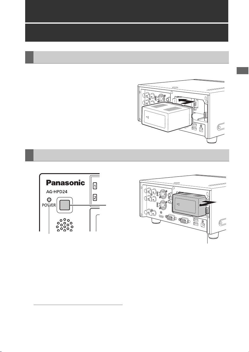
Installation
1 Plug the AC adaptor’s AC power supply
cable into the adaptor, and then into a
power outlet.
Connect the AC power supply cable in A-B
order.
2 Slide in the DC power supply cable plate
until it clicks into place.
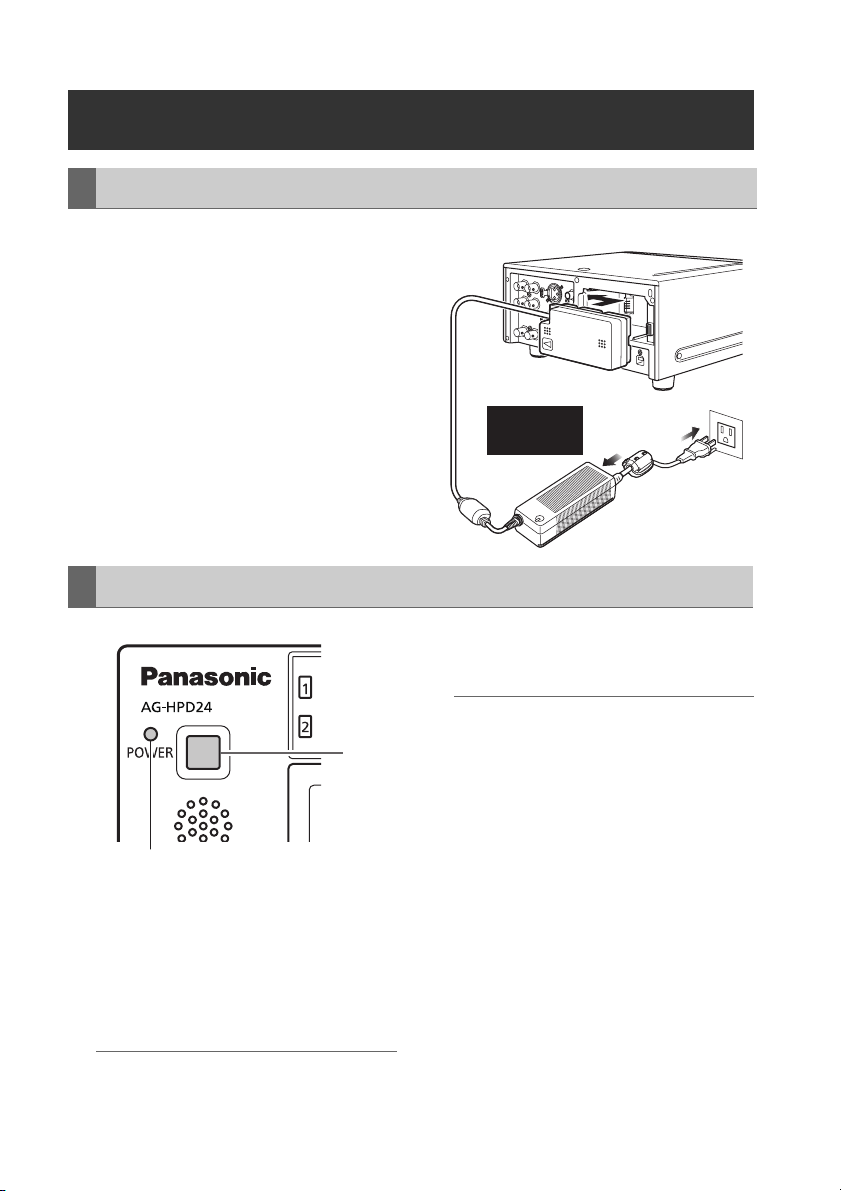
Removal
Insert the
plugs all the
way in.
A
B
3 Unplug the adaptor’s AC power supply
cable from the wall outlet.
POWER lamp
1 Hold the POWER button for two seconds to
turn the power off, and confirm that the
POWER lamp is off.
2 Press the battery lock release button and
slide out the DC power supply cable plate.
◆ NOTE:
• Always be sure that the unit is turned off before
removing the DC cord connector plate.
Power Preparations: Using the AC adaptor
26
◆ NOTE:
• The AC Adaptor is designed to operate on
1
world-wide mains voltages (100 to 240 V)
and frequencies (50/60 Hz). However,
power outlet configurations differ in
different countries. Use a plug that is
designed for the country of operation. If
necessary, contact your supplier to obtain
the appropriate plug adaptor.
• When not using the unit, unplug the
adaptor’s AC power supply cable from the
wall outlet.
• The power lamp on the AC adaptor
normally remains lit for a while after it is
unplugged from the wall outlet.
Page 27
Turning Power On and Off
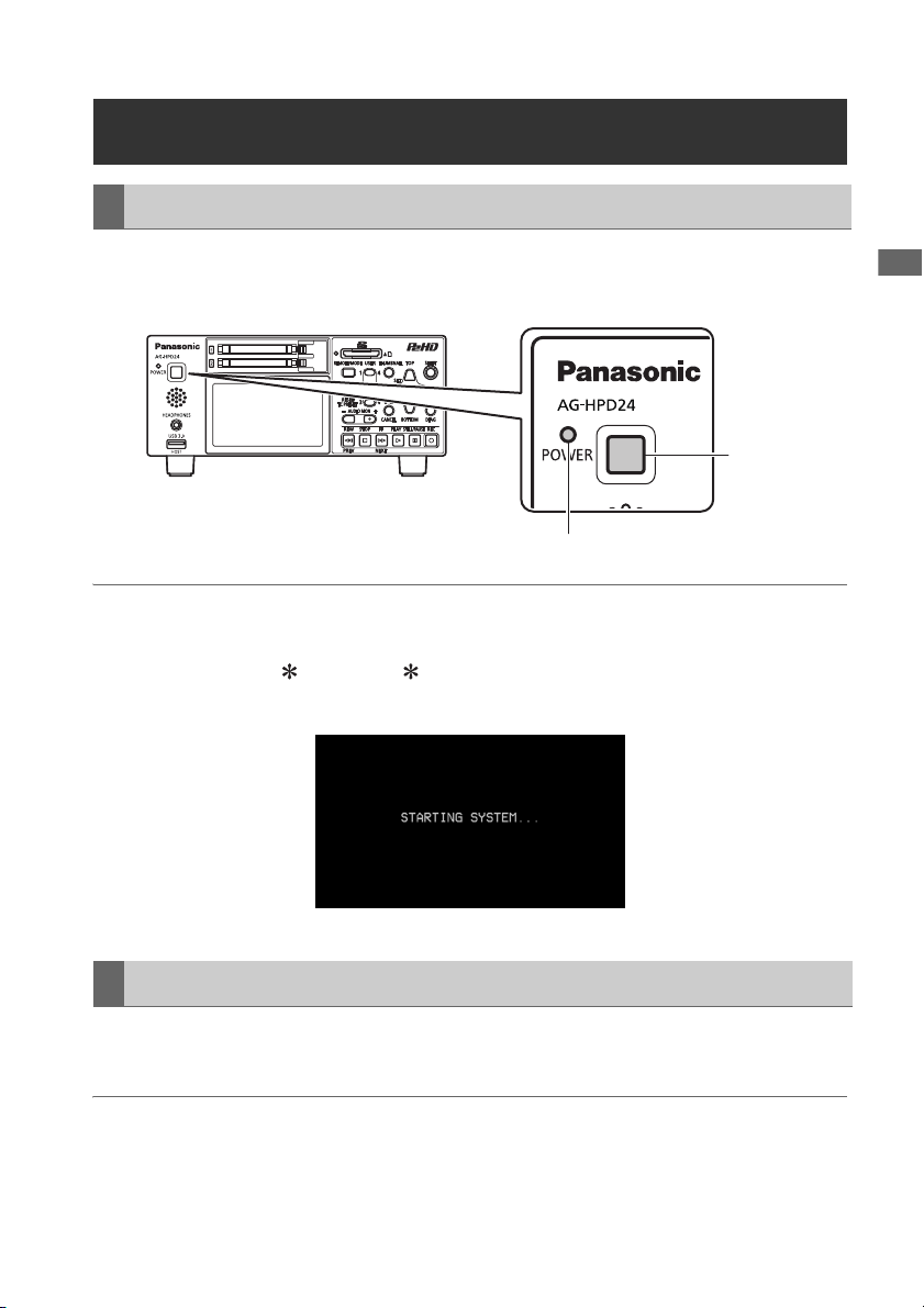
Turning On
From the power-off state, hold the POWER button for one second to turn the unit on.
When on, the POWER lamp lights green.
POWER
button
POWER lamp
◆ NOTE:
The following messages appear during startup.
• “STARTING SYSTEM...”: blinks during startup.
• “AUTO POWER OFF = min”: where “ ” is the time configured under the menu setting SETUP -
SYSTEM - AUTO POWER OFF. When the menu setting is OFF, AUTO POWER OFF is not displayed.
Power Preparations Power Preparations
Turning Off
From the power-on state, hold the POWER button for two seconds to turn the unit off.
The POWER lamp blinks during shutdown processing, until the unit turns off.
◆ NOTE:
• When a battery fault occurs, turn the power off and replace with a charged battery or switch to the AC
adaptor before turning power back on.
Power Preparations: Turning Power On and Off
27
Page 28

About Auto Power Off during operation
The Auto Power Off function automatically turns the unit off after a short period if no operation such as
recording, playback, copying or formatting is performed during that time. To resume operation after Auto
Power Off, press the POWER button again.
◆ NOTE:
• The Auto Power Off time can be changed by the SETUP - SYSTEM - AUTO POWER OFF menu setting
(➝ “Setup Menu” Vol. 2, page 50).
Setting the Year, Month, Day and Time
Set the clock before using the unit the first time.
1 Hold the POWER button for one second to
turn the unit on.
2 Press the MENU button to open the menu.
(➝ “Menu Operations” page 32)
3 Use the Up/Down/Left/Right cursor buttons
to select the SETUP - SYSTEM - CLOCK
SET menu item, and press the SET button.
The clock setting screen is displayed. The
default values are the current time settings.
4 Use the Left/Right cursor buttons to select
the digits to be set.
• The AG-HPD24P clock is displayed
in hour:minute, month/day/year, and
time zone sequence.
(The AG-HPD24E clock is displayed
in hour:minute, day/month/year, and
time zone sequence.)
• In time zone, set the difference in
hours from Greenwich Mean Time.
• Hours are displayed in 24-hour
format.
5 Press the Up/Down cursor buttons to set
the year, month, day, time and time zone.
6 Set the calendar and press the SET button.
Pressing the SET button sets the clock to the
set time.
◆ NOTE:
• Since the clock is affected by deviation, it
should be checked before use.
• If you require an exact time setting, check
and reset the time before use.
• The date format on the setting screen can
be changed by the SETUP - THUMBNAIL -
DATE FORMAT menu selection.
• During 3D REC/PB and SYNC PB modes,
the slave unit temporarily synchronizes with
the clock setting on the master unit, and
returns to its original setting upon exiting
these modes.
Power Preparations: Setting the Year, Month, Day and Time
28
Page 29
Basic Operation
About P2 Cards
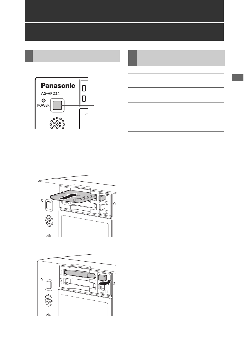
Inserting a P2 Card
ヒ
ビ
1
1 Hold the POWER button for one second to
turn the unit on.
2 Insert a P2 card into a P2 card slot until the
EJECT button pops out.
3 Fold the EJECT button toward the right.
P2 Card Access Lamp and P2 Card Status
P2 Card
Access Lamp
Lights green Writing and reading are
Lights orange Writing and reading are
Flashing
orange
Fast flashing
orange
Flashing green No available space on the P2
P2 Card Status
enabled.
enabled for the current
recording (including LOOP
REC).
Writing or reading is in
progress.
Currently accessing P2 card
using USB device mode.
NOTE:
• Do not turn the unit off or
eject the P2 card when the
lamp is flashing orange,
such as while recording.
P2 card being recognized.
card. Only reading is
possible.
The P2 card contains the
maximum number of clips.
Only reading is possible.
The write-protect switch on
the P2 card is set to
PROTECT. Only reading is
possible.
Basic Operation
Basic Operation: About P2 Cards
29
Page 30

Extinguished The P2 card is not formatted
properly. Reformat it in this
unit.
The card is incompatible with
this unit. Replace the card.
The P2 card is not inserted.
The P2 card is not accessible
using USB device mode.
About P2 Card Recording Times
• 32 GB, 16 GB and 8 GB P2 cards have
recording times of 1/2, 1/4 and 1/8th of that
provided by a 64 GB P2 card, respectively.
• 3D recording and playback times may be
shorter than those listed above.
■ About P2 cards and SD/SDHC memory
cards
Visit the P2 support desk page at the website
below for the latest information on P2 cards and
SD/SDHC memory cards. (➝ “Website URL”
page 11)
P2 card recording times
■ Recording time on a single 64 GB card
HD Mode
Video format
1080-59.94/
1
50i*
1080-24PN
(Native)
720-59.94P/
1
50P*
720-24PN
(Native)
*1: Includes recording of DVCPRO HD with pull-
down at 30P, 24P and 25P.
SD Mode
Video format
480-59.94i/
576-50i*
Recording format and time
DVCPRO HDAVC-
Intra 100
Approx.
64 min.
Approx.
64 min.
---- Approx.
80 min.
Approx.
64 min.
Approx.
160 min.
Approx.
64 min.
Approx.
160 min.
Recording format and time
DVCPRO 50DVCPRO*2DV*
3
Approx.
128 min.
Approx.
256 min.
AVC-
Intra 50
Approx.
128 min.
Approx.
160 min.
Approx.
128 min.
Approx.
320 min.
2
Approx.
256 min.
Dividing clips over 4 GB in length
With an 8 GB P2 card, continuous recordings
longer than the durations listed below result in
automatic division of the recording into multiple
clips. Despite that, on a P2 device, such
recordings are handled as a single clip for
thumbnail operations (display, delete, repair,
copy, etc.).
Such recordings can be handled as separate
clips in nonlinear editing software or on a PC.
Recording format Recording duration
DVCPRO HD Approx. 5 min.
DVCPRO50 Approx. 10 min.
DVCPRO/DV Approx. 20 min.
AVC-Intra 50 Approx. 10 min.
AVC-Intra 100 Approx. 5 min.
*2: For 2-channel audio recording
3
*
: Includes recording with pull-down at 30P, 24P
and 25P.
◆ NOTE:
• AJ-P2C002SG (2 GB) cards cannot be used.
Basic Operation: About P2 Cards
30
Page 31

Removing P2 Cards
2 Raise the EJECT button.
1 Press the STOP button.
If the access lamp of the P2 card to be
removed is blinking in orange, you can press
the STOP button to stop recording or
playback and to abort ongoing operations
such as clip copying and deleting or just wait
for the operation to finish.
◆ NOTE:
• In the USB Device mode, confirm that the
access lamp is off.
1
Basic Operation
3 Press the EJECT button to eject the P2
card.
Preventing Accidental Deletion
Set the write-protection switch to PROTECT to
prevent accidental deletion of data recorded on a
P2 card.
Access Lamp
Write-protection
switch
Basic Operation: About P2 Cards
31
Page 32

Menu Operations
The menu operations are as follows.
ヒ
ビ
1
4
3
2,5
1 Hold the POWER button for one second to
turn the unit on.
2 Press the MENU button to open the menu.
3 Use the Up/Down/Left/Right cursor buttons
to place the cursor on menu items.
“a” appears where a lower-level menu exists.
◆ NOTE:
• Use the Up/Down buttons to move the
cursor up and down.
• Press the Right cursor or SET button to
open a lower-level menu.
• Press the Left cursor or EXIT button to return
to a higher-level menu.
4 Press the SET button.
◆ NOTE:
• Some menu items may display a
confirmation dialog.
• Use the Up/Down/Left/Right cursor buttons
to select a process, and press the SET
button.
• A check mark appears next to the process
selected by the SET button.
• Some menu items display a dialog for
numerical value setting.
• Changing the system frequency requires
rebooting the unit.
5 Press the MENU button to exit the menu.
◆ NOTE:
• Some menu items revert to the previous
screen automatically.
Basic Operation: Menu Operations
32
Page 33

LCD Monitor Settings
3
2
1,4
1 Press the MENU button to open the menu.
2 On the SETUP - LCD menu, use the cursor
buttons to select an adjustment.
Available adjustments are BACKLIGHT,
COLOR LEVEL, BRIGHTNESS, and
CONTRAST.
Basic Operation
3 Press the SET button.
Change the selected adjustment value with
the Up/Down cursor buttons, and confirm
with the SET button.
◆ NOTE:
• Press the RESET button during adjustment
to return the value to its factory default.
4 Press the MENU button to exit the menu.
Basic Operation: LCD Monitor Settings
33
Page 34

Thumbnail Screen Display
This unit provides a thumbnail screen for managing clips. A “clip” consists of a set of video, audio and
additional information such as meta data, and a “shot” is a clip generated by single normal start-to-stop
recording operation. A shot that spans multiple P2 cards is handled as a single clip.
The thumbnail screen displays a list of thumbnails of recorded clips. These thumbnails allow you to
browse and also perform the following clip management operations.
• Play back, copy, delete and repair clips
• Attach text memos to clips
• Browse and delete text memos
• Display and delete shot marks
◆ NOTE:
• Because thumbnails are generated from only a sample of the recorded video, they appear coarser
than the actual video.
Displaying the Thumbnail Screen
2
• Format P2 cards
• Show clip properties
• Show P2 card status
◆ NOTE:
• The SETUP - DISPLAY - OSD OUTPUT
menu setting allows selecting VIDEO OUT
or SDI OUT outputs.
Signals at the output jacks have some
limitations according to the selected format
and frequency.
1 Hold the POWER button for one second to
turn the unit on.
◆ NOTE:
• To cause the thumbnail screen to appear at
power-on, select SETUP - BASIC - POWER
ON GUI, and then THUMBNAIL.
2 Press the THUMBNAIL button.
The thumbnail screen appears on the LCD
monitor.
Press the THUMBNAIL button again to close
the thumbnail screen and return to the
record/playback screen (video).
Basic Operation: Thumbnail Screen Display
34
Page 35

Recording
1 Hold the POWER button for one second to
turn the unit on.
In the menu, select the frequency, format and
input signal to be recorded, as necessary.
(➝ “List of Compatible Input and Output
Formats” Vol. 2, page 78)
2 Insert a P2 card.
3 Press the REC and PLAY buttons
simultaneously.
Recording begins on the P2 card in the slot
with its access lamp lit orange.
Playback
Playback from the Record/ Playback Screen (Thumbnail Screen Off)
1 Hold the POWER button for one second to
turn the unit on.
Set the system frequency in the menu as
necessary. (➝ “Setup Menu” - “SYSTEM”
Vol. 2, page 71)
◆ NOTE:
• Recording is disabled when the thumbnail
screen is open. Close the thumbnail screen
before starting to record.
Basic Operation
4 Press the STOP button to stop recording.
• See the following for various recording details.
(➝ “Recording Clips” Vol. 2, page 6,
“Adjusting the recording volume” Vol. 2,
page 6)
Playback from the Thumbnail Screen
Push the playback button to start playing the
yellow-framed clip selected by the cursor buttons.
On the thumbnail screen, clip playback can be
limited and re-ordered by selecting clips or
switching display arrangement. (➝ “Playing Back
Clips” Vol. 2, page 38)
2 Insert a P2 card.
3 Press the PLAY button.
Clips play back in the order they were
recorded on the card. Press the FF/REW
buttons to fast forward or fast rewind, and
press STILL/PAUSE to pause.
See the following for other special playback
operations. (➝ “Playing Back at Variable
Speed” Vol. 2, page 43)
4 Press the STOP button to stop playback.
• See the following for details on displaying the
thumbnail screen, (➝ “Thumbnail Screen
Display” page 34).
Basic Operation: Recording
35
Page 36

Time Code, User Bits and CTL
Time Code
The time code is the recorded signal output from the time code generator. The time code can be
displayed on the LCD or superimposed on the video.
TCR 00 : 07 : 04 : 24
➝
➝
➝
➝
HH MM SS Frame
User Bits
“User Bits” refers to the 32-bit data frame within the time code signal in which users can record eight 4-
bit user data digits, such as an operator number. The User Bits contain user data digit values 0 - 9 and
A - F.
CTL
During playback, the counter displays the current playing position relative to the start position.
Recording starts from the counter value 0:00:00:00. When recording stops, the counter shows the
current position relative to the start position.
◆ NOTE:
• When menu setting SETUP - SYSTEM - FREQUENCY is set to 23.98 Hz, 24 Hz, 59-23, or 60-24, a 1-
frame delay occurs between playback video and CTL.
• For time code setting details, see (➝ “Setting Time Code and User Bits” Vol. 2, page 47).
•See (➝ “Thumbnail Screen Display” page 34) for details of display contents.
Basic Operation: Time Code, User Bits and CTL
36
Page 37

External Connections
USB Device
A P2 card in this unit’s P2 card slot can be accessed as a mass storage device by connecting the unit
to a PC using USB 2.0. In this case, the PC must have a driver installed (for USB 2.0). Clips recorded on
P2 cards can also be viewed on a PC using our free P2 Viewer, downloadable from our website
➝ “Website URL” page 11).
(
(➝ “USB Device Mode” Vol. 2, page 36)
• To change the USB device mode, press the MODE button, select USB DEVICE using the Up/Down
cursor buttons, and press SET.
USB HOST
Connect a USB2.0 or USB3.0 storage device to the USB 3.0 HOST port (
in the illustration) to save P2 card data to the external storage device, view saved clip thumbnails, and
write the data back to a P2 card. Clips on the external storage device can be easily played back for
review. To use the USB 3.0 HOST port for an external storage device, set STORAGE - UBS HOST to
ENABLE in the menu.
(➝ “Connecting an External Device via the USB HOST Connector” Vol. 2, page 27)
◆ NOTE:
• Recording is disabled when STORAGE - UBS HOST is set to ENABLE in the menu.
• The USB HOST port is only enabled in the main mode.
• The ENABLE setting is automatically reset to DISABLE when power is turned off.
• Use a USB 3.0-standard compliant cable to connect to the USB 3.0 port.
• If a USB 2.0 cable is used, the storage device will be recongized as USB 2.0.
➝ “Slots, etc.” page 21, no. 5
External Connections
External Connections: USB Device
37
Page 38

3D Signal Recording and Playback
Connect two AG-HPD24 units and press the MODE button to select the 3D recording and playback
mode (3D REC/PB), for dual P2 3D recording on a pair of P2 cards. Dual P2 3D clips recorded in the 3D
REC/PB mode can be played back in 3D.
For recording and playback, the left (L) eye signal is handled by the master unit, and the right (R) eye
signal by the slave unit.
◆ NOTE:
• Be sure to connect the left eye signal to the master side, and the right eye signal to the slave side. If
the left/right signals are connected in reverse, viewing the resulting reverse-vision recording content
can cause asthenopia or eyestrain.
• Insert the P2 cards with the left-eye (L) and right-eye (R) recordings into P2 card slots on the master
side and slave sides, respectively.
Dual P2 3D Clip:
This is a clip that complies with the P2 content specification for 3D video recording on two P2 cards.
3D Signal Recording and Playback:
38
Page 39

Connections
Recording Connection Example
HD-SDI
(Left eye image)
AG-3DA1 or equivalent
AG-HPD24 (Master/3D-L)
3D Signal Recording and Playback
An input reference signal
can be connected to the
REF IN jack on the slave.
Master
(L) Jack
A REF IN VIDEO
B LINK (M)
USB
Type A
C LINK (D)
9P D-SUB
Slave
(R) Jack
OUT
LINK (S)
USB
Type B
LINK (D)
9P D-SUB
HD-SDI
(Right eye image)
Remarks
BNC cable
USB 2.0 cable
RS-422A-
compliant cable,
Length 1 m or
less
ASync Signal
C LINK (D-SUB)
AG-HPD24 (Slave/3D-R)
Connect the master and slave units as illustrated.
With these connections, setting the units to 3D
REC/PB mode enables recording and playback of
3D video clips.
Press the REC and PLAY buttons on the master
unit to record the input signals as a Dual P2 3D
clip.
Also, a reference signal can be applied to the
slave’s REF IN jack to synchronize playback with
an external system.
BLINK
(USB)
◆ NOTE:
• Be sure to correctly connect the left and right
input and output signals. Reversed left/right
connections produce a reverse-vision condition
that can cause asthenopia or eyestrain.
3D Signal Recording and Playback: Connections
39
Page 40

Playback Connection Example
When connecting a 3D monitor for viewing 3D
video, select the signal connector and format to
suit the monitor type or display method. The unit’s
output connector and signal format are selected
by the SETUP - VIDEO - OUTPUT SEL menu
setting.
OUTPUT
SEL
DISCRETE
L / R
SDI (S / S) Side-by-side
HDMI
(S/S)
HDMI (FP) No output Frame packing
SDI OUT Jack HDMI OUT
Discrete left and
right output
(half) method
output
No output Side-by-side
3D Single-Signal Output (Side-By-Side/Frame Packing) Connection Example
D
RightSide
Playback
Signal
AG-HPD24 (Master/3D-L)
Video (Composite) Output
SD Monitor
HDMI or
SDI Output
Port
No output
No output
(half) method
output
method output
An input
reference
signal can be
connected to
the REF IN jack
on the slave.
AG-HPD24 (Slave/3D-R)
Connect the master and slave units together with
a USB 2.0 cable between the LINK (USB) ports,
an RS-422A/D-SUB9P cable between the LINK
(D-SUB) connectors, and BNC cables between
the synchronizing jacks, as illustrated. With these
connections, setting the units to 3D REC/PB mode
3D Signal Recording and Playback: Connections
40
ASync Signal
C LINK (D-SUB)
B LINK (USB)
3D Monitor
enables 3D playback. The 3D side-by-side or
frame packing (HDMI-only) signal is output from
the master (L) SDI or HDMI output connector, and
3D video can be viewed on the 3D monitor.
Page 41

Master
(L) Jack
A REF IN VIDEO
B LINK (M)
USB
Type A
C LINK (D)
9P D-SUB
D SDI IN SDI OUT BNC cable
Slave
(R) Jack
OUT
LINK (S)
USB
Type B
LINK (D)
9P D-SUB
Remarks
BNC cable
USB 2.0 cable
RS-422A-
compliant cable,
Length 1 m or less
Discrete Left/Right Signal Output Connection Example
AG-HPD24 (Master/3D-L)
3D Signal Recording and Playback
SDI Output
ASync Signal
An input reference
signal can be
connected to the
REF IN jack on the
slave.
AG-HPD24 (Slave/3D-R)
Connect the master and slave units together with
a USB 2.0 cable between the LINK (USB) ports,
an RS-422A/D-SUB9P cable between the LINK
(D-SUB) connectors, and BNC cables between
the synchronizing jacks, as illustrated. With these
connections, setting the units to 3D REC/PB mode
enables 3D playback. During playback, the 3D
left-eye image is output from the master unit’s (L)
SDI output jack, and the 3D right-eye image is
output from the slave unit’s (R) SDI output jack, for
3D (simultaneous) viewing on the 3D monitor.
C LINK (D-SUB)
3D Signal Recording and Playback: Connections
B LINK (USB)
Master
(L) Jack
A REF IN VIDEO
B LINK (M)
USB
Type A
C LINK (D)
9P D-SUB
SDI Output
Slave
(R) Jack
OUT
LINK (S)
USB
Type B
LINK (D)
9P D-SUB
3D Monitor
Remarks
BNC cable
USB 2.0 cable
RS-422-compliant
cable, Length 1 m
or less
41
Page 42

Selecting the 3D REC/PB Mode
1 Connect two units with the appropriate
cables according to the connection
examples.
◆ NOTE:
• The system frequency cannot be changed
when 3D REC/PB mode is enabled. Set the
frequency before selecting the mode.
• Set the master and slave units to the same
frequency.
• The 3D REC/PB mode cannot be enabled
when the system frequency is set to “59-23”
or “60-24”. Select the frequency to be used
before selecting the 3D REC/PB mode.
2 Press the MODE button on the master unit.
The mode selection menu appears.
• If a LINK cable is not connected, the “WAITING
FOR CONNECTION” state occurs.
(➝ “Warning information displayed in 3D
REC/PB mode and SYNC PB mode” Vol. 2,
page 89)
• An error occurs when a connection is
interrupted, such as by a disconnected LINK
cable. Reconnect the cable and turn the power
off and back on.
(➝ “Warning and Error Messages” Vol. 2,
page 83)
• An error occurs when the connected units are
not the same model and version.
• If you inadvertently switch to the 3D REC/PB
mode and activate the “WAITING FOR
CONNECTION” state, turn the power off and
back on to re-enable the (normal) main mode.
3 Use the Up/Down cursor buttons to place a
“ ” next to 3D REC/PB, and press the
SET button.
4 Both master and slave units restart in 3D
REC/PB mode.
◆ NOTE:
• The 3D REC/PB mode state is preserved
internally when power is turned off, and resumes
when power is turned back on. To return to the
main mode, turn the power off during the
“WAITING FOR CONNECTION” state, or press
the MODE button after startup in 3D REC/PB
mode.
3D Signal Recording and Playback: Selecting the 3D REC/PB Mode
42
Page 43

Turning Power On and Off
Turning On Turning Off
From the power-off state, hold the POWER button
for one second to turn the unit on.
When on, the POWER lamp lights green.
◆ NOTE:
• Turning on the master unit does not turn on the
slave. Turn on both the master and slave units.
• When the 3D REC/PB mode was selected
before power was turned off, it is automatically
enabled when power is turned back on.
• Upon power-on, the normal startup message
appears, followed by the 3D REC/PB mode
startup message.
From the power-on state, hold the POWER button
for two seconds to turn the unit off.
The POWER lamp blinks during shutdown
processing, until the unit turns off.
◆ NOTE:
• Both units turn off when either the master or
slave is turned off.
3D Signal Recording and Playback
3D Signal Recording and Playback: Turning Power On and Off
43
Page 44
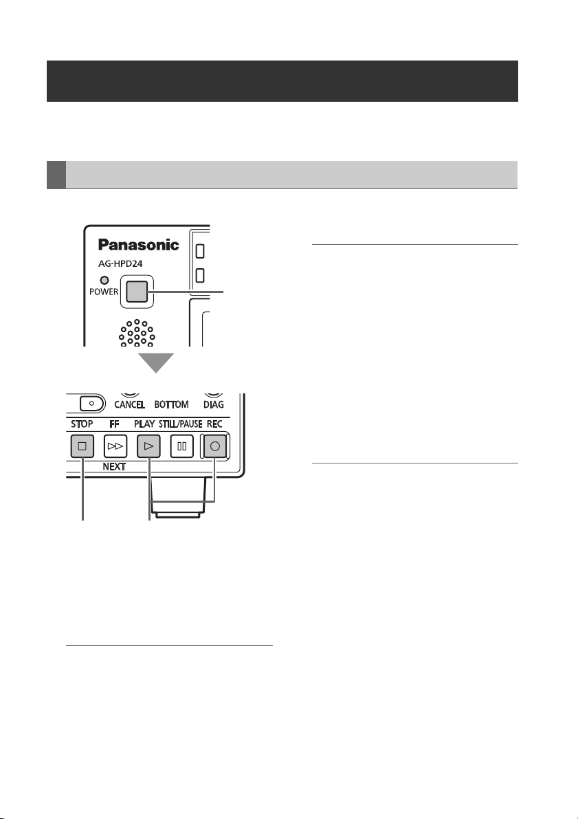
Recording and Playback
When the 3D REC/PB mode is enabled, all operations are performed from the master unit. Slave unit
operations are disabled.
Recording
Master/Slave Unit
ヒ
ビ
1
Master Unit
34
1 Hold each unit’s POWER button for one
second to turn the master and slave units
on.
Set the format, input signal, and etc.
(➝ “Setup Menu” Vol. 2, page 50)
◆ NOTE:
• The recording frequency must be set in the
main mode beforehand.
• Only the AVC-Intra format can be used for
3D recording.
2 Insert P2 cards in the corresponding slots
in both master and slave units.
◆ NOTE:
• Card insertion confirmation on both master
and slave units requires more time than
card confirmation and recording
preparation in normal main mode. If
recording perparation fails, “CANNOT REC”
or “E-62 SLAVE WARNING” may be
displayed.
3 Press the master unit’s REC and PLAY
buttons simultaneously.
Recording begins on the P2 card in the slot
with its access lamp lit orange.
◆ NOTE:
• Recording is disabled when the thumbnail
screen is open. Close the thumbnail screen
before starting to record.
• Recording is disabled when 3D single-
signal output (side-by-side or frame
packing) is enabled.
• LOOP REC and variable frame rate
recording are disabled.
• Recording is possible on the master and
slave unit only for recordable slots (when
the write protect switch is not set to
PROTECT).
• The remaining 3D recording time is the
shortest remaining time on the cards in both
master and slave units.
4 Press the STOP button to stop recording.
3D Signal Recording and Playback: Recording and Playback
44
Page 45

Playback
2
3
4
SDI and HDMI 3D video playback output is
available only during PLAY and STILL/PAUSE.
• Discrete left and right output:
Special playback is only displayed on the LCD,
and is not available as SDI output.
However, video is available at the master unit’s
SDI output when the SETUP - VIDEO -
DISCRETE BLACK menu setting is OFF.
• Single-unit left/right (side-by-side or frame
packing) signal output method:
The LCD monitor displays both L and R special
playback images, but only the L signal is output
(as both L and R images) to SDI/HDMI.
◆ NOTE:
• Clips to be played back can be from different
slots in the master and slave units, but slots for
left and right video must correspond.
• 3D playback requires that the L (left-eye) clip be
present on the master unit, and the R (right-eye)
clip on the slave.
Playback from the Record/Playback
Screen (Thumbnail Screen Off)
Playback from the Thumbnail Screen
Pressing the PLAY button starts playback from
the yellow-framed clip (selected by the cursor
buttons). On the thumbnail screen, clip playback
can be limited and re-ordered by selecting clips
or changing the display.
(➝ “3D Recording/Playback Mode (3D REC/PB)”
Vol. 2, page 37)
◆ NOTE:
• Black numbers indicate clips available for
playback.
• 3D REC/PB mode does not support slot
selection by the THUMBNAIL - SLOT CLIPS
menu setting.
3D Signal Recording and Playback
23
1 Insert a P2 card.
2 Press the PLAY button.
Clips play back in the order they were
recorded on the card.
3 Press the STOP button to stop playback.
3D Signal Recording and Playback: Recording and Playback
1 Insert a P2 card.
2 Use the Up/Down/Left/Right cursor buttons
to place the cursor on a clip to playback.
3 Press the PLAY button.
Playback occurs in the order thumbnails are
displayed.
4 Press the STOP button to stop playback.
The thumbnail screen reappears when
playback stops.
45
Page 46

Displaying 3D Thumbnails
3D thumbnails can be displayed in the same way as normal thumbnails.
Displaying the Thumbnail Screen
1 Turn both master and slave units on by
holding each unit’s POWER button for one
second.
◆ NOTE:
• To cause the thumbnail screen to appear at
power-on, select SETUP - BASIC - POWER
ON GUI, and then THUMBNAIL.
2 Press the THUMBNAIL button.
The thumbnails are displayed.
Press the THUMBNAIL button again to close
the thumbnail screen and return to the
record/playback screen (video).
Thumbnail Screen Names and Functions
◆ NOTE:
• Different points from the main mode’s thumbnail screen are described here. For more details, see
(➝ “Thumbnail Screen” Vol. 2, page 10).
• Only Dual P2 3D clips recorded by this unit or another compatible 3D P2 device are displayed on the
thumbnail screen. Normal P2 clips cannot be displayed, so be careful not to erase them accidentally
when reformatting.
1)
3)2)
4)
1) “3D” Logo
Indicates the 3D status of the displayed thumbnails.
2) Slot status indicators
The M and S indicators show the status of master and slave P2 cards, respectively. For details of
display contents, see (➝ “Thumbnail Screen” Vol. 2, page 10).
3D Signal Recording and Playback: Displaying 3D Thumbnails
46
Pointer (yellow frame)
Selected Clip (blue frame)
Page 47

3) Battery level indicator
Indicates the remaining charge in the master unit’s battery.
◆ NOTE:
• The remaining charge in the slave unit’s battery is displayed on the slave.
4) Dual P2 3D clip fault indicator
This is displayed when there is a problem with a Dual 3D P2 clip, such as reversed left-right card
insertion.
: The clip’s left-channel card is inserted in the slave unit, or the clip’s right-channel card
is inserted in the master unit. Insert the card to the correct unit.
: The clip’s left- or right-channel card is not inserted. Insert the card with the missing clip
channel.
3D Signal Recording and Playback
3D Signal Recording and Playback: Displaying 3D Thumbnails
47
Page 48

Synchronous Playback
Left/right 3D clip pairs not recorded in dual P2 3D mode can be played back using the synchronous
playback (SYNC PB) mode. Connect two AG-HPD24 units in the same way as for 3D REC/PB mode, and
press the MODE button to select the SYNC PB mode for synchronous video playback operation of the
slave with the master unit. However, this mode does not support clip operations other than playback
(that is, recording, copying and deleting).
3D clip content not recorded as a Dual P2 3D clip:
Clips dubbed from material recorded on an AG-3DA1 with their starting points trued up and length set to
be equal using an AJ-HPM200, or clips edited using a non-linear editor and dubbed to a P2 unit that does
not support Dual P2 3D recording.
The L and R clips are required to have the same time code start point, length, and clip sequence.
◆ NOTE:
• Insert the P2 cards with the left-eye (L) and right-eye (R) recordings into P2 card slots on the master
side and slave sides, respectively.
Connections
Connections are the same as for 3D REC/PB mode. (➝ “3D Signal Recording and Playback” -
“Connections” page 39)
Selecting SYNC PB Mode
1 Connect two units according to the
connection examples.
◆ NOTE:
• The system frequency cannot be changed
when SYNC PB mode is enabled. Set the
frequency before selecting the mode.
• Set the master and slave units to the same
frequency.
• The SYNC PB mode cannot be enabled
when the system frequency is set to “59-23”
or “60-24”. Select the frequency to be used
before selecting the SYNC PB mode.
2 Press the MODE button on the master unit.
The mode selection menu appears.
Synchronous Playback: Connections
48
3 Select SYNC PB.
Use the Up/Down cursor buttons to place a
“ ” at SYNC PB, and press the SET button.
4 Both master and slave units restart in
SYNC PB mode.
Page 49

◆ NOTE:
• The SYNC PB mode selection is preserved
internally when power is turned off, and
resumes when power is turned back on. To
return to the main mode from the SYNC PB
mode, turn the power off during the
“WAITING FOR CONNECTION” state, or
press the MODE button after startup in
SYNC PB mode.
• If a LINK cable is not connected, the
“WAITING FOR CONNECTION” state
occurs.
• An error occurs when a connection is
interrupted, such as by disconnecting a
LINK cable. Reconnect the cable and turn
power off and back on.
Vol. 2, page 83)
• An error occurs when the connected units
are not the same model and version.
• If you inadvertently switch to the SYNC PB
mode and activate the “WAITING FOR
CONNECTION” state, turn the power off
and back on to re-enable the (normal) main
mode.
• Power on/off operation is the same as for 3D
REC/PB mode
(➝ “Turning Power On and
Off” page 43).
(➝ “Warning and Error Messages”
Playback
When the SYNC PB mode is enabled, all operations are performed from the master unit. The only
operation available on the slave unit is pressing the THUMBNAIL button to display the thumbnail screen.
• Clip Time Codes
Correctly Synchronizing Playback
Two clips are played back on different devices by
synchronizing the order of the clip numbers,
although the following requirements apply to
obtain correct clip synchronization.
• About the Clip Order
Clips play back in the order they were
recorded. The clips on the P2 card must be in
pairs and the recording dates and times within
each pair must be the same. If the number of
clips or the recording dates and times do not
match, playback order on the master and slave
differs, causing incorrect playback.
• About Clip Length
Each pair of video clips must have the same
starting point and length. If the clip lengths are
different, subsequent playback will be incorrect.
Each pair of recorded clips must have the
same continuous time code. If the time codes
are different or discontinuous, playback cueing
may not operate correctly, causing incorrect
playback.
◆ NOTE:
• When a clip fails to play back correctly, a
warning is displayed, SDI is muted, and black is
output (with DISCRETE L/R setting), or only the
left image is output (with side-by-side or frame
packing settings).
• Playback of mixed-format clips is possible, but
may be discontinuous, and subsequent
playback wil be incorrect.
• Discontinuous time codes may cause an error
code to appear when cueing the start and end
of clips and during frame-by-frame playback of
clips with different start and end time codes. To
recover, press the STOP button and after
Synchronous Playback
Synchronous Playback: Playback
49
Page 50

stopping, select the clips to be paired on the
thumbnail screen and press PLAY or STILL/
PAUSE to synchronize the clips correctly.
Playback from the Playback Screen (Thumbnail Screen Off)
23
1 Insert P2 cards in both master and slave
units.
2 Press the PLAY or STILL/PAUSE button
on the master unit.
Pressing the button automatically cues the
slave position to the master (matches the clip
numbers and time codes). Pressing PLAY
also starts playback.
◆ NOTE:
• When stopped, no image (black screen) is
displayed.
• Signal output is as follows.
Discrete left and right output method:
Special playback video and video when
left and right signals are invalid (such as
TC mismatch) is displayed only on the
LCD monitor, but is not output as SDI.
However, video is available at the master
unit’s SD output when the SETUP - VIDEO
- DISCRETE BLACK menu setting is OFF.
3D single-unit (side-by-side or frame
packing) signal output method:
Special playback video and video when
left and right images are invalid (such as
TC mismatch) appears as both L and R
images on the LCD monitor, but only the L
signal is output (as both L and R images)
to SDI/HDMI.
◆ NOTE:
• When the first position of the master clip is
earlier than that of the slave, the master is
cued to the first position of the slave.
00:00:01:00
00:00:00:00
Master clip
Slave clip
Master playback
Slave playback
Cuing
3 Press the STOP button on the master unit
to stop playback.
Synchronous Playback: Playback
50
Page 51

Playback from the Thumbnail Screen
Master Unit
2
Master Unit
34
1 Insert P2 cards in both master and slave
units.
2 Press the THUMBNAIL button on the
master unit, and move the cursor to the clip
to play back.
◆ NOTE:
• When the clip time codes are different,
incorrect synchronization prevents correct
playback.
• When the first position of the master clip is
earlier than that of the slave, the master is
cued to the first position of the slave.
• The slave unit starts playback from the clip
with the same clip number as on the master.
Synchronous Playback
4 Press the STOP button on the master unit
to stop playback.
◆ NOTE:
• When stopped, no image (black screen) is
displayed.
◆ NOTE:
• All clips are displayed as thumbnails.
• On the slave unit, only the THUMBNAIL and
Up/Down/Left/Right cursor buttons are
enabled for checking clip order. Playback
control is not available on the slave unit
while the thumbnails are displayed.
3 Press the PLAY or STILL/PAUSE button
on the master unit.
Pressing either button automatically cues the
slave position to match the master’s clip
number and time code position.
Pressing the PLAY button also starts
playback.
Synchronous Playback: Playback
51
Page 52

Setup Menu
THUMBNAIL.......................... Thumbnail display selection settings Vol. 2, page 50
OPERATION.......................... Operations such as formatting Vol. 2, page 51
PROPERTY ............................ Displays clip properties Vol. 2, page 53
META DATA .......................... Meta data setting and display Vol. 2, page 54
STORAGE ............................. Storage device operations and display Vol. 2, page 55
SETUP ................................... Various settings Vol. 2, page 56
THUMBNAIL........................ Thumbnail-related settings Vol. 2, page 56
BASIC.................................. Basic operation settings Vol. 2, page 59
TC/UB/CTL .......................... Time-code-related settings Vol. 2, page 62
VIDEO ................................. Video-related settings Vol. 2, page 63
AUDIO................................. Audio-related settings Vol. 2, page 66
DISPLAY.............................. Display-related settings Vol. 2, page 67
LCD ..................................... LCD-related settings Vol. 2, page 69
USER BUTTON ................... User-defined button settings Vol. 2, page 70
SYSTEM .............................. System device settings such as frequency Vol. 2, page 71
FILE ....................................... Saving and loading menu settings Vol. 2, page 74
SYSTEM INFO ....................... Device information display Vol. 2, page 77
52
Setup Menu:
Page 53

Specifications
General
Operating voltage: 7.2 V DC / 7.9 V DC
Power consumption: 19.8 W
indicates safety information.
Ambient operating temperature: 0 °C to 40 °C
Ambient operating humidity: 10 % to 80 % (non-condensating)
Ambient storage temperature: –20 °C to 50 °C (–4 °F to 122 °F)
Mass: 2 kg (4.41 lb) (without battery)
2.3 kg (5.07 lb) (with supplied battery)
Dimensions (W×H×D): 214 mm × 88 mm × 200 mm (8-7/16 inches × 3-7/16 inches ×
7-7/8 inches) (not including the support legs)
Recording media: P2 Card
Recording formats: AVC-Intra 100/AVC-Intra 50/DVCPRO HD/DVCPRO50/
DVCPRO/DV (selectable)
Note: 3D recording in AVC-Intra format only
Video recording signals: 1080/59.94i, 1080/50i, 1080/23.98p, 1080/24p,
720/59.94p, 720/50p, 480/59.94i, 576/50i
Audio recording signals: AVC-Intra 100/AVC-Intra 50:
48 kHz, 16 bits, 8 channels
48 kHz, 24 bits, 4 channels
DVCPRO HD:
48 kHz, 16 bits, 8 channels
DVCPRO50:
48 kHz, 16 bits, 4 channels
DVCPRO/DV:
48 kHz, 16 bits, 2/4 channels selectable
Specifications
Specifications:
53
Page 54

Recording times:
Card Recording format
AVC-Intra 100/
DVCPRO HD
8 GB × 1 Approx. 8 min. Approx. 16 min. Approx. 32 min.
16 GB × 1 Approx. 16 min. Approx. 32 min. Approx. 64 min.
32 GB × 1 Approx. 32 min. Approx. 64 min. Approx. 128 min.
64 GB × 1 Approx. 64 min. Approx. 128 min. Approx. 256 min.
AVC-Intra 50/
DVCPRO50
◆ NOTE:
• The above times apply when single clips are recorded
sequentially on a P2 card.
• Depending on the number of clips recorded, recording time
may be shorter than listed above.
• 3D recording times may be shorter than listed above.
VIDEO
DIGITAL VIDEO
Sampling frequencies: AVC-Intra 100/DVCPRO HD:
(59.94 Hz)
Y: 74.1758 MHz, P
(50 Hz)
Y: 74.2500 MHz, P
DVCPRO50:
Y: 13.5 MHz, P
DVCPRO:
Y: 13.5 MHz, P
Quantization: AVC-Intra 100/AVC-Intra 50: 10 bits
DVCPRO HD/DVCPRO50/DVCPRO/DV: 8 bits
Video compression methods: AVC-Intra 100/AVC-Intra 50:
MPEG-4 AVC/H.264 Intra Profile
DVCPRO HD:
DV-based Compression (SMPTE 370M)
DVCPRO50/DVCPRO:
DV-based Compression (SMPTE 314M)
DV:DV Compression (IEC61834-2)
Color sampling: AVC-Intra 100:
Y:P
B:PR
B/PR
B/PR
= 4:2:2
: 6.75 MHz
: 3.375 MHz
B/PR
B/PR
DVCPRO/DV
: 37.0879 MHz
: 37.1250 MHz
Specifications:
54
Page 55

Resolution: AVC-Intra 100:
1920 × 1080 (1080/59.94i, 1080/50i)
1280 × 720 (720/59.94p, 720/50p)
AVC-Intra 50:
1440 × 1080 (1080/59.94i, 1080/50i)
960 × 720 (720/59.94p, 720/50p)
VIDEO INPUT
Reference input: BNC × 1, Auto switching of black burst / HD 3-value sync
SDI input: BNC × 1
1
: In both 3D REC/PB and SYNC PB modes, when the menu setting SETUP - SYSTEM - FREQUENCY
*
is 59.94 or 50 Hz, black burst is the only acceptable reference signal input.
When the setting is 23.98 or 24 Hz, HD3 value SYNC is the only acceptable reference signal input.
1
*
VIDEO OUTPUT
SD analog composite output: BNC × 1
HD serial digital / SD serial digital
output (switchable):
HDMI port: HDMI × 1 (HDMI type A), 3D supported (VIERA link not
BNC × 1
supported)
• When system frequency is 59.94 Hz
1080/59.94i Frame Packing / Side-by-Side selectable (3D
only)
720/59.94p Frame Packing / Side-by-Side selectable (3D
only)
1080/59.94i, 720/59.94p, 480/59.94p
• When system frequency is 50 Hz
1080/50i Frame Packing / Side-by-Side selectable (3D only)
720/50p Frame Packing / Side-by-Side selectable (3D only)
1080/50i, 720/50p, 576/50p
• When system frequency is 23.98 Hz
1080/23.98p Frame Packing / Side-by-Side selectable (3D
only)
◆ NOTE:
• HDMI output does not support 480i/576i. Convert to 480p/
576p for output.
Specifications
Specifications:
55
Page 56

AUDIO
DIGITAL AUDIO
Sampling frequency: 48 kHz (synchronized with video)
Quantization: 16 bits (DVCPRO HD/DVCPRO50/DVCPRO/DV)
16/24 bits selectabgle (AVC-Intra 100/AVC-Intra 50)
Headroom: 12/18/20 dB (selectable)
De-emphasis: T1=50 µs, T2=15 µs (auto on/off)
AUDIO INPUT
Analog inputs (CH1, CH2): XLR × 2
SDI input: BNC × 1
AUDIO OUTPUT
SDI output: BNC × 1
Monitor outputs: Pin jacks × 2, –10 dBV, 600 Ω
Headphone output: Stereo mini jack (3.5 mm dia.), 8 Ω, variable level
HDMI outputs: 2 channels (linear PCM)
Internal speaker: Round, × 1 (monaural)
OTHER I/O
Time code input: BNC × 1, 0.5 V[p-p] to 8.0 V[p-p], 10 kΩ
Time code output: BNC × 1, low impedance, 2.0 V ±0.5 V[p-p]
RS-422A I/O: 9-pin D-SUB × 1, RS-422A interface
USB HOST: USB 3.0 (Type A) × 1
Connection for USB devices/3D REC/
PB mode/SYNC PB mode:
For 3D REC/PB mode/SYNC PB mode
connection:
For keyboard: USB 2.0 (Type A) × 1 (100 mA maximum)
USB 2.0 Device (Type B) × 1
9-pin D-SUB × 1, RS-422A interface
◆ NOTE:
• This port is intended for keyboard connection.
If the keyboard draws more than 100 mA, a protective
circuit may shut down the machine.
Specifications:
56
Page 57

AC ADAPTOR
Rated input: 100 – 240 V AC, 50 Hz – 60 Hz, 0.55 A
Rated output: 7.9 V DC, 2.53 A
indicates safety information.
Dimensions (W × H × D): 42 mm × 31 mm × 104 mm
(1-5/8 inches × 1-1/4 inches × 4-1/8 inches)
Mass: 220 g (0.48 lb)
BATTERY CHARGER
Rated input: 100 – 240 V AC, 50 Hz/60 Hz, 0.4 A
Rated output: 8.4 V DC, 1.2 A
indicates safety information.
Dimensions (W × H × D): 70.0 mm × 44.5 mm × 116.0 mm
(2-3/4 inches × 1-3/4 inches × 4-9/16 inches)
Mass: 160 g (0.35 lb)
Specifications
Inrush current, measured according to European
standard EN551303-1: 6.5 A
Mass and dimensions are approximate values.
Specifications are subject to change without notice.
Specifications:
57
Page 58

Index
58
■
Number
25M REC CH .................................................... 72
3D connection label ......................................... 17
“3D” Logo .................................................. 46, 37
3D REC/PB ....................................................... 18
3D REC/PB Mode ............................................. 42
3D REC/PB mode/SYNC PB mode
connection .................................................... 56
3D Recording/Playback Mode (3D REC/PB) ... 37
3D Signal Recording and Playback ................. 38
3D Thumbnails ................................................. 46
4:3 MARKER ..................................................... 68
■
A
AC adaptor ................................................ 17, 26
AC power supply cables .................................. 17
Access lamp ..................................................... 21
Accidental Deletion .......................................... 31
Adjusting the recording volume ......................... 6
ALL CLIP .......................................................... 50
Ambient operating humidity ............................. 53
Ambient operating temperature ....................... 53
Ambient storage temperature .......................... 53
ANALOG AUDIO IN jacks ................................ 22
ANALOG AUDIO MON output jacks ................ 22
Analog inputs ................................................... 56
Attaching shot marks ........................................ 17
AUDIO .............................................................. 66
AUDIO INPUT ................................................... 56
Audio level meter display ................................. 45
AUDIO MON button .......................................... 19
AUDIO OUTPUT ............................................... 56
Audio recording signals ................................... 53
AUDIO SMPL RES ............................................ 72
AUTO POWER OFF .......................................... 73
Auto Power Off ................................................. 28
AUTO REC ................................................... 7, 59
AVC-Intra 50 / 100 ............................................ 78
■
B
B CONTRAST ................................................... 69
BACKLIGHT ..................................................... 69
Bad clip ..................................................... 19, 38
Bad clip indicator ............................................. 11
BASIC ............................................................... 59
Battery ....................................................... 24, 25
Battery CGA-D54 .............................................. 17
Battery CGA-D54s ............................................ 17
Battery charger ................................................. 17
Battery latch release button ............................. 23
Battery level indicator ....................................... 47
Battery status .................................................... 45
Battery status indicator .............................. 12, 37
BEEP ................................................................. 61
BRIGHTNESS ................................................... 69
■
C
CANCEL button ................................................ 20
Card .................................................................. 26
Card Status ......................................... 39, 43, 53
CC (F1) BLANK ................................................ 64
Index:
Bold and italicized page numbers (00) indicate pages in Volume 1, while the other
page numbers (00) indicate pages in Volume 2.
CC (F2) BLANK ................................................ 64
CC REC ............................................................ 64
CH1 INPUT LEVEL ............................................ 66
CH2 INPUT LEVEL ............................................ 66
CHANGE PARTITION NAME ............................ 52
Changing slots used for recording ..................... 6
Charging ........................................................... 24
Checking and revising ...................................... 24
Clip Information .................................. 34, 39, 43
Clip meta data ........................................... 20, 21
Clip no. ............................................... 11, 20, 44
CLIP PROPERTY ............................................... 53
Clips .................................................................. 37
CLOCK SET ...................................................... 73
COLOR LEVEL .................................................. 69
Color sampling ................................................. 54
Compression format indication ......................... 44
COMPRESSION MODE .................................... 64
Connecting storage devices ............................ 29
Connection for USB devices/3D REC/PB mode/
SYNC PB mode ............................................ 56
Connections ............................................... 39, 48
CONTRAST ....................................................... 69
COPY ................................................................ 52
Copying Clips ................................................... 18
Copying clips to a storage device .................... 31
Copying to P2 card ........................................... 35
COUNTER button ............................................. 18
Counter value ................................................... 23
COUNTER, RESET/TC PRESET button ............. 18
CROSS HATCH ................................................ 68
CTL ............................................................ 36, 47
CTL DISPLAY .................................................... 62
Cursor control buttons
■
D
DATA DISPLAY ................................................. 56
DATE FORMAT ................................................. 57
Deck Information (DIAG) Icons ........................ 45
De-emphasis .................................................... 56
DELETE ............................................................. 51
DELETE LAST PARTITION ................................ 52
Deleting Clips ..................................... 18, 34, 38
Deleting meta data ........................................... 25
Deleting partition .............................................. 33
Deleting text memos ......................................... 17
Deselecting clips .............................................. 16
DEVICES - SD CARD ........................................ 53
DF MODE .......................................................... 63
DIAG button ...................................................... 19
DIGITAL AUDIO ................................................ 56
DIGITAL VIDEO ................................................ 54
Dimensions ................................................ 53, 57
DISCRETE BLACK ............................................ 64
DISPLAY ........................................................... 67
Display P2 card status for the master side ....... 39
Display P2 card status for the slave side ......... 39
Display status ................................................... 10
Dividing clips .................................................... 30
DOWNCONV. MODE ........................................ 65
Dual P2 3D Clip ................................................ 38
Dual P2 3D clip fault indicator .......................... 47
...................................... 19
Page 59

Duration ............................................................ 10
DVCPRO HD ............................................. 78, 79
DVCPRO50 / DVCPRO DV ............................... 79
■
E
EDH(SD) ........................................................... 64
Edit Copy indicator .......................................... 11
EJECT buttons ................................................. 21
EMBD CH SEL ................................................. 67
Entering a partition name ................................. 33
Error Information ....................................... 83, 89
EXCH.THUMBNAIL .......................................... 52
EXIT button ....................................................... 19
EXIT, CANCEL button ...................................... 19
EXPLORE ......................................................... 55
EXPLORE screen ............................................. 32
EXPORT ........................................................... 55
Exporting .......................................................... 30
EXT TC SEL ...................................................... 63
External mode .................................................. 48
■
F
FF, NEXT button ............................................... 20
FF. REW MAX ................................................... 60
FILE .................................................................. 74
Firmware .......................................................... 90
FORMAT .................................................... 51, 72
Formats ............................................................ 78
Formatting ................................................. 25, 29
Frame-by-frame playback ........................... 8, 15
FREE CAP. OF PARTITION .............................. 53
FREQUENCY .................................................... 71
Frequency indicator ......................................... 45
Full Keyboard ................................................... 80
■
G
G CONTRAST .................................................. 69
GAMMA SELECT ............................................. 66
■
H
HD EMBD LTC ................................................. 63
HD EMBD VITC ................................................ 63
HD Mode .......................................................... 30
HD serial digital ................................................ 55
HD/SD-SDI IN/OUT jacks ................................. 23
HDMI OUT Port ......................................... 23, 40
HDMI outputs ................................................... 56
HDMI port ......................................................... 55
Headphone jack ............................................... 21
Headphone output ........................................... 56
Headroom ........................................................ 56
Hot Swap Recording .......................................... 7
HOUR METER .................................................. 77
■
I
ID OF 9P REMOTE ........................................... 61
Importing .......................................................... 35
Incomplete clip indicator .......................... 11, 21
Incomplete clips ........................................ 19, 38
INDICATOR ...................................................... 56
Information added to clips ............................... 20
Information on operational warnings ................ 84
INITIAL MENU .................................................. 75
INITIALIZE ........................................................ 54
INPUT SEL ................................................. 63, 66
INT SG .............................................................. 63
Internal mode ................................................... 47
Internal speaker ............................................... 56
Items to be displayed as properties ................ 14
■
K
Keyboard ............................................ 56, 58, 80
KEYBOARD port ............................................... 23
■
L
LCD .................................................................. 69
LCD Monitor ..................................................... 33
LEVEL METER .................................................. 67
LINK(D) connector ........................................... 23
LINK(M) port ..................................................... 23
LINK(S) port ..................................................... 23
LOAD .................................................. 54, 74, 76
Loading files ..................................................... 23
LOCAL ENABLE ............................................... 61
LOOP REC .................................................. 7, 59
■
M
MARKED CLIPS ............................................... 51
Mass .......................................................... 53, 57
Master (L) Jack ......................................... 39, 41
MENU button .................................................... 19
Menu Operations .............................................. 32
Menu reset ....................................................... 77
MENU, DIAG button ......................................... 19
Meta data .................................................. 22, 54
Meta data upload file ....................................... 22
MODE button .................................................... 18
MODEL ............................................................. 77
Monitor audio volume adjustment .................... 19
MONITOR CH ................................................... 67
Monitor outputs ................................................ 56
■
N
Numeric Keyboard ........................................... 80
■
O
Open a thumbnail ............................................. 33
Operating status display .................................. 44
Operating voltage ............................................ 53
OPERATION ..................................................... 51
Order of date indication ................................... 13
OSD Display ..................................................... 44
OSD display output .......................................... 12
OSD GRADE .................................................... 67
OSD OUTPUT ................................................... 67
OSD TC SELECT .............................................. 68
OTHER I/O ........................................................ 56
OUTPUT FORMAT ............................................ 65
OUTPUT REF .................................................... 60
OUTPUT SEL ............................................. 40, 64
Overview of all clip playback transitions ............ 9
■
P
P2 Card Access Lamp .............................. 21, 29
P2 Card Recording .......................................... 91
P2 card slot ...................................................... 11
P2 card slots .................................................... 21
P2 Cards ................................................... 29, 39
Index
Bold and italicized page numbers (00) indicate pages in Volume 1, while the other
page numbers (00) indicate pages in Volume 2.
Index:
59
Page 60

60
Partition or folder .............................................. 32
PB POSITION ................................................... 57
PLAY button ...................................................... 20
PLAY DELAY .................................................... 61
Playback .......................... 35, 45, 49, 8, 14, 41
Playback Screen ......................................... 50, 5
Power ......................................................... 27, 43
POWER button .................................................. 21
Power consumption .......................................... 53
POWER lamp .................................................... 21
POWER ON GUI ............................................... 59
Power supply/battery mounting location .......... 23
Preparing for meta data recording ................... 23
PREV button ..................................................... 20
PROPERTY ................................................ 53, 54
PROPERTY DISP. ............................................. 58
PROPERTY SETUP - P2 CARD CAP ................ 53
Proxy indicator .................................................. 11
■
Q
Quantization .............................................. 54, 56
■
R
R CONTRAST ................................................... 69
Rated input ....................................................... 57
Rated output ..................................................... 57
REC button ....................................................... 20
REC FORMAT(HD) ........................................... 72
REC FORMAT(SD) ............................................ 72
RE-CONNECTION ............................................ 52
RECORD ........................................................... 54
Record mode .................................................... 10
Record/Playback Screen .................................. 45
Recording .................................................. 35, 44
Recording clips .................................................. 6
Recording formats ............................................ 53
Recording media .............................................. 53
Recording Times ....................................... 30, 54
Recording/Playback Screen .......................... 5, 6
REF IN jack ....................................................... 22
REF LEVEL ....................................................... 67
Reference input ................................................ 55
Remaining card capacity ................................. 44
REMOTE button ................................................ 18
REMOTE connector .......................................... 23
REMOTE, REF ERROR, TEXT MEMO
indicator ........................................................ 45
REMOTE/MODE button .................................... 18
Removing ......................................................... 31
REPAIR CLIP .................................................... 52
REPEAT PLAY .................................................. 60
Repeat playback ................................................ 9
Reproducing the Time Code and User Bits ..... 49
RESET/TC PRESET button ................................ 19
Resolution ......................................................... 55
REW button ....................................................... 20
REW, PREV button ............................................ 20
RS-422A I/O ...................................................... 56
RUN MODE ...................................................... 63
■
S
SAME FORMAT CLIPS ..................................... 50
Sampling frequency .................................. 54, 56
SAVE ................................................................. 76
Index:
Bold and italicized page numbers (00) indicate pages in Volume 1, while the other
page numbers (00) indicate pages in Volume 2.
SAVE AS ........................................................... 74
SD analog composite output ............................ 55
SD Mode ........................................................... 30
SD serial digital ................................................. 55
SD/SDHC memory card slot ............................. 21
SD/SDHC Memory Cards ................................. 92
SDCARD FORMAT ........................................... 74
SDCARD PROPERTY ........................................ 74
SDI input .................................................... 55, 56
SDI OUT Jack ................................................... 40
SDI output ......................................................... 56
SEEK POS SEL ................................................. 60
SELECTED CLIPS ............................................. 50
Selected number of clips .................................. 11
Selecting clips .................................................. 16
Setting Time Code and User Bits ..................... 47
SETUP ........................................................ 56, 64
SETUP - VERIFY ............................................... 55
Setup Menu ............................................... 52, 50
SHIFT + SET buttons ........................................ 19
SHIFT button ..................................................... 19
Shot mark indicator ........................................... 11
Shot Marks ................................................. 16, 38
SHUTTLE MAX .................................................. 60
Side-By-Side/Frame Packing ............................ 40
Simple property display .................................... 11
Single Clips ....................................................... 15
Slave (R) Jack ............................................ 39, 41
SLOT CLIPS ...................................................... 51
Slot status indicators ........................................ 46
SORT ................................................................ 57
Speaker ............................................................ 21
SPEAKER OUT
Specifications ................................................... 53
Status message ................................................ 11
STILL/PAUSE button ......................................... 20
STOP button ..................................................... 20
STOP EE SEL .................................................... 59
STORAGE ......................................................... 55
Storage device information ............................... 34
Storage device types ........................................ 28
Storage devices ......................................... 11, 27
SYNC PB ........................................................... 18
SYNC PB Mode ................................................ 48
Synchronizing Playback ................................... 49
Synchronous Playback Mode (SYNC PB) ........ 41
SYS H(HD) ........................................................ 72
SYS H(SD) ........................................................ 73
SYSTEM ............................................................ 71
System format ................................................... 10
System format indicator .................................... 45
SYSTEM INFO ................................................... 77
■
T
TC OUTPUT REF .............................................. 63
TC/UB/CTL ........................................................ 62
TCG MODE ....................................................... 62
TEXT MEMO CLIPS .......................................... 51
Text memo indicator ......................................... 11
Text memo location .......................................... 15
Text Memos ............................................... 16, 38
Thumbnail .................................... 11, 20, 50, 56
Thumbnail attributes ......................................... 13
................................................. 67
Page 61

THUMBNAIL button ......................................... 19
Thumbnail Editing ..................................... 22, 39
Thumbnail Screen .... 34, 45, 46, 51, 5, 10, 37
Thumbnail scroll bar ........................................ 12
THUMBNAIL SIZE ............................................ 57
Thumbnail size ................................................. 13
Thumbnail warning information ........................ 87
Time Code .......................................... 36, 44, 47
TIME CODE IN ................................................. 22
TIME CODE IN/OUT Jacks .............................. 22
Time code input ............................................... 56
TIME CODE OUT ............................................. 22
Time code output ............................................. 56
Time display ..................................................... 11
TIMEOUT .......................................................... 69
TOP/BOTTOM buttons ..................................... 19
Total capacity ................................................... 44
Total remaining recording time ........................ 40
Type of thumbnails ........................................... 12
■
U
UBG MODE ...................................................... 62
Unknown clip indicator .................................... 11
UPCONV. MODE .............................................. 65
USB DEVICE .................................................... 18
USB Device ............................................... 37, 36
USB HOST .................................. 37, 56, 45, 55
USB HOST Connector ...................................... 27
USB HOST port ................................................ 21
USB Keyboard ................................................. 81
USB2.0 device port .......................................... 23
Used space ...................................................... 40
User Bits .................................................... 36, 47
USER BUTTON ................................................ 70
USER CLIP NAME ..................................... 23, 54
USER1 ....................................................... 70, 71
USER1-3, 4-6buttons ....................................... 19
USER2 .............................................................. 71
USER3 .............................................................. 71
USER4 .............................................................. 71
USER5 .............................................................. 71
USER6 .............................................................. 71
Using a Keyboard ............................................ 80
■
V
Variable Frame Rate (VFR) Recording ............... 7
Variable speed ................................................. 15
Variable speed playback ..................... 8, 15, 38
VERSION .......................................................... 77
VFR REC .......................................................... 59
VIDEO .............................................................. 63
Video compression methods ........................... 54
VIDEO INPUT ................................................... 55
VIDEO OUT jack .............................................. 23
VIDEO OUTPUT ............................................... 55
Video recording signals ................................... 53
Viewing storage device information ................. 31
VITC BLANK ..................................................... 62
VITC POS-1 ...................................................... 62
VITC POS-2 ...................................................... 62
■
W
Warning information displayed in 3D REC/PB
mode ............................................................ 89
Bold and italicized page numbers (00) indicate pages in Volume 1, while the other
page numbers (00) indicate pages in Volume 2.
Warning information displayed in SYNC PB
mode ............................................................ 89
Warning information for unit status ................... 85
Waveform Monitor (WFM) Display .................... 46
WFM TYPE ........................................................ 68
Wide indicator .................................................. 11
WIDE SEL ......................................................... 64
■
Y
Year, Month, Day and Time .............................. 28
Index:
Index
61
Page 62

63
Page 63

Information for Users on Collection and Disposal of Old Equipment and
used Batteries
These symbols on the products, packaging, and/or accompanying documents mean that
used electrical and electronic products and batteries should not be mixed with general
household waste.
For proper treatment, recovery and recycling of old products and used batteries, please take
them to applicable collection points, in accordance with your national legislation and the
Directives 2002/96/EC and 2006/66/EC.
By disposing of these products and batteries correctly, you will help to save valuable
resources and prevent any potential negative effects on human health and the environment
which could otherwise arise from inappropriate waste handling.
EU
For more information about collection and recycling of old products and batteries, please
contact your local municipality, your waste disposal service or the point of sale where you
purchased the items.
Penalties may be applicable for incorrect disposal of this waste, in accordance with national
legislation.
For business users in the European Union
If you wish to discard electrical and electronic equipment, please contact your dealer or
EU
supplier for further information.
Information on Disposal in other Countries outside the European Union
These symbols are only valid in the European Union. If you wish to discard these items,
please contact your local authorities or dealer and ask for the correct method of disposal.
Cd
Note for the battery symbol (bottom two symbol examples):
This symbol might be used in combination with a chemical symbol. In this case it complies
with the requirement set by the Directive for the chemical involved.
Page 64

■ This product is eligible for the
P2HD 5 Year Warranty Repair
Program. For details, see page 90.
Operating Instructions
Memory Card Portable Recorder
Model No. AG-HPD24P
Model No. AG-HPD24E
Vol.2
Volume
Note that Operation Instructions Vol.2 describes advanced
operations of the Memory Card Portable Recorder.
For instructions on basic operations of the Memory Card Portable
Recorder, refer to Operating Instructions Vol.1 (printed
documents) supplied with the unit.
2
Before operating this product, please read the instructions carefully and save this manual for future use.
ENGLISH
M0711TO0 -PS
VQT3S21A(E)
Page 65

• The SDHC logo is a trademark of SD-3C, LLC.
• HDMI, the HDMI logo and High-Definition Multimedia Interface are trademarks or registered trademarks of HDMI Licensing LLC of
the United States and/or other countries.
•Microsoft
countries.
• Apple and Macintosh are registered trademarks of Apple Inc. of the United States and other countries.
• Microsoft product screen shots reprinted with permission from Microsoft Corporation.
• Names of products, brands, etc., appearing in this manual are trademarks or registered trademarks of their respective owners.
®
and Windows® are registered trademarks or trademarks of Microsoft Corporation® of the United States and/or other
Illustrations in this manual
• Note that illustrations of the unit and menu screens may differ from those you actually see.
Note concerning screenshots in these instructions
• Screenshots from the AG-HPD24P are used in these operating instructions.
Page references
• In this manual, references to pages are indicated as: (➝ page 00).
Terminology
• The term “SD memory card” is used below as a generic term for both SD and SDHC memory cards.
• A memory card with the “P2” logo (for example the separately sold AJ-P2E064XG) is referred to as a “P2 card.”
• A recordable media device such as an external hard disk drive connected to a USB port is referred to as a “storage device.”
• A single continuous video recording is referred to as a “clip.”
• Orange button labels indicate alternate functions enabled by holding the SHIFT button. The operating instructions refer to the buttons
only by label, without mentioning the Shift button.
Website URL
• URL: http://pro-av.panasonic.net/
About copyrights
• Copyright laws may prohibit use, except for personal pleasure, of your recorded video and audio content without permission of the
rights holder.
:
2
Page 66

Contents
Read this first! (For AG-HPD24P)
Volume 1
Power Preparations
Read this first! (For AG-HPD24E)
Read this first!
(For AG-HPD24P/AG-HPD24E)
Usage Precautions
Supplied Accessories, Optional
Accessories
Control Reference Guide
Preparation
Volume 2
Available Modes ...............................................5
Main Mode........................................................6
Recording/Playback Screen ..................................6
Recording Clips ...........................................................6
Playing Back Clips .......................................................8
Thumbnail Screen ...............................................10
Thumbnail Screen Names and Functions .................10
Changing Thumbnail Display ....................................12
Playing back Clips .....................................................14
Selecting and Deselecting Clips ................................16
Attaching Text Memos and Shot Marks ....................16
Copying Clips ............................................................18
Deleting Clips ............................................................18
Repairing and Reconnecting Clips ............................19
Viewing and Revising Clip Information ......................20
Thumbnail Editing ......................................................22
Attaching Meta data to Clips During Recording ........22
Formatting P2 and SD Memory Cards ......................25
Checking Card Status ...............................................26
Connecting an External Device via the USB HOST
Connector ............................................................27
USB Device Mode ..........................................36
Basic Operation
External Connections
3D Signal Recording and Playback
Synchronous Playback
Setup Menu
Specifications
Index
Formatting P2 Cards ................................................. 39
Checking Card Status ............................................... 39
Synchronous Playback Mode (SYNC PB)......41
Playback ............................................................. 41
Displaying and Managing Clips .......................... 43
Changing Thumbnail Display .................................... 43
Playing Back Clips ....................................................43
Playing Back at Variable Speed ................................ 43
Viewing and Repairing Clip Information .................... 43
Checking Card Status ............................................... 43
Screen Display ...............................................44
OSD Display ....................................................... 44
Deck Information (DIAG) Icons ........................... 45
Waveform Monitor (WFM) Display ..................... 46
Time Code, User Bits, CTL.............................47
Time Code ................................................................ 47
User Bits ................................................................... 47
CTL ........................................................................... 47
Setting Time Code and User Bits .............................. 47
Reproducing the Time Code and User Bits .............. 49
3D Recording/Playback Mode (3D REC/PB)..37
Displaying and Managing Clips ...........................37
Thumbnail Screen Names and Functions .................37
Changing Thumbnail Display ....................................38
Selecting and Deselecting Clips ................................38
Playing Back Clips .....................................................38
Variable Speed Playback ..........................................38
Adding Text Memos and Shot Marks ........................38
Copying Clips ............................................................38
Deleting Clips ............................................................38
Repairing and Reconnecting Clips ............................38
Viewing and Revising Clip Information ......................39
Thumbnail Editing ......................................................39
Attaching Meta data to Clips During Recording ........39
Setup Menu ....................................................50
Menu items ......................................................... 50
THUMBNAIL ............................................................. 50
OPERATION ............................................................. 51
PROPERTY .............................................................. 53
META DATA ............................................................. 54
STORAGE ................................................................ 55
SETUP ...................................................................... 56
FILE .......................................................................... 74
SYSTEM INFO .......................................................... 77
List of Compatible Input and Output Formats ...........78
3
Page 67

Contents
Using a Keyboard .......................................... 80
Full Keyboard ............................................................ 80
Numeric Keyboard .................................................... 80
USB Keyboard .......................................................... 81
For Long and Trouble-Free Operation........... 82
Maintenance ....................................................... 82
Condensation ..................................................... 82
Storage Precautions ........................................... 82
Warning and Error Messages ............................ 83
Error Information ....................................................... 83
Detailed Warning and Error Information ................... 84
Error Information ....................................................... 89
Updating the Firmware in This Unit .......................... 90
Handling P2 Card Recording ............................. 91
Use of SD/SDHC Memory Cards ....................... 92
Index.............................................................. 93
4
Page 68

Available Modes
This unit comes with four modes: Main mode, USB device mode, 3D recording/playback mode and synchronous playback
mode. Press the MODE button to select or change modes in the menu that appears.
Each mode enables access to the “thumbnail screen” for displaying, managing and playing back clip thumbnails and the
“recording/playback screen” for recording and playback, while synchronous playback mode provides a “playback screen”.
The figure below shows a schematic diagram of these modes.
• Recording/playback screen: Displays video, time code, remaining battery life and other data and enables recording and
playback.
• Playback screen: Displays video, time code, remaining battery life and other data and enables playback.
• Thumbnail screen: Displays clip thumbnails and properties and manages and plays back clips.
Main mode: Recording and playback on one unit
PLAY
MODE
Recording/
playback screen
THUMBNAIL
Thumbnail screen
STILL
STOP
Playback screen
Available Modes
Mode menu
SET
MODE
USB device mode: Connecting to PC or other devices
3D signal recording/playback mode: Recording/playback 3D signal on two connected units
PLAY
THUMBNAIL
Recording/playback
screen
Synchronous playback mode: Synchronous playback on two connected units
THUMBNAIL
Playback screen Thumbnail screen
Thumbnail screen
STILL
STOP
PLAY
STILL
STOP
Playback screen
Playback screen
Available Modes:
5
Page 69

Main Mode
2
Recording/Playback Screen
Use the recording/playback screen for the following.
• Playing back all cards in the order they were recorded
• Recording to P2 cards
Recording Clips
Use the steps below to record audio and video clips.
Recording is available only in the record/playback screen.
Recording clips
Before you can start recording, you have to set the recording
frequency, format and input signal in a menu.
(➝ Setup Menu “SYSTEM” page 71)
◆ NOTE:
• Recording is not possible on the thumbnail screen or the screens
other than the record/playback screen. On the thumbnail screen,
press the THUMBNAIL button to close the thumbnail screen.
• Selecting analog audio creates an 8-channel audio file where
channels 3 to 8 are mute.
■ Adjusting the recording volume
The level meters show CH1 and CH2 recording volume when
you press the REC VOLUME button (assigned to a USER
button) while the menu setting SETUP - AUDIO - INPUT SEL is
set to analog audio input.
Use the Up/Down cursor buttons to select CH1 or CH2 level
display. Use the Left/Right cursor buttons to adjust the level.
Use the RESET button to restore the UNITY level.
Use the SET and EXIT buttons to return to normal display.
■ Changing slots used for recording
Slots used for recording can be changed during pauses in
recording.
1
23
1 Insert a P2 card.
2 Press the REC and PLAY buttons
simultaneously.
Recording begins on the P2 card in the slot with its access lamp
lit orange.
3 Press the STOP button to stop recording.
1. Assign the SLOT SEL function to a USER button
choosing menu SETUP - USER BUTTON.
(➝ Setup Menu “USER BUTTON” page 70)
2. Press the USER button during a pause in recording.
The slot used for recording changes at each press of the
button.
◆ NOTE:
• When SLOT SELECT is not performed right after changing the
P2 card used for recording and the SETUP - DISPLAY - OSD TC
SELECT menu setting is set to T&S&M, the message “SLOT SEL
INVALID” will appear on the third line of the OSD.
Main Mode: Recording/Playback Screen
6
Page 70

Various types of recording
■ Hot Swap Recording
With a P2 card in both card slots it is possible to make one
continuous recording that spans both cards. You can also
record continuously on 3 or more cards (hot swap recording)
by replacing one card while recording on the other.
◆ NOTE:
• P2 card recognition may be delayed and prevent hot swap
recording depending on when (immediately prior to or after
recording continues onto the other card) a P2 card is inserted in the
empty slot.
A P2 card should be inserted when there is still 1 minute or more
time left on the card that is being recorded.
• This machine does not support hot-swapping during playback.
■ LOOP REC
When a P2 card is inserted in each slot, LOOP REC allows you
to record continuously by successively switching cards.
When available space on the P2 cards has been used up,
recording continues from the first card overwriting previously
recorded loop recording.
Choose the SETUP - BASIC - LOOP REC - ON menu setting to
use the LOOP REC function.
◆ NOTE:
• Turning the unit off turns off the LOOP REC function and it will remain
off when the unit is turned on next time.
• Loop recording requires P2 cards with at least one minute of free
space each.
• During loop recording, the access LEDs for the two P2 cards used
in the recording light orange. Note that removing any of the P2 cards
will terminate loop recording.
• When the SETUP - BASIC - LOOP REC - ON menu setting is
selected, “LOOP” is displayed on the first line of the OSD.
However, if only one card is inserted, or remaining recording time on
a card is less than 1 minute, the LOOP REC function will not work.
even if LOOP REC is set to ON. Then the OSD flashes “LOOP.”
• When the SETUP - BASIC - LOOP REC menu setting is ON, the
standard guaranteed recording time remaining on the P2 cards is
indicated for the selected recording format. When loop recording is
stopped right after deleting old data, the time that remains on the
card may be shorter than indicated.
• Shot marks cannot be added or deleted during loop recording.
• Text memos cannot be added during loop recording.
• LOOP REC is not available during VFR (Variable Frame Rate)
recording.
Terminating Loop Recording Mode
Use one of the following two methods.
• Hold down the POWER button for 2 seconds to turn the unit
off.
• Choose the SETUP - BASIC - LOOP REC - OFF menu
setting.
■ Variable Frame Rate (VFR) Recording
Choose the SETUP - BASIC - VFR REC - ON menu setting to
record only the active frames from the variable frame rate
output of a variable frame rate camera. This enables instant
viewing of slow-motion and fast-motion speed effects
immediately after shooting.
◆ NOTE:
• The VFR function is enabled when the SETUP - SYSTEM - FORMAT
menu setting is 720p, and the SETUP - SYSTEM - FREQUENCY
menu setting is 59 - 23 or 60 - 24.
• Audio and external time codes cannot be recorded in this mode.
• The P2 card that is being recorded cannot be changed during
recording.
• In this mode, the remaining P2 card capacity at 60p (50p), the
slowest slow-speed effect, is indicated.
• When the SETUP - SYSTEM - FREQUENCY menu setting is set to 59
- 23 or 60 - 24, movement in HD SDI video output may look unnatural
when the input frame rate is something other than 24p.
• Changing the frame rate while recording a video signal from a
variable frame rate camera may result in frame loss in the
changeover phase.
■ AUTO REC
When the unit is connected to a camera via SDI, starting and
stopping recording on the unit can be automatically controlled
using the REC START/STOP function on the camera.
23
1. Choose the SETUP - BASIC - AUTO REC menu
setting to make adjustments for the camera.
(➝ Setup Menu “BASIC” - “AUTO REC” page 59)
Main Mode
2. Press the REC button and STILL/PAUSE
button simultaneously to engage REC PAUSE mode.
3. Press the REMOTE/MODE button to set REMOTE.
Now you can start and pause recording on the unit using
the REC START/STOP function on the camera.
Main Mode: Recording/Playback Screen
7
Page 71

Playing Back Clips
2
2
Playback
Before you can start recording, you have to set the playback
frequency, format and input signal in a menu. (➝ Setup Menu
“SYSTEM” page 71)
12
1 Press the PLAY button.
Playback starts. Clips play back in the order they were
recorded.
◆ NOTE:
• Pressing the REW or FF button instead of the PLAY
button results in rewind playback and fast forward
playback, respectively.
• Video and audio playback may be disrupted between clips in
different compression formats (DVCPRO HD, DVCPRO50,
DVCPRO, DV, AVC-Intra 50 and AVC-Intra 100).
• In playback of different clips in the same video format but in audio
recorded at different bit depths, the audio between clips will be
muted.
• Clips with 24-bit audio will be played back as 16-bit audio in
other than normal playback modes engaged using the
PLAY button.
1 Press the Left/Right cursor buttons during playback
or STILL.
Playback changes to high-speed or slow and indicated as
SHTL +/– speed.
2 Press the Left/Right cursor buttons to change
playback speed.
• The playback speed changes each time the buttons are
pressed. Maximum playback speed depends on the
value set by the SETUP - BASIC - SHUTTLE MAX menu
setting (➝ Setting Menu “BASIC” - “SHUTTLE MAX”
page 60).
• Audio is not played back at speeds faster than 10 times
normal speed.
• The Right cursor button changes the speed in forward
direction and the Left cursor button changes the speed
in backward direction.
• Press the STILL/PAUSE button or SET button to pause
playback. To return to normal playback, press the PLAY
button.
• The pulldown sequence may not be uniform for variable
speed playback of native recorded (including x1 speed)
video.
Frame-by-frame playback
2 Press the STOP button.
Playback stops and the input video (EE) appears.
◆ NOTE:
• To show the image where playback stopped (PB image), set
the SETUP - BASIC - STOP EE SEL menu settings to PB.
(➝ Setup Menu “BASIC” - “STOP EE SEL” page 59)
Variable speed playback
Playback speed can be varied to facilitate searches.
1,
Main Mode: Recording/Playback Screen
8
1
1 Press the STILL/PAUSE button to engage still
image mode.
2 Press the Up/Down cursor buttons.
• The Up cursor button performs frame-by-frame playback
in forward direction and the Down cursor button performs
frame-by-frame playback in backward direction.
• Holding down a cursor button results in continuous
frame-by-frame playback. To return to normal playback,
press the PLAY button.
Page 72

Clip and text forward/rewind
4
2
1 Engage playback, still or other image display mode. 2 Press PREV or NEXT.
The clip beginning or text memo position that is located
depends on the value set choosing the SETUP - BASIC SEEK POS SEL menu setting. (➝ Setup Menu “BASIC” “SEEK POS SEL” page 60)
Overview of all clip playback transitions
This unit allows you to vary audio and video playback speed. The figure below shows speed and transition changes.
Data in boxes: Status and speed
Arrows: Possible direction of transition
Arrow text: Cursor button operation
• Asterisks (*) in the diagram indicate stepwise changes in speed.
Example: Pressing the Right cursor button during PLAY results in
double speed playback (SHTL + 2.0) and each press of the button
increases the speed gradually towards the SHTL MAX setting.
Right
–SHTL MAX setting
Right
Left
Right
SHTL + 0.5
SHTL + 0.*SHTL – *
Right
SHTL + 1.0
Left
Right
Right
SHTL + 2.0
Left
Left
+SHTL MAX setting
Left
SHTL + *
Left
Right
PLAY
Left
Main Mode
Right
Rewind by frame
Rewind by clip Forward by clip
Repeat playback
Repeatedly plays back playable clips.
1 Press the MENU button.
Right
Left
SHTL + 0.0
1
Left
UpDown
NEXTPREV
Forward by frame
3 Close the menu.
4 Press the PLAY button to start playback.
All clips will be played repeatedly.
• Repeat playback continues until the STOP button is
pressed.
• Repeated playback is not performed during playback
other than normal playback, for example, variable
playback, and playback stops at the beginning (BOS) or
end (EOS) of a playable clip.
• During repeat playback, “REPEAT” appears in the OSD’s
operating status display.
2 Set the SETUP - BASIC - REPEAT PLAY menu
setting to ON.
Main Mode: Recording/Playback Screen
9
Page 73

Thumbnail Screen
The thumbnail screen enables the following functions:
• Displays clip thumbnails, information, P2 card status and
other data
• Plays back clips on P2 cards
• Simple playback of clips on a storage medium
• Copies and deletes clips
• Formats P2 cards
Thumbnail Screen Names and Functions
171
◆ NOTE:
• Recording cannot start from the thumbnail screen or from playback
of a thumbnail screen. To record, press the THUMBNAIL button to
close the thumbnail screen, then start recording from the recording/
playback screen.
16 1920
8 15 147
7
6
9 10 11 12 13
1. Display status
The following information listed below is displayed on
the screen.
ALL: All clips
SAME FORMAT: Clips with the same format as
the system
SELECT: Clips selected with the SET
button
MARKER: Clips with shot markers
TEXT MEMO: Clips with text memo data
SLOT n: Clips on P2 card in slot No. n
PROPERTY: Detailed clip information
P2 / REMAIN: Media information (amount of
remaining space)
P2 / USED: Media information (amount of
space used)
META DATA: Set meta data
Procedures for switching between displays
(➝ “Changing Thumbnail Display” page 12)
43218
5
2. Record mode
Indicates the record mode of the clip at the cursor
position.
3. System format
Indicates the recording format of the clip at the cursor
position.
4. Duration
Indicates the length (duration) of the clip at the cursor
location and the rough location of current playback.
The playback location is indicated when the SETUP -
THUMBNAIL - PB POSITION - RESUME menu setting
is selected.
(➝ Setup Menu “THUMBNAIL” - “PB POSITION” page
57)
When the playback start position is not the beginning
of the clip, the rough location of the playback position
is displayed.
Main Mode: Thumbnail Screen
10
Page 74

5. Selected number of clips
Indicates the number of selected clips and the total
number of clips.
possible, format the P2 card.
Instead of , appears to indicate that a clip is not
in the P2 standard format.
6. Time display
One of the following data is displayed: the TC (time
code)/UB (user bit) at the start of clip recording/time of
shooting/day of shooting/date and time of shooting/
clip name/the user clip name/slot number.
(➝ “Changing Thumbnail Display” page 12)
7. Thumbnail
Shows the thumbnails recorded for each clip. The
EXCH.THUMBNAIL function allows you to replace this
thumbnail.
(➝ “Changing Thumbnail Display” page 12)
8. Clip no.
Indicates the numbers assigned to P2 card clips,
which are normally assigned starting in order from the
earliest shooting date. Numbers of clips that cannot be
played back are shown in red. You can change the
order clips appear using the display selected clips or
the SORT function.
(➝ “Changing Thumbnail Display” page 12)
9. Shot mark indicator
Indicates that a shot mark has been attached to a clip.
10. Proxy indicator
Indicates clips that contain a proxy video attached by
the AG-HPX370 Series, AJ-HPX3100 or other camera.
◆ NOTE:
• This unit cannot record proxies.
11. Text memo indicator
Indicates a clip that contains text memo data.
12. Edit Copy indicator
Indicates an edit-copied clip.
13. Wide indicator
Indicates a clip recorded in the 16:9 aspect ratio. This
is not indicated for an HD format clip.
14. Incomplete clip indicator
Indicates a clip spanning multiple P2 cards where one
of the cards that contain part of the clip has not been
inserted.
15. Bad clip Unknown clip indicator
Indicates a clip that became defective because the
power was shut down during recording or was
damaged for some other reason. Clips with the yellow
bad clip(
(➝ “Repairing bad clips” page 19)
Clips with the red clip indicator() cannot be
repaired and should be deleted. If deleting is not
) indicator can sometimes be repaired.
16.Indication of P2 card slot and storage device status
The status of P2 card and storage device connections
are indicated as shown below.
–
11 62
(White)
1
(Yellow)
The numbers of P2 card slots that contain
a P2 card are indicated in white.
The number of the P2 card slot of the P2
card that contains the clip at the cursor
position is indicated in yellow. When a clip
spans multiple P2 cards, the numbers of
all the slots housing cards that contain the
clip are indicated.
◆ NOTE:
A slot number with a pink frame indicates either
of the following conditions for an inserted P2
card.
• “RUN DOWN CARD”
The maximum number of overwrites has been
exceeded.
• “DIR ENTRY NG CARD”
The P2 card directory structure does not
conform to standard specifications.
Grey indicates that a storage device is not
connected.
(Gray)
White indicates that a storage device is
available.
(White)
Yellow indicates that clips on a storage
device appear as thumbnails.
(Yellow)
Red indicates that a storage device is
connected but is not available.
(Red)
17.Status message
Shows messages indicating processing status. For
example, screen updating shows an “UPDATING” text
message and a rotating icon.
18.Simple property display
Displays the properties of clips at the cursor location.
A menu allows you to select the information that will
appear.
(➝ “Selecting items to be displayed as properties” page
14)
Main Mode
Main Mode: Thumbnail Screen
11
Page 75

◆ NOTE:
2
4
2
• When there are more characters than can be displayed,
only the range of characters that can be displayed appear.
19.Thumbnail scroll bar
Indicates the location of the currently displayed
thumbnail among displayed thumbnails.
20.Battery status indicator
Displays the following icons to indicate remaining
battery charge.
When the battery is completely depleted the red icons
(or ) appear.
When the AC adaptor is being used, an icon other than
may appear; this is not a sign of
malfunctioning.
Changing Thumbnail Display
The thumbnail screen can be customized to suit operating
conditions and improve efficiency.
Example:
• Set the SETUP - THUMBNAIL menu setting as shown below.
Set INDICATOR to ALL HIDE
Set DATA DISPLAY to CLIP NAME
Set THUMBNAIL SIZE to LARGE
• Set the THUMBNAIL menu setting to SELECTED CLIPS.
Figure showing thumbnail screen example
Setting thumbnails and other OSD display
output
1
1 Press the MENU button.
2 Use the Up/Down/Left/Right cursor buttons to set the
SETUP - DISPLAY - OSD OUTPUT menu setting to
select output (LCD, VIDEO OUT or SDI OUT
connectors) to display thumbnails and other OSD
displays.
Setting the type of thumbnails that open
3
Main Mode: Thumbnail Screen
12
1 Open the thumbnail screen.
2 Press the MENU button.
3 Move the Up/Down/Left/Right cursor buttons to the
type of clips you want to display under THUMBNAIL.
(➝ Setup Menu “THUMBNAIL” page 56)
4 Press the SET button.
Page 76

Setting thumbnail size
5
5
5
4 Press the SET button.
5 Press the MENU button to end processing.
4
3
2,
1 Open the thumbnail screen.
2 Press the MENU button.
3 Use the Up/Down/Left/Right cursor buttons to
choose the SETUP - THUMBNAIL - THUMBNAIL
SIZE menu setting and select the size of clips you
want to display with the cursor.
(➝ Setup Menu “THUMBNAIL” - “THUMBNAIL SIZE” page
57)
4 Press the SET button.
5 Press the MENU button to end processing.
Setting thumbnail attributes
Use the steps below to customize the thumbnail display
format.
Setting order of date indication
Use the steps below to change the order of year, month and
day in date indications.
4
3
2,
1 Open the thumbnail screen.
2 Press the MENU button.
3 Use the Up/Down/Left/Right cursor buttons to
choose the SETUP - THUMBNAIL - DATE FORMAT
menu setting and select the items you need.
Select the items you need and change settings as
required.
(➝ Setup Menu “THUMBNAIL” - “DATE FORMAT” page
57)
4 Press the SET button.
Main Mode
4
3
2,
1 Open the thumbnail screen.
2 Press the MENU button.
3 Use the Up/Down/Left/Right cursor buttons to
choose the SETUP - THUMBNAIL - DATA DISPLAY
menu setting and select the items you need.
Select the items you need and change settings as
required.
(➝ Setup Menu “THUMBNAIL” - “DATA DISPLAY” page
56)
5 Press the MENU button to end processing.
Main Mode: Thumbnail Screen
13
Page 77

Selecting items to be displayed as
3
2
properties
Playing back Clips
Select items that will appear in a simplified property display on
the left side of the thumbnail.
4,5
3
2,6
1 Open the thumbnail screen.
2 Press the MENU button.
3 Use the Up/Down/Left/Right cursor buttons to
choose the SETUP - THUMBNAIL - PROPERTY
DISP. menu setting.
4 Press the SET button to open the setup menu.
All selected items are indicated by check marks.
Playback
1 Open the thumbnail screen.
2 Move the Up/Down/Left/Right cursor buttons to the
clip you want to play back.
5 Press the SET button and add check marks for items
to be displayed.
Pressing the SET button causes unchecked items to be
checked and checked items to be unchecked.
◆ NOTE:
• Up to six items can appear simultaneously.
• When the sixth item has been selected, no other unchecked
item can be selected. Removing the check mark for a checked
item makes it possible to select other items.
6 Press the MENU button to end processing.
3 Press the PLAY button.
Playback starts from the clip the cursor is on. After the clip
at the cursor location has been played, subsequent clips
are played back in order. When the last clip has been
played, the thumbnail screen appears.
◆ NOTE:
• There is no need to select a clip (that is when the thumbnail
appears inside a blue frame) to play it back.
• You can change the thumbnail display settings to play back
clips only from selected slots or play back only clips that contain
text memos.
• You can change the order that clips are played in.
1 Select the clips in the order you want them to be played back.
2 Choose the THUMBNAIL - SELECTED CLIPS menu setting
and the thumbnails will play back only the selected clips in
the selected order.
• Pressing the STILL/PAUSE button instead of the PLAY
button shows a still of the first frame in the clip.
• A clip whose clip number is red cannot be played back.
• Pressing the REW button instead of the PLAY button
results in rewind playback, while pressing the FF results in
fast forward playback.
• Pressing the STOP button during clip playback, stops
playback and the thumbnail screen appears.
Main Mode: Thumbnail Screen
14
Page 78

• When playback stops, the cursor moves to the clip played prior
4
to stopping.
• Video and audio playback may be disrupted between clips in
different video formats (1080i, 720p) or compression formats
(DVCPRO HD, DVCPRO50, DVCPRO, DV, AVC-Intra 50 and
AVC-Intra 100).
• If continuous playback is performed with clips whose video
format is the same but whose audio bit depth is different, the
audio is muted between clips.
• When a 24-bit audio clip is played back in a playback mode
other than the normal mode using the PLAY button, the
audio bit depth becomes 16-bit.
• Changing the thumbnail screen to text memo display makes it
possible to start play back from text memo location.
(➝ “Playing back from text memo location” This page)
• You can select the location from which the thumbnail starts
playback by selecting the SETUP - THUMBNAIL - PB POSITION
menu setting.
(➝ Setup Menu “THUMBNAIL” - “PB POSITION” page 57)
Playing Back Single Clips
When ONE CLIP PLAY is assigned to a USER button, the
USER button allows you to play back the clip at the cursor
location.
Playing back from text memo location
2,3,
2
Main Mode
4
1 Open the thumbnail screen.
2 Press the MENU button to select the THUMBNAIL -
TEXT MEMO CLIPS menu setting.
Thumbnails of clips with text memos appear at the top of
the LCD monitor. Information on the selected clip text
memo appears in the lower half of the LCD monitor.
◆ NOTE:
• The thumbnail screen appears when playback stops at the end of
the clip or when the STOP button is pressed. The cursor then
moves to the next clip.
• All buttons other than the STOP button are not available during
single clip playback.
• Single clip playback starts from the position specified on the PB
POSITION menu setting.
• When JOG/VAR/SHTL is used to display a still image during
playback from the thumbnail screen, the USER button to which ONE
CLIP PLAY has been assigned allows you to play the entire clip to
its end from the still image.
(➝ Setup Menu “USER BUTTON” page 70)
Using variable speed playback and frameby-frame playback
These functions operate in the same manner as in the record/
playback screen.
(➝ “Variable speed playback” page 8, “Frame-by-frame
playback” page 8)
Thumbnail
display
Blue indicates selected
number of text memo clips
and white indicates total
number of text memo clips.
Indicates still images
included with the text
memos.
◆ NOTE:
• When a text memo clip for an AVC-Intra clip with a different
SETUP - SYSTEM - FREQUENCY menu setting is displayed, the
icon may appear at the text memo location in the lower half
of the monitor instead of the thumbnail that should normally
appear.
3 Select the clip (with a text memo) you want play back
and press the SET button.
The cursor moves to the lower half of the LCD monitor.
The cursor moves.
Main Mode: Thumbnail Screen
15
Page 79

4 When the cursor is in the lower half of the monitor,
2
use the Left/Right cursor buttons to select the
thumbnail with the text memo you want to play and
press the PLAY button.
The clip is played back from the text memo time code
location selected with the cursor. When you press the
STOP button to interrupt ongoing playback, or when
playback stops upon reaching the end of the clip, the
thumbnail screen reappears and the cursor returns to the
thumbnail text memo location where playback was
started. Press the EXIT button to return the cursor to the
top of the thumbnail screen.
2 Press the SET button.
A blue frame appears on the clip selected with the cursor
to indicate that it is selected.
◆ NOTE:
• During playback all buttons other than the STOP button are
not available.
Selecting and Deselecting Clips
Select clips you want to process on the thumbnail screen.
Selecting clips
1
1 Use the Up/Down/Left/Right cursor buttons to place
the yellow frame (cursor) on the desired clip.
◆ NOTE:
• Repeat steps 1 and 2 to select multiple clips.
• After selecting a clip, move the cursor to another clip, hold down
the SHIFT button and press the SET button to select another
clip. This method allows you to select the two clips as well as all
the clips between them.
• Selecting a clip updates the number of selected clips shown in
the lower right corner of the screen.
Deselecting clips
1
1 Place the cursor on a selected clip and press the SET
button again.
This cancels the selection.
◆ NOTE:
• Press the TOP/BOTTOM button to move the cursor to the first or
last clip.
Main Mode: Thumbnail Screen
16
◆ NOTE:
• Press the CANCEL button to deselect selected clips.
Attaching Text Memos and Shot Marks
A text memo can be attached in a clip to mark a specific
location. The user can attach shot marks to distinguish clips
from each other. Clips on P2 cards where the write-protect
switch is set to PROTECT cannot be added.
Page 80

Attaching text memos
2
3
2
3
When a text memo is added, you can open a thumbnail at the
text memo location for playback or copying and seek (move)
text memo location by pressing the NEXT/PREV button during
video playback.
(➝ Setup Menu “BASIC” page 59)
1
Assign TEXT MEMO to a USER button.
It is assigned to the USER3 button by default.
(➝ Setup Menu “USER BUTTON” - “USER3” page 71)
2 Press the USER button to which TEXT MEMO has
been assigned during recording, playback or
thumbnail display.
• Press this button during recording and playback where
you want to attach a text memo. The OSD will then show
TEXT MEMO (when successful) or INVALID (when
addition is not possible).
• Pressing this button on the thumbnail screen adds a text
memo at the thumbnail clip location (normally at the
beginning).
◆ NOTE:
• Up to 100 text memos can be attached in one clip.
• Pressing the USER button to which TEXT MEMO has been
assigned during playback may temporarily freeges the
playback screen. This is normal and not a malfunction.
• During LOOP REC, or during recording when the SETUP -
BASIC - VFR REC menu setting is ON, text memo recording is
not available.
2,
Main Mode
1 Change the thumbnail screen to the text memo
display.
2 Use the Up/Down/Left/Right cursor buttons to move
the cursor to the thumbnail you want to delete and
press the SET button.
The cursor moves to the row below.
3 After pressing the SET button to select a thumbnail
for deletion, choose the OPERATION - DELETE
menu setting and press the SET button.
When DELETE is assigned to a USER button, you can
delete the thumbnail by pressing the USER button instead
of making a menu selection.
4 Select YES in the confirmation dialog that appears.
The text memo is deleted.
Attaching shot marks
Attach shot marks to clips to make it possible to distinguish
them from each other.
Deleting text memos
Changing the thumbnail screen to the text memo display
allows you to delete text memos.
1 Assign MARKER to a USER button.
It is assigned to the USER6 button by default.
(➝ Setup Menu “USER BUTTON” - “USER6” page 71)
2 Use the Up/Down/Left/Right cursor buttons to select
a clip.
3 Press the USER button to which MARKER has been
assigned.
Main Mode: Thumbnail Screen
17
Page 81

Each press of this button turns the shot mark indicator on
6
5
and off.
◆ NOTE:
• A shot mark is added to a clip even if the button is pressed in
the record/playback screen.
• When attaching or deleting shot marks for clips that span
multiple P2 cards, be sure to load all the P2 cards that the clip
is recorded on.
• Shot marks cannot be added or deleted during loop recording.
This starts copying.
Copying Clips
Use the steps below to copy clips to P2 cards or storage
devices connected via USB.
◆ NOTE:
• Take care not to turn off the power or remove a card during copying.
Otherwise the copied clip may become bad.
• If the copied clip is bad, delete it and make a new copy.
• Reconnect incomplete clips before copying them.
2,4,5,
2,4,5
3
1 Open the thumbnail screen.
2 Select a clip to copy.
3 Press the MENU button.
4 Use the cursor buttons to choose the OPERATION -
COPY menu setting, select destination from the list
that appears and press the SET button.
• When multiple clips are selected, press the SET button to
view how many clips are selected.
• When clips are copied to a storage device
(➝ “Connecting an External Device via the USB HOST
Connector” page 27), select the destination of the copied
data as required.
• When COPY is assigned to a USER button, you can copy
the thumbnail by pressing the USER button instead of
making a menu selection.
◆ NOTE:
• To interrupt copying, press the SET or the CANCEL button to
cancel the operation. The incomplete copy at the destination is
deleted.
• “OVERWRITE” appears when an attempt is made to place a
copy (having the same GLOBAL CLIP ID) at a destination
already containing an identical item. Select YES to overwrite or
NO to cancel copying and then press the SET button.
6 Press SET button when the completion message
appears.
◆ NOTE:
• No copying is performed when any of the following error
messages appear.
- “LACK OF CAPACITY”
Copy failed because there is not enough space at the copy
destination.
- “UNKNOWN CONTENTS FORMAT!”
Copy failed because the selected clip was bad.
- “NO COPY TO SAME CARD!”
Copy failed because an attempt was made to place the copy
on the same disk.
- “TOO MANY CLIPS!”
Copy failed because too many clips were selected.
• Copying performed in the lower half of text memo display when
the text memo is selected copies the section from the selected
text memo to the next text memo. When there is no text memo
beyond the selected text memo, the section from the selected
text memo to the end of the clip is copied.
Deleting Clips
Use the following procedure to delete a clip from a P2 card.
2,4,
3
5 Select YES in the confirmation message that
appears and press the SET button.
Main Mode: Thumbnail Screen
18
1 Open the thumbnail screen.
Page 82

2 Select the clip to delete.
5
5
3 Press the MENU button.
4 Use the Up/Down/Left/Right cursor buttons to
choose the OPERATION - DELETE menu setting
and press the SET button.
5 Select YES in the confirmation message that
appears and press the SET button.
This deletes all selected clips.
◆ NOTE:
• When DELETE is assigned to a USER button, you can delete the
thumbnail by pressing the USER button instead of making a
menu selection.
• To interrupt deletion, press the SET or the CANCEL button to
cancel the operation. Note that partially deleted clips cannot be
restored by canceling.
Repairing and Reconnecting Clips
Repairing bad clips
appears and press the SET button.
Select NO when you do not want to repair the clip.
◆ NOTE:
• Some clips are so badly damaged they cannot be repaired.
Such clips are indicated by a red .
Reconnecting incomplete clips
Main Mode
A clip spanning multiple P2 cards that cannot be recognized
as a complete clip is marked by the incomplete clip
( indicator). The reconnection function allows you to
reconnect related clips and restore the original clip.
◆ NOTE:
• Incomplete clips occur under the following conditions.
- When the individual clip segments on each P2 card that make up
the clip are copied separately.
- When the clip segments on each card that make up a clip
recorded on multiple cards are separately copied to a storage
device and then copied back to a P2 card.
- When a 5-minute or longer DVCPRO HD or AVC-Intra 100 clip (10-
minute or longer DVCPRO50 or AVC-Intra 50 and 20-minute or
longer DVCPRO or DV clip) is copied to a storage device and
later written back to a P2 card.
This section describes how to restore bad clips that have
been damaged due sudden power outages during recording
or for other reasons. Such clips are marked by the bad clip
indicator (yellow ). Use the following procedure to repair
bad clips.
2,4,
3
1 Open the thumbnail screen.
2 Select the bad clip to repair.
3 Press the MENU button.
2,4,
3
1 Open the thumbnail screen.
2 Select the incomplete clips to reconnect.
◆ NOTE:
• Thumbnails with an incomplete clip indicator( ) are usually
grouped to together.
3 Press the MENU button.
4 Use the Up/Down/Left/Right cursor buttons to
choose the OPERATION - RE-CONNECTION menu
setting and press the SET button.
4 Use the Up/Down/Left/Right cursor buttons to
choose the OPERATION - REPAIR CLIP menu
setting and press the SET button.
5 Select YES in the confirmation message that
5 Select YES in the confirmation message that
appears and press the SET button.
Select NO when you do not want to reconnect the clip.
Main Mode: Thumbnail Screen
19
Page 83

◆ NOTE:
5
• When some but not all the clip segments in a clip that consists
of three or more clip segments are reconnected, the incomplete
clip indicator ( ) will remain.
◆ NOTE:
• Voice memo/Indicator
V
Indicates that a voice memo has been attached to a clip.
This indicator appears only in the clip property mode.
• This unit cannot record and play back voice memos.
Viewing and Revising Clip Information
Viewing clip meta data
Detailed clip information can be displayed on the screen.
5
2,4,
3
1 Open the thumbnail screen.
2 Use the Up/Down/Left/Right cursor buttons to select
a clip.
4)Clip information
The following information appears.
CLIP NAME: Clip name
START TC: Time code at start of recording
START UB: User bit value at start of recording
DATE: Date recorded
TIME: Time at start of recording
DURATION: Clip length
V_FORMAT: Clip recording format
FRAME RATE: Playback frame rate
REC RATE: Recording frame rate
5)Clip meta data
This area shows more detailed information on a clip.
5 Browse the clip meta data as necessary.
3 Press the MENU button.
4 Use the Up/Down/Left/Right cursor buttons to
choose the PROPERTY - CLIP PROPERTY menu
setting and press the SET button.
This displays information on the selected clip.
3)
1)
2)
4)
1)Clip no.
2)Thumbnail
3)Information added to clips
Indicates the number of indicators, attached text memos
and voice memos in a clip. The mark appears when
the P2 card where the clip resides is write-protected.
5)
Use the Up/Down/Left/Right cursor buttons to select a
meta data item and press the SET button to view
information similar to that shown below.
GLOBAL
CLIP ID:
USER CLIP
NAME:
VIDEO: Video signal system
AUDIO: Audio channel system and other
Global CLIP ID
(This is a unique number. There is no
clip anywhere in the world with the
same number.)
The name a user assigns to a clip. This
normally includes a GLOBAL CLIP
ID.
(FRAME RATE, PULL DOWN, ASPECT
RATIO)
information
(SAMPLING RATE, BITS PER
SAMPLE)
Main Mode: Thumbnail Screen
20
Page 84

ACCESS: The date of the last update and other
3
information
(CREATOR, CREATION DATE, LAST
UPDATE DATE, LAST UPDATE
PERSON)
DEVICE: Manufacturer, serial number, and
model name of recording equipment.
SHOOT: Date when recording started and
ended, etc.
(SHOOTER, START DATE, END
DATE, ALTITUDE, LONGITUDE,
LATITUDE, SOURCE, PLACE NAME)
SCENARIO: Program name, scene number, and
other information.
(PROGRAM NAME, SCENE NO.,
TAKE NO.)
NEWS: Reporter, purpose and object
MEMO: Text memo number, OFFSET,
PERSON, TEXT
◆ NOTE:
• Location is indicated in frame numbers
from the start.
• Up to 1000 characters of text can be
added, but only the first 500 characters
will be displayed.
• Use the Left/Right cursor buttons to move
text numbers.
THUMBNAIL: Frame location (normally, start: 0) of
video that makes up the thumbnail and
its size (width, height)
PROXY: Detailed information on proxy data
(format, video codec, etc.)
◆ NOTE:
• Bold items indicate clip meta data that can be changed.
Changing clip meta data
Use the steps below to change clip meta data.
3
2,
2 Use the Up/Down/Left/Right cursor buttons to select
the meta data you want to revise and press the SET
button.
Data that can be revised is indicated as “TEXT”, like in the
illustration below.
Main Mode
3 Use the Up/Down/Left/Right cursor buttons to move
to the item you want to change and press the SET
button.
The screen for changing meta data appears.
(➝ “Using a Keyboard” page 80)
4 Select OK after completing your changes.
Changes made to the meta data are saved to the clip and
the meta data display reappears.
Use EXIT to cancel the entry and return to the previous
display.
◆ NOTE:
• To delete latitude and longitude, enter a blank for altitude. They
cannot be deleted separately.
• Note that the meta data of an incomplete clip with an
indicator cannot be revised. Insert the P2 card/s with the
remainder of the clip.
• MEMO of meta data item to which a 100 character or larger
memo has been attached cannot be revised.
1 Display clip meta data.
5 Press the EXIT button to end processing.
5
Main Mode: Thumbnail Screen
21
Page 85

Thumbnail Editing
7
Use the following steps to change a thumbnail of video at a
location to which a text memo has been attached.
2,3,6,7
2,3,4,6,
2,5
◆ NOTE:
• The THUMBNAIL field in the clip property display shows the
change in thumbnail location (number of frames from the
start). The number for a normal first thumbnail is 0.
• Playback starts from the beginning of the clip regardless of
a change in thumbnail location.
• When a text memo clip for an AVC-Intra clip with a different
SETUP - SYSTEM - FREQUENCY menu setting is displayed, the
icon may appear at the text memo location in the lower half
of the monitor instead of the thumbnail that should normally
appear.
Attaching Meta data to Clips During Recording
1 Attach a text memo to video you want to edit.
(➝ “Attaching text memos” page 17)
2 Change thumbnail display to text memo display.
Choose the THUMBNAIL - TEXT MEMO CLIPS menu
setting.
3 Use the Up/Down/Left/Right cursor buttons to move
to the thumbnail you want to change and press the
SET button.
The cursor moves to the row below.
4 Use the Left/Right cursor buttons to the thumbnail
you want to change.
5 Press the MENU button.
6 Use the Up/Down/Left/Right cursor buttons to
choose the OPERATION - EXCH. THUMBNAIL
menu setting and press the SET button.
7 Select YES in the confirmation message that
appears and press the SET button.
The menu closes and the thumbnail reflects the changes
that have been made.
A meta data upload file containing the name of the person
who shot the video, the reporter, the shooting location or a text
memo and other information can be saved to an SD memory
card. This data file can be loaded and recorded as clip meta
data prior to a recording.
Use P2 viewer to create a meta data upload file
↓
Save the file to an SD memory card
↓
Read the meta data upload file to this unit
↓
When video is recorded the meta data will be added to the
resulting clip
Preparing a meta data upload file
Use P2 viewer to create meta data upload files on a PC.
P2 viewer is software that allows you to use a Windows PC for
processing clips recorded on a P2 card. You can download it
from our website free of charge.
For details on URL (➝ “Website URL” page 2).
Install P2 viewer on a PC, create a meta data upload file and
write it to an SD memory card.
◆ NOTE:
• Use the latest version of the P2 viewer.
• For details on how to create a meta data upload file, refer to the help
function in P2 viewer.
• Write the meta data upload file to an SD memory card formatted on
this unit.
(➝ “Formatting P2 and SD Memory Cards” page 25)
Main Mode: Thumbnail Screen
22
Page 86

Setup to attach meta data
■ Preparing for meta data recording
Use this procedure to determine whether or not to attach the
loaded meta data to clip that is recorded.
(➝ Setup Menu “META DATA” page 54)
■ Select method for recording the USER CLIP
NAME
Use this procedure to set the type of data recorded as USER
CLIP NAME.
(➝ Setup Menu “META DATA” page 54)
Choose the META DATA - USER CLIP NAME menu setting
and the META DATA - RECORD menu setting combinations to
record different data.
Incrementing the counter value of the USER CLIP
NAME for clips exceeding 4 GB
In the following case, one shot is recorded as multiple clips
and the counter value is automatically incremented and
recorded for each shot.
• When an 8 GB or larger P2 card is used in this unit and each
continuous recording exceeds a specified time.
(➝ “Dividing clips over 4 GB in length” Vol. 1, page 30).
• When one recording spans multiple cards.
Example of a recording on one P2 card (DVCPRO HD):
REC start
(start of recording)
Recording duration = 6 minutes
Counter value = A
Clip 1
Clip 2
Counter value = A + 1
Stop
(recording stop)
Main Mode
Recording method USER CLIP NAME to be recorded
Clip meta data
RECORD=ON
Clip meta data
RECORD=OFF
■ Counter value
The counter value is indicated as a four-digit number. When
recording method “TYPE 2” is selected for the USER CLIP
NAME in the clip meta data that is loaded, the counter value
is incremented by 1 for each new recording and a new clip is
generated.
Use the following procedure to reset the counter value.
TYPE1 Read meta data settings
TYPE2 Read meta data settings
+ counter value
TYPE1 Same as GLOBAL CLIP
ID
TYPE2 Same as CLIP NAME
1. Press the MENU button.
2. Use the Up/Down/Left/Right cursor buttons to
choose the META DATA - PROPERTY - USER CLIP
NAME menu setting from the meta data screen and
press the SET button.
Approx. 5 min.
Example of recording a clip on two P2 cards:
REC start
(start of recording)
Clip 1
Counter value = A
1st card
A P2 device will indicate the thumbnail and the counter value
of clip 1 when thumbnails and property of the clip are
displayed.
Approx. 1 min.
Stop
(recording stop)
Clip 2
Counter value = A + 1
2nd card
Meta data upload files
■ Loading files
Use the following procedure to load meta data from an SD
memory card.
3. Use the Up/Down/Left/Right cursor buttons to
choose COUNT RESET and press the SET button.
The counter value is reset to 1.
4. Press the EXIT button to end processing.
4,5,6
3,7
1. Insert the SD memory card storing the meta data
upload file.
2. Open the thumbnail screen.
3. Press the MENU button.
Main Mode: Thumbnail Screen
23
Page 87

4. Use the Up/Down/Left/Right cursor buttons to
choose the META DATA - LOAD menu setting and
press the SET button.
■ Checking and revising loaded meta data
Use the following steps to check meta data loaded from an SD
memory card.
3,4
2
5
The meta data name of the meta data upload file on the SD
memory card appears.
◆ NOTE:
• When the metatada name is displayed, use the right cursor
button to show the file name. Use the left cursor button to
show the meta data name.
5. Use the Up/Down/Left/Right cursor buttons to select
the file to load and press the SET button.
6. Select YES in the confirmation message that
appears and press the SET button.
The file is now loaded.
7. Press the MENU button to end processing.
1. Open the thumbnail screen.
2. Press the MENU button and choose the META DATA
- PROPERTY menu setting.
A screen like the one shown below opens to announce that
meta data has been loaded.
3. Use the Up/Down/Left/Right cursor buttons to move
the cursor to the item you want to change and press
the SET button.
Use this function to check loaded meta data settings.
Main Mode: Thumbnail Screen
24
Page 88

4. While viewing meta data settings, use the Up/Down/
4
6
5
Left/Right cursor buttons to move the cursor to the
setting you want to change and press the SET
button.
The on-screen keyboard appears. Make the required
changes.
Formatting P2 and SD Memory Cards
1 Open the thumbnail screen.
4,
3,
2,
Main Mode
◆ NOTE:
<Meta data types that can be set>
• Use the Up/Down/Left/Right cursor buttons to select the
meta data item you want to check and press the SET button
to view related information.
USER CLIP
NAME:
CREATOR: Creator
LAST UPDATE
PERSON:
SHOOT: The person who shot
PLACE NAME: Shooting location
SCENARIO: Program name, scene No., take No.
NEWS: Name of the reporter, purpose of
MEMO: Name of the person who recorded
• Press the EXIT or SET button after confirming to close the
window.
• Select OK after completing all changes.
Loaded USER CLIP NAME, counter
value and recorded data
The person who last updated the
data
data collection, object of data
collection
the text memo and text memo data
5. Press EXIT to exit the meta data confirmation dialog.
2 Press the MENU button.
3 Use the Up/Down/Left/Right cursor buttons to select
the OPERATION - FORMAT - SLOT n menu setting
(“n” indicates the number of the slot containing the P2
card you want to format) and press the SET button.
◆ NOTE:
• Selecting SD CARD will format an SD memory card inserted in
the SD memory card slot.
4 Select YES in the confirmation message that
appears and press the SET button.
Card formatting starts.
◆ NOTE:
• To cancel formatting, select NO and press the SET button.
• Check that no important data remains on a device before
formatting since data erased by formatting cannot be
recovered.
5 When the confirmation message appears, select OK
(and press the SET button).
■ Deleting meta data
Use the following steps to delete meta data stored in the unit
and initialize settings.
(➝ Setup Menu “META DATA” page 54)
◆ NOTE:
• Repeat the procedures in steps 3 to 5 to format P2 cards in other
P2 card slots or SD memory cards.
6 Press the MENU button to end processing.
Main Mode: Thumbnail Screen
25
Page 89

Checking Card Status
2
Use the following steps to view P2 card slot status, P2 card
usage and other card information on the screen.
3
1 Open the thumbnail screen.
2 Press the MENU button.
3 Use the Up/Down/Left/Right cursor buttons to
choose the PROPERTY - CARD STATUS menu
setting and press the SET button.
The status of P2 card will be displayed.
◆ NOTE:
• Choose the PROPERTY - PROPERTY SETUP - P2CARD CAP
menu setting to switch between remaining free space and used
space.
(➝ Setup Menu “PROPERTY” - “PROPERTY SETUP - P2 CARD
CAP” page 53)
2)1)
3)
Or
4)
Main Mode: Thumbnail Screen
26
5)
6)
1)Write protect mark
A write-protected P2 card is indicated by the mark
displayed here.
2)P2 card status
The remaining free memory on the P2 card is
displayed here in the form of a bar meter and a
percentage value.
Memory used on the P2 card is also displayed in the
form of a bar meter and a percentage value.
The following status information may also appear
depending on card status.
Page 90

FORMAT ERROR!: An unformatted P2 card is
inserted.
NOT SUPPORTED!: This unit does not support the
inserted card.
NO CARD!: No P2 card has been inserted.
3)P2 card remaining memory (or memory used)/total
memory
Indicates P2 card remaining free memory (or memory
used)/total memory in time left in minutes. Fractions of
a minute are rounded off on the display so that the sum
total of the remaining memory available for recording
on each P2 card may not tally with the figure for the
total memory.
4)Slot remaining memory (or memory used) total
The figure obtained by totaling the remaining free
memory (or memory used) on the two P2 slots is shown
here.
◆ NOTE:
• Free space of write-protected P2 cards is not included in
the free space total.
Connecting an External Device via the USB HOST Connector
Usable storage devices
The following storage devices can be used.
• Panasonic portable hard disk unit P2 store (AJ-PCS060G)
• Hard disk drives or solid state drives connected via USB
2.0/3.0.
◆ NOTE:
• The unit supports P2 store only in version Ver2.** or later version. P2
store hard disk in Ver1.** cannot be connected. Upgrade a hard
disk using Ver1.** to the latest version before use.
Main Mode
5)Detailed P2 card status
Select the slot of the P2 card whose status you want to
check and press the SET button to view the P2 card
model number and other detailed information.
Press the SET or EXIT button again to close the
detailed information dialog.
6)Card warning messages
This warning appears when the following P2 cards are
inserted.
Open Detailed P2 Card Status for more information on
this warning.
• “RUN DOWN CARD”
The maximum number of overwrites has been
exceeded.
• “DIR ENTRY NG”
The P2 card directory structure is not supported.
4 Press the EXIT button to end processing.
◆ NOTE:
• If the number of clips recorded on a P2 card exceeds the limit,
“OVER MAX NUMBER CLIPS” appears in the detailed P2 card
status indicating that the limit has been exceeded.
Main Mode: Thumbnail Screen
27
Page 91

Storage device types and available functions
Available functions depend on the type of storage device used. “PARTITION:” in the left half of the EXPLORE screen provides
information on the particular storage device that is connected.
(➝ “Viewing storage device information (EXPLORE screen)” page 31)
◆ NOTE:
• The USB 3.0 connector supports USB bus power (5 V, 0.9 A) and may not be enough to start up some storage devices. Should this happen,
provide the storage device with a separate power supply.
• This unit does not support hard disks that are 2 TB (2048 GB) or larger.
Storage device types and available functions
Storage
device type
TYPE S A special disk format for
high-speed writing/loading
data by P2 card unit.
P2STORE The P2 store (AJ-
PCS060G) hard disk.
Cannot be used for writing
data.
FAT A hard disk whose primary
partition is formatted either
using FAT16 or FAT32. The
root partition or
“CONTENTS” directory
under any directory
used.
OTHER Hard disk other than those
above
• NTFS or other hard disk
1
*
Adding clips to a partition will prevent writing back data by the card to that partition.
2
*
This enables up to 100 folders in up to three levels. Folders appear in order from the top level. Long file names and two-byte character file
names are not supported.
Example:
Features Available functions
2
*
is
using a file system other
than FAT16 or FAT32.
Thumbnail
display
MM M M
M
MM
×× × × ×××
P2 card unit Clip unit Playback
P2 ➝ Storage Storage ➝ P2 P2 ➝ Storage Storage ➝ P2
×
M
×
Displaying
3
*
check
1
*
×
MMMMM
MMMM
MMM
clips
Format
×
4
*
M
/CONTENTS Can be displayed
/SAMPLE/CONTENTS Can be displayed
/SAMPLE/20090101/CONTENTS Can be displayed
/SAMPLE/20090101/1200/CONTENTS Cannot be displayed ➝ This is the fourth level and will therefore not appear.
3
*
Audio and video dropouts may occur during playback from a storage device depending on its performance and operating conditions.
Perfect playback cannot be guaranteed.
4
*
2 TB or larger storage devices cannot be formatted.
◆ NOTE:
• Use storage devices under the following conditions.
• Use storage devices within their operating specifications (temperature, etc.).
• Do not install storage devices in locations that are unstable or exposed to vibration.
• Some storage devices and cables may not operate normally.
• Use a storage device with sufficient space for copying.
Main Mode: Thumbnail Screen
28
Page 92

• Do not connect a storage device to hubs or other connections that involve multiple units even if the other units are not powered. Do not connect
7
devices other than storage devices to a storage device via a hub or other device.
• During formatting and copying, do not disconnect cables, do not remove a P2 card that is involved in any of these activities and do not power
off this unit and the storage device. Otherwise this unit and the storage device must be rebooted.
• A storage device is a high-precision instrument whose read and write functions may fail if used in an unsuitable environment. Please note that
Panasonic accepts no liability whatsoever for data loss or other losses either direct or indirect arising from hard disk damage or other defects.
• When data from this unit is copied to a storage device and is edited on another computer, the data may no longer work in this unit and storage
device data may become corrupted.
• Repair bad clips on P2 cards before copying them to a storage device.
• SATA (serial ATA) or PATA (parallel ATA) interface storage devices connected using a USB converter cable may not be recognized.
• Do not connect or disconnect cables during recording or playback with the unit. Recording or playback may not occur normally if you do.
• On some storage devices, performance of the initial playback confirmation after connecting a hard disk may drop.
Main Mode
Connecting storage devices
1 Connect a storage device to the USB 3.0 connector
on the front panel.
ヒ
ビ
Portable storage
device, etc.
2 Set the STORAGE - USB HOST - ENABLE menu
setting.
◆ NOTE:
• When set to ENABLE, recording and EE output is not available.
• Use cables that conform to the USB 3.0 standard when
connecting USB 3.0 storage devices.
USB 2.0 cables, if used, will only provide USB 2.0 transfer
capacity.
Formatting storage devices
Follow the steps below to initialize a storage device in a TYPE
S or FAT format.
◆ NOTE:
• Note that all data on a storage device is deleted when it is formatted.
4,5,6,
3,5
1 Open the thumbnail screen.
2 Connect a USB storage device.
When the storage device is recognized, the status
indication (➝ “Thumbnail Screen Display” Vol. 1, page 34)
turns white (or red).
3 Press the MENU button.
3 The (gray) icon in the upper right corner of the
thumbnail screen for a storage device that is
recognized and can be used changes to (white).
4 Use the Up/Down/Left/Right cursor buttons to
choose the STORAGE - EXPLORE menu setting
and press the SET button.
The EXPLORE screen will now open.
5 Press the MENU button and use the Up/Down/Left/
Right cursor buttons to choose the OPERATION -
FORMAT(STORAGE) menu setting, press the SET
button, select format type (TYPE S, FAT) and press
the SET button.
Main Mode: Thumbnail Screen
29
Page 93

5,6,
7
4
6 Select YES in the confirmation message that
appears and press the SET button.
7 When the confirmation message appears again,
select YES and press the SET button.
The storage device is now formatted.
◆ NOTE:
• Check that no important data remains on a device before
formatting since data erased by formatting cannot be
recovered.
Exporting data by card to a storage device
You can export all data on a P2 card to a storage device
(writing data from a P2 card to the storage device). The result
of copying and the number of copies will vary with the format
of the storage device.
Storage
device type
TYPE S A partition is created by
FAT A separate folder
Copy result Maximum number
of copies
card and all the data
included in the card are
copied to that partition. The
product number and serial
number of the P2 card used
for copying can be checked
on the explorer screen of
this unit.
1
*
is
created for each card and
all data on the card is
copied to this folder. The
folder name can be
checked on the explorer
screen of this unit.
23
100
2
*
1 Connecting a Storage Device
A storage device that is not TYPE S or FAT will be
formatted as a TYPE S or FAT storage device.
(➝ “Formatting storage devices” page 29)
2 Insert a P2 card.
3 Open the thumbnail screen.
4 Press the MENU button.
5 Use the Up/Down/Left/Right cursor buttons to
choose the STORAGE - EXPORT menu setting and
press the SET button.
6 Select the number of the source P2 card slot and
press the SET button.
When the hard disk is in the TYPE S format, selecting ALL
SLOT will result in a batch export of all inserted cards.
7 Select YES in the confirmation message that
appears and press the SET button.
The data will now be exported. A progress bar appears
during exporting.
When the export operation ends, “COPY COMPLETED!”
appears.
1
*
Folders are created in two levels: date (year/month/date),
and time (hour/minute/second).
Example: A folder created at 12:34:56 on March 30, 2011
will have the following structure:
/11-03-30/12-34-56
2
*
Copy volume is limited by the capacity of the storage
device.
Main Mode: Thumbnail Screen
30
◆ NOTE:
• When using TYPE S formatting for exporting, you can have the
system automatically verify (compare) the original P2 card data
with data copied to the storage device after exporting. In the
factory default settings, verify is enabled for export. The export
operation will end earlier when Verify is not on and exported
Page 94

data is not checked.
7
3
2
To disable verify, set the STORAGE - SETUP - VERIFY menu
setting to OFF.
When exporting to a FAT volume, verify is not performed
regardless of this setting.
• To interrupt exporting, press the SET button, select YES in the
CANCEL confirmation that appears and press the SET button
again.
• Data copied from a P2 card will not be affected if processing
should be interrupted during verification.
• When the network and drive assignments on a computer conflict
and a partition cannot be seen, use our drive mount converter
available free of charge from our web site. This allows you to
mount the specified folder when a storage device is connected
to a Windows PC.
Copying clips to a storage device
Use the following steps to copy selected clips rather than
entire cards to a storage device.
2,4,5,6,
2,4,5,6
Main Mode
◆ NOTE:
• A storage device in the FAT format will display the following
folders.
- Root folder
- Up to three levels of folders containing CONTENTS folder
• Copying is not possible on a TYPE S storage device without a
single partition. To enable copying, format using a FAT format or
use EXPORT to create a partition.
6 Select YES in the confirmation message that
appears and press the SET button.
The clip will now be copied. A progress bar appears during
copying.
When the copy operation ends, “COPY COMPLETED!”
appears.
3
1 Connect a Storage Device.
2 Open the thumbnail screen and use the Up/Down/
Left/Right cursor buttons to select the clips you want
to copy and press the SET button.
You can also select multiple clips.
3 Press the MENU button.
4 Use the Up/Down/Left/Right cursor buttons to
choose the OPERATION - COPY - STORAGE menu
setting and press the SET button.
5 Select the destination of the copied clip in the storage
device folder or partition list that appears and press
the SET button.
◆ NOTE:
• To interrupt copying, use the Up/Down/Left/Right cursor buttons
to choose CANCEL and press the SET button. Then select YES
in the CANCEL confirmation that appears and press the SET
button again. The incomplete copy at the destination is deleted.
• When a clip is copied to a TYPE S storage device, it will not be
possible to import data by card to that partition. The card model
number is then displayed as “UNKNOWN”.
7 Press the SET button to complete the operation.
Viewing storage device information
(EXPLORE screen)
Use the steps below to display storage device information,
select display of storage device partition and folder
thumbnails and select the partition and folder to work on
(open the EXPLORE screen).
4
Main Mode: Thumbnail Screen
31
Page 95

1 Connecting a Storage Device.
2 Open the thumbnail screen.
3 Press the MENU button.
NUMBER(NO.): Partition number (1 - )
MODEL: P2 card model name
PARTITION
NAME:
DATE / TIME: Date and time of partition recording
SERIAL: P2 card serial number
Name assigned to partition
(➝ “Entering a partition name” page 33)
4 Use the Up/Down/Left/Right cursor buttons to
choose the STORAGE - EXPLORE menu setting
and press the SET button.
The EXPLORE screen appears.
3)
1)
2)
1) Display status
Indicates that the name of the screen is the EXPLORE
screen for the storage device.
2) Device information
The following information appears.
Storage
device that
makes it
possible to
read and
write data by
card (TYPE
S, P2
STORE).
Storage
device other
than above
(FAT,
OTHER)
PARTITION: TYPE S / P2 STORE
VENDOR: Name of vendor
MODEL: Model name
SIZE: Total capacity (unit: GB)
USED: Memory used (unit: GB)
Used P2 card area
(unit: cards) up to 23
cards
FREE CAP.: Remaining capacity
(Unit: GB)
SELECTED PART.: Number of selected
partitions
PARTITION: FAT/OTHER
VENDOR: Name of vendor
MODEL: Model name
SIZE: Total capacity (unit: GB)
FREE CAP.: Remaining capacity
(Unit: GB)
SELECTED PART.: Number of selected
folders
3) Partition information (for a TYPE S storage device or
P2 store disk)
4)
Folder information (for a FAT type storage device)
: Check marks appear for selected folder.
NUMBER(NO.): Folder number (1 - )
FOLDER NAME: Folder name (does not include
CONTENTS folders)
DATE / TIME: Folder creation date
◆ NOTE:
• Use the Left/Right cursor buttons to toggle between the
partition names and serial names for TYPE S formatted
storage devices.
• The partition information for an invalid partition on a P2
store is indicated in gray.
• Select the PROPERTY - FREE CAP. OF PARTITION menu
setting in the menu to check the remaining capacity of the
partition.
4) Storage device indicator
Indicates whether or not a storage device is connected
and device type.
■ Operations in the EXPLORE screen
Selecting partition or folder as target
Selecting a partition or folder as target allows you to display
all the clips in the selected partition or folder as thumbnails.
(➝ “Thumbnail Screen Display” Vol. 1, page 34)
Use the following steps to select up to six partitions or folders
to use in this way.
2
1
1. Select a partition or folder in the EXPLORE screen.
2. Hold down the SET button (1 sec or longer) to
complete the operation.
A check mark appears on next to the selected
partition or folder.
: Check marks appear for selected
Main Mode: Thumbnail Screen
32
partition.
Page 96

4. Enter a name for the partition and select OK.
The name is assigned to the partition.
Deleting the last partition
Choose the OPERATION - DELETE LAST PARTITION menu
setting (➝ Setup Menu “OPERATION” - “DELETE LAST
PARTITION” page 52) to delete the last partition on a storage
device.
The selected areas remain available until the storage
device is disconnected or the power is turned off. To
release a selected partition, hold down the SET button
again (for 1 sec or longer) in the selected partition.
Use the CANCEL button to cancel all selected areas.
• A warning appears when an attempt is made to select a
7th area.
◆ NOTE:
• A clip recording that spans several partitions including one whose
MODEL has become UNKNOWN
not run as a normal clip.
1
*
When a clip is copied to a TYPE S storage device, the MODEL of
the partition storing the copy changes to UNKNOWN.
• A TYPE S storage device allows you to assign partition names. The
selected partition name appears in PARTITION NAME in the
EXPLORE screen.
Entering a partition name
A name (containing up to 20 characters) can be assigned to
a TYPE S storage device.
1
*
on a TYPE S storage device will
◆ NOTE:
• Move the cursor to the last partition before deleting.
• The last partition can only be deleted on a TYPE S storage device.
This function can delete only the last partition and not any
intermediate partitions.
• Make sure the partition to be deleted does not contain any data you
need as it will not be possible to recover it after deletion.
■ Displaying thumbnails of clips on storage
devices and viewing video on the monitor
Open a thumbnail
You can display thumbnails and manage clips stored on a
storage device in the same way as clips on P2 cards.
1. Open the EXPLORE screen.
A list of partitions and folders appears.
2. Use the Up/Down/Left/Right cursor buttons to
choose the partition or folder where you want to
display thumbnails and press the SET button.
Thumbnails of the clips in the partition or folder will now
appear. Press the EXIT button to return to the EXPLORE
screen.
Main Mode
◆ NOTE:
• The entered partition name appears in PARTITION NAME in the
EXPLORE screen.
1,3
2
1. Place the cursor on the partition in the storage
EXPLORE screen you want to assign a name to.
You can also hold down the SET button to open the
thumbnail list and enter a name for the partition.
2. Press the MENU button.
3. Use the Up/Down/Left/Right cursor buttons to select
the OPERATION - CHANGE PARTITION NAME
menu setting and press the SET button.
The soft keyboard appears.
◆ NOTE:
• When a volume is selected, pressing the SHIFT + SET button will
display the thumbnails for all the selected partitions.
Main Mode: Thumbnail Screen
33
Page 97

EXITSET
1)
1) Clip information
Displays clip properties.
2) Storage device information
TYPE S device
SERIAL: P2 card serial number
MODEL: P2 card model name
SELECTED
PART.:
SELECTED
PART. No.:
NUMBER
(NO.):
DATE / TIME: Date and time of partition recording
VERIFY: Verify setting and result of verification
NAME: User assigned partition name
SIZE / USED /
FREE CAP.:
A check mark appears for the selected
partition.
This indication appears only when multiple
partitions are selected and a list of numbers of
selected partitions is displayed.
Partition no. (1 - )
ON:
FINISHED
ON:
FAILED
OFF: No verification was
Total storage device capacity/used capacity/
remaining capacity
Verification was successful
Verification failed
• “- -” is displayed on P2
store.
performed
NUMBER
(NO.):
DATE / TIME: Date and time of folder created
FOLDER: Folder name
SIZE /
FREE CAP.:
1
*
: Date created is not shown for root.
Folder no. (1 - )
*1
Storage device capacity/remaining capacity
◆ NOTE:
• Use the SHIFT and +/- buttons to move to thumbnail displays on
adjacent partitions or folders without returning to the EXPLORE
screen.
• Change the thumbnail screen display as necessary. These
changes are performed in the same way as when using P2
cards. (➝ “Changing Thumbnail Display” page 12)
• There is a limit of 1000 clips and clips that exceed this limit will
not be displayed.
Viewing Clip Information
Use the steps below to view a variety of meta data on clips
stored on a storage device. It shows information in the same
2)
way as the P2 card clip property.
1. Move the cursor to select a clip in a thumbnail screen
on a storage device.
2. Press the MENU button.
3. Use the Up/Down/Left/Right cursor buttons to
choose the PROPERTY - CLIP PROPERTY menu
setting and press the SET button.
(➝ “Viewing and Revising Clip Information” page 20)
But repairs cannot be made.
Deleting Clips
Use the steps below to delete clips that are no longer
necessary on a storage device.
1. Select a clip to delete on the thumbnail screen on a
storage device.
2. Press the MENU button.
3. Use the Up/Down/Left/Right cursor buttons to
choose the OPERATION - DELETE menu setting
and press the SET button.
4. Select YES in the confirmation message that
appears and press the SET button.
◆ NOTE:
• It may not be possible to delete clips with the (bad clip
indicator) and (unknown clip indicator).
FAT formatted device
SELECTED
PART.:
SELECTED
PART. No.:
Main Mode: Thumbnail Screen
34
A check mark appears for the selected
partition.
This indication appears only when multiple
folders are selected and a list of numbers of
selected folders is displayed.
Page 98

Checking audio and video of a clip
1. Insert the P2 card that will store the imported
partition.
Be sure to insert a formatted P2 card.
2. Connect a storage device.
1,2
1
1. Opening the Thumbnail Screen on a Storage Device
2. Move the Up/Down/Left/Right cursor buttons to the
clip you want to open.
3. Press the PLAY button .
Playback starts from the clip at the cursor position. When
the clip at the cursor location ends, subsequent clips are
played back in order. When the last clip has been played,
the thumbnail screen on the storage device appears.
◆ NOTE:
• To play back a clip, it is not necessary to select it (so that the
thumbnail appears inside a blue frame).
• The thumbnail display settings can be changed to play back
only selected clips or play back only clips that contain text
memos.
• Pressing the STILL/PAUSE button instead of the PLAY
button shows a still of the first frame in the clip.
• To rewind or fast forward, press the REW or FF button
instead of the PLAY button.
• A clip whose clip number is red cannot be played back.
• Pressing the STOP button during clip playback stops
playback and reopens the thumbnail screen.
• When playback is stopped, the cursor moves to the clip played
prior to stopping.
• Audio and video may be distorted during playback between
clips in different video formats (DVCPRO HD, DVCPRO50,
DVCPRO, DV, AVC-Intra 50 and AVC-Intra 100).
• Text memos, meta data or other data cannot be added or
revised.
• When ONE CLIP PLAY is assigned to a USER button, the USER
button allows you to play back the clip at the cursor location.
• Audio and video dropouts may occur during playback on some
storage devices. Use high-speed storage devices to prevent
dropouts. A warning (E-75) appears when video dropouts
occur. Press STOP or other button to close the warning.
3. Select the STORAGE - EXPLORE menu setting to
open the EXPLORE screen.
4. Display a thumbnail of a partition you want to import
in the EXPLORE screen.
5. Choose the OPERATION - IMPORT menu setting.
6. Select the number of the P2 card slot that will store
the imported data and press the SET button.
Importing starts when YES is selected in the confirmation
message.
When the import operation ends, the message “COPY
COMPLETED!” appears.
◆ NOTE:
• When data is imported to a P2 card that differs from the original
P2 card, some clips may become incomplete (showing the
indicator). Then use the reconnection function to rebuild the
clip.
(➝ “Reconnecting incomplete clips” page 19)
• Choose the STORAGE - SETUP - VERIFY menu setting to turn
verification during copying on or off.
• It is not possible to import data by partition between P2 cards
with different model numbers. Copy data by clip.
■ Copying Data to a P2 Card by Clip
Use the steps below to select a clip on a storage device and
copy it to a P2 card.
2,4
3
1. Opening the Thumbnail Screen on a Storage Device
2. Select a clip to copy.
Main Mode
Writing back (importing) data from a
storage device to a P2 card
■ Importing Data by Partition from a TYPE S
storage device and P2 Store
Use the steps below to import (write back data from a storage
device to a P2 card) data by partition (by P2 card) to a P2 card
that has the same model number as the source card.
3. Press the MENU button.
4. Use the cursor buttons to choose the OPERATION -
COPY menu setting, select destination from the list
that appears and press the SET button.
Copying starts when YES is selected in the confirmation
message.
When the copy operation ends, the message “COPY
COMPLETED!” appears.
Main Mode: Thumbnail Screen
35
Page 99

USB Device Mode
2
4
A USB 2.0 connection with a PC allows you to use P2 cards
inserted in the slots on this unit as mass storage. Note that a
separate USB driver (found on the supplied CD-ROM) must
also be installed on the PC.
Use of P2 viewer, which can be downloaded from the
following site, free of charge, allows you to manipulate clips
stored on a P2 card on a Windows PC.
For details on the URL (➝ “Website URL” page 2)
◆ NOTE:
• For details regarding connections, refer to the Operating
Instructions supplied with the PC and the application software.
1,
◆ NOTE:
• Please refer to the operating instructions supplied with your PC
and software.
4 Press the MODE button to return to regular mode.
◆ NOTE:
• Recording, playback and most of other operations are not
available in the USB device mode.
• When using a Windows PC, install the driver using the supplied
CD-ROM.
1 Press the MODE button when this unit is idle.
2 Select USB DEVICE in the confirmation dialog and
press the SET button.
“USB DEVICE” flashes on the LCD monitor to indicate that
the unit is entering the USB host mode. After the mode
switch, “USB DEVICE DISCONNECT” appears on the LCD
monitor.
This message is replaced by a “USB DEVICE CONNECT”
message when the connection with the PC is completed.
◆ NOTE:
• Selecting 3D REC/PB or SYNC PB mode disables mode
changes until communications with the slave device are
established. When an incorrect mode is selected, turn the
power off and then back on again to change modes.
3 Use USB device mode operations.
USB Device Mode:
36
Page 100

3D Recording/Playback Mode (3D REC/PB)
This chapter describes the 3D recording/playback mode and how to record and playback Dual P2 3D clips.
For details on connections, recording and playback operations refer to the following section.
(➝ “3D Signal Recording and Playback” Vol. 1, page 38)
Displaying and Managing Clips
Although display and playback is limited to Dual P2 3D clips, basic operations (in main mode) are the same as for normal clips
except for a few restrictions. The following sections will explain the differences from normal operation (main mode).
Thumbnail Screen Names and Functions
◆ NOTE:
• The thumbnail screen displays only Dual P2 3D clips recorded on this unit or on a 3D compliant P2 device. This mode does not display regular
P2 clips and care is required to avoid formatting such cards.
Pointer (yellow frame)
Selected clip (blue)
3D Recording/Playback Mode (3D REC/PB)
1) “3D” Logo
Indicates that a 3D thumbnail is displayed.
2) Slot status indication
L indicates the P2 card status on master side and R
indicates that on slave side. (➝ For details on displayed
data, see “Thumbnail Screen” page 10).
3) Battery status indicator
Indicates remaining battery capacity on the master unit.
◆ NOTE:
• Battery capacity on the slave unit is indicated on the slave unit.
4) Bad Dual P2 3D clip indicator
Appears when an L or R clip has been inserted incorrectly
or something else is wrong with a Dual P2 3D clip.
An L clip is inserted in a slave unit, or an R clip is
inserted in a master unit. Insert the clips correctly.
No L or R clip has been inserted.
Insert the missing clip.
◆ NOTE:
• If the bad clip indicator (yellow ) appears, repair the clip, see
(➝ Setting Menu “OPERATION” - “REPAIR CLIP” page 52).
3D Recording/Playback Mode (3D REC/PB): Displaying and Managing Clips
37
 Loading...