

Page 1
Operating Instructions
Digital AV Mixer
Model No. AG-HMX100P
Model No. AG-HMX100E
Vol.2
Volume
Note that Operating Instructions Vol. 2 describes advanced
operations of the digital AV mixer.
For instructions on basic operations of the digital AV mixer,
refer to Operating Instructions Vol. 1 (printed document)
supplied with this unit.
2
Before operating this product, please read the instructions carefully and save this manual for future use.
ENGLISH
VQT2U23A-1M0810RI1100 -PS
Page 2
Contents
Volume 1
Requests on Use
Overview
Features/AV Mixer Functions/Accessories/Components
and Functions
Basic Operation
System Configuration Examples/Power-On/Initial Setup/
Switching or Combining of Video
Volume 2
Chapter 1 Applying Effects to Video and
Sound
Setting of Video Switching and Combining Effects .......3
Setting the Transition (Wipe) Pattern [TRANSITION]
Setting the Basic Pattern Key [BASIC PATTERN KEY]/
Pattern Key [PATTERN KEY]
Setting the Chroma Key [CHROMA KEY]
Setting the Luminance Key [LUMINANCE KEY] /
External Key [EXT KEY]
Setting the Title Key [TITLE KEY]
Setting Key Learn [KEY LEARN]
Setting the Downstream Key (DSK)
Setting the Fade [FADE]
Adjusting Input Video
Adjusting Colors of Video [COLOR EFFECTS]
Applying Effects to Video [VIDEO EFFECTS]
Setting Audio Effects
[AUDIO EFFECTS] Menu
.....................................................13
......................................................17
.........................................5
........................6
................................................7
.....................................8
......................................9
..............................11
................................................12
...............................................17
.......3
..............13
................13
Chapter 2 Registering Settings and
Effects
File operation [FILE] ........................................................19
Event Memory Operation
Registering the Current Settings and Created Effects
as Events
Calling Events
Clearing Event Memory..................................................20
Clearing All the Event Memory.......................................21
....................................................................20
................................................................20
................................................20
Before Calling for Service
Specifications
Index
Chapter 3 Switching 3D Video
Example Connections with 3D Camera .........................22
System for Monitoring Program Output as L channel
and Multi-view Output as R Channel (Simultaneous
Display of L and R Channels)
System for Displaying Program Output and Multi-view
Output on Different Monitors (Use of SIDE BY SIDE
Signal)
.........................................................................23
System Configured with 2 Units of AG-HMX100P/
HMX100E and 4 Cameras
Setting 3D Mode [3D]
......................................................25
....................................22
.......................................... 24
Chapter 4 Operating Environment Setting
Setting the System ..........................................................26
Setting [SYSTEM1]
Setting [SYSTEM2]
Setting [MEMORY]
Setting the Audio Level [AUDIO LEVEL]
Setting for External Synchronization [GEN LOCK]
Setting Details for Connecting PC [PC2]
Setting for External Interface
Setting [RS-232C]
.........................................................26
.........................................................26
.........................................................27
........................27
......28
.......................28
.........................................28
..........................................................29
Index
List of Transition Patterns
List of Key Patterns
2
Page 3
3
Chapter 1 Applying Effects to Video and Sound
MODIFY
OFF
OFF
EFFECTS
EDGE
HARD
PATTERN COLOR
WHITE
WIDTH
0
POS.
EVENT
TRANSITION
ME TIME PATTERN INT
00 E
1:00 F 0001
WHT
X 128
Z 196
Y 128
OFF
COMP
SLIDE
MULTI
BLINDS
MODIFY
OFF
Chapter 1 Applying Effects to Video and Sound
This chapter describes how to apply effects to video, give changes to transition, and perform various types of keying and
title insertion as well as explaining audio mixing.
Setting of Video Switching and Combining Effects
This section describes the method of selecting and
processing a pattern used for video switching.
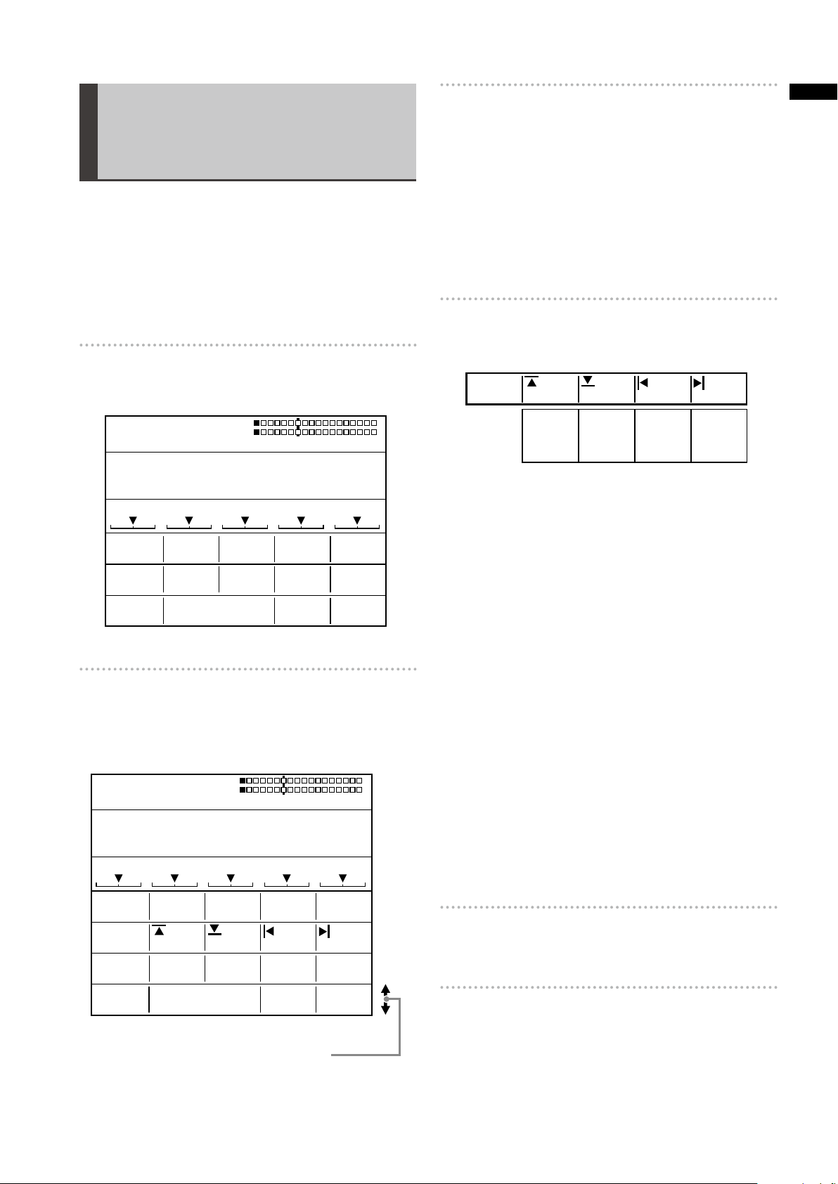
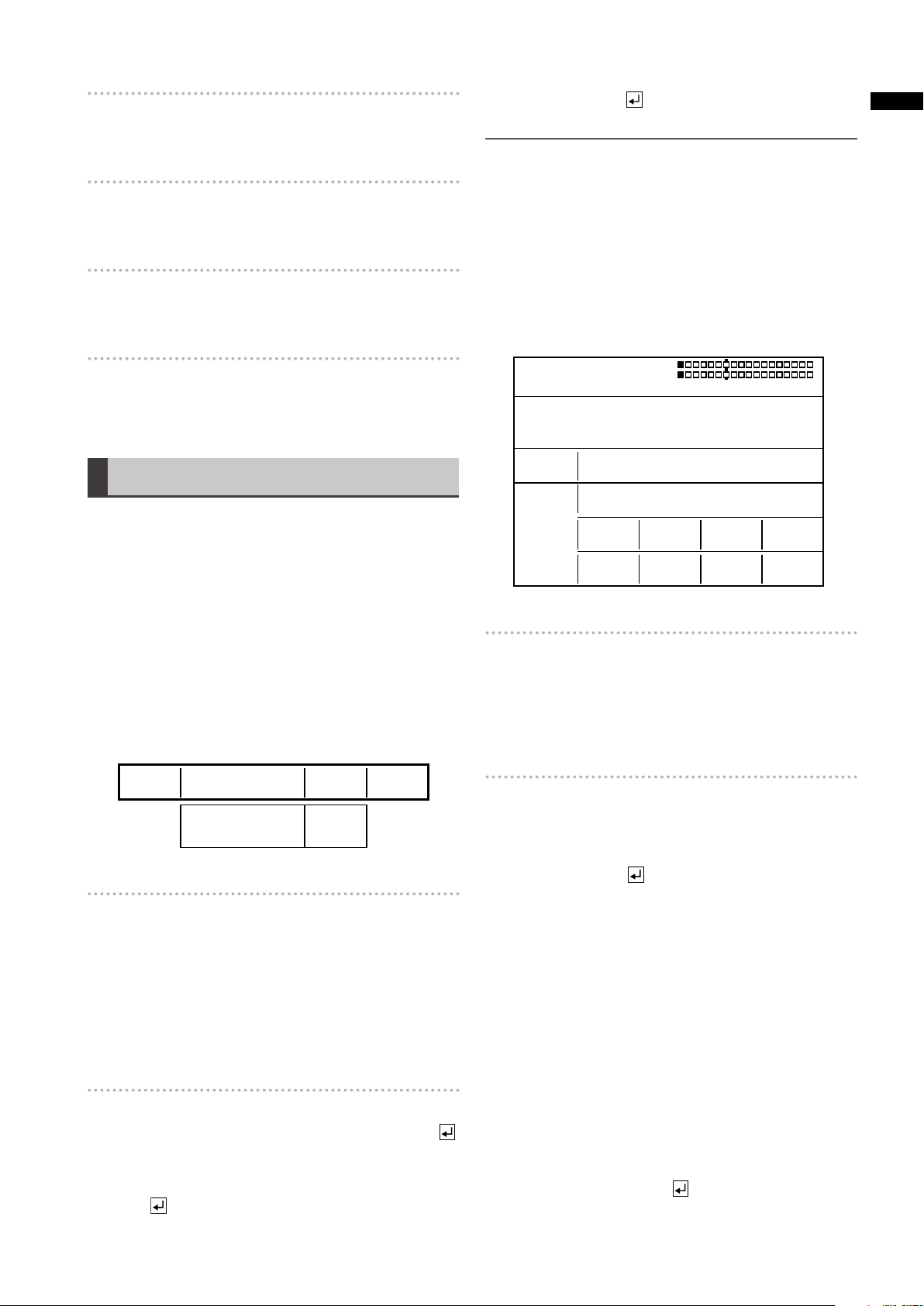
Setting the Transition (Wipe) Pattern [TRANSITION]
The [TRANSITION] menu is used to process a pattern used
for transition wipe.
This menu appears when one of No. 1 to No. 1550 patterns
is selected.
For pattern numbers, refer to “List of Transition Patterns”
at the back of Volume 2.
For selecting patterns, refer to “To select a pattern”
(page Vol.1-35).
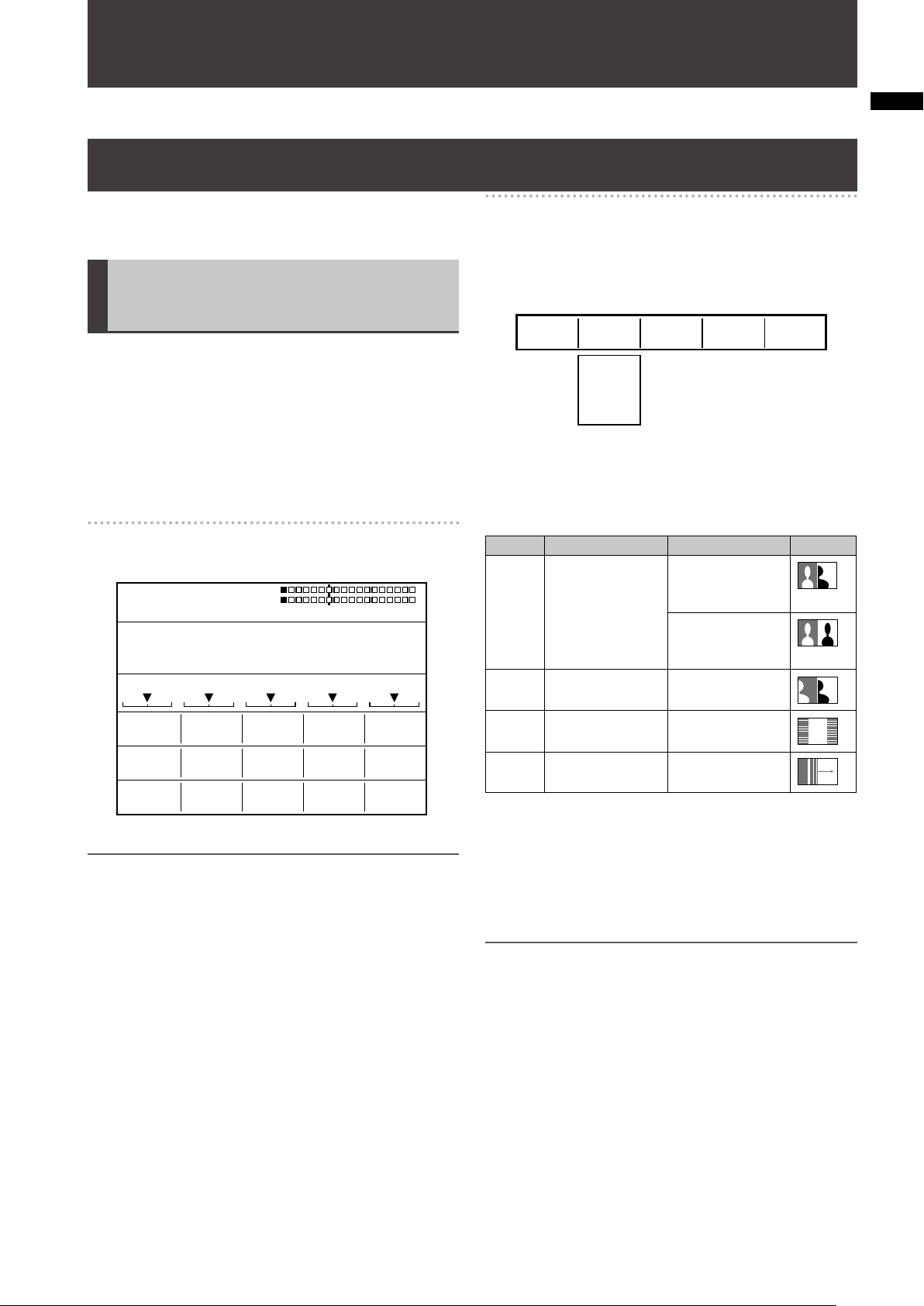
[TRANSITION] menu
The items which can be set vary with the selected pattern.
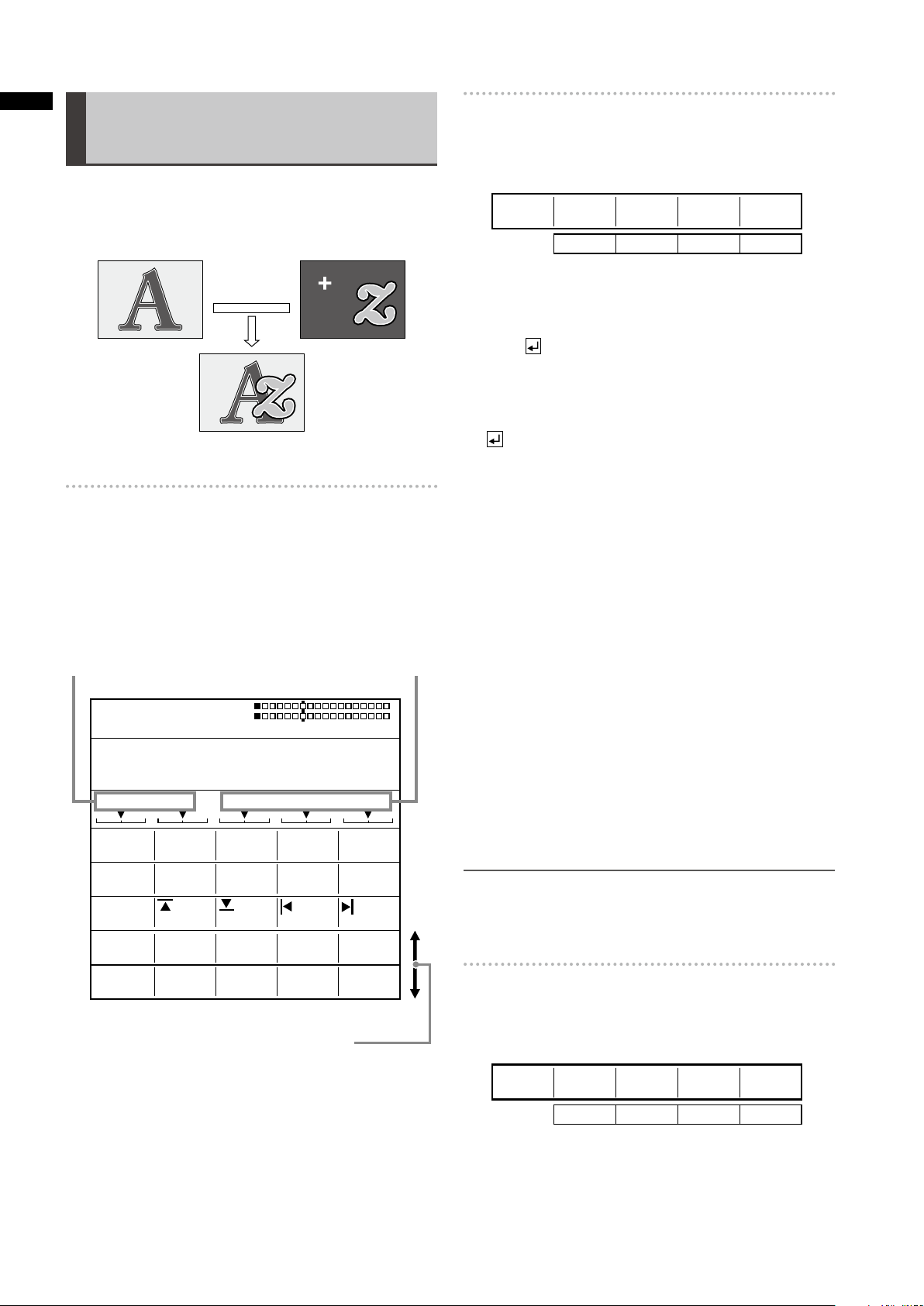
[MODIFY]
Settings can be made only for the basic patterns (the
patterns shown as “Basic” in “List of Transition Patterns” at
the back of this document) and their related patterns.
Rotary 1 Rotary 2 Rotary 3 Rotary 4 Rotary 5
Select the effect to be applied to the pattern using the
rotary 2 control.
When [COMP] is selected, the effect level ([SINGLE] or
[DOUBLE]) can be set with the rotary 3 control.
Modify Description Level Example
COMP Reduced wipe [SINGLE]: Only
one image is
reduced in size.
[DOUBLE]:
Both images are
reduced in size.
SLIDE Sliding one image
into another
MULTI Vertical-striped
wipe
BLINDS Blind-type wipe None
None
None
NOTE
When a transition pattern in the range of No. 200 to No. 222
(1001 to 1004, 1021 to 1023, 1030 to 1034, and 1059 to 1069)
is selected, transition mix is performed. (The MIX button is
lighted.)
Of these patterns, when a pattern performing effects in which
video and color effects are combined is selected, the VIDEO
EFFECTS or COLOR EFFECTS button is lighted if turned
off, and the [VIDEO EFFECTS] or [COLOR EFFECTS] menu
appears.
The factory default setting is [OFF].
The List of Transition Patterns at the back of this document
can be used to check the basic patterns and those with
the Modify effects added. (Example: When SLIDE as the
MODIFY effect is applied to the No. 1 basic pattern, the No.
43 pattern is generated.)
NOTE
If any change is made to [MODIFY], the pattern number is •
also changed automatically.
When the internal video is selected as the video source after •
switching, the image is not reduced in size, but becomes
the same state as [SINGLE] is selected even if [BOTH] is
selected for [COMP].
When one of the patterns in the range of No. 28 to No. 41 •
(1501 to 1510 and 1521 to 1530), No. 32 to No. 35, and No.
130 to No. 133 (1541 to 1548) with the [COMP] effect set is
selected to use an input video source reduced in size, the
multi-strobe effect in the [VIDEO EFFECT] menu cannot
be applied. Even if the multi-strobe effect is selected, it is
disabled when the transition lever is operated.
Page 4
4
Chapter 1 Applying Effects to Video and Sound
[PATTERN EDGE]
HARD
SOFT
BORDER
SOFT BORDER
1-255 WHITE
YELLOW
CYAN
GREEN
MAGENTA
RED
BLUE
BLACK
CUSTOM1
CUSTOM2
PATTERN
HARD
EDGE
COLORWIDTH
32 WHITE
OFF
SHADOW
TRAIL
EFFECTS
OFF
EFFECTS
SHADOW
SELF
SELF-SPARK
BODM
BODM-SPARK
1-32
EFFECTS
TARIL
TIME
SELF 16
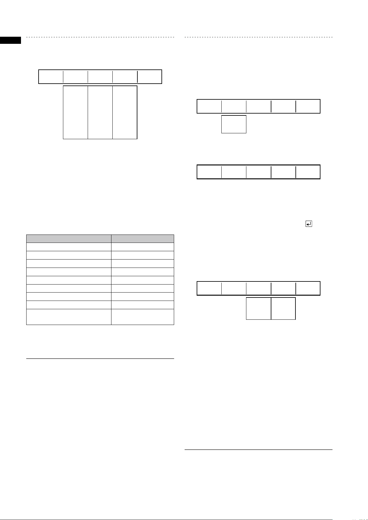
An edge can be added to a pattern.
Rotary 1 Rotary 2 Rotary 3 Rotary 4 Rotary 5
Select the edge of transition patterns from [HARD], [SOFT],
[BORDER], and [SOFT BORDER] using the rotary 2 control.
The factory default setting is [HARD].
Set [WIDTH] in the range of 1 to 255 using the rotary 3
control.
The factory default setting is 32.
For No. 701 to No. 707 (24 to 27) and No. 801 to No. 814
(183 to 196) patterns, [WIDTH] can be set only to 1 or 2.
Use the rotary 4 control to set [COLOR] (color of the edge)
to one of the colors in the table shown below.
Setting Color
[WHITE] (factory default setting) White
[YELLOW] Yellow
[CYAN] Cyan
[GREEN] Green
[MAGENTA] Magenta
[RED] Red
[BLUE] Blue
[BLACK] Black
[CUSTOM1] or [CUSTOM2] Grey as the factory
default setting
When [CUSTOM1] or [CUSTOM2] is selected, the same
color as set in the [BACK MATTE] submenu of the [INT
VIDEO] menu is applied (
NOTE
If the PinP pattern is selected and Still is applied to source •
video B, Still is cancelled at the same time as the transition
lever is operated. (The PinP pattern and Still cannot be used
as the same time.)
[SOFT BORDER] cannot be selected for No. 701 to No. 707 •
(24 to 27) and No. 801 to No. 814 (183 to 196) patterns.
page Vol.1-29).
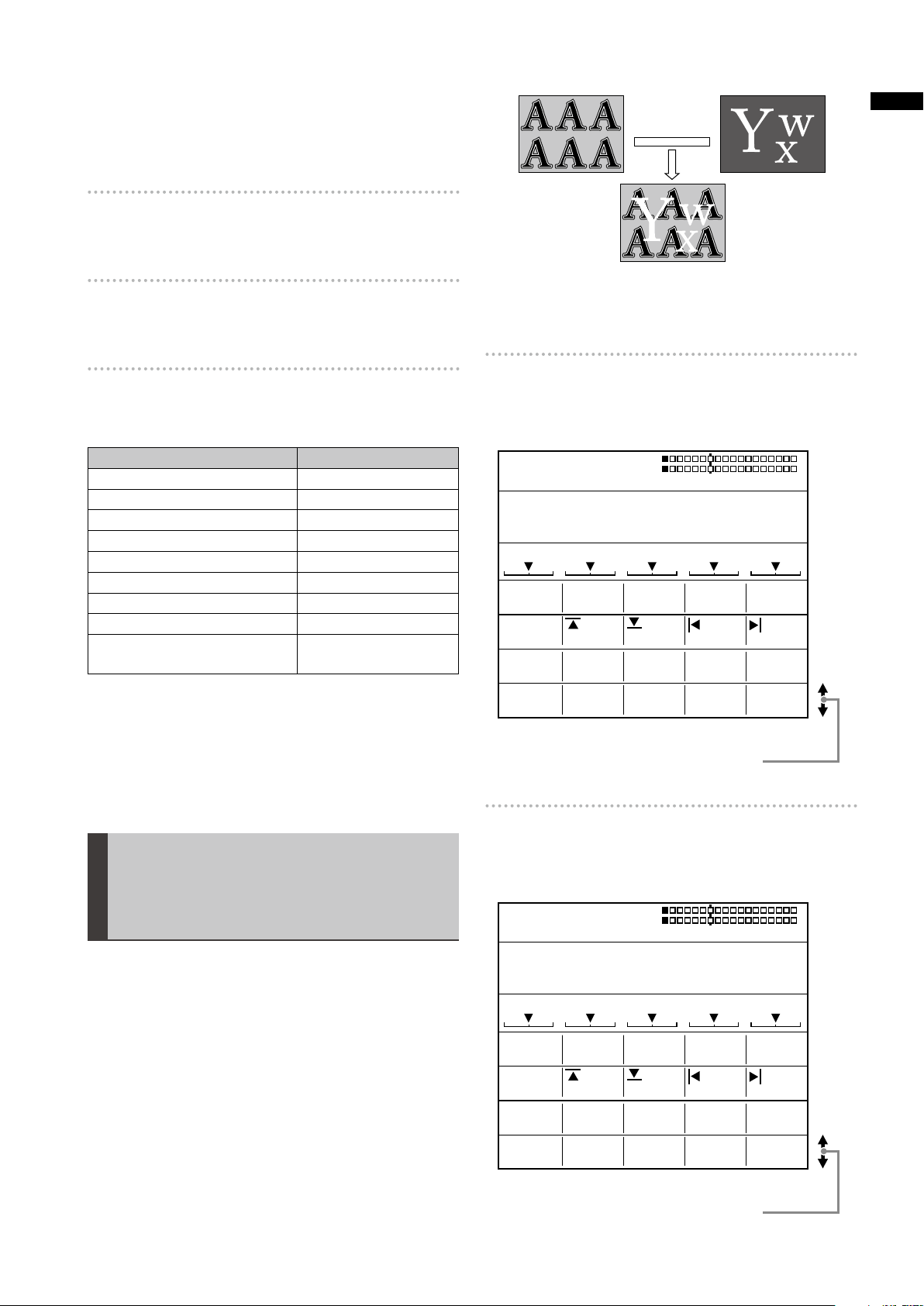
[EFFECTS]
Select the effect of [SHADOW] or [TRAIL] using the rotary
2 control.
SHADOW: Adds black shadow to the pattern.
TRAIL: Leaves trails of the moving pattern.
Select [OFF] to apply no effect.
Rotary 1 Rotary 2 Rotary 3 Rotary 4 Rotary 5
If [SHADOW] is selected
Rotary 1 Rotary 2 Rotary 3 Rotary 4 Rotary 5
Set the position of the shadow by operating the joystick
while holding down the SHIFT key.
The CENTER, SCENE GRABBER, and HOLD buttons flash
temporarily.
To cancel the shadow position setting, press the
while holding down the SHIFT key in the state where
[FEECTS] is selected (inverted to black). At the same
time as the setting becomes [OFF], the specified shadow
position is reset.
If [TRAIL] is selected
Rotary 1 Rotary 2 Rotary 3 Rotary 4 Rotary 5
Select the spark for the trail (the twinkling effect of trails)
from [SELF] (original video), [SELF-SPARK] (spark of
original video), [BODM] (border color), and [BODMSPARK] (border spark) using the rotary 3 control.
When [BODM] or [BODM SPARK] is selected, the color set
in the [PATTERN EDGE] submenu of the [TRANSITION]
menu is used as the border color.
Set the continuation time of the trail in the range of 1 to 32
using the rotary 4 control.
To set the offset position of the trail, operate the joystick
while holding down the SHIFT key.
The CENTER, SCENE GRABBER, and HOLD buttons flash
temporarily.
The offset position setting can be cancelled in the same
way as for canceling the shadow position setting.
key
NOTE
The trail or shadow settings are canceled when TRAIL or
SHADOW is selected in the [DSK EFFECTS] submenu of the
[DSK FADE] menu or when the multi-strobe effect or DECAY is
selected in the [VIDEO EFFECTS] menu.
Page 5
5
Chapter 1 Applying Effects to Video and Sound
Setting the Basic Pattern Key
PATTERN COLOR K LEVEL
HARD WHITE 255
SETUP
OFF
LEARN
EDGE 16
EFFECTS
WIDTH
KEY
POS.
EVENT
BASIC PATTERN KEY
ME TIME PATTERN INT
00 E
1:00 F 3001
WHT
X 128
Z 196
Y 128
9000
EMPTY
PATTERN COLOR K LEVEL
HARD WHITE 255EDGE 16
WIDTH
SETUPLEARN
KEY
POS.
0
CROP
EFFECTS
OFF
000
EVENT
PATTERN KEY
ME TIME PATTERN INT
00 E
1:00 F 3301
WHT
X 128
Z 196
Y 128
9000
EMPTY
0-243(480i)
0-288(576i)
0-720(720p)
0-540(1080i)
0-243(480i)
0-288(576i)
0-720(720p)
0-540(1080i)
0-720(480i)
0-720(576i)
0-1280(720p)
0-1920(1080i)
0-720(480i)
0-720(576i)
0-1280(720p)
0-1920(1080i)
CROP
0
00 0
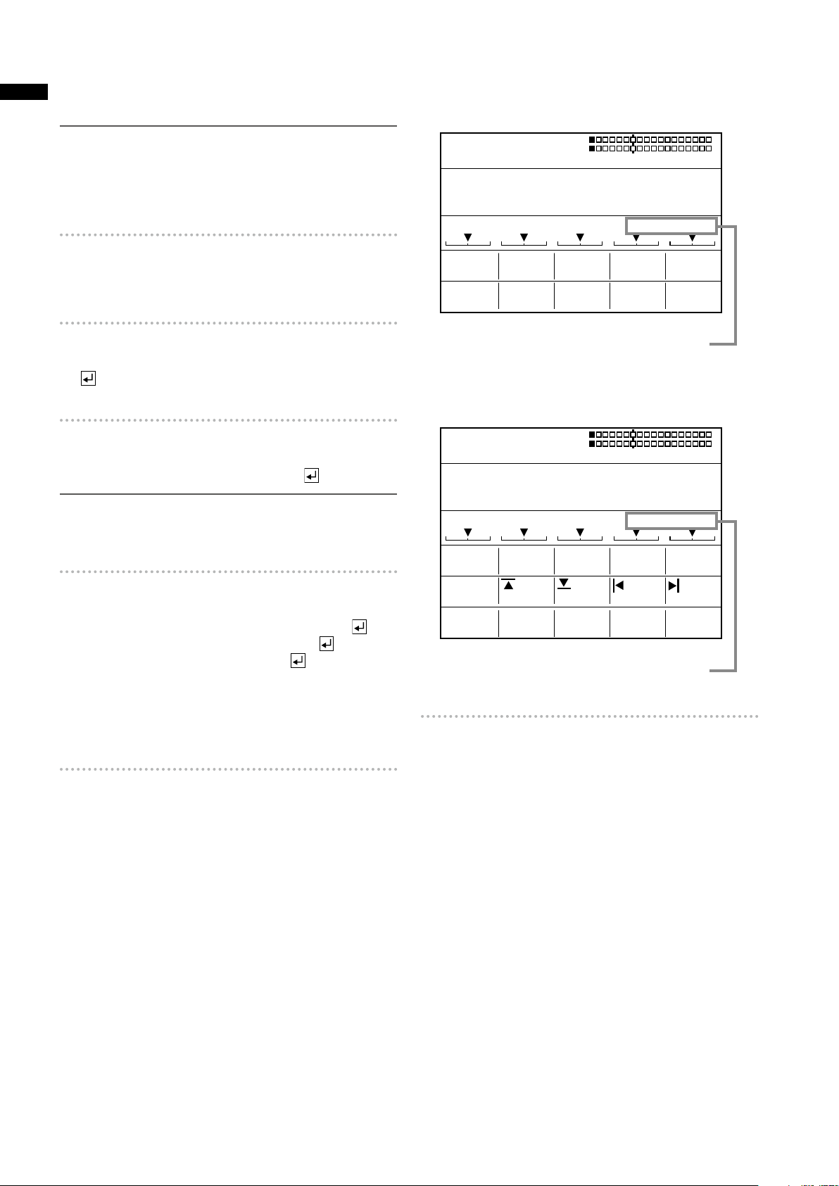
[BASIC PATTERN KEY]/Pattern Key
[PATTERN EDGE]
The items other than [K LEVEL] can be set in the same way
as the transition (wipe) pattern (
page 4).
[PATTERN KEY]
The [BASIC PATTERN KEY] menu or [PATTERN KEY] menu
is used to create a key with key patterns.
The [BASIC PATTERN KEY] menu appears when the
selected pattern has a number in the range of 3001 to
3046, and the [PATTERN KEY] menu appears when the
selected pattern has a number of 3301 or larger.
For pattern numbers, refer to “List of Key Patterns” at the
back of Volume 2.
[BASIC PATTERN KEY] menu
This menu is displayed when the selected pattern has a
number in the range of No. 3001 to No. 3046.
For [K LEVEL], set the key level (transparency level of the
key) in the range of 0 to 255 using the rotary 5 control.
The smaller the setting value, the higher the transparency.
When 0 is set, the key disappears entirely (becomes
transparent).
The key registered in the direct patterns can be individually
set for each pattern.
[CROP] (for [PATTERN KEY] menu only)
Video used as the key can be cropped.
Rotary 1 Rotary 2 Rotary 3 Rotary 4 Rotary 5
Set the top edge of the video in the range of 0 to 243
(480i)/288 (576i)/720 (720P)/540 (1080i) using the rotary 2
control.
The factory default setting is 0.
Set the bottom edge of the video in the range of 0 to 243
(480i)/288 (576i)/720 (720P)/540 (1080i) using the rotary 3
control.
The factory default setting is 0.
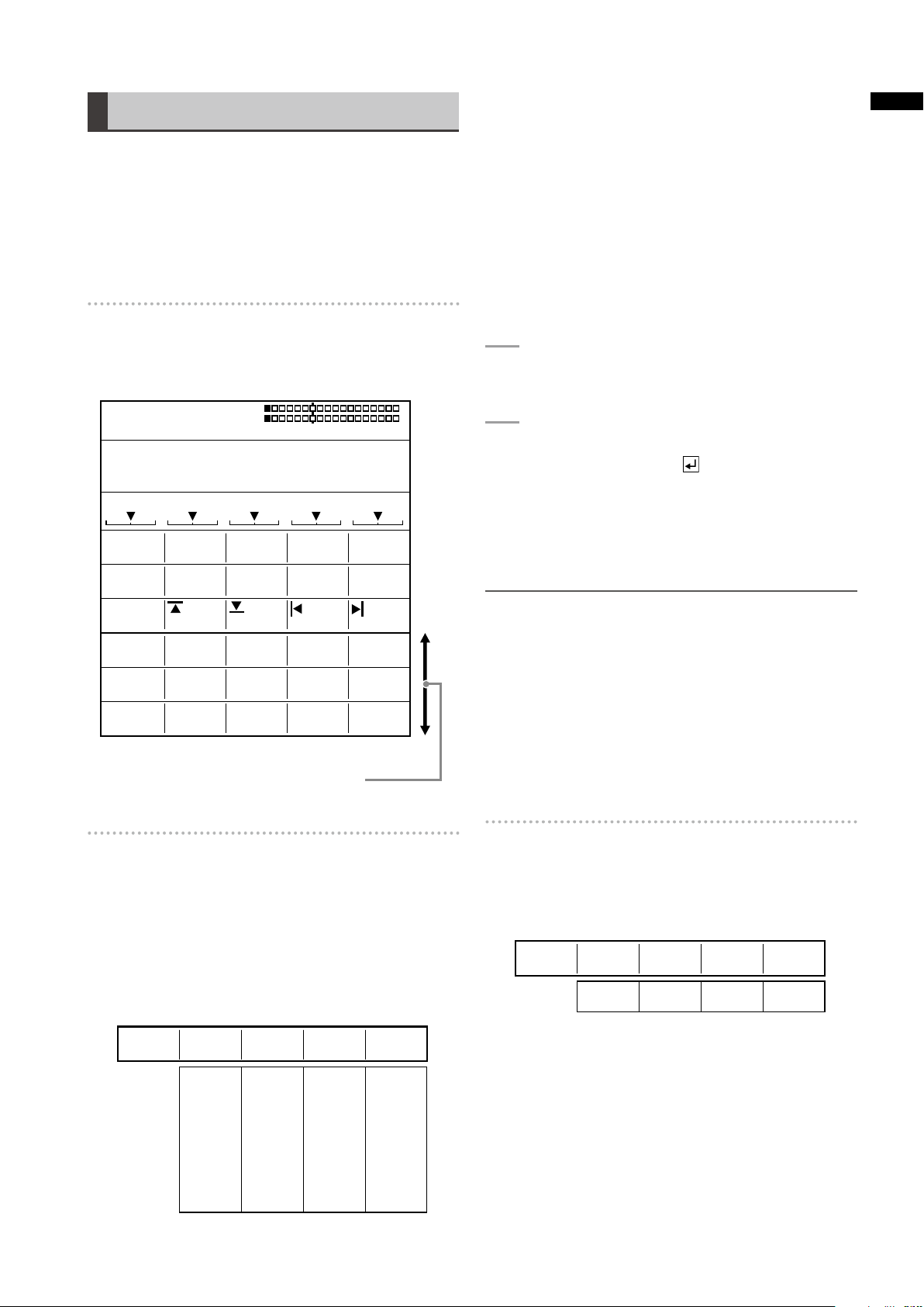
[PATTERN KEY] menu
This menu is displayed when the selected pattern has No.
3301 or larger.
The [PATTERN KEY] menu allows you to make settings for
video cropping.
Scroll the screen to display.
Set the left edge of the video in the range of 0 to 720
(480i/576i)/1280 (720P)/1920 (1080i) using the rotary 4
control.
The factory default setting is 0.
Set the right edge of the video in the range of 0 to 720
(480i/576i)/1280 (720P)/1920 (1080i) using the rotary 5
control.
The factory default setting is 0.
For top and bottom edge settings, when one is increased,
the other may be decreased to prevent the total value of
both settings from exceeding the maximum value.
For right and left edge settings, when one is increased, the
other may be decreased to prevent the total value of both
settings from exceeding the maximum value.
[EFFECTS]
Settings can be made in the same way as in the [EFFECTS]
submenu of the [TRANSITION] menu (
page 4).
[KEY LEARN]
See “Setting Key Learn [KEY LEARN]” ( page 9).
Page 6
6
Chapter 1 Applying Effects to Video and Sound
Setting the Chroma Key
KEY COLOR
OFFSET
COLOR
SLOPE 1 K LEVEL
C-AREA MONO L
1
CANCEL
128
COLOR C SLICE
SLICE 1
0
CROP
EFFECTS
OFF
8 255
3 6
00
BORDER
WHITE
128
128
0
POS.
EVENT
CHROMA KEY 1
ME TIME PATTERN INT
00 E
1:00 F 0062
WHT
X 128
Z 196
Y 128
R=- - - G=- - - B=- - -
1-3 0-255 0-15 0-255
COLORKEY
1
255
K LEVEL
SLICE 1
128
SLOPE 1
8
0-255 0-255 0-3 0-15
OFFSET
COLOR
128
CANCEL 6
MONO L
C SLICE
128
C-AREA
3
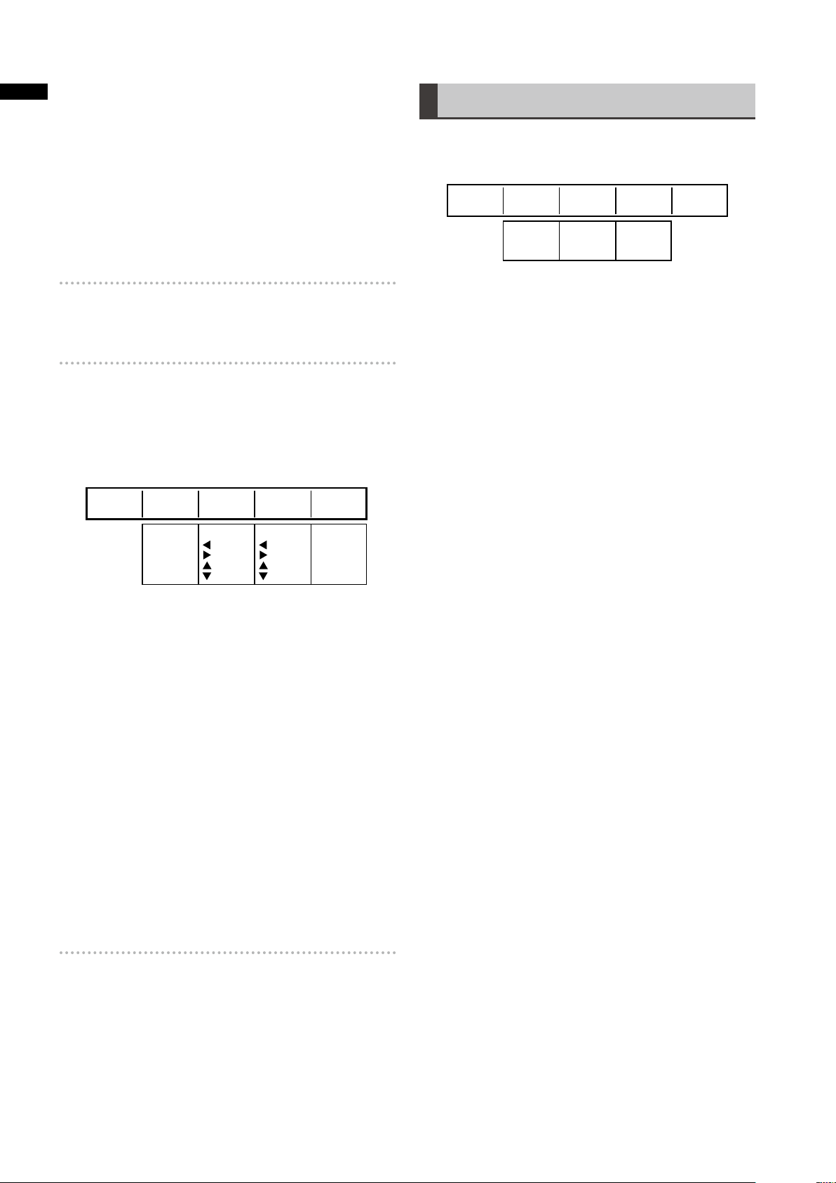
[CHROMA KEY]
Chroma keying is a function for removing a specified color
range from one image and keying another image to the range.
The following diagram shows an example of the chroma
key.
Key is specified
by color on
which the cursor
is placed, and
removed.
The [CHROMA KEY] menu is used to create a chroma key.
[CHROMA KEY] menu
The menu appears when the CHROMA KEY (chroma key)
button is pressed in the PATTERN area (
or the pattern of No. 62 is selected.
ME preview is automatically chosen, and the video to
be keyed with the chroma key cursor is output from the
preview output connector.
Shows the selected number:
1, 2, or 3.
page Vol.1-14)
Shows the selected
color.
[KEY]
Up to three colors to be removed from an image can be
stored.
Rotary 1 Rotary 2 Rotary 3 Rotary 4 Rotary 5
After selecting the number using the rotary 2 control, move
the chroma key cursor on the preview image to the color
(blue for example) to be removed using the joystick, and
press the
The numeric values of the stored color are displayed for R,
G, and B, respectively, in the menu. (“---” appears when the
color is not stored.)
The color can be stored any number of times by pressing
the
it is stored.
To cancel the stored color, enter the selected number using
the numeric keys while holding down the SHIFT key.
To set the chroma key in detail
The color density and range can be specified to designate
more precise keying.
Set [SLICE] of the selected color in the range of 0 to 255
using the rotary 3 control.
The slice is set to specify the color density (saturation) in
the area to be removed. For example, if you specify blue
using the joystick, the setting value can be increased to
remove only blue darker than the specified blue.
key.
key. However, the color data is overwritten each time
Scroll the screen to display.
Set [SLOPE] of the selected color in the range of 0 to 15
using the rotary 4 control.
The slope is set to specify the range (hue) of the color to
be removed. For example, if you specify blue using the
joystick, the setting value can be increased to remove only
blue closest to the specified blue.
Set [K LEVEL] (transparency level of the key) in the range
of 0 to 255 using the rotary 5 control.
NOTE
The value set with the rotary 3 control is saved for each of the
three key colors, while the value set with the rotary 5 control is
applied to all stored colors.
[COLOR CANCEL]
The appearance of color blur can be diminished in the
boundary area of the key.
Rotary 1 Rotary 2 Rotary 3 Rotary 4 Rotary 5
Set [OFFSET] (offset from the key) in the range of [0] to
[255] using the rotary 2 control.
Set [C SLICE] (cancel slice) in the range of [0] to [255]
using the rotary 3 control.
Page 7
7
Chapter 1 Applying Effects to Video and Sound
Set [C-AREA] (cancel area) in the range of [0] to [3] using
POS.
EVENT
LUMINANCE KEY
ME TIME PATTERN INT
00 E
1:00 F 0061
WHT
X 128
Z 196
Y 128
KEY
COLOR
SLOPE K LEVELSLICE
0
CROP
EFFECTS
OFF
15 255
00
BORDER
WHITE
0
0
POS.
EVENT
EXT KEY
ME TIME PATTERN INT
00 E
1:00 F 0059
WHT
X 128
Z 196
Y 128
KEY
COLOR
KEY SLOPE K LEVELSLICE
0
CROP
EFFECTS
OFF
15 255
00
BORDER
WHITE
0SDI1
0
the rotary 4 control.
Set [MONO L] (mono level) in the range of [0] to [15] using
the rotary 5 control.
[CROP]
Settings can be made in the same way as in the [CROP]
submenu of the [PATTERN KEY] menu (
page 5).
Bright area is
removed as key.
[EFFECTS]
Settings can be made in the same way as in the [EFFECTS]
submenu of the [TRANSITION] menu (
page 4).
[BORDER]
Use the rotary 2 control to set [COLOR] (color of the edge)
to one of the colors in the table shown below.
Setting Color
[WHITE] (factory default setting) White
[YELLOW] Yellow
[CYAN] Cyan
[GREEN] Green
[MAGENTA] Magenta
[RED] Red
[BLUE] Blue
[BLACK] Black
[CUSTOM1] or [CUSTOM2] Grey as the factory
default setting
When [CUSTOM1] or [CUSTOM2] is selected, the same
color as set in the [BACK MATTE] submenu of the [INT
VIDEO] menu is applied (
If [TRAIL] is selected in the [EFFECTS] submenu, the color
set in the [BORDER] submenu is used as the border color
when [BODM] or [BODM SPARK] is selected.
page Vol.1-28).
Setting the Luminance Key
[LUMINANCE KEY] /External Key
The [LUMINANCE KEY] menu is used to create a
luminance key.
The [EXT KEY] menu is used to create an external key.
[LUMINANCE KEY] menu
The menu appears when the LUM KEY button is pressed in
the PATTERN area (
61 is selected.
page Vol.1-14) or the pattern of No.
Scroll the screen to display.
[EXT KEY] menu
The menu appears when the EXT KEY button is pressed in
the PATTERN area (
59 is selected.
page Vol.1-14) or the pattern of No.
Luminance keying is a function for creating a key with
the specific brightness (luminance) of one image as the
reference and keying to another image.
External keying is a function for keying a specified
extraneous image. The external keying function enables
keying of an image which is not assigned as the input
source.
The following diagram shows an example of the luminance
key.
[EXT KEY]
Scroll the screen to display.
Page 8
8
Chapter 1 Applying Effects to Video and Sound
[KEY]
POS.
EVENT
TITLE KEY
ME TIME PATTERN INT
00 E
02:00 F 9501
WHT
X 128
Z 512
Y 128
KEY
COLOR
SLOPE K LEVELSLICE
0
CROP
EFFECTS
OFF
15 255
00
BORDER
WHITE
0
0
Set [KEY] (key signal) to one of the following using the
rotary 2 control (for [EXT KEY] menu only).
When the system format is set to HD (
SDI1, SDI2, SDI3, SDI4, HDMI1, HDMI2, DVI-I
When the system format is set to SD (
SDI1, SDI2, SDI3, SDI4, VIDEO1, VIDEO2, DVI-I
The factory default setting is [SDI1] in each case.
To set the luminance key in detail
The color density and luminance level range can be
specified to designate more precise keying.
Set [SLICE] (slice level) in the range of [0] to [255] using
the rotary 3 control.
The factory default setting is [0].
The slice is set to specify the brightness level of the area to
be removed. The setting value can be increased to remove
only the area brighter than the specified area.
Set [SLOPE] in the range of [0] to [15] using the rotary 4
control.
The factory default setting is [15].
The slope is set to specify the luminance level range of the
area to be removed. The setting value can be increased to
remove only the area of the luminance level closest to the
specified level.
Set [K LEVEL] (transparency level of the key) in the range
of [0] to [255] using the rotary 5 control.
The factory default setting is [255].
page Vol.1-19):
page Vol.1-19):
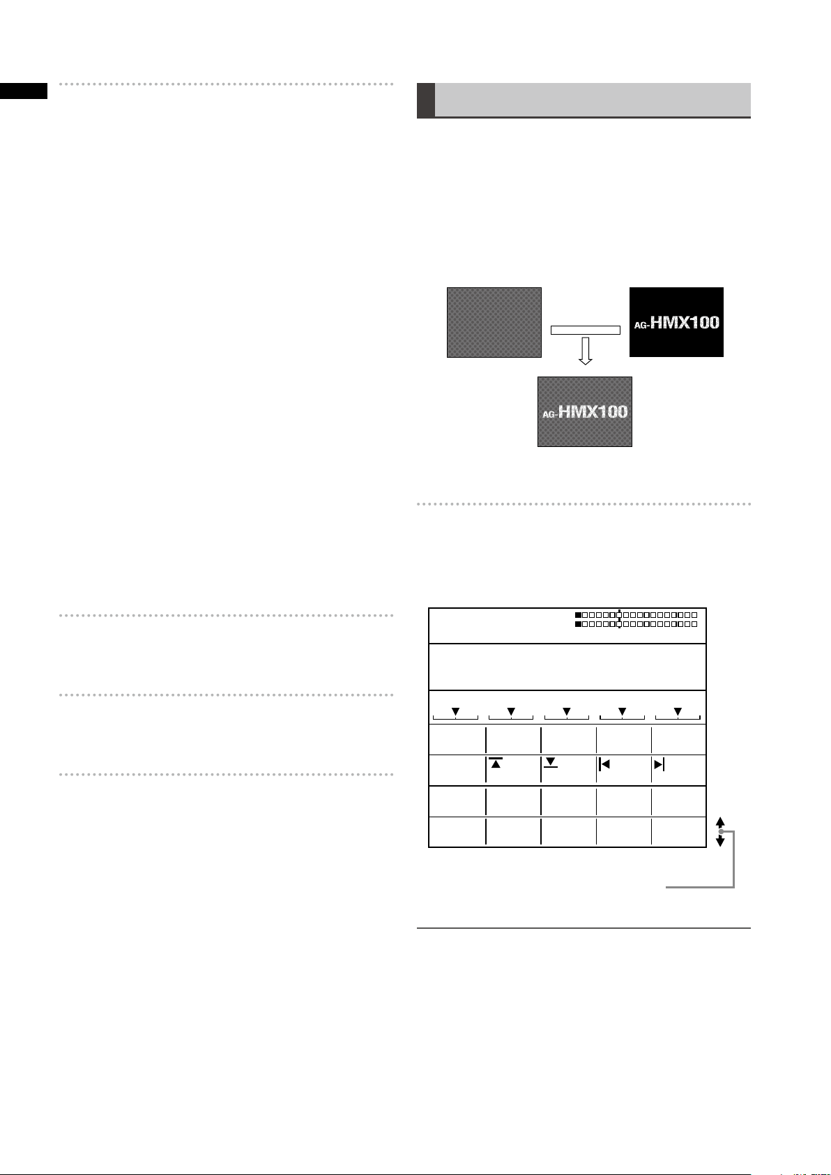
Setting the Title Key [TITLE KEY]
A still picture saved in memory from the [DSK] menu can
be keyed as a title.
Title keys are saved as patterns of the numbers with “1”
as the last digit every 10th (9511, 9521,…) in the range
of 9501 to 9791. (The number of patterns that can be
saved varies with the setting in the [MEMORY] submenu of
[SETUP] menu.)
See “[DSK SOURCE]” for saving title keys (
The following diagram shows an example of the title key.
Back matte video Title
The [TITLE KEY] menu is used to create a title key.
[TITLE KEY] menu
The menu appears when a still picture saved in title
memory is called with the pattern number 9501 or larger
from the [DSK SOURCE] > [MODE] submenu of the [DSK
FADE] menu (
page 11).
page 11).
[CROP]
Settings can be made in the same way as in the [CROP]
submenu of the [PATTERN KEY] menu (
page 5).
[EFFECTS]
Settings can be made in the same way as in the [EFFECTS]
submenu of the [TRANSITION] menu (
page 4).
[BORDER]
Settings can be made in the same way as in the [BORDER]
submenu of the [CHROMA KEY] menu (
page 7).
Scroll the screen to display.
NOTE
The title keys saved in memory are erased when the power •
is turned off. Since memory is empty when the unit is
restarted, the [TITLE KEY] menu is not displayed even if a
pattern number of the title key after No. 9501 is specified.
When a title key is called during execution of the •
downstream key, [DSK EFECTS] (DSK effect) is set to [OFF].
Title keys cannot be set if the title memory count is set •
to 0 in the [MEMORY] submenu of the [SETUP] menu
( page 27).
Page 9
9
Chapter 1 Applying Effects to Video and Sound
[KEY]
9000-9019 SETUP
CLR
ALL CLR
KEY
9000LEARN
EMPTY
SETUP
KEY
K LEVEL
9000
255
LEARN
K FRAME
BASIC
INSERT
REPLACE
CLR KF
COPY
PASTE
EXIT
0
POS.
EVENT ME TIME PATTERN INT
00 E
1:00 F 3001
WHT
X 128
Z 196
Y 128
Settings can be made in the same way as in the [KEY]
submenu of the [LUMINANCE KEY] menu (
page 8).
[CROP]
Settings can be made in the same way as in the [CROP]
submenu of the [PATTERN KEY] menu (
page 5).
[EFFECTS]
Settings can be made in the same way as in the [EFFECTS]
submenu of the [TRANSITION] menu (
page 4).
[BORDER]
Settings can be made in the same way as in the [BORDER]
submenu of the [CHROMA KEY] menu (
page 7).
Setting Key Learn [KEY LEARN]
The key learn function allows storing the key frame
settings (XYZ and key level) in memory and calling them to
reproduce the animation effect.
A key frame refers to a frame which defines changes of the
video used for animation. Several points where a shape
or position of an object is changed can be set in the key
frame to create smooth animation through interpolation
between the points.
With the [(BASIC) PATTERN KEY] menu, the rotary 1 control
can be operated to select [KEY LEARN] to set key learn
in the currently selected key pattern and register the key
pattern as a pattern in the range of No. 9000 to No. 9019.
Rotary 1 Rotary 2 Rotary 3 Rotary 4 Rotary 5
In this case, press the key again to display the Key
Learn Editing screen.
NOTE
When key learn that is already registered in a pattern is edited,
the settings of the original pattern before key learn was set
are given priority. Thus, even if the pattern with key learn set is
called and [SETUP] is selected, no change is given to the base
pattern.
For key learn in a different pattern, it is recommended to use
a pattern number for which EMPTY is displayed or to delete
the existing key learn pattern once and set a new key learn
pattern.
Key Learn Editing screen
To select the key frame number
The key frame number is shown under [K FRAME].
When selecting the key frame number to copy the key
frame or specify a position for inserting the key frame,
select it from the registered key frame numbers using the
rotary 2 control while holding down the SHIFT key.
To select the number applied to the
pattern in which key learn is set
Operate the rotary 2 control to select the pattern number in
the range of 9000 to 9019.
When the number of the pattern with key learn set is
selected, [SAVED] is diplayed. When the number of
the pattern with no key learn set isselected, [EMPTY] is
displayed.
To edit key learn
Select [SETUP] using the rotary 4 control, and press the
key.
The Key Learn Editing screen appears.
When the
selected pattern, the message [OK?] appears.
key is pressed with [SAVED] displayed for the
To set the key frame
Select the editing item including the key position (X, Y,
and Z), aspect, and time using the rotary 1 control, and
proceed with the setting of the key frame. To execute each
editing item, press the
INSERT: Inserts a key frame in the place of the next key
frame.
REPLACE: Replaces the current key frame.
CLR KF: Deletes the current key frame.
COPY: Copies the current key frame.
PASTE: Pastes a copied key frame by overwriting.
EXIT: Cancels the key learn editing mode and saves the
key learn settings.
To set the time up to the current key frame, a value is input
for [ME TIME] with the numeric keys or the TIME rotary
control.
The set time is shown under [ME TIME] on the setting
screen (
Upon completion of registration, select [EXIT] using the
rotary 1 control and press the
settings.
page Vol.1-20).
key.
key to fix the key frame
Page 10
10
Chapter 1 Applying Effects to Video and Sound
The menu returns to the original [(BASIC) PATTERN KEY]
PATTERN COLOR K LEVEL
HARD WHITE 255EDGE 16
WIDTH
POS.
EVENT ME TIME PATTERN INT
00 E
1:00 F 9000
WHT
X 128
Z 196
Y 128
ORIGINAL 3001
BASIC PATTERN KEY
OFF
EFFECTS
PATTERN COLOR K LEVEL
HARD WHITE 255EDGE 16
WIDTH
POS.
0
CROP
EFFECTS
OFF
000
EVENT
PATTERN KEY
ME TIME PATTERN INT
00 E
1:00 F 9001
WHT
X 128
Z 196
Y 128
ORIGINAL 3301
menu.
NOTE
The key position, time, and other items set for the key frames
cannot be changed. To change those items, delete the
applicable key frame and set a new key frame. When inserting
a key frame, be sure to complete the time setting in advance.
To set the transparency level of the key
Set [K LEVEL] in the range of [0] to [255] using the rotary 5
control while holding down the SHIFT key.
[BASIC PATTERN KEY] menu (original pattern
No. 3001 to No. 3046)
To make settings for other key pattern
By using the rotary 1 control to select [EXIT] and pressing
the
key, cancel the key learn editing mode, select the
key pattern, and display the key learn editing screen again.
To preview the operation of the key
Select the pattern with [SAVED] indicated, use the rotary 4
control to select [PREVIEW], and press the
NOTE
[PREVIEW] is displayed only when settings have been made in
the menu for the same pattern as that with key learn set.
key
To delete a key learn pattern
Select the pattern with [SAVED] indicated, use the rotary 4
control to select [CLR] or [ALL CLR], and press the key.
When the message [OK?] appears, press the
To cancel the pattern deletion, press the
holding down the SHIFT key.
When [CLR] is selected, the currently selected key learn
pattern is deleted. When [ALL CLR] is selected, all key
learn patterns are deleted.
key again.
key while
To use a pattern with key learn set
Key learn is set in the patterns in the range of No. 9000 to
No. 9019.
Original pattern number
[PATTERN KEY] menu (original pattern No.
3301 or larger)
Original pattern number
To execute key learn
Set the items in the [(BASIC) PATTERN KEY] menu, and
press the AUTO TAKE button.
When one of those patterns is selected, [(BASIC) PATTERN
KEY] menu for No. 9000 to No. 9019 patterns appears.
([KEY LEARN] is not displayed as the setting item.)
If key learn is set in the selected pattern in the range of
No. 3001 to No. 3046, the [BASIC PATTERN KEY] menu
appears. If key learn is set in the selected pattern of No.
3301 or larger, the [PATTERN KEY] menu appears.
Page 11
Setting the Downstream Key (DSK)
POS.
DSK KEY
SLICE
TO
PAGE MODE
REVERSE
K LEVEL
SDI1
KEY
ON/OFF
SOURCE
0
DSK SLOPE
FILE
0
CROP
DSK
OFF
1 WRITE
OFF 255
00
FADE
BLACK
SDI1
8
PHONE
EFFECTS
DSK
AUDIO
AFTERON
OFF
ME TRIG SLIDE O. SPEEDSLIDE I.
OFF 8OFF
0
EVENT
DSK FADE
ME TIME PATTERN INT
00 E
2:00 F 9501
WHT
X 128
Z 512
Y 128
SDI1
SDI2
SDI3
SDI4
HDMI1
HDMI2
VIDEO1
VIDEO2
DVI-I
TITLE
BODMAT
WRITE
VIEW
1-30
(480i/59i)
1-30
(576i/50i)
1-14 (720p)
1-6 (1080i)
SDI1
SDI2
SDI3
SDI4
HDMI1
HDMI2
VIDEO1
VIDEO2
DVI-I
TITLE
DSK
SDI1
KEY
SDI1
FILL
1
PAGE
WRITE
MODE
SOURCE
0-15 0-255OFF
ON
0-255
DSK
0
SLICE8SLOPE
OFF
REVERSE
255
K LEVEL
KEY
A downstream key refers to a key which is mixed at the end
of the effects including transition and keying. A key that you
want to display in the foreground of an image is set as a
downstream key.
The set downstream key can be saved as a title key in
memory.
The [DSK FADE] menu is used to insert the downstream
key.
[DSK FADE] menu
This menu appears when the DSK FADE button is pressed
or the DSK selector button is pressed for preview of the
downstream key.
To select the key video
Use the rotary 2 control.
The choices are [SDI1] to [SDI4], [HDMI1], [HDMI2],
[VIDEO1], [VIDEO2], [DVI-I], and [TITLE] (still picture
saved in title memory).
To select the key fill video
Use the rotary 3 control.
[BODMAT] (border matte) can also be selected as well as
[SDI1] to [SDI4], [HDMI1], [HDMI2], [VIDEO1], [VIDEO2],
[DVI-I], and [TITLE] (still picture saved in title memory).
To save DSK as a title key
Use the rotary 4 control to select the page
1
number of memory where the title is saved.
Set [MODE] to [WRITE] using the rotary 5
2
control, and press the key.
The title is saved on the selected page.
However, if the preceding page of the selected
page is unsaved (EMPTY), the preceding page, the
selected page and the following pages can be used
for saving the title.
Chapter 1 Applying Effects to Video and Sound
[DSK SOURCE]
[KEY] and [FILL] can be set.
A key is material used as the downstream key, while a fill is
video to be inserted to the material selected as the key.
For example, characters such as a text or material in the
shape of a pattern are created on the background of a
color and specified as the key. Other video can be inserted
as the fill to the key.
Rotary 1 Rotary 2 Rotary 3 Rotary 4 Rotary 5
Scroll the screen to display.
NOTE
Title keys cannot be set if the title memory count is set •
to 0 in the [MEMORY] submenu of the [SETUP] menu
( page 27).
Upon save of a title, set [MODE] to [VIEW] to prevent the •
saved title from being overwritten.
All of the saved titles are erased when the power is turned •
off.
If [KEY] and [FILL] are set during title key creation with a •
title or the star or heart pattern selected, the key fill settings
are changed to a title using the MIX (56) pattern. (The
selected title, star, or heart pattern is canceled.)
[DSK KEY]
For the video for the downstream key selected in the
[DSK SOURCE] submenu, it is possible to change the
transparency level and select whether to reverse the video.
Rotary 1 Rotary 2 Rotary 3 Rotary 4 Rotary 5
Set [SLICE] (slice level) in the range of [0] to [255] using
the rotary 2 control.
The factory default setting is [0].
The slice is set to specify the brightness level of the area to
be removed. The setting value can be increased to remove
only the area brighter than the specified area.
Set [SLOPE] in the range of [0] to [15] using the rotary 3
control.
The factory default setting is [0].
11
Page 12
The slope is set to specify the luminance level range of the
OFF 2-64OFFOFF
ON
DSK
OFF
ME TRIG
OFF
SLIDE I.
OFF
SLIDE O.8SPEED
ON/OFF
BLACK
WHITE
BLUE
AFTER
PRE
ON
OFF
FADE
BLACK
TO
ON
AUDIO
AFTER
PHONE
area to be removed. The setting value can be increased to
Chapter 1 Applying Effects to Video and Sound
remove only the area of the luminance level closest to the
specified level.
Set [REVERSE] (reversing the key signal) to [ON] or [OFF]
using the rotary 4 control.
The factory default setting is [OFF].
Set [K LEVEL] (transparency level of the key) in the range
of [0] to [255] using the rotary 5 control.
The factory default setting is [255].
Setting the Fade [FADE]
The [DSK FADE] menu is used to set the fade effect
(
page 11).
Rotary 1 Rotary 2 Rotary 3 Rotary 4 Rotary 5
[CROP]
Settings can be made in the same way as in the [CROP]
submenu of the [PATTERN KEY] menu (
page 5).
DSK slide on/off [DSK ON/OFF]
The direction and time of the slide in/out operation can be
set for executing the downstream key.
[SLIDE I.] and [SLIDE O.] are effective if [KEY] is set to
[TITLE] in the [DSK SOURCE] submenu.
Rotary 1 Rotary 2 Rotary 3 Rotary 4 Rotary 5
Operate the rotary 2 control to set whether or not to
execute downstream key additionally during auto transition
executed with the AUTO TAKE button.
The factory default setting is [OFF].
Operate the rotary 3 control to set the direction of the slide
in operation when DSK is ON.
The factory default setting is [OFF].
Select the video color after fading from [BLACK], [WHITE],
and [BLUE] using the rotary 2 control.
The factory default setting is [BLACK].
Set [AUDIO] (sound fading) to [ON] or [OFF] using the
rotary 3 control.
The factory default setting is [ON].
Set [PHONE] (fading of headphones output) to [AFTER] or
[PRE] using the rotary 4 control. [AFTER] generates sound
with fade applied, while [PRE] generates sound without
fade.
The factory default setting is [AFTER].
Operate the rotary 4 control to set the direction of the slide
out operation when DSK is ON.
w: Sliding toward the left
q: Sliding toward the right
e: Sliding toward the top
r: Sliding toward the bottom
The factory default setting is [OFF].
Operate the rotary 5 control to set the sliding speed.
Select an even number in the range of [2] to [64].
The factory default setting is [8].
[DSK EFFECTS]
Settings can be made in the same way as in the [EFFECTS]
submenu of the [TRANSITION] menu (
12
page 4).
Page 13

13
Chapter 1 Applying Effects to Video and Sound
COLOR
0 0 128 128 0
Y SETUP Y GAIN P
B PR C GAIN
EVENT ME TIME PATTERN INT
00 E
1:00 F 3001
BLUE
PB 128
C GAIN 0
PR 128
COLOR EFFECTS
CH A
Adjusting Input Video
Adjusting Colors of Video [COLOR EFFECTS]
The [COLOR EFFECTS] menu is used to make settings for
applying effects to the colors of video for each bus.
The color effects to video can be set including color
balance and brightness adjustment.
NOTE
The color effect and MONO (monochrome) effect cannot be
used at the same time. The color effect cannot be applied to
the video to which MONO has been applied as the video effect.
[COLOR EFFECTS] menu
The menu appears when the A/PROG COLOR EFFECTS or
B/PRESET COLOR EFFECTS button is pressed to turn on.
The color effects set currently are applied at the same time.
To display the menu without applying the effects, press
either COLOR EFFECTS button while holding down the
SHIFT key.
When the preview output is executed, switching is
automatically performed between video A and video B
according to the pressed button.
To set the color saturation to 0 temporarily
Press the CENTER button during operation of the [COLOR
EFFECTS] menu, the color saturation can be set to zero
temporarily.
NOTE
If the No. 221 or 222 (1068 or 1069) pattern is selected, the •
MIX pattern with the color effects applied is set, the COLOR
EFFECT button is lighted, and the [COLOR EFFECTS] menu
appears.
No color effects can be applied to internal video. •
Applying Effects to Video [VIDEO EFFECTS]
The [VIDEO EFFECTS] menu is used to apply changes to
video or video switching effect for each bus.
Special video effects such as mosaic and paint can be set
in this menu.
NOTE
No video effects can be applied to internal video.•
Only one choice can be made from multi-strobe, decay, trail, •
and shadow. The effect selected last has priority, and the
previously selected effect is canceled.
Decay cannot be set to ON for both A/PROG and B/PRESET •
at the same time. The setting made last has priority and the
other made earlier is turned OFF.
Only one choice can be made from multi-strobe and mosaic. •
The effect selected last has priority, and the previously
selected effect is canceled.
Set [Y SETUP] (Y signal setup) in the range of [–128] to
[+127] using the rotary 1 control.
The factory default setting is [0].
Set [Y GAIN] (Y signal gain) in the range of [–128] to
[+127] using the rotary 2 control (0 dB=0).
The factory default setting is [0].
To adjust the color balance, adjust [PB] and [PR]. Use
the rotary 3 (for X direction) and rotary 4 (for Y direction)
controls or operate the joystick in the X and Y directions.
Set [C GAIN] (chroma gain) using the rotary 5 control or
rotary Z control.
At that time, the joystick, rotary Z control settings, and 3D
display area of the setting screen (
the PB, PR, and C GAIN values.
[VIDEO EFFECTS] menu
The menu appears when the A/PROG VIDEO EFFECTS
or B/PRESET VIDEO EFFECTS button is pressed to turn
on. The video effects set currently are applied at the same
time.
To display the menu without applying the effects, press
either VIDEO EFFECTS button while holding down the
SHIFT key.
When the preview output is executed, switching is
automatically performed between video A and video B
according to the pressed button.
page Vol.1-20) shows
Page 14

14
Chapter 1 Applying Effects to Video and Sound
POS.
MOSAIC
Y
H
SIZE
OFF
EFFECTS
OFF
DEFOCUS LEVEL
OFF
MONO
TIME
OFF
8
16
4
DECAY TIME
LEVEL
C
PAINT
NEGA
OFF
OFF
OFF
OFF
OFF OFF
MIRROR V
XY
2
EVENT
VIDEO EFFECTS
CH A
ME TIME PATTERN INT
00 E
01:00 F 3001
WHT
X 128
Z 196
Y 128
OFF
ON
XY
X
Y
0-31
MOSAIC
OFF
SIZE
XY 0
OFF
ON
0-7
DEFOCUS
OFF
LEVEL
0
OFF
ON
MONO
OFF
[DEFOCUS]
The video effect of purposely displacing the focus can be
set to perform fantastical rendering or get the attention of
viewers.
The following diagram shows an example of the defocus
effect.
Scroll the screen to display.
[MOSAIC]
The mosaic effect can be applied to input video.
The following diagram shows an example of the mosaic
effect.
Mosaic effect
Rotary 1 Rotary 2 Rotary 3 Rotary 4 Rotary 5
Rotary 1 Rotary 2 Rotary 3 Rotary 4 Rotary 5
Select [ON] or [OFF] to specify whether or not to apply the
effect using the rotary 2 control.
The factory default setting is [OFF].
Set [LEVEL] in the range of 0 to 7 using the rotary 3 control.
The factory default setting is 2.
This level setting is applied to No. 1004 (203) transition
pattern. This effect cannot be activated with any twodimensionally compressed pattern at the same time.
Defocus effect
NOTE
Either mosaic or defocus can be selected. Whichever is
selected later has priority and the other selected earlier is
canceled.
[MONO]
Chroma (color) can be deleted to generate monochrome
video.
Rotary 1 Rotary 2 Rotary 3 Rotary 4 Rotary 5
Select [ON] or [OFF] to specify whether or not to apply the
effect using the rotary 2 control.
The factory default setting is [OFF].
Set the direction of applying the mosaic effect to [XY]
(horizontal and vertical), [X] (horizontal only), or [Y] (vertical
only) using the rotary 3 control.
Set [SIZE] in the range of 0 to 31 using the rotary 4 control.
The factory default setting is 8.
This size setting is applied to Nos. 1001, 1002, and 1003
(200, 201, and 202) patterns.
Select [ON] or [OFF] to specify whether or not to apply the
effect using the rotary 2 control.
The factory default setting is [OFF].
This setting has a priority over the settings made in the
[COLOR EFFECTS] menu (
page 13).
Page 15

15
Chapter 1 Applying Effects to Video and Sound
[TIME EFFECTS]
OFF
STILL
STROBE
FIELD
FRAME1@ 4
@ 9
@ 16
R 4
R 9
R 16
MANUAL
2-124
TIME
OFF
EFFECTS 2
SCREEN
FLEID
TIME
1
FIELD
FRAME
TIME
STILL
EFFECTS FIELD
FIELD
FRAME1@ 4
@ 9
@ 16
R 4
R 9
R 16
MANUAL
2-124
TIME
STROBE
EFFECTS 2
SCREEN
FIELD
TIME
1
The still, strobe, or multi-strobe effect can be set.
Still: Keeps the video still.
Strobe: Plays video frame by frame.
Multi-strobe: Divides the screen into 4, 9, or 16 screens
and displays the strobe image on each divided screen.
The following diagram shows an example of the multistrobe effect.
Multi-strobe effect (16 screens)
The still effect can be executed by pressing the A/PROG
bus (or B/PRESET bus) STILL button.
The strobe effect can be executed by pressing the A/PROG
bus (or B/PRESET bus) STROBE button.
When the STILL or STROBE button is pressed to turn on,
the [VIDEO EFFECTS] menu appears (
NOTE
When the STILL or STROBE button is pressed to execute the
effect, the video effects set in the VIDEO EFFECTS menu are
also executed at the same time.
Rotary 1 Rotary 2 Rotary 3 Rotary 4 Rotary 5
page 13).
If [STROBE] is selected
Rotary 1 Rotary 2 Rotary 3 Rotary 4 Rotary 5
Select [FIELD] or [FRAME] using the rotary 3 control.
The factory default setting is [FIELD].
Set [SCREEN] (number of strobe screens) and the repeat
count using the rotary 4 control.
The factory default setting is 1.
A numeric value such as [@ 4] is set to specify the number
of screens into which the screen is divided for strobe image
display.
When @ is given to a numeric value: The strobe image
is sequentially displayed only once on each of the
screens divided according to the value.
When R is given: It is repeated to sequentially display the
strobe image on each of the screens divided according
to the value.
Set [TIME] (strobe duration) in the range of [2] to [124]
using the rotary 5 control.
Time can be changed in 2 steps.
The factory default setting is [20].
Select [STILL] or [STROBE] using the rotary 2 control.
Select [OFF] to apply no effect.
When [OFF] is selected, both the STILL and STROBE
execution buttons are also set to off (turned off).
If [STILL] is selected
Rotary 1 Rotary 2 Rotary 3 Rotary 4 Rotary 5
Select [FIELD] or [FRAME] using the rotary 3 control.
The factory default setting is [FIELD].
When [TIME] is set to [MANUAL], the screen can be
stopped by pressing the A/PROG bus STROBE button or B/
PRESET bus STROBE button while holding down the SHIFT
key.
This time setting is applied to Nos. 1062, 1063, 1064, and
1065 (215, 216, 217, and 218) transition patterns.
NOTE
When any of the following patterns is selected, only one •
choice can be made from SOFT, BORDER, and SOFT
BORDER for multi-strobe and pattern edge. The effect
selected last has priority, and the previously selected effect
is canceled.
Nos. 1541 to 1550 (32 to 35, 130 to 133, and 141 to 142)
Nos. 3304, 3314, and 3324
Either strobe or still can be selected. Whichever is selected •
later has priority and the other selected earlier is canceled.
Either multi-strobe or scene grabber can be selected. •
Whichever is selected later has priority and the other
selected earlier is canceled.
The multi-strobe effect cannot be enabled for both A/PROG •
and B/PRESET at the same time. The setting made last has
priority and the other made earlier is disabled.
When the still or strobe (including multi-strobe) effect is •
activated, selecting a two-dimensionally compressed pattern
cancels the still or strobe effect. When a two-dimensionally
compressed pattern is selected, applying the still or strobe
effect changes the pattern being used to the MIX(56) pattern.
Page 16

16
Chapter 1 Applying Effects to Video and Sound
[DECAY]
OFF
ON
0-32
DECAY
OFF
TIME
16
OFF
ON
0-7
PAINT
OFF
LEVEL
4
OFF
ON
OFF
ON
NEGA
OFF
CY
OFF
OFF
ON
OFF
ON
MIRROR
OFF
VH
OFF
The afterimage effect can be added to video.
[NEGA]
The brightness of video can be inverted.
The following diagram shows an example of the decay
effect.
Decay effect
Rotary 1 Rotary 2 Rotary 3 Rotary 4 Rotary 5
Select [ON] or [OFF] to specify whether or not to apply the
effect using the rotary 2 control.
The factory default setting is [OFF].
Set [TIME] in the range of [0] to [32] using the rotary 3
control.
The factory default setting is [16].
This time setting is applied to No. 1066 (219) pattern.
NOTE
The decay effect cannot be applied to both input source video
A and B at the same time. When the decay effect is enabled for
one video, it is automatically disabled for the other video.
The following diagram shows an example of the negative
effect.
Negative effect
Rotary 1 Rotary 2 Rotary 3 Rotary 4 Rotary 5
Select [ON] or [OFF] to specify whether or not to apply the
Y signal negative setting [Y] using the rotary 2 control and
the chroma signal negative setting [C] using the rotary 3
control, respectively.
The factory default setting is [OFF] for both items.
[MIRROR]
The mirror effect can be produced in the horizontal or
vertical directions.
The following diagram shows an example of the mirror
effect.
[PAINT]
The image tone can be decreased to generate painting-like
video.
The following diagram shows an example of the paint
effect.
Paint effect
Rotary 1 Rotary 2 Rotary 3 Rotary 4 Rotary 5
Select [ON] or [OFF] to specify whether or not to apply the
effect using the rotary 2 control.
The factory default setting is [OFF].
Set [LEVEL] in the range of 0 to 7 using the rotary 3 control.
The factory default setting is 4.
This level setting is applied to No. 1034 (211) transition
pattern.
Horizontal direction
Vertical direction
Horizontal and
vertical directions
Mirror effect
Rotary 1 Rotary 2 Rotary 3 Rotary 4 Rotary 5
Select [ON] or [OFF] to specify whether or not to apply the
mirror setting in the horizontal direction [H] using the rotary
2 control and in the vertical direction [V] using the rotary 3
control, respectively.
The factory default setting is [OFF] for both items.
Page 17

17
Chapter 1 Applying Effects to Video and Sound
Setting Audio Effects
POS.
PAN IN CH
BALANCE
OFF L
EQ
EQ
1
ON
L LEVEL
0
0
0
0.5
H LEVEL
Q
MID
M LEVEL0FREQ
VOICE LEVELPITCH
1.01kHZ
5OFF UP
OFF AB
CHANGE
MUTE
EVENT
AUDIO EFFECTS
ME TIME PATTERN INT
00 E
02:00 F 0056
WHT
X 128
Z 512
Y 128
1 - 8
AUX
OFF
ON
L
R
L+R
L7
L6
L1
0
R1
R2
R7
PAN
OFF L
IN CH0BALANCE
OFF
ON
–14dB - 14dB –14dB - 14dB
EQ
ON 0
L LEVEL0H LEVEL
–14dB - 14dB
0.5
1
2
5
100Hz-10.2kHz
MID
EQ
0
M LEVEL
1.01kHz
FREQ
0.5
Q
The [AUDIO EFFECTS] menu is used to process sound.
Audio effects can be set for each input source.
To execute the audio effects
Press the AUDIO EFFECTS execution button.
The AUDIO FOLLOW VIDEO button can be pressed to turn
on to link the video effects and the audio effects during
execution of transition or fade.
[AUDIO EFFECTS] Menu
The menu appears when the AUDIO EFFECTS button is
pressed.
Set [IN.CH] to [L], [R], or [L+R] using the rotary 4 control.
[IN.CH] is used to select the channel to be emphasized.
L: Left channel
R: Right channel
L+R: Both left and right channels
The factory default setting is [L].
Set [BALANCE] in the range of L7 to 0 and 0 to R7 using
the rotary 5 control.
[BALANCE] is used to select whether to expose the
channel selected with [IN.CH] toward the right direction
(R) or left direction (L) and to set the gap from the center
position using a numeric value.
The factory default setting is 0 (center).
[EQ]
[EQ MID] is used to adjust the high-range or mid-range
audio level and set equalizer effects.
Rotary 2 Rotary 3 Rotary 4 Rotary 5
Scroll the screen to display.
Select the input source using the rotary 1 control.
[1] to [8]: Input sources 1 to 8
[AUX]: AUX input
Select the effect to set using the rotary 2 control.
[PAN]
[PAN] is set to change the audio balance between left and
right.
Select [ON] or [OFF] to specify whether or not to apply the
effect using the rotary 3 control.
The factory default setting is [OFF].
Rotary 2 Rotary 3 Rotary 4 Rotary 5
Select [ON] or [OFF] to specify whether or not to apply all
equalizer effects using the rotary 3 control.
The factory default setting is [ON].
Set the [L LEVEL] (low-range level in dB) in the range of
[–14dB] to [14dB] in 2 dB steps using the rotary 4 control.
The factory default setting is [0].
Set the [H LEVEL] (high-range level in dB) in the range of
[–14dB] to [14dB] in 2 dB steps using the rotary 5 control.
The factory default setting is [0].
[EQ MID]
Rotary 2 Rotary 3 Rotary 4 Rotary 5
Set the [M LEVEL] (mid-range level in dB) in the range of
[–14dB] to [14dB] in 2 dB steps using the rotary 3 control.
The factory default setting is [0].
Set the [FREQ] (Frequency to be emphasized) in the range
of [100Hz] to [10.2kHz] using the rotary 4 control.
The factory default setting is [1.01kHz].
Page 18

Set [Q] (Quality factor value: resonance level) to [0.5], [1],
OFF
ON
DOWNUP0-10
CHANGE
VOICE
OFF
UP
PITCH5LEVEL
OFF AB
OFF
-12dB
-20dB
-60dB
AB
ABAUX
ALL
MUTE
[2] or [5] using the rotary 5 control. As the value is larger,
Chapter 1 Applying Effects to Video and Sound
resonance lasts longer.
The factory default setting is [0.5].
[VOICE]
Settings can be made for the voice changer.
Rotary 2 Rotary 3 Rotary 4 Rotary 5
Select [ON] or [OFF] to specify whether or not to apply the
effect using the rotary 3 control.
The factory default setting is [OFF].
Select [UP] or [DOWN] for [PITCH] to specify whether to
increase or decrease the sound pitch using the rotary 4
control.
The factory default setting is [UP].
Set [LEVEL] in the range of 0 to 10 using the rotary 5
control.
The factory default setting is 5.
[MUTE]
Rotary 1 Rotary 2 Rotary 3 Rotary 4 Rotary 5
Select the mute level from [–12dB], [–20dB], and [–60dB]
using the rotary 3 control.
Select [OFF] to apply no effect.
The factory default setting is [OFF].
Select the channel to mute from [AB] (buses A and B),
[ABAUX] (buses A and B and AUX output), and [ALL] (all
channels) using the rotary 4 control.
The factory default setting is [ALL].
18
Page 19

19
Chapter 2 Registering Settings and Effects
1-8 SAVE
RECALL
ALL CLR
EMPTYFILE
1
SAVE
Chapter 2 Registering Settings and Effects
If the menu settings and created effects are stored in internal memory, the same settings and effects can be quickly
reproduced.
The settings made on the setting screen (
with numbers allocated can be registered in memory (event memory).
The settings of the [SETUP] menu (
page Vol.1-20) are referred to as “events” on this unit, where up to 100 events
page Vol.1-22) can be registered in up to eight files.
File operation [FILE]
In the [FILE] submenu of the [SETUP] menu, it is possible
to save the settings of the [SETUP] menu in a file and call
the file using the rotary 2 and 3 controls.
The following types of data are saved and called.
[SETUP] menu setting values•
[AUDIO/VIDEO] input settings•
X, Y, and Z position settings (individual settings for direct •
patterns and common settings for other patterns)
Registration contents of direct patterns•
Rotary 1 Rotary 2 Rotary 3 Rotary 4 Rotary 5
To clear a saved file
Select [ALL CLR] using the rotary 3 control.
When the message [OK?] appears, press the key.
To cancel the file clear, press the key while holding
down the SHIFT key.
To select a file to operate
Select the file number from [1] to [8] using the rotary 2
control.
When the file of the selected number is null, [EMPTY] is
shown. When the file is already saved, [SAVED] is shown.
To save the current settings in a file
Select [SAVE] using the rotary 3 control.
When the message [OK?] appears, press the
To cancel the file save, press the
down the SHIFT key.
key while holding
key.
To call a saved file
Select [RECALL] using the rotary 3 control.
When the message [OK?] appears, press the
The file of the selected number is called and the settings of
the [SETUP] menu are changed to those saved in the file.
NOTE
If an empty file is selected ([EMPTY] is displayed), [RECALL] •
is not displayed.
When the unit must be restarted due to the system format •
change caused by data call, the message “TURN POWER
OFF” appears. In this case, turn off the power and restart the
unit.
key.
Page 20

20
Chapter 2 Registering Settings and Effects
EVENT
00E
Event Memory Operation
The EVENT SET and EVENT RECALL buttons are used to
register and call events, respectively.
The currently selected event number is shown in the event
number display area of the setting screen. [E] is shown for
a null event.
Registering the Current Settings and Created Effects as Events
Press the EVENT SET button.
1
The button is lighted.
Select the event number in the range of 0 to 99.
2
Enter the number using the numeric keys or
increment or decrement the value using the +
or – key, respectively.
To call the settings, press the key.
3
The EVENT RECALL button goes off.
The selected event is called and the settings of the
setting screen are changed to those registered as
the event.
Press the AUTO TAKE button.
4
The effects registered as the event are executed.
If one of the events in which a series of
effects were registered is called
If 10 events are consecutively registered with event
numbers in the range of 50 to 59, 60 to 69, 70 to 79,
80 to 89, or 90 to 99, the settings of the first event are
reproduced when one of the 10 events is called.
NOTE
When the event is called, the settings of the input source used
during creation of the effects are not reproduced. The effects
are executed with the currently available input source settings.
Thus, first reproduce the same input source settings as those
during effect creation, and then call the event to execute.
Press the key.
3
The EVENT SET button flashes for approximately 2
seconds, and then goes off.
To register a series of effects as events
Up to 10 effects can be consecutively registered as events
with numbers 50 to 59, 60 to 69, 70 to 79, 80 to 89, or 90 to
99.
Since those 10 events can be called and executed
consecutively, the key frame settings can also be
registered as events.
Calling Events
Press the EVENT RECALL button.
1
The button is lighted.
Select the event number. Enter the number
2
using the numeric keys or increment or
decrement the value using the + or – key,
respectively.
Clearing Event Memory
Press the EVENT RECALL button.
1
The button is lighted.
Select the event number. Enter the number
2
using the numeric keys or increment or
decrement the value using the + or – key,
respectively.
Press the key while holding down the SHIFT
3
key.
The EVENT RECALL button goes off.
The memory of the selected event is cleared.
Page 21

Clearing All the Event Memory
Press the EVENT RECALL button.
1
The button is lighted.
Press the . (period) key twice.
2
“**” is displayed instead of an event number.
Press the key while holding down the SHIFT
3
key.
Chapter 2 Registering Settings and Effects
21
Page 22

22
Chapter 3 Switching 3D Video
Chapter 3 Switching 3D Video
L
R
SDI IN 1
L
R
L
R
SDI IN 2
SDI IN 3
SDI IN 4
SDI OUT MULTI VIEW
ADV-REF
DVI-D OUT PGM
DVI-D OUT
MULTI VIEW
SDI OUT PGM
When two different types of video for the left eye (L channel) and right eye (R channel) are monitored in the overlay state,
adjustment is made for allowing the left eye and right eye to view the L-channel video and R-channel video, respectively,
for example, wearing 3D glasses. This adjustment enables the brain to recognize the images on video as stereoscopic
images.
When the parallax (distance between left and right eyes) is virtually increased, a 3D appearance and a sense of depth are
enhanced.
When 3D video is used as the input source to this unit, two input connectors are paired to input one video for the left eye
and the other for the right eye.
Example Connections with 3D Camera
This section shows examples of systems in which this unit
and 3D camera are connected to create 3D video using
each input video for the L and R channels.
The following are three system examples:
System for displaying the program output and multi-view •
output of this unit on a single monitor (simultaneous
display of L and R channels)
System for individually displaying the program output •
and multi-view output on different monitors (use of SIDE
BY SIDE signal)
System for using video from four cameras as the input •
sources to two units of AG-HMX100P/HMX100E
NOTE
The 3D video production systems shown below cannot •
perform preview output. AUX output can be used only for
input source check. Of the video switching effects, only cut
can be executed.
When [3DFORMAT] is set to [1080/23PsF] in 3D mode, •
this unit cannot be synchronized with an external signal
generator.
System for Monitoring Program Output as L channel and Multi-view Output as R Channel (Simultaneous Display of L and R Channels)
SDI input 1 and SDI input 2 are paired to be used as
L-channel and R-channel input sources, respectively.
SDI input 3 and SDI input 4 are paired to be used as
L-channel and R-channel input sources, respectively.
Advanced reference signal*
1
Program output and multi-view output are paired to be
used as L-channel and R-channel outputs.
3D mode is set to [MODE1] (
page 25).
SDI (video and
audio) input
Professional-use
3D-integrated camera
camera
Professional-use camera
Loop-
through
Termination
Professional-use
*1 Advanced reference signal need not necessarily be connected.
L-channel side
R-channel
side
AG-HMX100P/HMX100E
Program output
SDI output
Program output
Multi-view output
DVI-D output
Multi-view output
Professional-use
3D monitor
Professional-use
projector
Professional-use
projector
Page 23

System for Displaying Program Output and Multi-view Output on Different
DVI-D OUT PGM
DVI-D OUT
MULTI VIEW
SDI IN 1
L
R
SDI IN 2
SDI IN 3
SDI IN 4
ADV-REF
SDI OUT PGM
SDI OUT MULTI VIEW
Monitors (Use of SIDE BY SIDE Signal)
SDI input 1 and SDI input 2 are paired to be used as
L-channel and R-channel input sources, respectively.
SDI input 3 and SDI input 4 are paired to be used as
L-channel and R-channel input sources, respectively.
The output is the SIDE BY SIDE signal to be transferred
Advanced reference signal*
Professional-use
3D-integrated camera
L-channel
side
1
SDI (video and
audio) input
as a single-channel signal generated by compression of
L-channel and R-channel signals in the horizontal direction.
Program output and multi-view output are the same signal.
3D mode is set to [MODE2] (
Program output
SDI output
Program output
page 25).
Multi-view output
Professional-use
3D monitor
P2 mobile
Chapter 3 Switching 3D Video
Professional-use camera
Loop-
through
R-channel
Termination
*1 Advanced reference signal need not necessarily be connected.
Professional-use
camera
side
AG-HMX100P/HMX100E
Multi-view output
DVI-D output
Home-use monitor
Professional-use
monitor
23
Page 24

System Configured with 2 Units of AG-HMX100P/HMX100E and 4 Cameras
SDI IN 2
DVI-D OUT
PGM
RS-232C
RS-232C
G/L
G/L
SDI IN 1
SDI IN 2
SDI IN 3
SDI IN 4
SDI IN 3
SDI IN 1
SDI IN 4
SDI OUT PGM
DVI-D OUT
PGM
SDI OUT
PGM
L
R
L
R
L
R
L
R
L
R
Two units of AG-HMX100P/HMX100E are used and the
video from up to four cameras is switched to be used as
the input source.
SDI inputs 1 to 4 of the first mixer are used as the
Chapter 3 Switching 3D Video
L-channel input sources, while those of the second mixer
are used as the R-channel input sources.
Program outputs from the first and second mixers are
paired to be used as the L-channel and R-channel outputs,
respectively.
Professional-use
3D-integrated camera
Professional-use
3D-integrated camera
Professional-use
3D-integrated camera
SDI (video and
audio) input
3D mode is set to [MODE3-M] on the master unit and
[MODE3-S] on the slave unit ( page 25).
NOTE
When 3D mode is set to [MODE3-S] on the slave unit, all •
audio outputs are muted. Make audio output from the master
unit.
In order to synchronize two units of AG-HMX100P/HMX100E, •
be sure to connect a signal generator and input the same
synch signal.
AG-HMX100P/HMX100E
(Set as master unit)
G/L external
sync signal
Signal generator
G/L external
sync signal
SDI output
Program
output
Professional-use
3D monitor
DVI-D output
Program output
L-channel
Professional-use camera
R-channel
Professional-use camera
side
side
AG-HMX100P/HMX100E
(Set as slave unit)
SDI output
DVI-D output
Professional-use
projector
Program output
Professional-use
projector
24
Page 25

25
Chapter 3 Switching 3D Video
720/50p
720/59p
1080/23
1080/50i
1080/59i
OFF
MODE1
MODE2
MODE3-M
MODE3-S
3D MODE
OFF
1080/59i
FORMAT
POS.
MOSAIC SIZE
OFF XY 0
OFF 0
DEFOCUS LEVEL
OFF
MONO
EVENT
VIDEO EFFECTS
CH A
ME TIME PATTERN INT
00 E
2:00 F 3044
WHT
X 128
Z 196 FAN STOP
Y 128
3D
Setting 3D Mode [3D]
This function allows selection of 3D mode and 3D signal
format.
Select [3D] in the [SETUP] menu using the rotary 1 control,
and set the 3D mode and 3D signal format as described
below using the rotary 2 and 3 controls.
Rotary 1 Rotary 2 Rotary 3 Rotary 4 Rotary 5
To select 3D mode
Select 3D mode using the rotary 2 control.
When the current setting is changed, * is added to the
setting value.
If other menu screen is opened with * displayed, the setting
value returns to the previous value without being changed.
When the message [OK?] appears, press the
To cancel the selection, press the
down the SHIFT key.
key while holding
key.
NOTE
If [MODE3-M] or [MODE3-S] is selected, the settings of video
input sources are fixed as follows: [SDI1] to source 1, [SDI2] to
source 2, [SDI3] to source 3, and [SDI4] to source 4.
The [AUDIO VIDEO] submenu of the [SETUP] menu does not
show any [INPUT] items ( page Vol.1-24).
To select the 3D signal format
When the selected 3D mode is other than [OFF], set
[FORMAT] using the rotary 3 control.
When the selected 3D mode is [OFF], the system format
set in the [VIDEO FORMAT] submenu (
becomes effective.
NOTE
If [MODE3-M] or [MODE3-S] is selected, [1080/23] is not •
displayed under the [FORMAT] item, and cannot be selected.
If 3D mode and 3D signal format are changed, the system •
must be restarted.
When the message “TURN POWER OFF” appears, turn off
the power and restart the unit.
page Vol.1-26)
Setting Mode
OFF Regular display mode
MODE1 2-channel switching, L and R outputs
MODE2 2-channel switching, Side By Side signal
MODE3-M 4-channel switching, L and R outputs,
MODE3-S 4-channel switching, L and R outputs, slave
Setting Screen in 3D Mode
If the 3D mode is set to other than [OFF], [3D] appears
in the Joystick, Rotary Z Control Settings, and 3D Display
Area.
The same content as in 2D mode is displayed in the area
upper than the menu display area, but not used for the
operation.
output
master
Page 26

26
Chapter 4 Operating Environment Setting
ME
DSK
FADE
SEC
FRAME
TIME
SEC
ME
GPI
SYSTEM1
OFF
10-60
OFF
ON
OFF
ON
P.SAVESYSTEM2
OFF
OFF OFF
SCR SAVE HOURS M.
Chapter 4 Operating Environment Setting
This chapter describes the settings for the operating environment of this unit, external synchronization, and external
equipment.
Setting the System
The following describes the settings for the whole system.
The [SYSTEM1] and [SYSTEM2] submenus of the [SETUP]
menu are used.
Setting [SYSTEM1]
Rotary 1 Rotary 2 Rotary 3 Rotary 4 Rotary 5
To set the time display
Set [TIME] to [SEC] (seconds + frames) or [FRAME]
(frames only) using the rotary 2 control.
The factory default setting is [SEC].
To select the video effect for GPI control
The GPI trigger signal can be input to the GPI input
connector to externally control one of the video effects: key/
transition, downstream key, and fade. The system goes
standby on the trailing edge of the GPI trigger signal, and
executes the effect three frames later.
Set [GPI] to [ME] (key/transition), [DSK] or [FADE] using the
rotary 3 control.
The factory default setting is [ME].
Setting [SYSTEM2]
In one of the following cases, the time counter is reset and
immediately restarted.
A button has been operated on the operation panel.•
This unit has been externally operated through RS-232C •
or GPI control.
Video signal is being input to a connector of this unit.•
To set the time until the screen saver is
executed
Operate the rotary 3 control to select the time until the
screen saver is executed to protect the LCD.
The time can be set in the range of 10 to 60 in units of 10
minutes. If [SCRN SAVE] is set to [OFF], the screen saver is
not displayed.
The factory default setting is [10].
The screen saver is disabled when any part on the
operation panel or the external controller is operated.
NOTE
In 3D mode, unnecessary buttons including those for
operating patterns and events are disabled. Even if any of
those buttons is pressed, the screen saver is not disabled.
To disable the screen saver, operate a button available in 3D
mode including source selector buttons.
To display the hours meter on a new
screen
Set [HOURS M.] to [ON] using the rotary 5 control, and
press the key.
The accumulated value of the energization time is
displayed.
The screen is closed when the
key is pressed again.
Rotary 1 Rotary 2 Rotary 3 Rotary 4 Rotary 5
To set the power management mode
Set [P.SAVE] to [ON] using the rotary 2 control.
If this unit is not operated for more than four hours, the
power is automatically turned off.
To restart the unit, turn on the POWER button.
Page 27

Setting [MEMORY]
0-30
(480/59i)
0-30
(576/50i)
0-14
(720p)
0-6
(1080i)
0-30
(480/59i)
0-30
(576/50i)
0-14
(720p)
0-6
(1080i)
MEMORY 30INT V
0
TITLE
-3dB
0dB
4dB
18dB
20dB
LEVEL
ALIGN.AUDIO
0dB 20dB
HEAD
-3dB
0dB
4dB
18dB
20dB
LEVEL
ALIGN.AUDIO
0dB 18dB
HEAD
Setting the Audio Level
This section describes the method of allocating memory
for internal video and titles separately. The memory is
used to save the internal video created from input video
(
page Vol.1-30) and title keys ( page 8).
The [MEMORY] submenu of the [SETUP] menu is used.
NOTE
If the memory settings are changed in this submenu, all data
saved in the memory is cleared.
Rotary 1 Rotary 2 Rotary 3 Rotary 4 Rotary 5
Set [INT V] (internal video memory size) using
1
the rotary 2 control and [TITLE] using the rotary
3 control, respectively.
The total memory size (number of frames) varies
with the video format (
size of either internal video memory or title memory
is increased, the other may be automatically
decreased to prevent the sum of the two values from
exceeding the total memory size.
If the [INT V] or [TITLE] value is changed, * appears
under [INT V] or [TITLE], respectively.
page Vol.1-26). When the
[AUDIO LEVEL]
The audio level is indicated by the audio level meter on the
setting screen (
The [AUDIO LEVEL] submenu of the [SETUP] menu is used
to make the settings for the audio level.
Rotary 1 Rotary 2 Rotary 3 Rotary 4 Rotary 5
Rotary 1 Rotary 2 Rotary 3 Rotary 4 Rotary 5
Set [ALIGN.] to [−3dB], [0dB] or [4dB] using the rotary 2
control.
The factory default setting is [0dB]
Set [HEAD] (head room) to [18dB] or [20dB] using the
rotary 5 control.
The factory default setting is [20dB] (AG-HMX100P) or
[18dB] (AG-HMX100E).
When the head room value is changed, the reference mark
of the audio level meter (
on the Setting screen.
page Vol.1-20).
AG-HMX100P
AG-HMX100E
page Vol.1-20) is also changed
Chapter 4 Operating Environment Setting
Press the key with * displayed.
2
The message [OK?] appears.
Press the key again to fix the change.
3
To cancel the change, press the key while
holding down the SHIFT key.
If other menu screen is displayed when * is being
displayed, the settings return to the previous values
without being updated.
The factory default settings are as shown below.
Video Format [INT V] [TITLE]
1080/59i 3 3
1080/50i 3 3
720/59p 7 7
720/50p 7 7
480/59i 15 15
576/50i 15 15
27
Page 28

28
Chapter 4 Operating Environment Setting
0-2000
GEN.
1000
H PHASE
LOCK
Setting for External Synchronization [GEN LOCK]
0-60
0-300*
1
0-20 0-31
1200-1500*
2
1500-1800*
3
1500-1800*
4
H POSIPC2
30
1000
CLOCK
V POSI10PHASE
16
When the SD reference signal is input to this unit to perform
external synchronization, it is necessary to connect a
signal generator to the G/L (external synch reference input)
connectors. These two G/L connectors are in the loopthrough state, and automatically terminated when loopthrough is disabled.
This unit is also equipped with the ADV-REF (advanced
reference output) connector to output the reference signal
with the vertical phase advanced for the input source. This
reference signal can be used to minimize the delay of the
output signal caused by the system.
NOTE
When the reference signal is connected or disconnected,
output images are distorted or sound is muted for several
seconds.
Setting Details for Connecting PC [PC2]
When videos created on PC are input to the DVI-I IN
connector of this unit, if the analog signal is input, it is
necessary to make detailed settings in the [PC2] submenu
of the [SETUP] menu.
Rotary 1 Rotary 2 Rotary 3 Rotary 4 Rotary 5
The [GEN LOCK] submenu of the [SETUP] menu is used to
make the settings for external synchronization.
Rotary 1 Rotary 2 Rotary 3 Rotary 4 Rotary 5
To adjust the output phase of video, set [H PHASE]
(horizontal phase) using the rotary 2 control. Set [H PHASE]
(horizontal phase) using the rotary 2 control. The factory
default setting is 1000.
Set [H POSI] (horizontal position) using the rotary 2 control.
Set [V POSI] (vertical position) using the rotary 3 control.
Set [PHASE] using the rotary 4 control.
Set [CLOCK] using the rotary 5 control.
(Only an even number can be selected.)
*1 When [PC1] is [1080/50] or [1080/60]
2
*
When [PC1] is [XGA]
3
*
When [PC1] is [WXGA]
4
*
When [PC1] is [SXGA]
Setting for External Interface
This unit is equipped with the external interfaces as
described below to allow operating this unit from an
external controller or PC as well as operating a projector
from this unit.
To perform the remote operation, select [RS-232C] or [PJ]
(Projector) from the [RS-232C] submenu of the [SETUP]
menu (
button to turn on to activate RS-232C control.
RS-232C connector
Enables to control all functions except for AUX input and
output. When using a conversion cable with 9-pin and 25-pin
plugs, connect the cable as shown below.
page 29) and press the PROJECTOR/REMOTE
NOTE
The [PC2] parameters cannot be set in the following cases.
[DIGITAL] is selected in [PC1]: No parameter can be set.•
[ANALOG] is selected in [PC1] and [FORMAT] is set to •
1080/50P or 1080/60P: [CLOCK] cannot be set.
RS-232C AG-HMX100P/HMX100E
25-pin 9-pin
2 TXD 1 SPARE
3 RXD 2 RXD
4 RTS 3 TXD
5 CTS 4 DTR
6 DSR 5 SIG.G
7 SIG.G 6 DSR
20 DTR
Under RS-232C control, the operation is executed three •
frames after reception of the applicable command.
When a transition pattern is selected, set the transition •
time to 2 frames or more. If it is set to less than 2 frames,
frame accuracy is not certified.
9 SPARE
[DCE connection]
Page 29

29
Chapter 4 Operating Environment Setting
TALLY connector
5 4 3 2 1
9 8 7 6
GND
9.6k
19.2k
38.4k
115.2k
8BITS
7BITS
NONE
ODD
EVEN
PJ
RS-232C
B. RATERS-232C
38.4k
PJ
DATA L.
8BITS
PARITY
NONE
POS.
EVENT ME TIME PATTERN INT
00 E
02:00 F 0056
WHT
X 128
Z 512
Y 128
OFFOFF
PROJECTOR ***
POWER : OFF
SHUTTER : OFF
SHUTTERPOWER
Open collector output connector for the tally lamp. When
video of input source 1, 2, 3, 4, 5, 6, 7 or 8 is being used,
the tally signal is output.
To set the communication rate
Set [B. RATE] using the rotary 2 control.
The following speeds can be selected.
Setting Baud Rate
[9.6 k] 9600 bps
[19.2 k] 19200 bps
[38.4 k] 38400 bps
[115.2 k] 115200 bps
Pin No. Signal
1 Input source 1
2 Input source 2
3 Input source 3
4 Input source 4
5 Input source 5
6 Input source 6
7 Input source 7
8 Input source 8
9 GND
AG-HMX100P/HMX100E
Tally output
(Max. 50 mA)
Tally connection example
The Tally signal is output with max. 35 V and max. 50 mA.
Max. 35 V
Talley LED
The factory default setting is [9.6 k].
To set the data length
Set [DATA L.] to [8BITS] or [7BITS] using the rotary 3
control.
The factory default setting is [8BITS].
To set the communication parity
Set [PARITY] to [NONE] (not set), [ODD] (odd bit), or
[EVEN] (even bit) using the rotary 4 control.
To select the communication mode
[PJ] (projector) and [RS-232C] can be selected with the
rotary 5 control.
If [PJ] is selected, the Projector Setting screen appears
when the PROJECTOR/REMOTE button is set to ON,
enabling operation of a Panasonic projector from this unit.
Projector setting screen
The status of the projector connected to this unit is
displayed.
Setting [RS-232C]
This section describes the settings required for operating
this unit from an external controller via the RS-232C
interface.
The RS-232C interface is also used to operate a projector
from this unit.
Rotary 1 Rotary 2 Rotary 3 Rotary 4 Rotary 5
Appears during projector monitoring.
When the projector is not compatible with the
communication system of this unit or the unit cannot obtain
any information due to differences in the communication
protocol, “---” appears for [POWER] and [SHUTTER].
In addition, “---” appears for [SHUTTER] when the projector
power is off.
Page 30

To turn on or off the projector power
Select [ON] or [OFF] using the rotary 2 control,
1
and press the key.
Press again the key when the message
2
Chapter 4 Operating Environment Setting
[OK?] appears.
To control the shutter function of the
projector
Select [ON] or [OFF] using the rotary 3 control,
1
and press the key.
Press again the key when the message
2
[OK?] appears.
Black signals are output from the PGM connector of the
SDI and DVI-D connectors to projectors without shutter
function.
NOTE
If the communication is interrupted during control of the •
projector, operational consistency may not be maintained
between this unit and the projector. (For example, if the
communication cable is disconnected after the shutter is
turned off from the unit, the black signal is output from the
PGM connector.)
This unit monitors the condition of the projector at regular •
intervals.
During projector monitoring, *** appears on the screen,
disabling this unit to control the projector.
30
Page 31

Bold and italicized page numbers (00) indicate pages in Volume 2, while the other page numbers (00) indicate pages in Volume 1.
31
Index
Index
Symbols
key ........................................................................... 14
+ key
................................................................. 13, 35, 20
− key
................................................................. 13, 35, 20
. (period) key
..................................................... 14, 32, 21
Numbers
[3D] ............................................................................... 25
3D camera outputs
As SIDE BY SIDE signal
For simultaneous display of L/R channels
3D mode
3D video
....................................................................... 25
........................................................................ 22
................................................. 22, 23
.......................................... 23
.............. 22
A
AB transition .................................................................. 34
AC IN power socket
ADV-REF connector
A/PROG bus source selector buttons
INT button
SHIFT button
SOURCE 1/5, 2/6, 3/7, 4/8 buttons
A/PROG selector button
ASPECT control and button
[AUDIO CH]
Audio channels, setting
Audio effects
AUDIO EFFECTS button
AUDIO EFFECTS execution button
[AUDIO EFFECTS] menu
[AUDIO FADER]
Audio faders, setting
AUDIO FOLLOW VIDEO button
AUDIO IN 1 to 4 L and R connectors
[AUDIO LEVEL]
Audio level, setting
AUDIO OUT 1 L and R connectors
AUDIO OUT 2 L and R connectors
[AUDIO VIDEO]
AUTO TAKE button
AUX fader
AUX IN L and R connectors
................................................... 14, 27, 28, 33
...................................................... 15
........................ 15, 16–18, 22, 23, 28
..................... 14, 24
................................................................ 14
........................................................... 14
.......................... 14
......................................... 14, 33
.................................... 13, 36
.................................................................. 27
................................................ 27
................................................................. 17
......................................... 13, 17
......................... 14, 17
.............................................. 17
............................................................ 27
..................................................... 27
............ 14, 33, 34, 38, 17
............... 15, 16–18
............................................................. 27
....................................................... 27
............................... 15
............................... 15
............................................................ 24
..................................... 14, 34, 35, 20
.............................. 15, 16–18
B
[BACK MATTE] .............................................................. 29
Back matte video
Basic pattern key
Cropping
Effects
Key Learn
Pattern edge
[BASIC PATTERN KEY] menu
[BORDER]
B/PRESET bus source selector buttons
INT button
SHIFT button
SOURCE 1/5, 2/6, 3/7, 4/8 buttons
B/PRESET selector button
[BUS]
............................................................................ 27
.......................................................... 29
............................................................ 5
................................................................... 5
....................................................................... 5
.................................................................. 5
............................................................. 5
......................................... 5
............................................................... 7, 8, 9
.................. 14, 24
................................................................ 14
........................................................... 14
.......................... 14
...................................... 14, 33
Bus setting .................................................................... 27
C
CENTER button ........................................... 13, 34, 36, 13
Chroma key
Border
Color canceling
Cropping
Effects
Key setting
CHROMA KEY button
[CHROMA KEY] menu
[COLOR BAR]
Color bar output
[COLOR CANCEL]
COLOR EFFECTS buttons
[COLOR EFFECTS] menu
Colors of video, adjusting
Connection examples
External controller
CONTRAST control
[CROP]
..................................................................... 6
....................................................................... 7
......................................................... 6
................................................................... 7
....................................................................... 7
................................................................ 6
............................................... 14, 6
.................................................... 6
............................................................... 30
............................................................ 30
.......................................................... 6
............................................ 13
............................................. 13
............................................. 13
................................................... 16
................................................... 18
................................................. 13, 21
.......................................................... 5, 7, 8, 9, 12
D
[DECAY] ........................................................................ 16
Decay effect
[DEFOCUS]
Defocus effect
Direct key pattern buttons
[DIRECT PATTERN]
Direct patterns
Direct transition pattern buttons
Downstream key
Cropping
Downstream Key
DSK
......................................................................... 36, 11
Transition time setting
[DSK EFFECTS]
DSK EFFECTS button
DSK effect setting
DSK execution button
DSK FADE button
[DSK FADE] menu
[DSK KEY]
DSK key setting
[DSK ON/OFF]
DSK selector button
DSK setting button
[DSK SOURCE]
DSK source setting
DVI-D OUT connectors
MULTI VIEW connector
PGM connector
DVI-I IN connector
Input sources, selecting
.................................................................. 16
................................................................... 14
............................................................... 14
................................ 14, 23, 35
....................................................... 23
.............................................................. 23
....................... 14, 23, 34
..................................................... 11, 12
................................................................. 12
........................................................... 36
............................................. 37
............................................................ 12
............................................. 14, 37
......................................................... 12
............................................. 14, 36
.................................................... 13, 11
.................................................. 11, 12
..................................................................... 11
............................................................ 11
.............................................................. 12
.......................................... 14, 33, 11
.................................................. 13, 37
............................................................. 11
....................................................... 11
................... 15, 16–18, 22, 23, 24
........................................... 15
....................................................... 15
................................ 15, 16–18, 32, 28
.......................................... 32
E
Effects ............................................................................. 3
Video switching/combining
[EFFECTS]
...................................................... 4, 5, 7, 8, 9
....................................... 3
Page 32

32
Bold and italicized page numbers (00) indicate pages in Volume 2, while the other page numbers (00) indicate pages in Volume 1.
Index
EFFECTS buttons for A/PROG and B/PRESET
buses ........................................................... 14, 13, 15
COLOR EFFECTS buttons
STILL buttons
STROBE buttons
VIDEO EFFECTS buttons
Effects to video, applying
Environment settings
[EQ]
............................................................................... 17
[EQ MID]
Equalizer mid-range level setting
Equalizer setting
Event
Event memory
EVENT RECALL button
EVENT SET button
Example connections with 3D Camera
External controller, connecting
External Interface
External key
External synchronization
EXT KEY button
[EXT KEY] menu
....................................................................... 17
............................................................................. 20
Calling
Clearing
Registering the settings/effects
Clearing
Using four cameras
Using two cameras
.......................................................... 14
..................................................... 14
.................................................... 26
........................................................... 17
..................................................................... 20
................................................................... 20
............................................................... 20
................................................................... 20
.................................................. 14, 20
.......................................................... 28
.................................................................... 7
......................................................... 14, 7
............................................................. 7
....................................... 14
........................................ 14
............................................. 13
................................. 17
............................... 20
........................................... 14, 20
......................... 22
................................................. 24
........................................... 22, 23
..................................... 18
............................................... 28
F
[FADE] ........................................................................... 12
FADE execution button
Fade (FADE)
Transition time setting
Faders, setting
Fade setting
FADE setting button
[FILE]
File operations
................................................................. 38
.............................................................. 27
.................................................................. 12
............................................................................ 19
.............................................................. 19
........................................... 14, 38
............................................. 38
................................................ 13, 38
G
[GEN LOCK] ................................................................. 28
G/L connector
GND terminal
GPI connector
GPI control of video effects
Gradation
....................................... 15, 16–18, 24, 28
................................................................ 15
......................................................... 15, 26
........................................... 26
...................................................................... 29
H
HDMI IN 1, 2 connectors .................................. 15, 17, 18
HD video processing system configuration
HOLD button
Hours meter
..................................................... 13, 34, 36
.................................................................. 26
.................. 17
I
Initial setup .................................................................... 19
Input sources
Setting
Internal video
................................................................ 33
..................................................................... 24
................................................................ 33
Setting screen ......................................................... 28
INT VIDEO button
[INT VIDEO] menu
................................................... 13, 28
........................................................ 28
J
Joystick ............................. 13, 20, 28, 30, 34, 36, 4, 6, 13
K
[KEY] ........................................................................... 6, 8
Keying
........................................................................... 35
Key Learn
[KEY LEARN]
........................................................................ 9
.................................................................. 9
L
LCD contrast, adjusting ................................................ 21
LCD screen
Luminance key
Border
Cropping
Effects
Key setting
[LUMINANCE KEY] menu
LUM KEY button
............................................................. 13, 20
............................................................ 7, 8
....................................................................... 8
................................................................... 8
....................................................................... 8
................................................................ 8
............................................... 7
....................................................... 14, 7
M
MASTER fader ........................................................ 14, 33
[MEMORY]
Memory allocation
Menu buttons
Menu(s)
Basic operations
List 21
ME PVW button
ME setting button
MIC connector
MIC fader
[MIRROR]
Mirror effect
MIX button
[MODE]
Modification
[MODIFY]
[MONO]
Monochrome effect
[MOSAIC]
Mosaic effect
Movies, displaying
Movies, saving as internal video
Multi-strobe:
[MUTE]
Muting setting
.............................................................. 30, 27
......................................................... 27
.......................................................... 13, 21
......................................................................... 21
..................................................... 21
....................................................... 14, 33
.................................................... 13, 35
.................................................. 15, 16–18
.................................................... 14, 27, 28, 33
...................................................................... 16
................................................................... 16
................................................................. 14, 3
......................................................................... 22
.................................................................... 3
........................................................................ 3
........................................................................ 14
....................................................... 14
...................................................................... 14
................................................................ 14
........................................................ 31
................................... 31
.................................................................. 15
.......................................................................... 18
............................................................... 18
N
[NEGA] .......................................................................... 16
Negative effect
Numeric (0 to 9) keys
Numeric key area
.............................................................. 16
.................... 13, 35, 37, 38, 6, 9, 20
.......................... 13, 35, 37, 38, 6, 9, 20
Page 33

Bold and italicized page numbers (00) indicate pages in Volume 2, while the other page numbers (00) indicate pages in Volume 1.
33
Index
O
ONE WAY button ..................................................... 14, 34
P
[PAINT] .......................................................................... 16
Paint effect
[PAN]
Pan setting
PATTERN area
PATTERN button
Pattern edge
[PATTERN EDGE]
Pattern key
[PATTERN KEY] menu
PC ............................................................................... 32
Creating video sources
[PC1]
[PC2]
PC, detailed settings
PHONES connector
PHONES control
POWER button
Power management mode
Preset pattern key
PREVIEW buttons
Preview (checking video/sound)............................. 32, 33
Program preset transition
PROJECTOR/REMOTE button
Projector setting screen
.................................................................... 16
............................................................................. 17
.................................................................... 17
..................................... 14, 23, 34, 35, 6, 7
...................................................... 13, 35
................................................................... 4
........................................................ 4, 5
...................................................................... 5
..................................................... 5
........................................... 32
............................................................................. 32
............................................................................. 28
..................................................... 28
................................................ 15, 33
..................................................... 13, 33
........................................................ 13, 19
............................................ 26
........................................................... 5
.................................................... 14, 33
.............................................. 35
.................... 13, 18, 28, 29
................................................ 29
R
REVERSE button ..................................................... 14, 36
Rotary 1, 2, 3, 4, and 5 controls
Rotary Z control
[RS-232C]
RS-232C
Connector
Settings
RS-232C connector
.............................. 13, 20, 28, 30, 36, 13
..................................................................... 29
.......................................................... 24, 28
................................................................... 29
................................................ 15, 18
.............................. 13, 21
S
SCENE GRABBER button ....................................... 13, 36
Screen saver
SDI IN 1 to 4 connectors
SDI OUT connectors
AUX connector
MULTI VIEW connector
PGM connector
PVW connector
SD video processing system configuration
Setting screen
Setup
............................................................................. 22
Operation screen
SETUP button
[SETUP] menu
Shadow (SHADOW)
SHIFT key
SOURCE 1/5, 2/6, 3/7, 4/8 faders
Startup mode
................................................................. 26
................. 15, 16–18, 22, 23, 24
....................... 15, 16–18, 22, 23, 24
........................................................ 15
........................................... 15
....................................................... 15
.................................................. 15, 33
.................. 16
............................................................... 20
.................................................... 22
.......................................................... 13, 22
........................................................ 22, 26
........................................................ 4
.............. 14, 27, 28, 30, 32, 33, 4, 9, 10, 13, 15
........................... 14, 27
................................................................ 22
Still ............................................................................... 15
STILL buttons
Still pictures, displaying
Still pictures, saving as internal video
Strobe
STROBE buttons
[SYSTEM1]
[SYSTEM2]
System configuration examples
System settings
................................................................ 15
................................................ 31
.......................... 31
........................................................................... 15
........................................................... 15
.................................................................... 26
.................................................................... 26
.................................... 16
............................................................. 26
T
TALLY connector ..................................................... 15, 29
Time display
Time effects
[TIME EFFECTS]
TIME rotary control
TIME rotary control and buttons
Title key
Border
Cropping
Effects
Key setting
[TITLE KEY] menu
Trail (TRAIL)
Transition
AB transition
Program preset Transition
Setting screen
Time setting
Transition lever
[TRANSITION] menu
Transition patterns
Effects
Setting
.................................................................. 26
.................................................................. 15
........................................................... 15
.................................. 13, 35, 37, 38, 9
................. 13, 35, 37, 38
........................................................................... 8
....................................................................... 9
................................................................... 9
....................................................................... 9
................................................................ 9
........................................................... 8
.................................................................... 4
............................................................. 34, 35, 3
............................................................ 34
....................................... 35
........................................................... 3
............................................................. 35
............................................ 14, 23, 34, 35
....................................................... 3
.......................................................... 4
....................................................................... 4
....................................................................... 3
V
Video/audio input sources, setting ............................... 24
Video effects
VIDEO EFFECTS buttons
[VIDEO EFFECTS] menu
[VIDEO FORMAT]
Video format setting
VIDEO IN 1, 2 connectors
Video/sound sources, selecting
Input sources, selecting
Video sources, selecting
Creating on PC
Internal video, selecting
Movies
Still pictures
Video switching/combining
Video switching/combining effects
[VOICE]
Voice changer setting
................................................................. 13
.............................................. 13
............................................... 13
.......................................................... 26
...................................................... 26
....................................... 15, 16
.................................... 33
.......................................... 33
................................... 30, 32, 33
........................................................ 32
.......................................... 33
..................................................................... 30
............................................................. 30
........................................... 33
................................. 3
......................................................................... 18
................................................... 18
W
Wipe patterns, setting ..................................................... 3
Page 34

List of Transition Patterns
+COMP SINGLE
+COMP BOTH
+SLIDE
+MULTI
+Blinds
+MULTI
O,R O,R O,R O,R O,R O,R O,R O,R O,R O,R
O,R
12345678910 11 12 13 14 15 16 17 18 19 20 21 22 23
Basic
O,R O,R O,R O,R O,R O,R O,R O,R O,R O,R O,R
A, O, R,XYA, O, R,XYA, O, R,XYA, O, R,
XY
O,R O,R O,R O,R O,R O,R O,R O,R
O,R O,R O,R O,R O,R O,R O,R O,R O,R O,R O,R O,R O,R O,R O,R O,R
O,R O,R O,R O,R O,R O,R O,R O,R O,R O,R O,R
A, O, R,XYA, O, R,XYA, O, R,
XY
A, O, R,
XY
A, O, R,
XY
A, O, R,
XY
O,R O,R O,R O,R O,R O,R O,R O,R
O,R O,R O,R O,R O,R O,R O,R O,R
28
1501
1521
29
1502
1522
30
1503
1523
31
1504
1524
36
1505
1525
37
1506
1526
38
1507
1527
39
1508
1528
40
1509
1529
41
1510
1530
42
1511
1531
128
1512
1532
129
1513
1533
COMP
SINGLE
+Diss
O,R O,R O,R O,R O,R O,R O,R O,R
32
1541331542341543351544
130
1545
131
1546
132
1547
133
1548
COMP
BOTH
1505
43
1301
1311
44
1302
1312
45
1303
1313
46
1304
1314511315
52
1306
1316
53
1307
1317
54
1308
1318
SLIDE*
1
+Diss
79 80 81 82 83 84 85 86 87 88 89 90 91 92 93 94 95 96 97 98 100 101 102
Blinds
MULTI
63 64 65 66 67 68 69 70 71 72 73 74 75 76 77 78
Legends
There is a case in which two or more numbers are set for one pattern (duplicate numbers). •
Example: The same Mtrix pattern is called regardless of whether 24 or 701 is specified.
When transition is executed by specifying the number in the columns for which “+Diss” is shown, transition mix (Dissolve) is performed. •
Example: The same Slide1 pattern is called regardless of whether 43 or 1311 is specified. However, when transition is executed with 43 or 1311
specified, transition wipe or transition mix is performed, respectively.
The COMP SINGLE, COMP BOTH, SLIDE, MULTI, and Blinds patterns are the basic patterns with the corresponding MODIFY effects applied as •
shown by the arrow marks ( page Vol.2-3). (Example: When SLIDE as the MODIFY effect is applied to the No. 1 basic pattern, the No. 43, 1301,
or 1304 pattern is generated.)
+Diss: This denotes a pattern to which the dissolve effect can be applied.
A: Temporary change of aspect ratio is available (
page Vol.1-35).
O: One-way function is available ( page Vol.1-34). (Only when [BUS] in the [SETUP] menu is set to [AB].)
R: Reverse function is available ( page Vol.1-35).
XY: XY position adjustment with the joystick is available ( page Vol.1-34).
Z: Z position adjustment with the joystick is available ( page Vol.1-34).
*1 Any SLIDE pattern cannot be used for the downstream key.
Duplicated
Duplicated
Duplicated
Page 35

Basic2
193
811
194
812
195
813
196
814
197
1082
LUM
198
1083
CUT
MIX
199
1084
SAT
MIX
183
801
184
802
185
803
186
804
187
805
188
806
189
807
191
809
190
808
192
810
O,R O,R O,R O,R O,R O,R O,R O,R O,R O,R O,R
O,R O,R O,R
Mtrix
24
701
25
702
26
703
27
704
705 706 707
O,R O,R O,R O,R O,R O,R O,R
MIX
60*
3
1081
NAM
M I X M I X
55
1010561080
57 58
O, R O, R
Tumble*
2
141
1549
142
1550
O,R O,R
212
1059
213
1060
214
1061
CUT
Still
Field
Still
Fram
215
1062
216
1063
217
1064
Strobe
4Multi
Strob
9Multi
Strob
218
1065
219
1066
220
1067
16Multi
Strob
Decay
Video
FaB
221
1068
222
1069
Color
FaB
V+C
FaB
DVE*
1
BPreset*
2
200
1001
201
1002
202
1003
Mosaic
XY
MosaicXMosaic
Y
203
1004
204
1021
205
1022
Defocus
H Mirror V Mirror
206
1023
207
1030
208
1031
HV
Mirror
NegaYCNega
Y
209
1032
210
1033
211
1034
Nega
C
Mono Paint
Shutter*1*
4
STILL STILL STILL
STILL
223
1091
224
1092
225
1093
226
1094
O,R O,R O,R O,R
Direct
Pattern
241 242 243
DT 1
DT 2 DT 3
244 245 246
DT 4
DT 5 DT 6
247
DT 7
Panel
990
Panel Panel
O,R O,R
Duplicated
Duplicated
Duplicated
Duplicated
Duplicated
Duplicated
*1 Any DVE or Shutter pattern cannot be used for the downstream key.
*2 When a DVE Bpreset pattern is selected, the pattern with the effects corresponding to the number specified for the MIX (65)
pattern is called.
3
*
When the No. 60 (1081) pattern is being used, the switched video cannot be previewed even if the transition lever is set to the A
4
*
When these patterns are used, it is not possible to execute transition with the transition lever. Use the AUTO TAKE button to
or B side and the ME PVW button is pressed.
execute transition.
Page 36

List of Key Patterns
3001
3021
3041
3002
3022
3042
3003
3023
3043
3004
3024
3044
3005
3025
3045
3006
3026
3046
+Diss
Exp
Exp+Diss
Basic
Pattern
Key
A, K, R,
S, XY, Z
A, K, R,
S, XY, Z
A, K, R,
S, XY, Z
A, K, R,
S, XY, Z
A, K, R,
S, XY, Z
A, K, R,
S, XY, Z
Basic Key
62
3101613102593103
CHR LUM EXT
R R R
PinP
+Diss
Exp
Exp+Diss
3301
3311
3321
3302
3312
3322
3303
3313
3323
3304
3314
3324
A, K,
XY, Z
A, K,
XY, Z
A, K,
XY, Z
A, K,
XY, Z
Back Back
Spot Light
+Diss
Exp
Exp+Diss
3305
3315
3325
A, K, R,
S, XY, Z
A, K, R,
S, XY, Z
Key Learn
9000 9001 9002
Key
Learn1
Key
Learn2
Key
Learn3
9003 9004 9005
Key
Learn4
Key
Learn5
Key
Learn6
9006 9007 9008
Key
Learn7
Key
Learn8
Key
Learn9
9009
Key
Learn10
9010 9011 9012
Key
Learn11
Key
Learn12
Key
Learn13
9013 9014 9015
Key
Learn14
Key
Learn15
Key
Learn16
9016 9017 9018
Key
Learn17
Key
Learn18
Key
Learn19
9019
Key
Learn20
Title
+Diss 9501 9511 9521
T-1 T-2 T-3
9531 9541 9551
T-4 T-5 T-6
9561 9571 9581
T-7 T-8 T-9
9591 9601 9611
T-10 T-11 T-12
9621 9631 9641
T-13 T-14 T-15
9651 9661 9671
T-16 T-17 T-18
9681 9691 9701
T-19 T-20 T-21
9711 9721
T-22 T-23
Title
+Diss 9731 9741 9751 9761 9771 9781 9791
T-24
T-25 T-26 T-27 T-28 T-29 T-30
Direct
Pattern
248 249 250
DK 1
DK 2 DK 3
251 252 253
DK 4
DK 5 DK 6
Legends
There is a case in which two or more numbers are set for one pattern (duplicate numbers). •
Example: The same Basic Key pattern is called regardless of whether 62 or 3101 is specified.
When the number in the columns for which “+Diss” is shown is specified, a pattern with the dissolve effect added is called. •
When the number in the columns for which “Exp” is shown is specified, a pattern with the expand effect (pattern appearance with expansion)
added is called.
When the number in the columns for which “Diss+Exp” is shown is specified, a pattern with the dissolve effect and expand effect added is called.
+Diss: This denotes a pattern to which the dissolve effect can be applied.
EXP: This denotes a pattern that appears as expanding.
EXP+Diss: This denotes a pattern that appears as expanding and with the dissolve effect.
A: Temporarily change of aspect ratio is available (
page Vol.1-36).
K: Key learn setting is available ( page Vol.2-9).
R: Reverse function is available ( page Vol.1-36).
S: Scene Grabber function is available ( page Vol.1-36).
XY: XY position adjustment with the joystick is available ( page Vol.1-36).
Z: Z position adjustment with the joystick is available ( page Vol.1-36).
Duplicated
Page 37

Information on Disposal for Users of Waste Electrical & Electronic Equipment (private households)
This symbol on the products and/or accompanying documents means that used electrical and electronic products
should not be mixed with general household waste.
For proper treatment, recovery and recycling, please take these products to designated collection points, where
they will be accepted on a free of charge basis. Alternatively, in some countries you may be able to return your
products to your local retailer upon the purchase of an equivalent new product.
Disposing of this product correctly will help to save valuable resources and prevent any potential negative effects on
human health and the environment which could otherwise arise from inappropriate waste handling. Please contact
your local authority for further details of your nearest designated collection point.
Penalties may be applicable for incorrect disposal of this waste, in accordance with national legislation.
For business users in the European Union
If you wish to discard electrical and electronic equipment, please contact your dealer or supplier for further information.
Information on Disposal in other Countries outside the European Union
This symbol is only valid in the European Union. If you wish to discard this product, please contact your local authorities or dealer and
ask for the correct method of disposal.
Panasonic Corporation
Web Site: http://panasonic.net
Panasonic Solutions Company
3 Panasonic Way, Secaucus, NJ 07094 Tel: 877-803-8492
www.panasonic.com/broadcast e-mail: MediaProServices.PSC@us.panasonic.com
Panasonic Canada Inc.
5770 Ambler Drive, Mississauga, Ontario L4W 2T3 Tel: 905-624-5010
Panasonic de México S.A. De C.V.
Casa Matriz: Moras No.313 Col. Tlacoquemecatl Del Valle Del.Benito Juárez México, D.F., C.P.03200
Tel: 55-5488-1000 Fax: 55-5575-6783
Panasonic Latin America, S.A.
P.O.Box 0816-03164 Panama, Republic of Panama Tel: +507-229-2955 Fax: 507-229-5352
Panasonic do Brasil Ltda.
Rua Cubatão, 320-6° andar-Paraíso CEP 04013-001- São Paulo -SP Tel: 11-3889-4000 Fax: 11-3889-4004
 Loading...