

Page 1
Operating Instructions
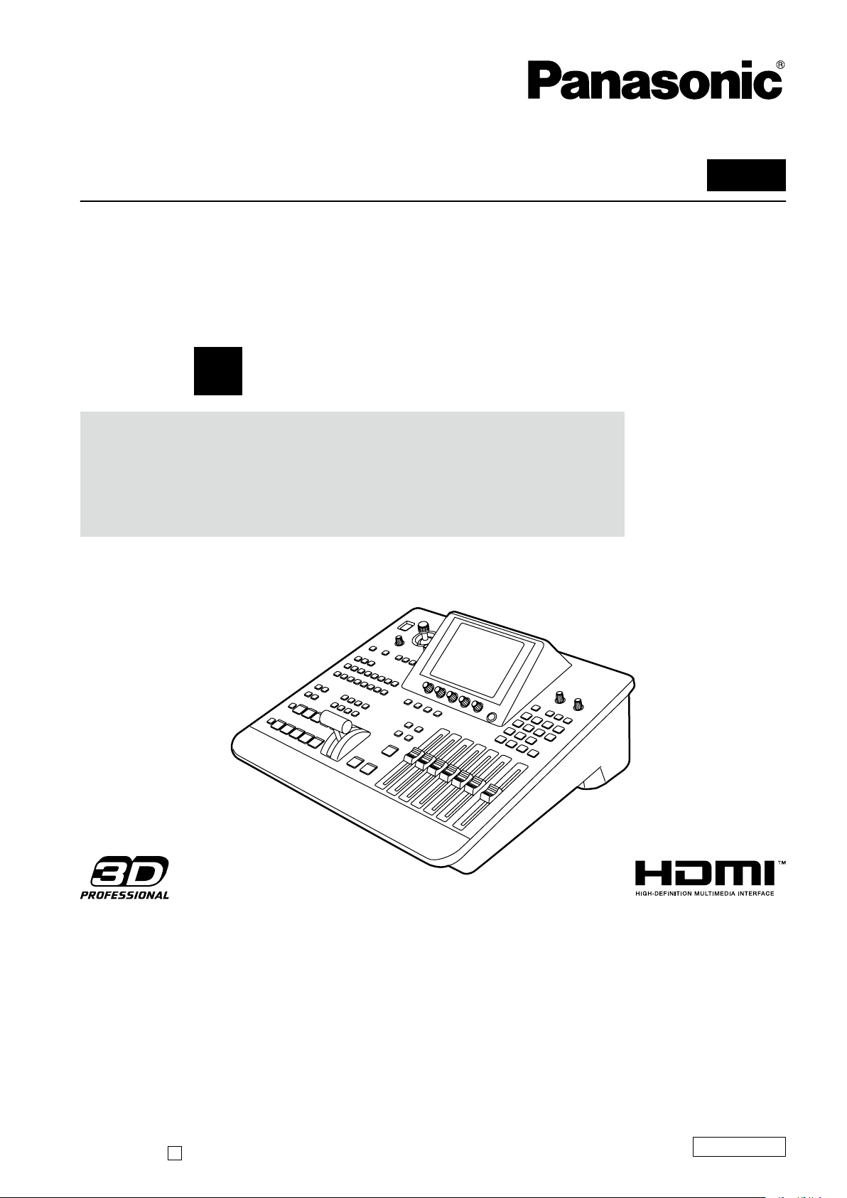
Digital AV Mixer
Model No. AG-HMX100P
Model No. AG-HMX100E
Vol.1
Volume
Note that Operating Instructions Vol. 1 describes basic
operations of the digital AV mixer.
For instructions on advanced operations of the digital
AV mixer, refer to Operating Instructions Vol. 2 (pdf file)
contained in the supplied CD-ROM.
1
Before operating this product, please read the instructions carefully and save this manual for future use.
SS0810RI0 -PS
Printed in Japan
D
ENGLISH
VQT2U23
Page 2
2
Read this first! (For AG-HMX100P)
CAUTION:
The mains plug of the power supply cord shall
remain readily operable.
The AC receptacle (mains socket outlet) shall be
installed near the equipment and shall be easily
accessible.
To completely disconnect this equipment from the
AC mains, disconnect the mains plug from the AC
receptacle.
CAUTION:
In order to maintain adequate ventilation, do not
install or place this unit in a bookcase, built-in
cabinet or any other confined space. To prevent
risk of electric shock or re hazard due to
overheating, ensure that curtains and any other
materials do not obstruct the ventilation.
CAUTION:
To reduce the risk of re or electric shock and
annoying interference, use the recommended
WARNING:
This equipment must be grounded.
To ensure safe operation, the three-pin plug
must be inserted only into a standard threepin power outlet which is effectively grounded
through normal household wiring.
Extension cords used with the equipment must
have three cores and be correctly wired to
provide connection to the ground. Wrongly wired
extension cords are a major cause of fatalities.
The fact that the equipment operates
satisfactorily does not imply that the power outlet
is grounded or that the installation is completely
safe. For your safety, if you are in any doubt
about the effective grounding of the power
outlet, please consult a qualified electrician.
accessories only.
CAUTION:
This apparatus can be operated at a voltage in
the range of 100 – 240 V AC.
Voltages other than 120 V are not intended for
U.S.A. and Canada.
Operation at a voltage other than 120 V AC may
require the use of a different AC plug. Please
contact either a local or foreign Panasonic
authorized service center for assistance in
selecting an alternate AC plug.
CAUTION:
Excessive sound pressure from earphones and
headphones can cause hearing loss.
WARNING:
• To reduce the risk of re or electric shock, do
not expose this equipment to rain or moisture.
• To reduce the risk of re or electric shock,
keep this equipment away from all liquids.
Use and store only in locations which are not
exposed to the risk of dripping or splashing
liquids, and do not place any liquid containers
on top of the equipment.
indicates safety information.
Page 3

3
S3125A
Read this first! (For AG-HMX100P) (continued)
IMPORTANT SAFETY INSTRUCTIONS
1) Read these instructions.
2) Keep these instructions.
3) Heed all warnings.
4) Follow all instructions.
5) Do not use this apparatus near water.
6) Clean only with dry cloth.
7) Do not block any ventilation openings. Install in accordance with the manufacturer’s instructions.
8) Do not install near any heat sources such as radiators, heat registers, stoves, or other apparatus (including ampliers)
that produce heat.
9) Do not defeat the safety purpose of the polarized or grounding-type plug. A polarized plug has two blades with one
wider than the other. A grounding-type plug has two blades and a third grounding prong. The wide blade or the
third prong are provided for your safety. If the provided plug does not fit into your outlet, consult an electrician for
replacement of the obsolete outlet.
10) Protect the power cord from being walked on or pinched particularly at plugs, convenience receptacles, and the point
where they exit from the apparatus.
11) Only use attachments/accessories specied by the manufacturer.
12) Use only with the cart, stand, tripod, bracket, or table specied by the manufacturer, or sold with the
apparatus. When a cart is used, use caution when moving the cart/apparatus combination to avoid injury
from tip-over.
13) Unplug this apparatus during lightning storms or when unused for long periods of time.
14) Refer all servicing to qualied service personnel. Servicing is required when the apparatus has been
damaged in any way, such as power-supply cord or plug is damaged, liquid has been spilled or objects have fallen into
the apparatus, the apparatus has been exposed to rain or moisture, does not operate normally, or has been dropped.
Page 4

4
Read this first! (For AG-HMX100P) (continued)
FCC NOTICE (U.S.A.)
Declaration of Conformity
Model Number: AG-HMX100P
Trade Name: Panasonic
Responsible Party: Panasonic Corporation of North America
One Panasonic Way, Secaucus, NJ07094
Support contact: 1-800-524-1448
This device complies with Part 15 of the FCC Rules.
Operation is subject to the following two conditions:
(1)This device may not cause harmful interference, and (2) this device must accept any interference received, including
interference that may cause undesired operation.
To assure continued compliance, follow the attached installation instructions and do not make any unauthorized
modifications.
Note:
This equipment has been tested and found to comply with the limits for a class B digital device, pursuant to Part 15 of
the FCC Rules. These limits are designed to provide reasonable protection against harmful interference in a residential
installation. This equipment generates, uses, and can radiate radio frequency energy, and if not installed and used
in accordance with the instructions, may cause harmful interference to radio communications. However, there is no
guarantee that interference will not occur in a particular installation. If this equipment does cause harmful interference to
radio or television reception, which can be determined by turning the equipment off and on, the user is encouraged to try
to correct the interference by one of the following measures:
• Reorient or relocate the receiving antenna.
• Increase the separation between the equipment and receiver.
• Connect the equipment into an outlet on a circuit different from that to which the receiver is connected.
• Consult the dealer or an experienced radio/TV technician for help.
The user may nd the booklet “Something About Interference” available from FCC local regional ofces helpful.
Warning:
To assure continued FCC emission limit compliance, follow the attached installation instructions and the user must use
only shielded interface cables when connecting to host computer or peripheral devices. Also, any unauthorized changes
or modications to this equipment could void the user’s authority to operate this device.
Page 5
5
Read this first! (For AG-HMX100E)
WARNING:
This equipment must be earthed.
To ensure safe operation, the three-pin plug
must be inserted only into a standard three-pin
power point which is effectively earthed through
normal household wiring.
Extension cords used with the equipment must
have three cores and be correctly wired to
provide connection to the earth. Wrongly wired
extension cords are a major cause of fatalities.
The fact that the equipment operates
satisfactorily does not imply that the power point
is earthed or that the installation is completely
safe. For your safety, if you are in any doubt
about the effective earthing of the power point,
please consult a qualified electrician.
WARNING:
• To reduce the risk of re or electric shock, do
not expose this equipment to rain or moisture.
• To reduce the risk of re or electric shock,
keep this equipment away from all liquids.
Use and store only in locations which are not
exposed to the risk of dripping or splashing
liquids, and do not place any liquid containers
on top of the equipment.
CAUTION:
The mains plug of the power supply cord shall
remain readily operable.
The AC receptacle (mains socket outlet) shall be
installed near the equipment and shall be easily
accessible.
To completely disconnect this equipment from
the AC mains, disconnect the mains plug from
the AC receptacle.
CAUTION:
In order to maintain adequate ventilation, do not
install or place this unit in a bookcase, built-in
cabinet or any other confined space. To prevent
risk of electric shock or re hazard due to
overheating, ensure that curtains and any other
materials do not obstruct the ventilation.
CAUTION:
To reduce the risk of re or electric shock and
annoying interference, use the recommended
accessories only.
CAUTION:
Excessive sound pressure from earphones and
headphones can cause hearing loss.
CAUTION:
Do not remove panel covers by unscrewing
them.
To reduce the risk of electric shock, do not
remove the covers. No user serviceable parts
inside.
Refer servicing to qualied service personnel.
indicates safety information.
If the unit is not going to be used for length of time, turn the power OFF and disconnect the power from the AC outlet.
Page 6
6
Fuse
Read this first! (For AG-HMX100E) (continued)
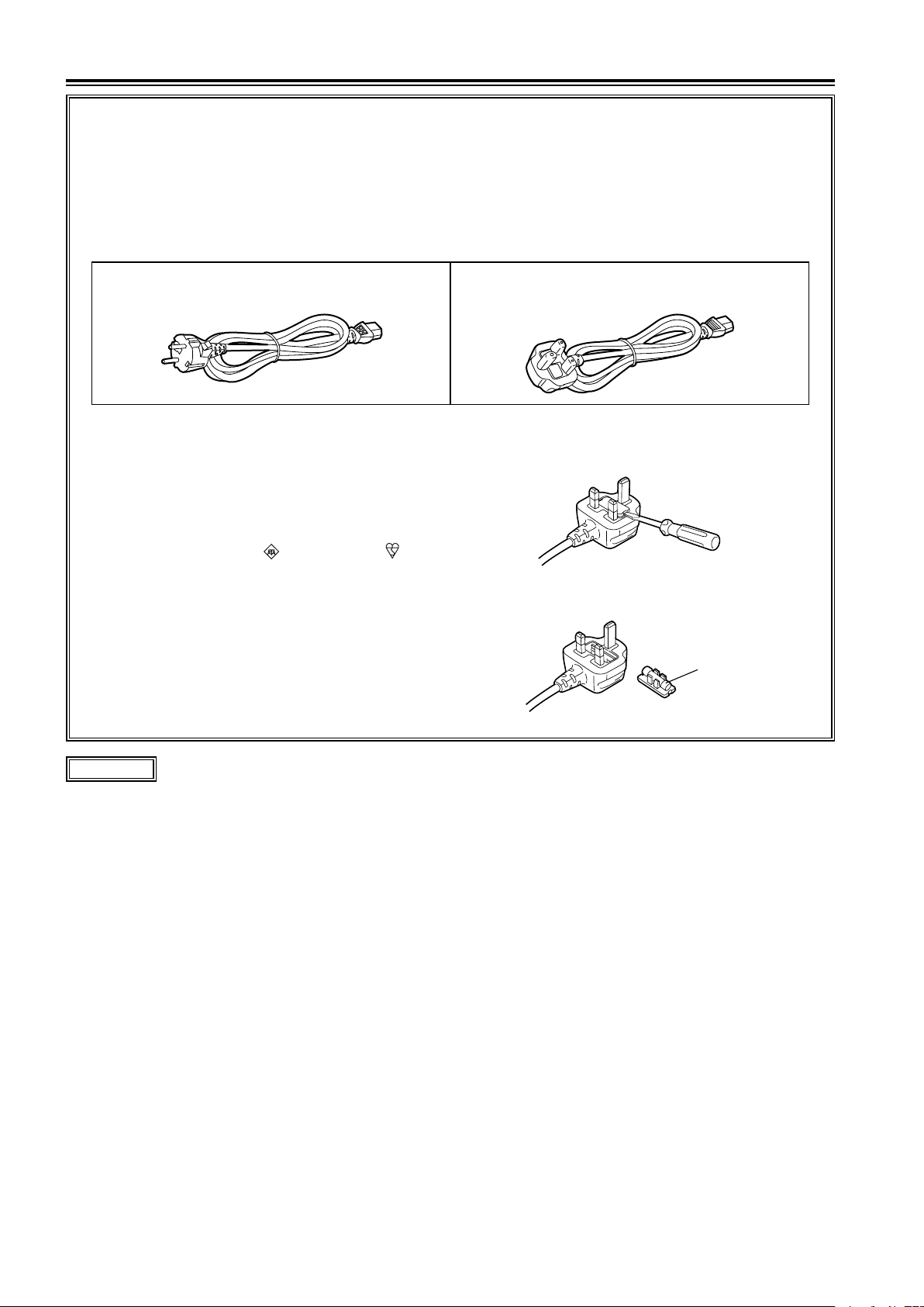
Caution for AC Mains Lead
FOR YOUR SAFETY PLEASE READ THE FOLLOWING TEXT CAREFULLY.
This product is equipped with 2 types of AC mains cable. One is for continental Europe, etc. and the other one is
only for U.K.
Appropriate mains cable must be used in each local area, since the other type of mains cable is not suitable.
FOR CONTINENTAL EUROPE, ETC.
Not to be used in the U.K.
FOR U.K. ONLY
This appliance is supplied with a moulded three pin
mains plug for your safety and convenience.
A 13 amp fuse is fitted in this plug.
Should the fuse need to be replaced please ensure that
the replacement fuse has a rating of 13 amps and that
it is approved by ASTA or BSI to BS1362.
Check for the ASTA mark or the BSI mark on the
body of the fuse.
If the plug contains a removable fuse cover you must
ensure that it is refitted when the fuse is replaced.
If you lose the fuse cover the plug must not be used
until a replacement cover is obtained.
A replacement fuse cover can be purchased from your
local Panasonic Dealer.
FOR U.K. ONLY
How to replace the fuse
1.Open the fuse compartment with a screwdriver.
2.Replace the fuse.
indicates safety information.
EEE Yönetmeliğine Uygundur.
EEE Complies with Directive of Turkey.
Page 7

7
Read this first! (For AG-HMX100E) (continued)
EMC NOTICE FOR THE PURCHASER/USER OF THE APPARATUS
1. Applicable standards and operating environment (AG-HMX100E)
The apparatus is compliant with:
• standards EN55103-1 and EN55103-2 1996.11, and
• electromagnetic environments E1, E2, E3 and E4
2. Pre-requisite conditions to achieving compliance with the above standards
<1> Peripheral equipment to be connected to the apparatus and special connecting cables
• The purchaser/user is urged to use only equipment which has been recommended by us as
peripheral equipment to be connected to the apparatus.
• The purchaser/user is urged to use only the connecting cables described below.
<2> For the connecting cables, use shielded cables which suit the intended purpose of the
apparatus.
• Video signal connecting cables
Use double shielded coaxial cables, which are designed for 75-ohm type high-frequency
applications, for SDI (Serial Digital Interface).
Coaxial cables, which are designed for 75-ohm type high-frequency applications, are
recommended for analog video signals.
• Audio signal connecting cables
If your apparatus supports AES/EBU serial digital audio signals, use cables designed for AES/EBU.
Use shielded cables, which provide quality performance for high-frequency transmission
applications, for analog audio signals.
• Other connecting cables (IEEE1394, USB)
Use shielded cables, which provide quality performance for high-frequency applications, as
connecting cables.
• When connecting to the DVI signal terminal, use a cable with a ferrite core.
• If your apparatus is supplied with ferrite core(s), they must be attached on cable(s) following
instructions in this manual.
3. Performance level
The performance level of the apparatus is equivalent to or better than the performance level required by
these standards.
However, the apparatus may be adversely affected by interference if it is being used in an EMC
environment, such as an area where strong electromagnetic fields are generated (by the presence
of signal transmission towers, cellular phones, etc.). In order to minimize the adverse effects of the
interference on the apparatus in cases like this, it is recommended that the following steps be taken with
the apparatus being affected and with its operating environment:
1. Place the apparatus at a distance from the source of the interference.
2. Change the direction of the apparatus.
3. Change the connection method used for the apparatus.
4. Connect the apparatus to another power outlet where the power is not shared by any other
appliances.
Pursuant to at the directive 2004/108/EC, article 9(2)
Panasonic Testing Centre
Panasonic Service Europe, a division of Panasonic Marketing Europe GmbH
Winsbergring 15, 22525 Hamburg, F.R. Germany
Page 8
Contents
Volume 1 (This Book)
Requests on Use ....................................9
OVERVIEW.............................................10
Features ....................................................................... 10
AV Mixer Functions
Accessories
Components and Functions
Operation Panel (Front)
Connector Area (Rear)
................................................................ 12
....................................................11
..................................... 13
............................................. 13
.............................................. 15
Basic Operation ....................................16
System Configuration Examples .............................. 16
SD Video Processing System.................................... 16
HD Video Processing System
System with External Controller
Power-On
Power-Off
Initial Setup
HD/SD Settings
Setting Screen
Basic Operation of Menus
[SETUP] Menu (Setup Operation) Screen
Setting the Startup Mode [MODE]
Changing Direct Patterns [DIRECT PATTERN]
Setting Video and Audio Input Sources
Setting the Video Format [VIDEO FORMAT]
..................................................................... 19
.................................................................. 19
................................................................. 19
......................................................... 19
........................................................... 20
[AUDIO VIDEO] ..................................................... 24
................................... 17
................................ 18
........................................ 21
................ 22
............................ 22
......... 23
............ 26
Setting the Bus [BUS] ............................................... 27
Setting Audio Channels [AUDIO CH]
Setting the Audio Faders [AUDIO FADER]
[INT VIDEO] Menu (Internal Video Setting) Screen
Setting the Back Matte [BACK MATTE]
Outputting Color Bars [COLOR BAR] ....................... 30
Using Still Pictures or Movies as Internal Video
[MEMORY]
Using Video Input from PC [PC1]
Switching or Combining of Video
Selecting Source Video and Sound
Checking (Previewing) Video and Sound
Adjusting the Audio Level
AB Transition
Program Preset Transition
Keying
Downstream Key (DSK)
Fade
.......................................................................... 38
............................................................. 30
......................................... 33
............................................................. 34
......................................... 35
....................................................................... 35
............................................ 36
...................... 27
............... 27
.. 28
....................29
.............................32
.............................33
.......................... 33
................. 33
Before Calling for Service ....................39
Troubleshooting .......................................................... 39
Specifications .......................................40
Signal Format Supported on the Unit ....................... 42
Signal Format Supported on the Unit in 3D Mode... 43
Index ......................................................44
Volume 2 (CD)
Chapter 1 Applying Effects to Video and Sound
Chapter 2 Registering Settings and Effects
Chapter 3 Switching 3D Video
Chapter 4 Operating Environment Setting
“HDMI”, the HDMI logo, and “High-Denition multimedia interface” are trademarks or registered trademarks of HDMI
Licensing LLC.
All other company names and product names are trademarks or registered trademarks of their respective companies.
Index
List of Transition Patterns
List of Key Patterns
Reference pages
See pages shown as “ page 00” to obtain more information.
8
Page 9

9
Requests on Use
Do not use this equipment near radio transmitters or high-voltage equipment or do not generate static electricity to this
equipment as it may adversely affect the recorded images, sound, operation, LED (indication), and the like.
Keep this equipment away from equipment that generates magnetic elds or electromagnetic waves.
The powerful magnetic elds generated by speakers or large motors may adversely affect the recorded images and/or
sound.
The liquid crystal parts are highly precise with 99.99 % of the pixels effective. This leaves less than 0.01 % of pixels that
may not light or may remain on all the time. These phenomena are normal.
The response speed, brightness, and color contrast of the liquid crystal parts vary with the operating temperature and
•
viewing angle.
Operate the CONTRAST control to get the clear display when necessary.
•
Do not give any vibration, impact, or static electricity to this equipment during operation.
When you need to transport this equipment, use great care not to give excessive vibration or impact.
Page 10

10
Overview
OVERVIEW
Panasonic AG-HMX100P/HMX100E is an HD/SD-compatible digital Audio Visual mixer equipped with the essential
functions of video switchers, digital video effectors, and audio mixers.
Features
Video switching/combining effects
Video can be processed with wipe, mix, chroma key, luminance key, and digital video effect (DVE) combinations as well as
downstream key (DSK) and fade functions.
Various digital effects
Desired effects can be added to video including still, strobe, negative, monochrome, multi-strobe (division into 4, 9, or 16),
mirror, mosaic, and paint. The screen display mode can be selected from Field and Frame for the still, strobe, and multistrobe effects.
Audio mixing
Ten sets of audio input sources can be adjusted and mixed.
Event memory
Up to 100 patterns for the settings of this unit can be stored as “events.”
Multi-view and auxiliary (AUX) outputs
In addition to the connectors for program output*1 and preview output*2, this unit is equipped with multi-view connectors
used to display all input sources on the same screen and AUX connectors used for various outputs.
Waveform display
Multi-view output displays waveforms for input signal check on the monitor.
3D camera supported
Two pairs of L and R channels are available to input 3D camera video sources and can be switched between them.
External controller connection
GPI and RS-232C connectors are equipped to connect an external controller.
Projector control
Panasonic projector connected can be controlled from this unit to turn on/off the power and shutter (RS-232C control).
Frame synchronizer
The built-in frame synchronizer can be used for frame alignment of all input sources, requiring no synchronization of input
signals.
Advanced reference
The reference signal is output with the vertical phase advanced for input signals.
*1 Program output: Final video and sound output from this unit with effects applied.
*2 Preview output: Video and sound output for checking the effects before actually applying them.
Page 11
AV Mixer Functions
The following shows the operation examples for video production with the AV mixer functions.
Overview
Basic Operation (see “Operation
Manual Volume 1 ”)
Configuring a system ( page 16)
Starting the unit ( page 19)
Setup ( page 19)
Setting the startup mode (•
Changing direct patterns (
•
Setting video and audio input sources
•
( page 24)
Setting the video format (
•
Setting the bus*
•
Setting the audio output channels (
•
Setting the audio fader (
•
Setting the internal video (
•
Setting video created on PC (
•
1
( page 27)
page 22)
page 26)
page 27)
page 28)
page 23)
page 32)
page 27)
Applied Operation (see the pdf manual in the
CD-ROM, “Operation Manual Volume
Operating environment setting ( page Vol.2-26)
Setting the System (•
Setting the memory (
•
Setting the audio level (
•
Setting the external synchronization (
•
Setting details for connecting PC (
•
Setting for external interface (
•
page
page
page
Vol.2-26
Vol.2-27
Vol.2-27
page
)
)
)
page
page
Vol.2-28
Vol.2-28
”)
2
Vol.2-28
)
)
)
Selecting video to use ( page 33) Using 3D video ( page Vol.2-22)
Adjusting video (• page Vol.2-13)
Adjusting/mixing sound (• page Vol.2-17)
Setting the video switching (transition) effect •
( page 34)
Inserting (keying) characters or graphics into •
video ( page 35)
Setting the downstream key (• page 36)
Setting the fade effect (• page 38)
Executing transition or keying
(
pages 34 to 38)
Checking (previewing) video and sound
( page 33)
Setting the transition wipe pattern (• page Vol.2-3)
Setting the pattern key (• page Vol.2-5)
Setting the chroma key (• page Vol.2-6)
Setting the luminance key (• page Vol.2-7)
Setting the title key (• page Vol.2-8)
Advanced setting for the downstream key •
( page Vol.2-11)
Registering the settings ( page Vol.2-19)
*1 Bus: Refers to a path of signals input/output to/from this unit. You can select the bus system from the AB bus system
and the Preset/Program bus system on this unit ( page 27).
11
Page 12

Overview
Accessories
Power cable ×1 for AG-HMX100P, ×2 for AG-HMX100E
CD-ROM ×1
NOTE
Be sure to appropriately dispose of the packing material when you have unpacked the product.•
Consult your supplier regarding purchase of accessories.•
12
Page 13
13
Overview
Components and Functions
POS.
WIDTH
32
PATTERN
EFFECTS
EDGE HARD
MODIFY
OFF
OFF
COLOR
WHITE
EVENT
TRANSITION
ME TIME PATTERN INT
09 E 04:25 F 0016
WHT
X 128
Z 127
Y 220
POWER
X / Y
PB / P
R
ASPECT
Z
H
V
ON
CENTER
SCENE
GRABBER
PROJECTOR/
REMOTE
HOLD
P in P
PATTERN
REVERSE
MIX
ONE
WAY
DSK
EFFECTS
EXT
KEY
CHROMA
KEY
LUM
KEY
PREVIEW
ME
PVW
DSK
A/
PROG
A/
PROG
STILL STROBE
VIDEO
EFFECTS
COLOR
EFFECTS
B/
PRESET
B/
PRESET
EFFECTS
A / PROG
B / PRESET
SHIFT
SOURCE
1 / 5 2 / 6 3 / 7 4 / 8
SOURCE SOURCE SOURCE
INT
MIX EFFECTS
FADE
DSK
AUTO
TAKE
SET UP
INT
VIDEO
DSK
FADE
AUDIO
EFFECTS
CONTRAST
EVENT
RECALL
EFFECTS
ON
FOLLOW
VIDEO
SET
AUDIO
MAX MAX
MIN MIN
MASTER
SOURCE
1 / 5
SOURCE
2 / 6
SOURCE
3 / 7
SOURCE
4 / 8
AUX MIC
7
8 9
65
4
1
0
.
2
SHIFT
3
PHONES TIME
PATTERN
CANCELINT PLAY
ME
DSK FADE
MIN MAX
22
1
4
23
19
17 16 15
9 1211 1332 5 10 146 7 8
21
25 2427 26 20 18
Operation Panel (Front)
1 POWER button ( page 19)
2 PROJECTOR/REMOTE button ( pages 18, Vol.2-28)
3 ASPECT control and button ( page 36)
4 Joystick ( pages 20, 28, 30, 34, 36, Vol.2-4, Vol.2-6,
5 Rotary Z control ( pages 20, 28, 30, 36, Vol.2-13)
6 HOLD button ( pages 34, 36)
CENTER button ( pages 34, 36, Vol.2-13)
SCENE GRABBER button ( page 36)
7 Menu buttons
• SETUP button ( page 22)
Vol.2-13)
• INT VIDEO button ( page 28)
• DSK FADE button ( page Vol.2-11)
• AUDIO EFFECTS button ( page Vol.2-17)
8 Rotary 1 (leftmost), 2, 3, 4, and 5 (rightmost) controls
(
page 21)
9 LCD screen ( page 20)
10 CONTRAST control ( page 21)
11 PATTERN button ( page 35)
12 PHONES control ( page 33)
13 TIME rotary control and buttons
• TIME rotary control ( pages 35, 37, 38, Vol.2-9)
• ME*1 setting button ( page 35)
• DSK setting button ( page 37)
• FADE setting button ( page 38)
14 Numeric key area
• Numeric (0 to 9) keys ( pages 35, 37, 38, Vol.2-6,
Vol.2-9, Vol.2-20)
• − (minus) key ( pages 35, Vol.2-20)
• + (plus) key ( pages 35, Vol.2-20)
*1 ME: M and E stand for Mix and Effect, respectively.
This function is used to mix or switch two inputs of A
and B.
Page 14

14
Overview
• . (period) key*1 ( pages 32, Vol.2-21)
P in P
PATTERN
REVERSE
MIX
ONE
WAY
DSK
EFFECTS
EXT
KEY
CHROMA
KEY
LUM
KEY
(6)(7)(8)(9)
(1)
(2) (3) (4)
(5)
• SHIFT key ( pages 27, 28, 30, 32, 33, Vol.2-4,
Vol.2-9, Vol.2-10, Vol.2-13, Vol.2-15)
• (confirm) key*
2
15 MASTER fader ( page 33)
16 MIC fader ( page 27, 28, 33)
17 AUX fader ( page 27, 28, 33)
18 SOURCE 1/5, 2/6, 3/7, 4/8 faders ( page 27)
19 AUDIO EFFECTS execution button ( page Vol.2-17)
AUDIO FOLLOW VIDEO button ( pages 33, 34, 38,
Vol.2-17)
20 FADE execution button ( page 38)
DSK execution button ( page 37)
AUTO TAKE button ( pages 34, 35, Vol.2-20)
21 EVENT RECALL button ( page Vol.2-20)
EVENT SET button ( page Vol.2-20)
22 Transition lever ( pages 23, 34, 35)
23 B/PRESET bus source selector buttons ( page 24)
• SHIFT button
• SOURCE 1/5, 2/6, 3/7, 4/8 buttons
• INT button
24 A/PROG bus source selector buttons ( page 24)
• SHIFT button
• SOURCE 1/5, 2/6, 3/7, 4/8 buttons
• INT button
25 EFFECTS buttons for A/PROG and B/PRESET buses
(
pages Vol.2-13, Vol.2-15)
• STILL buttons ( page Vol.2-15)
• STROBE buttons ( page Vol.2-15)
• VIDEO EFFECTS buttons ( page Vol.2-13)
• COLOR EFFECTS buttons ( page Vol.2-13)
26 PREVIEW buttons ( page 33)
• ME PVW button
• A/PROG selector button
• B/PRESET selector button
• DSK selector button
27 PATTERN area ( pages 23, 34, 36, Vol.2-6, Vol.2-7)
(1) REVERSE button ( page 36)
(2) ONE WAY button ( page 34)
(3) DSK EFFECTS button ( page 37)
(4) Direct key pattern buttons ( pages 23, 35)
(5) Direct transition pattern buttons ( pages 23, 34)
(6) MIX button ( page Vol.2-3)
(7) LUM KEY button ( page Vol.2-7)
(8) CHROMA KEY button ( page Vol.2-6)
(9) EXT KEY button ( page Vol.2-7)
*1 Factions as the INT PLAY key when pressed with the
SHFIT key.
2
*
Factions as the CANCEL key when pressed with the
SHFIT key.
Page 15
15
Overview
Connector Area (Rear)
~AC IN
1
L R
2
L R
3
L R
4
L R L R
VIDEO IN GPI
AUX IN
L R L R RS-232C
TALLY
SIGNAL
GND
AUDIO OUT 2
G/L ADV-REF
SDI IN
SDI OUT MIC PHONES
1
1 2
3
DVI-I IN DVI-D OUT
4 PGM
IN 1
IN 2
PVW AUX
PGM MULTI VIEW
MULTI VIEW
2
AUDIO IN AU DIO OUT 1
3 4 51
1718 16 15 13 12 10
2 6 7
11
8 9
14
For devices and signals which can be connected to
each connector, see “System Conguration Examples”
(
page 16) and “Example Connections with 3D Camera”
( pages Vol.2-22 to 24).
NOTE
For the DVI-I IN connector and DVI-D IN connectors, shielded •
DVI cables with noise suppression core are recommended.
For transmitting HD-SDI signals via the SDI IN 1 to 4 •
connectors and SDI OUT connectors, cables equivalent or
superior to the 5C-FB or 5C-FW cable are recommended.
When signals with the Copy Guard function applied are •
input to the HDMI IN, DVI-I IN or VIDEO IN connector, neither
image nor sound is output (a black image appears).
1 SDI IN 1 to 4 connectors
2 DVI-I IN connector ( pages 32, Vol.2-28)
3 HDMI IN 1, 2 connectors ( pages 17, 18)
4 DVI-D OUT connectors
• PGM connector
• MULTI VIEW connector
5 PHONES connector ( page 33)
6 RS-232C connector ( page Vol.2-28)
7 TALLY connector ( page Vol.2-29)
8 AC IN power socket
9 GND terminal
10 AUDIO OUT 2 L and R connectors (unbalanced
output)
11 AUDIO OUT 1 L and R connectors (balanced output)
12 AUX IN L and R connectors
13 MIC connector
14 GPI connector ( page Vol.2-26)
15 SDI OUT connectors
• PGM connector
• PVW connector
• AUX connector
• MULTI VIEW connector
16 G/L connector ( page Vol.2-28)
ADV-REF connector ( page Vol.2-28)
17 AUDIO IN 1 to 4 L and R connectors
18 VIDEO IN 1, 2 connectors
Page 16

16
Basic Operation
SDI OUT PGM
SDI OUT PVW
SDI OUT AUX
DVI-D OUT PGM
DVI-D OUT
MULTI VIEW
DVI-I
IN
AUDIO
IN
MIC
SDI IN 1
SDI IN 2
SDI IN 3
SDI IN 4
VIDEO IN 1
VIDEO IN 2
SDI OUT MULTI VIEW
G/LADV-REF
Basic Operation
This chapter describes the initial setup operation for video processing and audio mixing, and the operation of selecting
video and audio sources, and setting the basic video switching effects.
System Configuration Examples
This unit can be connected to video equipment including cameras, P2 devices and VTRs to digitally process video and
sound input sources.
The following shows the connection examples of this unit with external equipment in three types of system configurations: a
system for processing SD video, a system for processing HD video, and a system operated from an external controller.
SD Video Processing System
Advanced
reference signal*
System camera
Loop-
through
System camera
SDI (video and
audio) input
1
G/L external
sync signal*
Signal generator
Program output
Preview output
1
Termi-
nation
Professional-use
VTR
P2 mobile
Composite
input
Professional-use
video camera
Professional-use
video camera
SDI
(video
and
audio)
input
Composite
input
MIC
AG-HMX100P/HMX100E
MIC input
Analog
DVI-I
input
audio
input
SDI output
Program output
DVI-D output
PC
Professional-use
audio equipment
Multi-
view
output
Multi-
view
output
Professional-use
monitor
AUX output
Professional-use
projector
Home-use
television
*1 Advanced reference signal or G/L external sync signal need not necessarily be connected.
Page 17

HD Video Processing System
ADV-REF G/L
SDI OUT PGM
SDI OUT PVW
SDI OUT AUX
DVI-D OUT PGM
DVI-D OUT
MULTI VIEW
DVI-I
IN
MIC
SDI IN 1
SDI IN 2
SDI IN 3
SDI IN 4
HDMI IN 1
HDMI IN 2
SDI OUT MULTI VIEW
AUDIO
IN
Advanced
reference signal*
Basic Operation
1
Loop-
through
Termination
Home-use video camera
System camera
Professional-use
camera
Professional-use
camera
P2 mobile
HDMI input
SDI (video and
audio) input
SDI
(video
and
audio)
input
HDMI input
G/L external
sync signal*
AG-HMX100P/HMX100E
MIC input
DVI-I
input
1
SDI output
DVI-D output
Multi-
view
output
Program output
Multi-
view
output
Signal generator
Program output
Preview output
Professional-use
monitor
AUX output
Professional-use
projector
Analog
audio
input
Professional-use
video camera
*1 Advanced reference signal or G/L external sync signal need not necessarily be connected.
MIC
PC
Professional-use
audio equipment
Home-use
television
17
Page 18

18
Basic Operation
System with External Controller
ADV-REF
RS-232C
G/L
SDI OUT PGM
SDI OUT PVW
SDI OUT AUX
DVI-D OUT PGM
DVI-D OUT
MULTI VIEW
DVI-I
IN
MIC
SDI IN 1
SDI IN 2
SDI IN 3
SDI IN 4
HDMI IN 1
HDMI IN 2
SDI OUT MULTI VIEW
AUDIO
IN
For using an external controller, it is necessary to perform the following operations in advance:
Enter this unit to remote mode using the [RS-232C] submenu of the [SETUP] menu (
• page Vol.2-29).
• Press the PROJECTOR/REMOTE button to turn on to activate RS-232C control.
External
controller
Loop-
through
Professional-use
Professional-use
Termination
System camera
camera
camera
P2 mobile
SDI (video and
audio) input
SDI
(video
and
audio)
input
Advanced
reference signal*
AG-HMX100P/HMX100E
1
Signal generator
Program output
G/L external
sync signal*
1
SDI output
Program output
Multi-
view
output
Preview output
Professional-use
LCD monitor
AUX output
HDMI input
DVI-D output
HDMI input
Home-use video camera
Professional-use
video camera
*1 Advanced reference signal or G/L external sync signal need not necessarily be connected.
MIC
MIC input
Analog
audio
input
DVI-I
input
PC
Professional-use
audio equipment
Multi-
view
output
Professional-use
projector
Home-use
television
Page 19

19
Basic Operation
Power-On
Use the supplied power cord to connect this unit to an AC power source.
1
Press the POWER button.
2
To specify the initial state of the unit when it is restarted
Use the [MODE] submenu of the [SETUP] menu to set the startup mode ( page 22).
Preset mode: The last settings are restored when the unit is restarted. The factory default setting is this mode.
Reset mode: The factory default settings are restored when the unit is restarted. However, some settings remain in the
previous state including those of the [SETUP] menu.
Factory default mode: The factory default settings are restored when the unit is restarted.
Power-Off
Keep pressing down the POWER button for 3 seconds or more, and the power of this unit is turned off.
Initial Setup
When you use Panasonic AG-HMX100P/HMX100E for the rst time, you need to make the settings as described below with
the [SETUP] menu (
page 22) and [INT VIDEO] menu ( page 28) to set up this unit.
Setting the startup mode (• page 22)
Changing direct patterns (• page 23)
Setting video and audio input sources (• page 24)
Setting the video format (• page 26)
Setting the bus (• page 27)
Setting the audio output channels (• page 27)
Setting the audio fader (• page 27)
Setting the back matte video (• page 29)
Outputting the color bars (• page 30)
Setting still pictures or movies (• page 30)
Setting video created on PC (• page 32)
HD/SD Settings
This unit is not available for mixing different formats of input signals. Thus, it cannot input HD video and SD video at the
same time to perform the mixing operation.
Depending on whether to input HD video or SD video as an input source, the system format of this unit must be set to “HD”
or “SD,” respectively in the following way.
The system format can be changed from the [VIDEO FORMAT] submenu of the [SETUP] menu (
To set the system format to HD: Select 720/50p, 720/59p, 1080/50i, or 1080/59i.
To set the system format to SD: Select 480/59i or 576/50i.
page 25).
Page 20

20
Basic Operation
Setting Screen
POS.
MOSAIC SIZE
OFF XY 0
OFF 0
DEFOCUS LEVEL
OFF
MONO
EVENT
VIDEO EFFECTS
CH A
ME TIME PATTERN INT
00 E
2:00 F 3044
WHT
X 128
Z 196 FAN STOP
Y 128
1 2 3
54 6
When setting up this unit or adjusting functions, you need to check the current settings on the LCD screen.
The following shows the basic configuration of the setting screen.
1 Joystick, rotary Z control settings, and 3D display
area
Shows the setting values of the joystick and rotary Z
control; X, Y, and Z values during position setting and
P
, PR, and C GAIN values during color setting.
B
When this unit is in 3D mode (
displayed.
2 Audio level meter
Indicates the audio output level.
3 Error Message
An error message appears in the following cases.
Message Condition and Action
FAN STOP The fan has stopped from any cause.
Immediately turn off the power and
request a service call (
CHANGE HDMI
FORMAT
CHANGE HDMI1
FORMAT
CHANGE HDMI2
FORMAT
HDMI input source in the format other
than the system formats (
available for this unit is being
connected to this unit.
CHANGE HDMI FORMAT: Input
sources of both HDMI IN
connectors are in unavailable
formats.
CHANGE HDMI1 FORMAT:
Input source of the HDMI IN 1
connector is in unavailable format.
CHANGE HDMI2 FORMAT:
Input source of the HDMI IN 2
connector is in unavailable format.
Change the system format setting or
the input source setting.
page Vol. 2-25), [3D] is
page 39).
page 19)
NOTE
The “FAN STOP” error message is also displayed on the
multi-view screen. However, since the multi-view screen
does not open when this unit is in 3D mode ( page
Vol.2-25), no error message is displayed even if the fan
stops. Pay attention to a message which will appear on the
LCD.
If two types of errors occur at the same time, “FAN STOP”
is displayed preferentially.
4 Event number, transition time, pattern number, and
internal video display area
EVENT: Shows the event number (
ME TIME: Shows the setting value of transition time
(
page 35); DSK TIME value during downstream
key setting ( page 37) and FADE TIME value
during fade setting ( page 38).
To change the TIME type, press the applicable
transition time setting button (ME, DSK, or FADE) to
turn on.
PATTERN: Shows the number of the currently selected
pattern (
INT: Shows the type of the currently selected internal
(internally generated) video (
5 Menu title, related information, rotary 1 to 5
parameter display area
Shows the title of the currently selected menu
(
page 21) (e.g., VIDEO EFFECTS), bus settings
(A/B), related information (color settings, etc), and
setting positions of rotary 1 to 5 controls.
page 35).
page Vol.2-20).
page 28).
Page 21

21
Basic Operation
6 Menu display area
Shows the setting items and values of the currently
selected menu.
The leftmost column has the setting items and the
second to fourth columns have the setting values. (The
leftmost column shows the setting values when the
[COLOR EFFECTS] menu is displayed.)
The setting items and values are displayed three lines
at a time.
The rotary 1 or 2 control can be used to scroll the
display.
The currently selected setting item is displayed in
reverse video (white on black).
To adjust the LCD contrast
Operate the CONTRAST control.
Before adjustment, see “Requests on Use” (
page 9).
Basic Operation of Menus
Menus are used to set up this unit or adjust functions. This
section describes how to select a menu and change the
settings.
The following table shows the menu titles and settings
available on this unit.
List of menus
Menu Title Settings
[SETUP] Setting up (
[INT VIDEO] Setting internal video ( page 28)
[DSK FADE] Setting the downstream key/fade
(
page Vol.2-11)
[AUDIO EFFECTS] Setting audio effects
(
page Vol.2-17)
[COLOR EFFECTS] Setting color effects
(
page Vol.2-13)
[VIDEO EFFECTS] Setting video effects
(
page Vol.2-13)
[LUMINANCE KEY] Setting the luminance key
(
page Vol.2-7)
[CHROMA KEY] Setting the chroma key
(
page Vol.2-6)
[EXT KEY] Setting the external key
(
page Vol.2-7)
[BASIC PATTERN
KEY]
[PATTERN KEY] Setting the pattern key
[TRANSITION] Setting transition wipe
[KEY LEARN] Setting key learn ( page Vol.2-9)
[TITLE KEY] Setting the title key ( page Vol.2-8)
[PROJECTOR] Setting the projector
Setting the basic pattern key
(
page Vol.2-5)
(
page Vol.2-5)
(
page Vol.2-3)
(
page Vol.2-29)
page 22)
To select the menu
For the [SETUP], [INT VIDEO], [DSK FADE], and [AUDIO
EFFECTS] menus, press the corresponding menu button.
For other menus, press the operation button related to the
settings.
For more information, see the description of each setting in
List of Menus.
If the menu is selected, the menu title, setting items,
and setting values are shown on the setting screen
(
page 20).
To select the setting item
Select the setting item in the menu display area using the
rotary 1 control (leftmost).
The currently selected item is displayed in reverse video
(displayed in white on black).
Three items each are displayed as the setting items.
When the setting item you want to select is not found, scroll
the screen using the rotary 1 control. (When the [AUDIO
EFFECTS] menu is selected, operate the rotary 2 control to
scroll the screen.)
To change the setting values
For the setting item displayed in reverse video (displayed
in white on black) in the menu display area, the setting
values can be changed.
The rotary 2 to 5 controls are used to change the setting
values in the second to fourth columns of the menu display
area. (The rotary 1 control is used to change the setting
value in the leftmost column when the [COLOR EFFECTS]
menu is displayed.)
Setting value in 2nd column Use the rotary 2 control.
Setting value in 3rd column Use the rotary 3 control.
Setting value in 4th column Use the rotary 4 control.
Setting value in 5th column Use the rotary 5 control.
Page 22

22
Basic Operation
[SETUP] Menu
POS.
MODE POWER
RESET
AUDIO INPUT
SETUPVIDEO
AUX
SDI1
WFM
SDI1
VIDEO
1080/59iFORMAT
ASPECT
- -
SETUP
- -
DIRECT
SETUPPATTERN
BUS TYPE
AB
MEMORY INT V3TITLE
3
AUDIO CH
SDI1CH
L-CH
1
R-CH 2OSD
ON
ON
AUDIO SOURCE
CP PAIRFADER
AUX/MIC
PAIR
AUDIO ALIGN.
0dBLEVEL
HEAD
dB*
1
PC1
ANALOG
FORMAT
SXGA
A.SET
PC2 H POSI 30V POSI 10PHASE 16CLOCK
1688
GEN. H PHASE
1000LOCK
FILE EMPTY
1 SAVE
SYSTEM1 TIME
SEC
GPI
ME
SYSTEM2 P.SAVE
OFF
SCR SAVE
10
HOURS M.
OFF
RS-232C B.RATE
9.6k
DATA L.
8BITS
PARITY
NONE PJ
3D MODE
OFF
FORMAT
- -
EVENT
SETUP
ME TIME PATTERN INT
00 E
01:00 F 3021
WHT
X 128
Z 196
Y 128
RESET
PRESET
FACTORY
MODE
RESET
POWER
Setting the Startup Mode [MODE]
(Setup Operation) Screen
When the SETUP button is pressed, the [SETUP] menu
screen appears as shown below.
The [SETUP] menu is used to make the basic settings for
the entire unit.
*1 20dB (AG-HMX100P) or 18dB (AG-HMX100E)
Rotary 1 Rotary 2 Rotary 3 Rotary 4 Rotary 5
Scroll the screen to display.
The [MODE] submenu of the [SETUP] menu is used to
specify how to reproduce the stored settings when this unit
is restarted (startup mode).
Rotary 1 Rotary 2 Rotary 3 Rotary 4 Rotary 5
To reset settings other than basic
settings to the factory default settings
when the unit is restarted
Set [POWER] to [RESET] (reset mode) using the rotary 2
control.
Settings other than [SETUP] menu settings, direct pattern
settings, event memory settings, le settings, and key learn
settings are reset to the factory default settings.
To reset all settings to the factory default
settings when the unit is restarted
Reset all settings to the factory default settings.
Set [POWER] to [FACTORY] (factory default
1
mode) using the rotary 2 control, and press the
key.
When the message [OK?] appears, press the
2
key.
To cancel the file save, press the key while
holding down the SHIFT key.
When the message “Please Wait…” appears
3
and then “TURN POWER OFF” appears, turn
off the power and restart the unit.
To restore the last settings when the unit
is restarted
Set [POWER] to [PRESET] (preset mode) using the rotary 2
control.
The following types of data are stored, and applied when
the unit is started next time.
[INT VIDEO] menu setting values
•
[COLOR EFFECTS], [VIDEO EFFECTS], and [AUDIO •
EFFECTS] menu setting values
Combinations of patterns registered as direct patterns
•
and numbers
Setting values of effects applied to the patterns
•
registered as direct patterns
Page 23

23
Basic Operation
Position setting values of patterns registered as direct •
SETUP
DEFAULT
DIRECT
SETUP
PATTERN
MODIFY
COLOR
OFF
WHITEHARDEDGE 0
PATTERN WIDTH
OFF
EFFECTS
POS.
EVENT
DIRECT PATTERN TRANSITION ENTER TO EXIT
ME TIME PATTERN INT
00 E
1:00 F 0016
WHT
X 128
Z 196
Y 128
patterns
Button ON/OFF state
•
Time setting values (transition, DSK, and fade)•
The factory default setting is [PRESET].
Changing Direct Patterns [DIRECT PATTERN]
The patterns that are frequently used for transition and keys
are registered as “direct patterns.” These patterns can be
selected with the direct transition (or key) pattern buttons in
the PATTERN area.
The effect and position settings applied to the respective
patterns registered as direct patterns are saved in memory
and applied when the patterns are called next time (if
[MODE] in the [SETUP] menu is set to [PRESET]).
Any settings made for the patterns not registered as
direct patterns are not saved in memory. In addition, when
a pattern is called, the setting values common to the
applicable patterns are displayed in the menu.
The [DIRECT PATTERN] submenu of the [SETUP] menu
can be used to change direct pattern assignment to each
button.
Rotary 1 Rotary 2 Rotary 3 Rotary 4 Rotary 5
You can select the number from 0XXX, 1XXX, and
2XXX for transition patterns, 3XXX for key patterns,
and 9000 to 9019 for key learn.
The setting screen switches to the DIRECT
PATTERN TRANSITION screen or DIRECT PATTERN
KEY screen.
The entered number is displayed at the position of
the pattern number.
For pattern numbers, refer to “List of Transition
Patterns” and “List of Key Patterns” at the back of
Volume 2.
NOTE
If the pattern corresponding to the entered number is •
already assigned to other button, the button flashes.
In this case, return to Step 3, select the button, and
enter other pattern number.
Key patterns are assigned to the direct key pattern •
buttons and transition patterns are assigned to the
direct transition pattern buttons. You cannot assign
any transition pattern to a direct key pattern button
or any key pattern to a direct transition pattern
button.
Slide the transition lever upward to check the
5
selected pattern on the monitor connected to
the SDI OUT PVW connector.
To change a direct pattern
Select [SETUP] using the rotary 2 control, and
1
press the key.
When the message [OK?] appears, press the
2
key again.
To stop the setting process, press the key
while holding down the SHIFT key.
All the direct transition pattern buttons and direct
key pattern buttons that can be selected ash in the
PATTERN area.
Press the direct transition (or key) pattern
3
button of the pattern you want to change.
The selected button ashes.
Enter the number of the pattern you want to set
4
for transition or as the key using the numeric
keys in the numeric key area.
Press the key.
6
The display returns to the [SETUP] menu screen.
Example of DIRECT PATTERN TRANSITION
screen
Up to seven transition patterns can be stored.
It is also possible to change the settings for the edge
of each pattern or set and store effects for each pattern
(
page Vol.2-3).
Page 24

24
Basic Operation
Example of DIRECT PATTERN KEY screen
PATTERN COLOR K LEVEL
HARD WHITE 255
SETUP
OFF
LEARN
EDGE 16
EFFECTS
WIDTH
KEY
POS.
EVENT
DIRECT PATTERN KEY ENTER TO EXIT
ME TIME PATTERN INT
00 E
1:00 F 3002
WHT
X 128
Z 196
Y 128
9000
EMPTY
SDI1
SDI2
SDI3
SDI4
HDMI1
(VIDEO1)*
1
HDMI2
(VIDEO2)*
1
DVI-I
SDI1
SDI2
SDI3
SDI4
HDMI1
(VIDEO1)*
1
HDMI2
(VIDEO2)*
1
PGM
PVW
M VIEW
SETUP
DEFAULT
V-LINK
AUDIO
SETUP
INPUT
SDI1
AUX
SDI1
WFM
VIDEO
1 A S-1 SDISDIV S-1
2 A S-2 SDISDIV S-2
3 A S-3 SDISDIV S-3
4 A S-4 SDISDIV S-4
5 A S-1 HDMIHDMIV S-1
6 A S-2 HDMIHDMIV S-2
7 A S-1 ANALOGDVI-IV S-1
8 A S-2 ANALOGSDIV S-2
A S-1
A S-2
A S-3
A S-4
SDI
HDMI
ANALOG
SDI
HDMI
VIDEO
DVI-I
V S-1
V S-2
V S-3
V S-4
Up to six key patterns can be stored.
It is also possible to change the settings for the edge
of each pattern or set and store effects for each pattern
(
page Vol.2-5).
To use the factory default settings
Select [DEFAULT] using the rotary 2 control,
1
and press the key.
When the message [OK?] appears, press the
2
key.
The video and audio input source settings are stored
individually for the following three cases.
When the system format setting is SD (
• page 19).
When the system format setting is HD (• page 19).
3D mode setting is other than [OFF].•
The stored settings are read out each time the system
format is changed.
To display the Audio/Video Input Source
Setting screen
Set [INPUT] to [SETUP] using the rotary 2
1
control, and press the key.
When the message [OK?] appears, press the
2
key again.
The Audio/Video Input Source Setting screen
appears.
To cancel the setting, press the key while
holding the SHIFT key.
The display returns to the [SETUP] menu screen.
Audio/Video Input Source Setting screen
Rotary 1 Rotary 2 Rotary 3 Rotary 4 Rotary 5
To stop the setting process, press the key
while holding down the SHIFT key.
The display returns to the [SETUP] menu screen.
Setting Video and Audio Input Sources [AUDIO VIDEO]
The [AUDIO VIDEO] submenu of the [SETUP] menu is used
to select video and audio input sources to be processed or
mixed.
Rotary 1 Rotary 2 Rotary 3 Rotary 4 Rotary 5
*1 VIDEO1 and VIDEO2 are displayed as choices when the
current system format is SD ( page 19). HDMI1 and
HDMI2 are displayed when the current system format is
HD.
NOTE
If the 3D mode is set to [MODE3-M] or [MODE3-S], neither
[INPUT] item nor setting screen appears.
To select the number of an input source
Use one of the following two methods:
Select the input source number on the Audio/Video Input
•
Source Setting screen using the rotary 1 control. The
rotary 1 control allows you to select the program input
source number of bus A.
• Use the A/PROG or B/PRESET bus source selector
buttons.
To select sources 5 to 8, press the corresponding A/
PROG (or B/PRESET) bus source selector button while
holding down the SHIFT button.
The pressed button ashes.
Page 25

25
Basic Operation
NOTE
The same input sources are assigned to the A/PROG bus and
the B/PRESET bus.
It is impossible to assign different sources to each bus.
You can check the input source currently assigned to the
selected number on the monitor connected to the SDI OUT
PVW connector.
To set the video and audio input sources
Video and sound are allocated to input source numbers 1
to 8 on the Audio/Video Input Source Setting screen.
Allocate the video input sources named [V S-1], [V S-2],
•
[V S-3], and [V S-4] to any of numbers 1 to 8, specifying
the video input sources to use.
Allocate the audio input sources named [A S-1], [A S-2],
•
[A S-3], and [A S-4] to any of numbers 1 to 8, specifying
the audio input sources to use.
You cannot set the combinations of video and audio •
input sources shown in the table below. (The settings are
automatically changed to available values.)
When the video input is HDMI, only two channels of audio
sources can be input.
Video Input Audio Input
SDI1 SDI2, SDI3, SDI4, HDMI1, HDMI2
SDI2 SDI1, SDI3, SDI4, HDMI1, HDMI2
SDI3 SDI1, SDI2, SDI4, HDMI1, HDMI2
SDI4 SDI1, SDI2, SDI3, HDMI1, HDMI2
HDMI1 SDI1, SDI2, SDI3, SDI4, HDMI2
HDMI2 SDI1, SDI2, SDI3, SDI4, HDMI1
DVI-I SDI1, SDI2, SDI3, SDI4, HDMI1, HDMI2
To fix the settings and return to the [AUDIO
VIDEO] screen
Press the key.
It is also possible to make settings to establish the
correspondence between video input sources and audio
input sources. See “To associate video input with audio
input” (
page 25).
To allocate video and audio to the selected
number
Select one of the video input sources [V S-1], [V S-2],
[V S-3], and [V S-4] using the rotary 2 control.
Select one of the video [SDI], [HDMI], [VIDEO], and [DVI-I]
(SDI input, HDMI input, composite input, and DVI input) as
the video input sources [V S-1] to [V S-4] using the rotary 3
control.
Each input type supports the signal formats as shown
below.
Input Format
SDI All formats
HDMI 720/50p, 720/59p, 1080/50i, 1080/59i,
1080/23.98PsF (when [3D]is set to [MODE1] or
[MODE2])
VIDEO 480/59i, 576/50i
DVI-I XGA, WXGA, SXGA, 1080/50p, 1080/60p
To return to the [AUDIO VIDEO] screen without xing the
settings, press the
key.
key while holding down the SHIFT
NOTE
If other menu screen is displayed without fixing of the settings
on the Audio/Video Input Source Setting screen, those settings
are revoked and not applied.
To associate video input with audio input
Set [INPUT] to [V-LINK] using the rotary 2
1
control, and press the key.
When the message [OK?] appears, press the
2
key again.
Audio input sources corresponding to the video
input sources assigned to 1 to 8 are set.
To cancel the setting, press the key while
holding the SHIFT key.
Select one of the audio input sources [A S-1], [A S-2],
[A S-3], and [A S-4] (SDI input 1 to 4) using the rotary 4
control.
Select one of the audio [SDI], [HDMI], and [ANALOG] (SDI
input, HDMI input, and analog input) as the audio input
sources [A S-1] to [A S-4] using the rotary 5 control.
NOTE
If the system format is set to SD (• page 19), [HDMI] cannot
be selected. If the system format is set to HD, [VIDEO]
cannot be selected.
The display returns to the [SETUP] menu screen.
NOTE
For input settings in 3D mode, it is possible to select only
combinations of image input sources and audio input sources
which are associated with each other. When 3D mode is set to
other than [OFF], [V-LINK] does not appear as the setting item.
To use the factory default settings
Set [INPUT] to [DEFAULT] using the rotary 2
1
control, and press the key.
When the message [OK?] appears, press the
2
key again.
Page 26

26
Basic Operation
To cancel the setting, press the key while
0
7.5
4:3
16:9
480/59i
576/50i
720/50p
720/59p
1080/50i
1080/59i
HDMI
VIDEO
1080/59i 7.5
SET UP
FORMAT
16:9
ASPECT
0
7.5
4:3
16:9
480/59i
576/50i
720/50p
720/59p
1080/50i
1080/59i
HDMI
VIDEO
1080/59i 0
SET UP
FORMAT
16:9
ASPECT
holding the SHIFT key.
The display returns to the [SETUP] menu screen.
To set the output of the AUX connector
The AUX connector of the SDI OUT connectors can output
the input source as is regardless of the [AUDIO VIDEO]
settings.
Operate the rotary 4 control to select the input terminal to
which the source you want to output is connected.
If [PGM], [PVW], or [M VIEW] is selected, the same source
as that of the PGM, PVW, or MULTI VIEW connector is also
output from the AUX connector.
NOTE
The [AUX] settings are saved in different memory for the •
respective cases in which the system format setting is
SD ( page 19) and HD (including 3D mode). The saved
settings are called according to the system format when it is
switched.
No DVI-I input source can be selected. •
To set the input source for the waveform
monitor (WFM)
Operate the rotary 5 control to select the input source for
the waveform monitor with multi-view output.
Rotary 1 Rotary 2 Rotary 3 Rotary 4 Rotary 5
AG-HMX100E
To select the aspect ratio
When 480/59i or 576/50i has been selected with the rotary
2 control, [4:3] or [16:9] can be selected with the rotary 3
control.
When the system format in which the aspect ratio cannot
be set has been selected, [---] appears.
The factory default setting is [4:3].
To select setup level (black level)
When 480/59i has been selected with the rotary 2 control,
[0] or [7.5] can be selected with the rotary 4 control.
When the system format in which the setup level cannot be
specified has been selected, [--] appears.
The factory default is [7.5] (AG-HMX100P) or [0]
(AG-HMX100E).
NOTE
The [WFM] setting values are saved separately for the
respective cases in which the system format setting is HD
(including 3D mode) and SD. The saved values are called
according to the system format set in the [VIDEO FORMAT]
submenu of the [SETUP] menu.
Setting the Video Format [VIDEO FORMAT]
It is necessary to make the settings for video signals output
from the unit (video format setting) according to the location
where this unit is used and the video output method.
To set the video format for the entire system in this unit
(hereinafter called “system format”), use the [VIDEO
FORMAT] submenu of the [SETUP] menu.
If the system format is changed, the current settings are
initialized to clear the settings in the [INT VIDEO] menu
(
page 28) and the title memory setting ( page 30).
Rotary 1 Rotary 2 Rotary 3 Rotary 4 Rotary 5
Changing the system format
Select the system format that you want to set
1
using the rotary 2 control.
If a setting value differing from the current system
format is selected, * (asterisk) is added to the
current setting value.
Press the key.
2
When the message [OK?] appears, press the
3
key again.
When the key is pressed to x the selection,
because the signal format switching is performed,
the operation of this unit is disabled for several
seconds.
When the message “TURN POWER OFF”
4
appears, turn off the power and restart the unit.
AG-HMX100P
NOTE
If other menu screen is displayed without fixing of the settings •
on this screen, those settings are revoked and not applied.
When 3D mode is set to other than [OFF], “--” appears and
the system format cannot be changed.
If [HDMI] is selected, the HDMI input signal is output as •
is from the DVI-D OUT connector, disabling the AV mixer
functions including video switching effects.
Page 27

27
Basic Operation
When the 3D mode is [OFF] (• page Vol.2-25), the system
AB
PRG/PRE
TYPEBUS
AB
1-8 (1-4) 1-8 (1-4) OFF
ON
SDI1
SDI2
SDI3
SDI4
CH
CHAUDIO
SDI1 1 2 ON
L-CH R-CH OSD
PAIR
SEPA.
CP PAIR
BUS SEP1
BUS SEP2
12 PAIR
12 SEPA.
FADER
SOURCEAUDIO
BUS SEP1
PAIR
AUX/MIC
format of this unit is the one set in the [VIDEO FORMAT]
submenu of the [SETUP] menu. When the 3D mode is other
than [OFF], the system format of this unit is the one set
under the [3DFORMAT] item in the [3D] submenu of the
[SETUP] menu.
Setting the Bus [BUS]
The [BUS] submenu of the [SETUP] menu is used to set the
output method of this unit to either of the following:
AB bus system: Switches between video A and video B.
•
Program/Preset system: Switches between program •
output (base video) and preset output (video used as
effects).
When the Program/Preset system is selected, the A/PROG
bus source selector button corresponding to the source
used for the transition pattern and output from a PGM
connector is necessarily lighted or ashes. Thus, an input
source that you want to display next can be selected only
with the B/PRESET bus source selector buttons.
For more information about the input source selection
operation, see page 33.
Rotary 1 Rotary 2 Rotary 3 Rotary 4 Rotary 5
Use the rotary 3 control to select the audio
2
input (of the SDI input selected in Step 1) which
you want to assign the L channel by setting
[L-CH] to the desired audio input number.
Use the rotary 4 control to select the audio
3
input (of the SDI input selected in Step 1) which
you want to assign the R channel by setting
[R-CH] to the desired audio input number.
Repeat Steps 1 to 3 to assign each audio
4
input of SDI inputs 1 to 4 to the L channel or R
channel.
NOTE
The set channel is stored in memory separately between the
cases in which the system format is SD and HD ( page 19),
and is called according to the format when the system format
is changed.
To hide the audio level meter during
multi-view output
Set [OSD] to [OFF] using the rotary 5 control.
The factory default setting is [ON], in which the audio level
meter is displayed when the multi-view output is monitored.
Set [TYPE] to [AB] (AB bus system) or [PRG/PRE]
(Program/Preset system) using the rotary 2 control.
The factory default setting is [AB].
Setting Audio Channels [AUDIO CH]
The [AUDIO CH] submenu of the [SETUP] menu is used
to select L channel or R channel of this unit for each audio
channel of the selected SDI input source.
When the system format is HD (
channels 1 to 8 can be assigned. When the system format
is SD, audio channels 1 to 4 can be assigned.
Rotary 1 Rotary 2 Rotary 3 Rotary 4 Rotary 5
Set [CH] to one of [SDI1], [SDI2], [SDI3], or
1
[SDI4] (SDI inputs 1 to 4) using the rotary 2
control.
page 19), audio
Setting the Audio Faders [AUDIO FADER]
The audio input level is adjusted with the SOURCE 1/5, 2/6,
3/7, 4/8 faders (audio faders).
When adjusting the audio level of input sources 5 to 8,
operate the corresponding fader while holding down the
SHIFT key.
Operate the AUX fader to adjust the AUX input level and
the MIC fader to adjust the MIC input level.
The operation of the audio faders, AUX fader, and MIC
fader can be set from the [AUDIO FADER] submenu of the
[SETUP] menu.
Rotary 1 Rotary 2 Rotary 3 Rotary 4 Rotary 5
Page 28

28
Basic Operation
BACK PATTERN GRADE
MODE
WHITE H1 0
WRITEFRAME1
MATTE
BAR
2
255
COLOR
LEVEL
FRAMEPAGE
COLOR
MEMORY
WASH
EVENT
INT VIDEO GRADE POS 80
ME TIME PATTERN INT
00 E
1:00 F 3001
BLUE
PB 128
Y 196
PR 128
WHT
YELW
CYAN
GREN
MGT
RED
BLUE
BLK
CST 1
CST 2
CL BR
ST # *
1
MV # *
1
To set the audio output format and the operation of audio faders
Set [SOURCE] to [CP PAIR], [BUS SEP1], [BUS SEP2], [12 PAIR], or [12 SEPA.] using the rotary 2 control.
The following table shows the output method and audio input sources assigned to the faders for each setting.
Setting Output Method SOURCE 1/5 Fader SOURCE 2/6 Fader SOURCE 3/7 Fader SOURCE 4/8 Fader
CP PAIR Sound output of the
selected input source
BUS SEP1 L channel of A/PROG
BUS SEP2 When AB bus
system is selected
When Program/
Preset system is
selected
12 PAIR
12 SEPA. L channel of source 1 R channel of source 1 L channel of source 2 R channel of source 2
Fixed to sound of
input sources 1 and 2.
L and R channels of source
1 (or 5)
source
L channel of A bus source R channel of A bus source L channel of B bus source R channel of B bus source
Preview button lighted: L
channel of PROG source
Preview button ashing: L
channel of PRESET source
L and R channel of source 1 L and R channel of source 2
L and R channels of source
2 (or 6)
R channel of A/PROG
source
Preview button lighted: R
channel of PROG source
Preview button ashing: R
channel of PRESET source
L and R channels of source
3 (or 7)
L channel of B/PRESET
source
Preview button lighted: L
channel of PRESET source
Preview button ashing: L
channel of PROG source
Not available Not available
L and R channels of source
4 (or 8)
R channel of B/PRESET
source
Preview button lighted: R
channel of PRESET source
Preview button ashing: R
channel of PROG source
To set the operation of AUX and MIC
faders
Set [AUX/MIC] to [PAIR] or [SEPA.] (separate) using the
rotary 3 control. The operation of each fader varies with the
setting as described in the table shown below.
Setting AUX fader MIC fader
PAIR L and R channels of
AUX input source
SEPA. L channel of AUX (or
MIC) input source*
*1 To adjust the audio level of the microphone, operate the
fader while holding down the SHIFT key.
L and R channels of
MIC input source
R channel of AUX (or
1
MIC) input source*
1
[INT VIDEO] Menu (Internal Video Setting) Screen
When the INT VIDEO button is pressed, the [INT VIDEO]
menu screen appears as shown below.
This menu is used to set the internal video signal built in
this unit.
During color setting in the [INT VIDEO] menu, the joystick
and rotary Z control are in the color setting mode.
The color set from this menu is indicated in the internal
video display area.
*1 # stands for a numeric value. (The maximum value varies
with the memory size (the number of frames) set in the
[MEMORY] submenu of the [SETUP] menu.)
Page 29

29
Basic Operation
Use the rotary 1 control to set the internal video output type
WHITE
YELLOW
CYAN
GREEN
MAGENTA
RED
BLUE
BLACK
CUSTOM1
CUSTOM2
LEVEL
0-255
SET
BACK M
WASH
OFF
H1
H2
H3
V1
V2
V3
DIAG1
DIAG2
0-255
COLORBACK
WHITE
MATTE 0
LEVEL
255
PATTERN GRADE
H1
to back matte video ([BACK MATTE]) or color bar output
([COLOR BAR]).
If [MEMORY] is selected, an external video input source
can be saved in internal memory and used as internal
video (
page 30).
Setting the Back Matte [BACK MATTE]
To create back matte video as internal video, use the
[BACK MATTE] submenu of the [INT VIDEO] menu.
Rotary 1 Rotary 2 Rotary 3 Rotary 4 Rotary 5
To set the back matte video color
To check the back matte video color, press the
1
A/PROG INT (or B/PROG INT) button to set the
currently displayed bus to the internal video.
Use the rotary 2 control to set [COLOR] to one
2
of the colors shown in the table below.
Setting Color
[WHITE] (factory default
setting)
[YELLOW] Yellow
[CYAN] Cyan
[GREEN] Green
[MAGENTA] Magenta
[RED] Red
[BLUE] Blue
[BLACK] Black
[CUSTOM1] or
[CUSTOM2]
The P
B, PR, and Y values are shown in the joystick
and rotary Z control settings, and 3D display display
area (
page 20).
White
Grey as the factory
default setting
If [CUSTOM1] or [CUSTOM2] is selected in
4
Step 2, use the joystick and rotary Z control to
set the [PB] and [PR] values in the range of 0 to
255 and the [Y] value in the range of 16 to 235
for selecting the back matte video color.
If other than [CUSTOM1] and [CUSTOM2] is
selected, set the color level (the Y signal level
for white) using the rotary 3 control.
To set the color gradation for back matte
video
To check the back matte video color, press the
1
A/PROG INT (or B/PROG INT) button to set the
currently displayed bus to the internal video.
Use the rotary 2 control to set [COLOR] to one
2
of the colors shown in the table below.
Setting Color
[WHITE] (factory default
setting)
[YELLOW] Yellow
[CYAN] Cyan
[GREEN] Green
[MAGENTA] Magenta
[RED] Red
[BLUE] Blue
[BLACK] Black
[CUSTOM1] or
[CUSTOM2]
The P
B, PR, and Y values are shown in the joystick
and rotary Z control, and 3D display settings display
area (
Set [PATTERN] (gradation pattern) using the
3
page 20).
rotary 4 control.
Setting Gradation pattern
[OFF] No gradation
[H1] Horizontal gradation 1
[H2] Horizontal gradation 2
[H3] Horizontal gradation 3
[V1] Vertical gradation 1
[V2] Vertical gradation 2
[V3] Vertical gradation 3
[DIAG1] Diagonal gradation 1
[DIAG2] Diagonal gradation 2
White
Grey as the factory
default setting
If [CUSTOM1] or [CUSTOM2] is selected in
3
Step 2, set [SET] to [BACK M] (back matte)
using the rotary 3 control and set [PATTERN] to
[OFF] using the rotary 4 control.
If [CUSTOM1] or [CUSTOM2] is selected
4
in Step 2, set [SET] to [WASH] (wash color
meaning companion color for gradation) using
the rotary 3 control.
Page 30

30
Basic Operation
If other than [CUSTOM1] and [CUSTOM2] is
[PAGE]=1
[FRAME]=2
[PAGE]=3
[FRAME]=3
[PAGE]=6
[FRAME]=1
[PAGE]=7
[FRAME]=1
selected in Step 2, [WASH] is automatically
selected.
The page count ratio for the title and still picture or movie
can be changed from the [MEMORY] submenu of the
[SETUP] menu (
page Vol.2-27).
Use the joystick and rotary Z control to set the
5
[PB] and [PR] values in the range of 0 to 255
and the [Y] value in the range of 16 to 235 for
selecting the wash color.
If other than [CUSTOM1] and [CUSTOM2] is
selected, set the color level (the Y signal level
for white) using the rotary 3 control.
Set the [GRADE] value (gradation composition
6
level) in the range of 0 to 255 using the rotary 5
control.
Set the gradation position using the rotary 5
7
control while holding down the SHIFT key.
NOTE
The back matte settings are saved with the menu setting
values ([Pb], [Pr], and [Y]) for each color.
(However, if [PRESET] is selected in the [POWER] submenu of
the [SETUP] menu, the settings are reset to the factory default
settings when the unit is restarted.)
Outputting Color Bars [COLOR BAR]
To output color bars as internal video, select [COLOR BAR]
of the [INT VIDEO] menu using the rotary 1 control.
Use the [MEMORY] submenu of the [INT VIDEO] menu to
create and display still pictures and movies.
If a still picture is created, “ST (STILL)” and the number of
pages are displayed in the internal video display area in the
upper portion of the Setting screen. If a movie is created,
“MV (MOVIE)” and the number of pages are displayed.
Relationship between Internal Video Save
and Internal Memory
When internal video is saved, the [MEMORY] submenu of
the [SETUP] menu is used to set the following to save the
video in internal memory.
PAGE: First page to save
•
FRAME: No. of pages to save•
If the number of saved pages is 1 (“FRAME” is set to 1),
the video is saved as a still picture. If the number of saved
pages is 2 or more (“FRRAME” is set to 2 or more), the
video is saved as a movie.
Both a still picture and a movie can be saved in internal
memory. In this case, however, the total of saved pages
must be equal to or less than the maximum number of
frames.
For example, if the memory size (the number of frames)
assigned for internal video is set to 4 in the [MEMORY]
submenu of the [SETUP] menu, four still pictures can
be saved in memory when a still picture (FRAME: 1) is
created; only one movie can be saved in memory when a
movie consisting of four pages (FRAME: 4) is created.
Example of Video Save in Internal Memory of Maximum
8 Frames
Using Still Pictures or Movies as Internal Video [MEMORY]
In addition to using the back matte video ( page 29) and
color bar output ( the previous section) built in this unit, it
is possible to store external video input sources in internal
memory and create still pictures and movies.
Created still pictures and movies are saved with one-
frame video as one page. The number of pages (frames)
available for saving a created picture or movie varies with
the video format (
Format Max. pages (number of frames)
480i 30
576i 30
720p 14
1080i 6
However, if a title created as a title key or downstream
key is saved as a page, a reduced number of pages are
available for saving the still picture or movie.
page 26) for the video input.
(Movie) (Movie) (Still) (Still)
NOTE
If video is saved in the memory areas overlapping those in
which other video is already saved, the overlapping areas
are overwritten by new data and the remaining areas for the
previous video are cleared and filled with black image.
Before new video save (currently saved video of PAGE: 1 and
FRAME: 5)
After new video save (PAGE: 3 and FRAME: 5)
Page 31

31
Basic Operation
To save still pictures used as internal
1-30 (480i)
1-30 (576i)
1-14 (720p)
1-6 (1080i)
1-30 (480i)
1-30 (576i)
1-14 (720p)
1-6 (1080i)
FIELD
FRAME
WRITE
PREVIEW
EXIT
PAGEMEMORY
1
WRITE
FRAME
1
MODE
FRAME
1-30 (480i)
1-30 (576i)
1-14 (720p)
1-6 (1080i)
1-30 (480i)
1-30 (576i)
1-14 (720p)
1-6 (1080i)
REPEAT
ONCE
WRITE
PREVIEW
EXIT
PAGEMEMORY
1
WRITE
FRAME
2
MODE
REPEAT
video
Rotary 1 Rotary 2 Rotary 3 Rotary 4 Rotary 5
NOTE
The number of pages set under the [INT V] item in the
[MEMORY] submenu of the [SETUP] menu is displayed as the
[PAGE] setting value and can be set up to the maximum value.
Set [PAGE] (page number) using the rotary 2
1
control.
Set [FRAME] (number of frames) to 1 using the
2
rotary 3 control.
To save movies used as internal video
Rotary 1 Rotary 2 Rotary 3 Rotary 4 Rotary 5
Set [PAGE] (page number) using the rotary 2
1
control.
Set [FRAME] (number of frames) to 2 or more
2
using the rotary 3 control.
Press one of the A/PROG (or B/PRESET)
3
bus source selector buttons to select video for
creating a movie and to output the selected
video from a PGM connector.
Press one of the A/PROG (or B/PRESET)
3
bus source selector buttons to select video
for creating a still picture and to output the
selected video from a PGM connector.
Set [MODE] to [WRITE] using the rotary 5
4
control.
Start playback of the video selected in above
5
Step 3 on the equipment used for source input
to this unit.
Monitor the video being played back. When
6
the image from which you want to create a still
picture appears, press the key.
The program output video is created and saved as a
still picture with the page number selected in Step 1.
Press the A/PROG INT (or B/PRESET INT)
7
button to switch the display source to the
internal video, check the saved still picture.
Set [MODE] to [WRITE] using the rotary 5
4
control.
Start playback of the video selected in above
5
Step 3 on the equipment used for source input
to this unit.
Monitor the video being played back. When the
6
image from which you want to create a movie
appears, press the key.
A movie is created according to the number of
frames (number of pages) selected in above Step 2
and saved. The page number selected in Step 1 will
specify the start frame of the movie.
Press the A/PROG INT (or B/PRESET INT)
7
button to switch the display source to the
internal video, check the saved movie.
To preview (check) the created still
picture or movie
NOTE
When the system format is set to 720, no change is given
to video due to progressive video even if switching is made
between FIELD and FRAME.
Set [MODE] to [PREVIEW] using the rotary 5
1
control.
Set [PAGE] (page number) using the rotary 2
2
control.
Page 32

Basic Operation
ANALOG
DIGITAL
XGA
WXGA
SXGA
1080/50p
1080/60p
_ _
ON
OFF
PC1
ANALOG
A.SETFORMAT
SXGA ON
Set [FRAME] to the number of frames to
3
preview using the rotary 3 control.
To preview the movie, select a value equivalent
to or smaller than the number of frames of the
movie.
To preview the still picture, select [FRAME]
4
(frame display) or [FIELD] (field display) using
the rotary 4 control.
To preview the movie, select [REPEAT] (repeat
playback) or [ONCE] (only-once playback)
using the rotary 4 control.
Press the key.
5
During still picture preview, the still picture on the
page selected in above Step 2 is displayed.
During movie preview, the movie contains frames
the number of which is selected in Step 2 is played
back.
Using Video Input from PC [PC1]
Video can be input from PC to this unit via the DVI-I IN
connector.
For using video created on PC, it is necessary to allocate
the DVI-I input to an input source number in the [AUDIO
VIDEO] submenu of the [SETUP] menu in advance
(
page 24).
The source input from PC is set from the [PC1] submenu of
the [SETUP] menu.
Rotary 1 Rotary 2 Rotary 3 Rotary 4 Rotary 5
To select the DVI-I IN connector input
Select [ANALOG] or [DIGITAL] using the rotary 2 control.
NOTE
Upon save of a still picture or movie, set [MODE] to [EXIT] to •
prevent the saved data from being overwritten.
If you select [EXIT] during playback of a saved movie and •
press the key, the image of the last frame is displayed
and the playback of the movie stops.
Even if other internal video (back matte or color bar) is •
selected in the [INT VIDEO] menu, [MEMORY] can be
selected again to call the previously saved still picture or
movie. However, the saved still pictures and movies are
deleted when the power is turned off.
To start/stop playback of a movie without
using the [INT VIDEO] menu
Press the . (period) key while holding the SHIFT
1
key.
Start playback in the confirmed playback
2
method for internal video.
To stop playback, press the . (period) key while
3
holding the SHIFT key again.
To select the input signal format
Set [FORMAT] using the rotary 3 control.
The source input from PC is displayed in the selected
signal format. However, it is resized according to the
settings of the video format (
page 26).
To execute auto setup of analog input
Select ON using the rotary 5 control, and press the key.
When the message [OK?] appears, press the key again.
To cancel the execution, press the key while holding
down the SHIFT key.
NOTE
When switching is being made between [ANALOG] and •
[DIGITAL], the message “Please Wait…” appears, and
disappears upon completion of switching.
When auto setup is executed, the image must be shown in •
the entire display area of the screen. When auto setup is
being executed, the message “Please Wait…” appears, and
disappears upon completion of auto setup.
If auto setup is not successful, * appears under [A.SET].
Auto setup may become unsuccessful due to insufficient
automatic screen adjustment depending on the input image.
In this case, use the rotary 1 control to select [PC2] and
adjust [H POSI], [V POSI], [PHASE], and [CLOCK].
If the system format is 1080/50p or 1080/60p when DIGITAL •
or ANALOG is selected, auto setup is disabled. In this case,
“---” appears under [A.SET].
32
Page 33

33
Basic Operation
Switching or Combining of Video
Procedures of switching or combining video are described
below.
Selecting Source Video and Sound
This section describes the procedure of selecting source
video and sound to be provided with effects or mixed on
this unit.
To select input sources
Allocate video and sound to eight channels of
1
input sources in the [AUDIO VIDEO] submenu
of the [SETUP] menu ( page 24).
Set [TYPE] to [AB] or [PRG/PRE] in the [BUS]
2
submenu of the [SETUP] menu ( page 27).
Press one of the A/PROG (or B/PRESET)
3
SOURCE 1/5, 2/6, 3/7, 4/8 buttons according to
the input source you want to select.
Checking (Previewing) Video and Sound
A preview monitor can be connected to the SDI PVW OUT
connector to check video. If the monitor can output an
audio source input as an SDI signal, sound can also be
checked.
In addition, headphones can be connected to the PHONES
connector to check sound.
The output from the SDI PVW OUT connector can be
changed with the following PREVIEW buttons.
ME PVW button: Used to check switching and combined
effects. Allows you to check the switched image and
the image currently being switched (
image to be combined and the image currently being
combined (
A/PROG selector button: Allows you to check the input
(program input) source of bus A.
B/PRESET selector button: Allows you to check the input
(preset input) source of bus B.
DSK selector button: Allows you to check the image with
DSK combined when using DSK (downstream key).
page 35).
page 34) or the
To select one of the input sources 5 to 8, press
the corresponding SOURCE button while
holding down the SHIFT key.
The pressed button is lighted.
To select internal video
Display any of the following internal videos
1
using the [INT VIDEO] menu:
Back matte video: Select [BACK MATTE]
(
page 29).
Color bar output: Select [COLOR BAR]
( page 30).
Still picture or movie: Select [MEMORY]
( page 30).
Press the A/PROG (or B/PRESET) INT button.
2
The A/PROG SOURCE (or B/PRESET SOURCE) INT
button is lighted and the currently selected one of
the A/PROG SOURCE (or B/PRESET SOURCE) 1/5,
2/6, 3/7, and 4/8 buttons is blinked.
The internal video selected in Step 1 is called and
played back.
Adjusting the Audio Level
The audio input level is adjusted with the SOURCE 1/5, 2/6,
3/7, 4/8 faders (audio faders).
When adjusting the audio level of input sources 5 to 8,
operate the corresponding fader while holding down the
SHIFT key.
Operate the AUX fader to adjust the AUX input level and
the MIC fader to adjust the MIC input level.
Settings for audio input sources are made from the [AUDIO
VIDEO], [AUDIO CH], and [AUDIO FADER] submenus of
the [SETUP] menu (
The audio level of the program output is adjusted with the
MASTER fader.
The audio output level can be checked with the audio level
meter on the setting screen (
The [AUDIO EFFECTS] menu is used to apply effects to
audio (
The output level of the sound to be monitored with
headphones can be adjusted with the PHONES control.
page Vol.2-17).
To link sound with video effects
When adjusting the audio input level by linking to video
during execution of transition (
( page 38), press the AUDIO FOLLOW VIDEO button to
turn on. When the transition lever is operated, the audio
faders are moved accordingly.
pages 24 and 27).
page 20).
page 33) or fade
Page 34

34
Basic Operation
NOTE
If the AUDIO FOLLOW VIDEO button has been pressed to turn
on to interlock the audio faders with the transition lever or the
audio level of input source 5 to 8 has been adjusted with the
SHIFT key pressed, the audio fader settings may not match the
actual audio level.
In such a case, the audio level is adjusted as follows according
to the operation of the audio faders:
When the audio fader is moved in the direction in which a •
difference with the actual audio level decreases, the audio
level does not change until the fader position matches the
actual audio level.
When the audio fader is moved in the direction in which a •
difference with the actual audio level increases, the audio
level changes according to the fader position.
The audio level adjusted by the MASTER fader changes •
according to the fader position.
AB Transition
AB transition is an effect of switching from source video A
to source video B, and vice versa.
There are two methods of video switching: “wipe” and
“mix.”
Transition wipe
•
Source video B (or A) appears by wiping out source
video A (or B).
Transition mix
•
Source video B (or A) appears by overlapping source
video A (or B).
The following diagram shows an example of transition wipe.
Process the selected pattern by applying
5
effects including border, shadow, and trail
( page Vol.2-3).
Set the pattern position (transition start
6
position) using the joystick.
Press the CENTER button to turn on, and the pattern
position is set to the center.
Press the HOLD button to turn on, and the joystick is
fixed to the current position.
NOTE
There are some patterns for which the position •
cannot be adjusted with the joystick.
For more information, refer to “List of Transition
Patterns” at the back of Volume 2.
For the patterns registered as direct patterns, the •
settings of the effects or position applied to each
pattern are saved in memory and applied when the
pattern is called next time (if [MODE] in the [SETUP]
menu is set to [PRESET]). Any settings made for the
patterns not registered as direct patterns are not
saved in memory.
Set the transition time (from switching start to
7
end) ( “To set the transition time” on page 35).
Slide the transition lever to the B side (or A
8
side) or press the AUTO TAKE button.
Transition is executed with the transition lever or the AUTO
TAKE button.
Set [TYPE] to [AB] in the [BUS] submenu of the
1
[SETUP] menu ( page 27).
Select source video A and source video B
2
( page 33).
Slide the transition lever to the A side (or B
3
side).
Select the transition pattern to use ( “To select
4
a pattern” on page 35).
Patterns registered as direct patterns ( page 23)
can be used.
When the AUTO TAKE button is pressed, it is lighted
and the source video switching is automatically
executed (auto transition) from A to B (or B to A).
To temporarily stop auto transition
Press the AUTO TAKE button again.
This button ashes and the video switching is paused.
When the button is pressed again, it is lighted and the
switching is resumed.
To limit the transition to one direction
When the ONE WAY button is pressed to turn on in the
PATTERN area, the transition goes in the same direction
regardless of the direction in which the transition lever is
moved. (No transition is reversed.)
However, if a transition pattern which is not reversed
intrinsically is selected, the ONE WAY button ashes when
it is pressed.
To synchronize the audio faders to the
transition lever
Press the AUDIO FOLLOW VIDEO button to turn on.
Page 35

35
Basic Operation
To select a pattern
PATTERN
0001
ME TIME
02:00F
The currently selected pattern number is shown in the
event number, transition, pattern number, and internal video
display area of the setting screen ( page 20).
Press the PATTERN button to turn on.
1
Set the pattern number by entering a numeric
2
value with the numeric keys or using the + and
− keys.
Press the key.
3
NOTE
If the number with no corresponding pattern (invalid
number) is specified, the nearest valid pattern number
appears.
To set the transition time
The currently set transition time (ME TIME) is shown in
the area where the event number, transition time, pattern
number, and internal video are displayed on the setting
screen (
The factory default setting is [02:00f] [2 seconds].
page 20).
Program Preset Transition
Program preset transition is an effect of switching from
program video (base video) to preset video (video used as
an effect), and vice versa.
It is executed in the same method as described in “AB
Transition” except for setting [TYPE] to [PRG/PRE] in Step
1. The ONE WAY button is disabled because it limits the
switching direction only from preset video to program video
(the button ashes when pressed).
NOTE
During program preset transition, the buses are switched to
each other every time transition is carried out.
This state of bus switching can be checked with lighting and
flashing of the ME PVW button.
When the buses are in the same state as the initialization,
the ME PVW button is lighted. When transition is carried out
once and the bus source is switched to the other, the ME PVW
button flashes.
Keying
Keying is a combining effect of adding source video B as a
“key” to source video A, and vice versa.
The keying methods included the basic pattern key
(
page Vol.2-5), chroma key ( page Vol.2-6) , luminance
key ( page Vol.2-7), and title key ( page Vol.2-8).
The following diagram shows an example of the basic
pattern key.
The maximum value that can be set is [33:09f] (1080/59i,
720/59p, 480/59i) or [39:24
for the time display form “seconds+frames” and [00999
for the time display form “frames.”
NOTE
Even if a value exceeding the maximum value is selected, the
maximum value is automatically set.
Press the ME setting button to turn on.
1
Set the transition time by entering a numeric
2
value with the numeric keys or using the TIME
rotary control.
Example: To set “2:05” (2 seconds 5 frames),
enter “2.5.”
The [SYSTEM1] submenu of the [SETUP] menu can
be used to select the transition time display form
“seconds+frames” or “frames” (
Press the key.
3
f] (1080/50i, 720/50p, 576/50i)
f]
page Vol.2-26).
Keying is executed with the transition lever or AUTO TAKE
button.
Select source video A and source video B
1
( page 33).
Slide the transition lever to the A side (or B side).
2
Select the key pattern to use ( “To select a
3
pattern” on this page).
Patterns registered as direct patterns ( page 23)
can be used.
Process the selected pattern by applying
4
effects including border, shadow, and trail
( page Vol.2-3).
Page 36

36
Basic Operation
For luminance keying, chroma keying or
external keying, apply effects such as slice and
slope to the key video ( page Vol.2-6).
Set the pattern position (where the key is
5
inserted) using the joystick.
Press the CENTER button to turn on, and the pattern
position is set to the center.
Press the HOLD button to turn on, and the joystick is
fixed to the current position.
NOTE
There are some patterns for which the position •
cannot be adjusted with the joystick.
For more information, refer to “List of Key
Patterns” at the back of Volume 2.
For the patterns registered as direct patterns, the •
settings of the effects and position applied to each
pattern are saved in memory and applied when the
pattern is called next time (if [MODE] in the [SETUP]
menu is set to [PRESET]). Any settings made for the
patterns not registered as direct patterns are not
saved in memory.
To use the Scene Grabber function
Press the SCENE GRABBER button to turn on.
The scene grabber function allows you to move the image
currently being displayed in the key together with the
pattern if a specic key pattern is selected.
For patterns to which the Scene Grabber function can
be applied, refer to “List of Key Patterns” at the back of
Volume 2.
NOTE
You cannot use multi-strobe effects ( page Vol.2-15) and
the scene grabber function at the same time. Whichever is
selected later has priority and the other selected earlier is
canceled.
To display the key inverted
Press the REVERSE button in the PATTERN area to turn on,
and the key pattern or frame-in/-out is displayed inverted.
Downstream Key (DSK)
DSK is an effect of inserting a key to the video to which
effects have already been applied.
Set the pattern size (key size) using the rotary
6
Z control.
If a specic key pattern is selected. press the
ASPECT button to turn on, and the aspect ratio
of the pattern can be temporarily changed with
the ASPECT control. (When it is turned in the H
direction, the width (horizontal) is increased; when
it is turned in the V direction, the height (vertical) is
increased). When the button is turned off, the aspect
ratio returns to the value before change.
For patterns to which the aspect change function
can be applied, refer to “List of Key Patterns” at the
back of Volume 2.
Set the transition time (from combining start to
7
end) ( page 35).
Slide the transition lever to the B side (or A
8
side) or press the AUTO TAKE button.
When the AUTO TAKE button is pressed, it is lighted
and source video A is combined with B (or source
video B is combined with A).
The following diagram shows an example of the DSK.
To create DSK using material imported
from PC
Input material such as characters created with a single
color as a background on PC to the DVI-I IN connector,
select the DVI-I input as key material for DSK (set [KEY] to
[DVI-I] in the [DSK SOURCE] submenu of the [DSK FADE]
menu), and you can insert a key onto video created by
applying effects to an image taken with a camera.
It is also possible to embed other material as the key ll in
the key extracted from the original material or apply effects
such as SHADOW to the extracted key.
Page 37

37
Basic Operation
The following figure shows an example connection of
HMX100
SDI IN 3 SDI IN 4
DVI-I IN
source equipment, PC, and this unit.
P2 mobile
SDI (video and
audio) input
AG-HMX100P/HMX100E
DVI-I input
Professional-use
camera
Set the DSK transition time (from insertion start
5
to end) ( “To set the DSK transition time” on
this page).
Press the DSK execution button.
6
The button is lighted, and ashes while the key is
being inserted.
To use a transition pattern as DSK
Press the DSK EFFECTS button to turn on and select
a transition pattern instead of selecting preset video
(
page 35).
The dissolve effect is applied.
NOTE
It is impossible to use a pattern other than transition patterns
for DSK.
If a pattern unavailable for DSK is selected, the DSK EFFECTS
button flashes.
To set the DSK transition time
The currently set DSK transition time (DSK TIME) is shown
in the area where the event number, transition time, pattern
number, and internal video are displayed on the setting
screen (
The factory default setting is [02:00f] (2 seconds).
page 20).
PC
To execute DSK
DSK is executed with the DSK execution button.
Confirm that the DSK execution button is off.
1
Select the video connector to which input
2
video used for the key source to be inserted
and for the key fill fit in the key is output
( page Vol.2-11).
Press the DSK selector button.
3
You can preview output video to which the DSK is
inserted.
Press the DSK setting button to turn on.
1
Set the DSK transition time by entering a
2
numeric value with the numeric keys or using
the TIME rotary control.
Example: To set “2:05” (2 seconds 5 frames),
enter “2.5.”
The [SYSTEM1] submenu of the [SETUP] menu can
be used to select the transition time display form
“seconds+frames” or “frames” (
Press the key.
3
page Vol.2-26).
Set the detection level of the key video
4
by changing slice or slope setting
( page Vol.2-6).
Page 38

Fade
Fade is an effect of gradually erasing images or decreasing
the sound level (fade-out) or gradually displaying images
Basic Operation
or increasing the sound level (fade-in).
The following diagram shows an example of fade-out.
Fade is executed with the FADE execution button.
Set the fading method in the [FADE] submenu
1
of the [DSK FADE] menu ( page Vol.2-11).
Set the FADE transition time (from fading start
2
to end) ( “To set the FADE transition time” on
this page).
Press the FADE execution button.
3
The button is lighted, and ashes during fade-out.
Press the FADE execution button again.
4
The button goes off and fade-in is executed.
To synchronize the audio faders to the
transition lever
Press the AUDIO FOLLOW VIDEO button to turn on.
To set the FADE transition time
The currently set FADE transition time (FADE TIME) is
shown in the area where the event number, transition time,
pattern number, and internal video are displayed on the
setting screen (
The factory default setting is [02:00f] (2 seconds).
Press the FADE setting button to turn on.
1
Set the FADE transition time by entering a
2
numeric value with the numeric keys or using
the TIME rotary control.
page 20).
Example: To set “2:05” (2 seconds 5 frames),
enter “2.5.”
The [SYSTEM1] submenu of the [SETUP] menu can
be used to select the transition time display form
“seconds+frames” or “frames” (
Press the key.
3
page Vol.2-26).
38
Page 39

39
Before Calling for Service
Before Calling for Service
Troubleshooting
Contact your dealer if the problem persists even when you have checked the following items.
AG-HMX100P/HMX100E-related problems
Problem
The power cannot be switched on.•
There is no picture. •
There is no color.•
There is no sound.•
The image does not change even •
when the transition lever is moved.
What to Check
Is the plug of the power cable inserted properly in the outlet?
Is the power of the connected equipment switched on?•
Are the cables connected correctly?•
Has fade has been applied?•
Has the source been input correctly? •
Is the video effect or color effect set to ON?•
Is only component Y signal provided as input instead of the composite signal?•
Has the source been input correctly?•
Has audio fade-out been applied?•
Has the source been input correctly?•
Has the same signal been selected for A-side and B-side?•
Page 40

40
Specifications
Specifications
Power source: 100–240 V AC, 50/60 Hz
Power consumption: 60 W
Indicates safety information.
[General]
Operating temperature: 5 °C to 40 °C (41 °F to 104 °F)
Operating humidity: Between 10 % and 80 % (no condensation)
Storage temperature: –20 °C to 60 °C (–4 °F to 122 °F)
Storage humidity: Between 10 % and 80 % (no condensation)
Dimensions: 424 mm (W) x 197 mm (H) x 400 mm (D)
Mass:
[SYSTEM]
System format: 480/59.94i, 576/50i, 720/59.94p, 720/50p, 1080/59.94i, 1080/50i, 1080/23.98PsF (only
3
16-
/4 inches (W) × 7-3/4 inches (H) × 15-3/4 inches (D)
7.9 kg (17.42 lb)
when 3D mode is set to [MODE1] or [MODE2]) (Operation is not guaranteed when
different system formats are used in whole system.)
[VIDEO]
Sampling frequency
SD format: Y: 13.5 MHz PB/PR: 6.75 MHz
HD format: Y: 74.176 MHz P
Y: 74.25 MHz P
Video format: SD 480/59.94i, 576/50i
HD 720/59.94p, 720/50p, 1080/59.94i, 1080/50i, 1080/23.98PsF (for 3D video only)
Quantization:
Internal processing: 4 : 2 : 2 : 4 12 bits
10 bits
: 37.088 MHz (1080/59.94i, 720/59.94p, 1080/23.98PsF)
B/PR
: 37.125 MHz (1080/50i, 720/50p)
B/PR
[AUDIO]
Sampling frequency: 48 kHz (digital input synchronizes with video signal)
Quantization: Analog input: 20 bits, SDI input: 24 bits, HDMI input: 16 bits
Frequency response:
Dynamic range: 85 dB or more at 1 kHz (analog)
Distortion: 0.08 % or less at 1 kHz (analog)
Cross talk: –70 dB or less at 1 kHz, between any two channels (analog)
Headroom: 20 dB and 18 dB switchable
–1.0 dB to 1.0 dB at 20 Hz to 20 kHz (analog)
–1.0 dB to 1.0 dB at 20 Hz to 20 kHz (digital)
90 dB or more at 1 kHz (digital)
0.05 % or less at 1 kHz (digital)
–80 dB or less at 1 kHz, between any two channels (digital)
Page 41

[VIDEO INPUT/OUTPUT]
Analog composite input
(VIDEO IN):
SDI input: BNC x 4 sets
HDMI input: HDMI connector x 2 sets (Type A connector), incompatible with HDCP
DVI-I input: TMDS single link (incompatible with HDCP), compatible with digital/analog RGB
External sync signal input
(G/L):
Program (PGM) output: SDI x 1
Preview (PVW) output: SDI x 1
AUX output: SDI x 1
MULTI VIEW output: SDI x 1
Advanced reference output
(ADV-REF):
BNC x 2 sets, 1.0 V[p-p], 75 Ω termination
SD serial digital signal: Complying with SMPTE259M-C/272M-A and ITU-R BT.656-4
standards
HD serial digital signal: Complying with SMPTE292M/296M/299M standards
BNC x 2 (with loop-through), 1.0 V[p-p], 75 Ω auto termination
Analog composite signal (NTSC/PAL)
SD serial digital signal: Complying with SMPTE259M-C/272M-A and ITU-R BT.656-4
standards
HD serial digital signal: Complying with SMPTE292M/296M/299M standards
DVI-D x 1, TMDS single link (incompatible with HDCP)
3D mode: L-channel signal for MODE1, SIDE BY SIDE signal for MODE2
SD serial digital signal: Complying with SMPTE259M-C/272M-A and ITU-R BT.656-4
standards
HD serial digital signal: Complying with SMPTE292M/296M/299M standards
SD serial digital signal: Complying with SMPTE259M-C/272M-A and ITU-R BT.656-4
standards
HD serial digital signal: Complying with SMPTE292M/296M/299M standards
SD serial digital signal: Complying with SMPTE259M-C and ITU-R BT.656-4 standards
HD serial digital signal: Complying with SMPTE292M/296M/299M standards
DVI-D x 1, TMDS single link (incompatible with HDCP)
3D mode: R-channel signal for MODE1, SIDE BY SIDE signal for MODE2
BNC x 1, 75 Ω
Analog composite signal
Sync: 0.286 V[p-p] (NTSC)/0.3 V[p-p] (PAL)
Burst: 0.286 V[p-p] (NTSC)/0.3 V[p-p] (PAL)
Specifications
[AUDIO INPUT/OUTPUT]
Audio input (AUDIO IN): XLR: 4 sets (pair of L and R), +4/0/–3 dBu switchable, balanced, 10 kΩ
SDI (Embedded Audio): 4 sets
SD serial digital signal: Complying with SMPTE259M-C/272M-A and ITU-R BT.656-4
standards
HD serial digital signal: Complying with SMPTE292M/296M/299M standards
HDMI (Embedded Audio): 2 sets, TypeA connector (incompatible with HDCP)
AUX input:
Microphone input (MIC):
Audio output (AUDIO OUT):
Program (PGM) output:
Preview (PVW) output: SDI x 1 (Embedded Audio)
AUX output: SDI x 1 (Embedded Audio)
Headphones output
(PHONES):
Pin jack 1 set (pair of L and R), –10 dBV, high impedance, unbalanced
M6 x 1, –60 dBV, 2 kΩ, monaural, unbalanced
XLR 1 set (pair of L and R), +4/0/–3 dBu switchable, low impedance, balanced
SDI x 1 (Embedded Audio)
SD serial digital signal: Complying with SMPTE259M-C/272M-A and ITU-R BT.656-4
standards
HD serial digital signal: Complying with SMPTE292M/296M/299M standards
Pin jack 1 set (pair of L and R), –10 dBV, low impedance, unbalanced
SD serial digital signal: Complying with SMPTE259M-C/272M-A and ITU-R BT.656-4
standards
HD serial digital signal: Complying with SMPTE292M/296M/299M standards
SD serial digital signal: Complying with SMPTE259M-C/272M-A and ITU-R BT.656-4
standards
HD serial digital signal: Complying with SMPTE292M/296M/299M standards
M6 x 1, 8 Ω, stereo, unbalanced, –∞ dBu to –20 dBu
41
Page 42

42
Specifications
[OTHER]
TALLY output : D-sub 9-pin, 8 cross points, open-collector
Maximum current: 50 mA or less
Maximum voltage: 35 V DC
GPI input: BNC x 1, make-contact
RS-232C : D-sub 9-pin
Signal Format Supported on the Unit
Format VIDEO SDI HDMI DVI-D DVI-I
NTSC Yes — — — —
PAL Yes — — — —
480/59.94i — Yes — Yes —
480/59.94p — — Yes — —
576/50i — Yes — Yes —
576/50p — — — — —
720/50p — Yes Yes Yes —
720/59.94p — Yes Yes Yes —
1035/59.94i *
1080/25p over 50i — Yes — — —
1080/29.97p over 59.94i — Yes — — —
1080/50i — Yes Yes Yes —
1080/59.94i — Yes Yes Yes —
1
— Yes — — —
1
Treated as 1080/59.94i
*
Format VIDEO SDI HDMI DVI-D DVI-I
640×480(60Hz) — — Yes *
1024×768(60Hz) — — — — Yes
1280×768(60Hz) — — — — Yes
1280×1024(60Hz) — — — — Yes
1920×1080(50Hz) — — — — Yes
1920×1080(60Hz) — — — — Yes
1
If [HDMI] is selected, the HDMI input signal is output as is from the DVI-D OUT connector, disabling the AV mixer
*
functions including video switching effects.
1
— —
Page 43

43
Specifications
Signal Format Supported on the Unit in 3D Mode
Format VIDEO SDI HDMI DVI-D DVI-I
NTSC — — — — —
PAL — — — — —
480/59.94i — — — — —
480/59.94p — — — — —
576/50i — — — — —
576/50p — — — — —
720/50p — Yes — — —
720/59.94p — Yes — — —
1035/59.94i *
1080/23.98PsF — Yes — — —
1080/23.98p over 59.94i — Yes — — —
1080/25PsF — Yes — — —
1080/25p over 50i — Yes — — —
1080/29.97PsF — Yes — — —
1080/29.97p over 59.94i — Yes — — —
1080/50i — Yes — — —
1080/59.94i — Yes — — —
1
— — — — —
1
Treated as 1080/59.94i
*
Inrush current, measured according to European standard
EN55103-1: 15 A
Mass and dimensions are approximate values.
Specifications are subject to change without notice.
Page 44

44
Bold and italicized page numbers (00) indicate pages in Volume 1, while the other page numbers (00) indicate pages in Volume 2.
Index
Index
Symbols
key ........................................................................... 14
+ key
................................................................. 13, 35, 20
− key
................................................................. 13, 35, 20
. (period) key
..................................................... 14, 32, 21
Numbers
[3D] ............................................................................... 25
3D camera outputs
As SIDE BY SIDE signal
For simultaneous display of L/R channels
3D mode
3D video
....................................................................... 25
........................................................................ 22
................................................. 22, 23
.......................................... 23
.............. 22
A
AB transition .................................................................. 34
AC IN power socket
ADV-REF connector
A/PROG bus source selector buttons
INT button
SHIFT button
SOURCE 1/5, 2/6, 3/7, 4/8 buttons
A/PROG selector button
ASPECT control and button
[AUDIO CH]
Audio channels, setting
Audio effects
AUDIO EFFECTS button
AUDIO EFFECTS execution button
[AUDIO EFFECTS] menu
[AUDIO FADER]
Audio faders, setting
AUDIO FOLLOW VIDEO button
AUDIO IN 1 to 4 L and R connectors
[AUDIO LEVEL]
Audio level, setting
AUDIO OUT 1 L and R connectors
AUDIO OUT 2 L and R connectors
[AUDIO VIDEO]
AUTO TAKE button
AUX fader
AUX IN L and R connectors
.................................................................. 27
................................................... 14, 27, 28, 33
...................................................... 15
........................ 15, 16–18, 22, 23, 28
..................... 14, 24
................................................................ 14
........................................................... 14
.......................... 14
......................................... 14, 33
.................................... 13, 36
................................................ 27
................................................................. 17
......................................... 13, 17
......................... 14, 17
.............................................. 17
............................................................ 27
..................................................... 27
............ 14, 33, 34, 38, 17
............... 15, 16–18
............................................................. 27
....................................................... 27
............................... 15
............................... 15
............................................................ 24
..................................... 14, 34, 35, 20
.............................. 15, 16–18
B
[BACK MATTE] .............................................................. 29
Back matte video
Basic pattern key
Cropping
Effects
Key Learn
Pattern edge
[BASIC PATTERN KEY] menu
[BORDER]
B/PRESET bus source selector buttons
INT button
SHIFT button
SOURCE 1/5, 2/6, 3/7, 4/8 buttons
B/PRESET selector button
[BUS]
............................................................................ 27
.......................................................... 29
............................................................ 5
................................................................... 5
....................................................................... 5
.................................................................. 5
............................................................. 5
......................................... 5
............................................................... 7, 8, 9
.................. 14, 24
................................................................ 14
........................................................... 14
.......................... 14
...................................... 14, 33
Bus setting .................................................................... 27
C
CENTER button ........................................... 13, 34, 36, 13
Chroma key
Border
Color canceling
Cropping
Effects
Key setting
CHROMA KEY button
[CHROMA KEY] menu
[COLOR BAR]
Color bar output
[COLOR CANCEL]
COLOR EFFECTS buttons
[COLOR EFFECTS] menu
Colors of video, adjusting
Connection examples
External controller
CONTRAST control
[CROP]
..................................................................... 6
....................................................................... 7
......................................................... 6
................................................................... 7
....................................................................... 7
................................................................ 6
............................................... 14, 6
.................................................... 6
............................................................... 30
............................................................ 30
.......................................................... 6
............................................ 13
............................................. 13
............................................. 13
................................................... 16
................................................... 18
................................................. 13, 21
.......................................................... 5, 7, 8, 9, 12
D
[DECAY] ........................................................................ 16
Decay effect
[DEFOCUS]
Defocus effect
Direct key pattern buttons
[DIRECT PATTERN]
Direct patterns
Direct transition pattern buttons
Downstream key
Cropping
Downstream Key
DSK
......................................................................... 36, 11
Transition time setting
[DSK EFFECTS]
DSK EFFECTS button
DSK effect setting
DSK execution button
DSK FADE button
[DSK FADE] menu
[DSK KEY]
DSK key setting
[DSK ON/OFF]
DSK selector button
DSK setting button
[DSK SOURCE]
DSK source setting
DVI-D OUT connectors
MULTI VIEW connector
PGM connector
DVI-I IN connector
Input sources, selecting
.................................................................. 16
................................................................... 14
............................................................... 14
................................ 14, 23, 35
....................................................... 23
.............................................................. 23
....................... 14, 23, 34
..................................................... 11, 12
................................................................. 12
........................................................... 36
............................................. 37
............................................................ 12
............................................. 14, 37
......................................................... 12
............................................. 14, 36
.................................................... 13, 11
.................................................. 11, 12
..................................................................... 11
............................................................ 11
.............................................................. 12
.......................................... 14, 33, 11
.................................................. 13, 37
............................................................. 11
....................................................... 11
................... 15, 16–18, 22, 23, 24
........................................... 15
....................................................... 15
................................ 15, 16–18, 32, 28
.......................................... 32
E
Effects ............................................................................. 3
Video switching/combining
[EFFECTS]
...................................................... 4, 5, 7, 8, 9
....................................... 3
Page 45

EFFECTS buttons for A/PROG and B/PRESET
buses ........................................................... 14, 13, 15
COLOR EFFECTS buttons
STILL buttons
STROBE buttons
VIDEO EFFECTS buttons
Effects to video, applying
Environment settings
[EQ]
............................................................................... 17
[EQ MID]
Equalizer mid-range level setting
Equalizer setting
Event
Event memory
EVENT RECALL button
EVENT SET button
Example connections with 3D Camera
External controller, connecting
External Interface
External key
External synchronization
EXT KEY button
[EXT KEY] menu
....................................................................... 17
............................................................................. 20
Calling
Clearing
Registering the settings/effects
Clearing
Using four cameras
Using two cameras
.......................................................... 14
..................................................... 14
.................................................... 26
........................................................... 17
..................................................................... 20
................................................................... 20
............................................................... 20
................................................................... 20
.................................................. 14, 20
.......................................................... 28
.................................................................... 7
......................................................... 14, 7
............................................................. 7
....................................... 14
........................................ 14
............................................. 13
................................. 17
............................... 20
........................................... 14, 20
......................... 22
................................................. 24
........................................... 22, 23
..................................... 18
............................................... 28
F
[FADE] ........................................................................... 12
FADE execution button
Fade (FADE)
Transition time setting
Faders, setting
Fade setting
FADE setting button
[FILE]
File operations
................................................................. 38
.............................................................. 27
.................................................................. 12
............................................................................ 19
.............................................................. 19
........................................... 14, 38
............................................. 38
................................................ 13, 38
G
[GEN LOCK] ................................................................. 28
G/L connector
GND terminal
GPI connector
GPI control of video effects
Gradation
....................................... 15, 16–18, 24, 28
................................................................ 15
......................................................... 15, 26
........................................... 26
...................................................................... 29
H
HDMI IN 1, 2 connectors .................................. 15, 17, 18
HD video processing system conguration
HOLD button
Hours meter
..................................................... 13, 34, 36
.................................................................. 26
.................. 17
I
Initial setup .................................................................... 19
Input sources
Setting
Internal video
................................................................ 33
..................................................................... 24
................................................................ 33
Setting screen ......................................................... 28
INT VIDEO button
[INT VIDEO] menu
................................................... 13, 28
........................................................ 28
J
Joystick ............................. 13, 20, 28, 30, 34, 36, 4, 6, 13
K
[KEY] ........................................................................... 6, 8
Keying
........................................................................... 35
Key Learn
[KEY LEARN]
........................................................................ 9
.................................................................. 9
L
LCD contrast, adjusting ................................................ 21
LCD screen
Luminance key
Border
Cropping
Effects
Key setting
[LUMINANCE KEY] menu
LUM KEY button
............................................................. 13, 20
............................................................ 7, 8
....................................................................... 8
................................................................... 8
....................................................................... 8
................................................................ 8
............................................... 7
....................................................... 14, 7
M
MASTER fader ........................................................ 14, 33
[MEMORY]
Memory allocation
Menu buttons
Menu(s)
Basic operations
List
ME PVW button
ME setting button
MIC connector
MIC fader
[MIRROR]
Mirror effect
MIX button
[MODE]
Modification
[MODIFY]
[MONO]
Monochrome effect
[MOSAIC]
Mosaic effect
Movies, displaying
Movies, saving as internal video
Multi-strobe:
[MUTE]
Muting setting
.............................................................. 30, 27
......................................................... 27
.......................................................... 13, 21
......................................................................... 21
..................................................... 21
........................................................................... 21
....................................................... 14, 33
.................................................... 13, 35
.................................................. 15, 16–18
.................................................... 14, 27, 28, 33
...................................................................... 16
................................................................... 16
................................................................. 14, 3
......................................................................... 22
.................................................................... 3
........................................................................ 3
........................................................................ 14
....................................................... 14
...................................................................... 14
................................................................ 14
........................................................ 31
................................... 31
.................................................................. 15
.......................................................................... 18
............................................................... 18
N
[NEGA] .......................................................................... 16
Negative effect
Numeric (0 to 9) keys
Numeric key area
.............................................................. 16
.................... 13, 35, 37, 38, 6, 9, 20
.......................... 13, 35, 37, 38, 6, 9, 20
Index
Bold and italicized page numbers (00) indicate pages in Volume 1, while the other page numbers (00) indicate pages in Volume 2.
45
Page 46

O
ONE WAY button ..................................................... 14, 34
P
[PAINT] .......................................................................... 16
Paint effect
[PAN]
Pan setting
PATTERN area
PATTERN button
Pattern edge
[PATTERN EDGE]
Index
Pattern key
[PATTERN KEY] menu
PC ............................................................................... 32
[PC1]
[PC2]
PC, detailed settings
PHONES connector
PHONES control
POWER button
Power management mode
Preset pattern key
PREVIEW buttons
Preview (checking video/sound)............................. 32, 33
Program preset transition
PROJECTOR/REMOTE button
Projector setting screen
.................................................................... 16
............................................................................. 17
.................................................................... 17
..................................... 14, 23, 34, 35, 6, 7
...................................................... 13, 35
................................................................... 4
........................................................ 4, 5
...................................................................... 5
..................................................... 5
Creating video sources
............................................................................. 32
............................................................................. 28
..................................................... 13, 33
........................................................ 13, 19
........................................................... 5
.................................................... 14, 33
........................................... 32
..................................................... 28
................................................ 15, 33
............................................ 26
.............................................. 35
.................... 13, 18, 28, 29
................................................ 29
R
REVERSE button ..................................................... 14, 36
Rotary 1, 2, 3, 4, and 5 controls
Rotary Z control
[RS-232C]
RS-232C
Connector
Settings
RS-232C connector
.............................. 13, 20, 28, 30, 36, 13
..................................................................... 29
.......................................................... 24, 28
................................................................... 29
................................................ 15, 18
.............................. 13, 21
S
SCENE GRABBER button ....................................... 13, 36
Screen saver
SDI IN 1 to 4 connectors
SDI OUT connectors
AUX connector
MULTI VIEW connector
PGM connector
PVW connector
SD video processing system conguration
Setting screen
Setup
Operation screen
SETUP button
[SETUP] menu
Shadow (SHADOW)
SHIFT key
SOURCE 1/5, 2/6, 3/7, 4/8 faders
Startup mode
................................................................. 26
................. 15, 16–18, 22, 23, 24
....................... 15, 16–18, 22, 23, 24
........................................................ 15
........................................... 15
....................................................... 15
.................................................. 15, 33
.................. 16
............................................................... 20
............................................................................. 22
.................................................... 22
.......................................................... 13, 22
........................................................ 22, 26
........................................................ 4
.............. 14, 27, 28, 30, 32, 33, 4, 9, 10, 13, 15
........................... 14, 27
................................................................ 22
Still ............................................................................... 15
STILL buttons
Still pictures, displaying
Still pictures, saving as internal video
Strobe
STROBE buttons
[SYSTEM1]
[SYSTEM2]
System configuration examples
System settings
................................................................ 15
................................................ 31
.......................... 31
........................................................................... 15
........................................................... 15
.................................................................... 26
.................................................................... 26
.................................... 16
............................................................. 26
T
TALLY connector ..................................................... 15, 29
Time display
Time effects
[TIME EFFECTS]
TIME rotary control
TIME rotary control and buttons
Title key
Border
Cropping
Effects
Key setting
[TITLE KEY] menu
Trail (TRAIL)
Transition
AB transition
Program preset Transition
Setting screen
Time setting
Transition lever
[TRANSITION] menu
Transition patterns
Effects
Setting
.................................................................. 26
.................................................................. 15
........................................................... 15
.................................. 13, 35, 37, 38, 9
................. 13, 35, 37, 38
........................................................................... 8
....................................................................... 9
................................................................... 9
....................................................................... 9
................................................................ 9
........................................................... 8
.................................................................... 4
............................................................. 34, 35, 3
............................................................ 34
....................................... 35
........................................................... 3
............................................................. 35
............................................ 14, 23, 34, 35
....................................................... 3
.......................................................... 4
....................................................................... 4
....................................................................... 3
V
Video/audio input sources, setting ............................... 24
Video effects
VIDEO EFFECTS buttons
[VIDEO EFFECTS] menu
[VIDEO FORMAT]
Video format setting
VIDEO IN 1, 2 connectors
Video/sound sources, selecting
Input sources, selecting
Video sources, selecting
Creating on PC
Internal video, selecting
Movies
Still pictures
Video switching/combining
Video switching/combining effects
[VOICE]
Voice changer setting
................................................................. 13
.............................................. 13
............................................... 13
.......................................................... 26
...................................................... 26
....................................... 15, 16
.................................... 33
.......................................... 33
................................... 30, 32, 33
........................................................ 32
.......................................... 33
..................................................................... 30
............................................................. 30
........................................... 33
................................. 3
......................................................................... 18
................................................... 18
W
Wipe patterns, setting ..................................................... 3
46
Bold and italicized page numbers (00) indicate pages in Volume 1, while the other page numbers (00) indicate pages in Volume 2.
Page 47

MEMO
47
Page 48

Information on Disposal for Users of Waste Electrical & Electronic Equipment (private households)
This symbol on the products and/or accompanying documents means that used electrical and electronic products
should not be mixed with general household waste.
For proper treatment, recovery and recycling, please take these products to designated collection points, where
they will be accepted on a free of charge basis. Alternatively, in some countries you may be able to return your
products to your local retailer upon the purchase of an equivalent new product.
Disposing of this product correctly will help to save valuable resources and prevent any potential negative effects on
human health and the environment which could otherwise arise from inappropriate waste handling. Please contact
your local authority for further details of your nearest designated collection point.
Penalties may be applicable for incorrect disposal of this waste, in accordance with national legislation.
For business users in the European Union
If you wish to discard electrical and electronic equipment, please contact your dealer or supplier for further information.
Information on Disposal in other Countries outside the European Union
This symbol is only valid in the European Union. If you wish to discard this product, please contact your local authorities or dealer and
ask for the correct method of disposal.
Panasonic Corporation
Web Site: http://panasonic.net
Panasonic Solutions Company
3 Panasonic Way, Secaucus, NJ 07094 Tel: 877-803-8492
www.panasonic.com/broadcast e-mail: MediaProServices.PSC@us.panasonic.com
Panasonic Canada Inc.
5770 Ambler Drive, Mississauga, Ontario L4W 2T3 Tel: 905-624-5010
Panasonic de México S.A. De C.V.
Casa Matriz: Moras No.313 Col. Tlacoquemecatl Del Valle Del.Benito Juárez México, D.F., C.P.03200
Tel: 55-5488-1000 Fax: 55-5575-6783
Panasonic Latin America, S.A.
P.O.Box 0816-03164 Panama, Republic of Panama Tel: +507-229-2955 Fax: 507-229-5352
Panasonic do Brasil Ltda.
Rua Cubatão, 320-6° andar-Paraíso CEP 04013-001- São Paulo -SP Tel: 11-3889-4000 Fax: 11-3889-4004
 Loading...