

Panasonic AG-DVC180AMC User Manual
Ò
PAL
Digital Video Camera Recorder
Model AG- MC
Before operating this product, please read the instructions carefully and save this
manual for future use.
IMPORTANT
“Unauthorized recording of copyrighted
television programmes, video tapes and other
materials may infringe the right of copyright
owners and be contrary to copyright laws.”
Operating precaution
Operation near any appliance which generates
strong magnetic fields may give rise to noise in the
video and audio signals. If this should be the case,
deal with the situation by, for instance, moving the
source of the magnetic fields away from the unit
before operation.
$ DO NOT REMOVE PANEL COVER
BY UNSCREWING.
To reduce the risk of electric shock, do not
remove cover. No user serviceable parts inside.
Refer servicing to qualified service personnel.
CAUTION:
TO REDUCE THE RISK OF FIRE OR SHOCK
HAZARD AND ANNOYING INTERFERENCE,
USE THE RECOMMENDED ACCESSORIES
ONLY.
CAUTION:
Do not install or place this unit in a
bookcase, built-in cabinet or any other
confined space in order to maintain
adequate ventilation. Ensure that curtains
and any other materials do not obstruct the
ventilation to prevent risk of electric shock
or fire hazard due to overheating.
AC Adapter
OThe rating plate is on the underside of the AC
Adapter.
ODisconnect the AC mains plug from the AC
mains socket when not in use.
CAUTION:
Danger of explosion or fire if battery is
mistreated.
O Replace only with same or specified type.
O Do not disassemble or dispose of in fire.
O Do not store in temperatures over 60°C.
O Use specified charger for rechargeable
batteries.
O Do not recharge the battery if it is not a
rechargeable type.
For Remote Controller
O Replace battery with part No. CR2025 only.
O Do not recharge the battery.
WARNING:
TO REDUCE THE RISK OF FIRE OR SHOCK
HAZARD, DO NOT EXPOSE THIS
EQUIPMENT TO RAIN OR MOISTURE.
TO REDUCE THE RISK OF FIRE OR SHOCK
HAZARD, KEEP THIS EQUIPMENT AWAY
FROM ALL LIQUIDS–USE AND STORE ONLY
IN LOCATIONS WHICH ARE NOT EXPOSED
TO THE RISK OF DRIPPING OR SPLASHING
LIQUIDS, AND DO NOT PLACE ANY LIQUID
CONTAINERS ON TOP OF THE EQUIPMENT.
CAUTION:
The socket-outlet shall be installed near the
equipment and shall be easily accessible.
indicates safety information.
2
Attention/Attentie
1
2
3
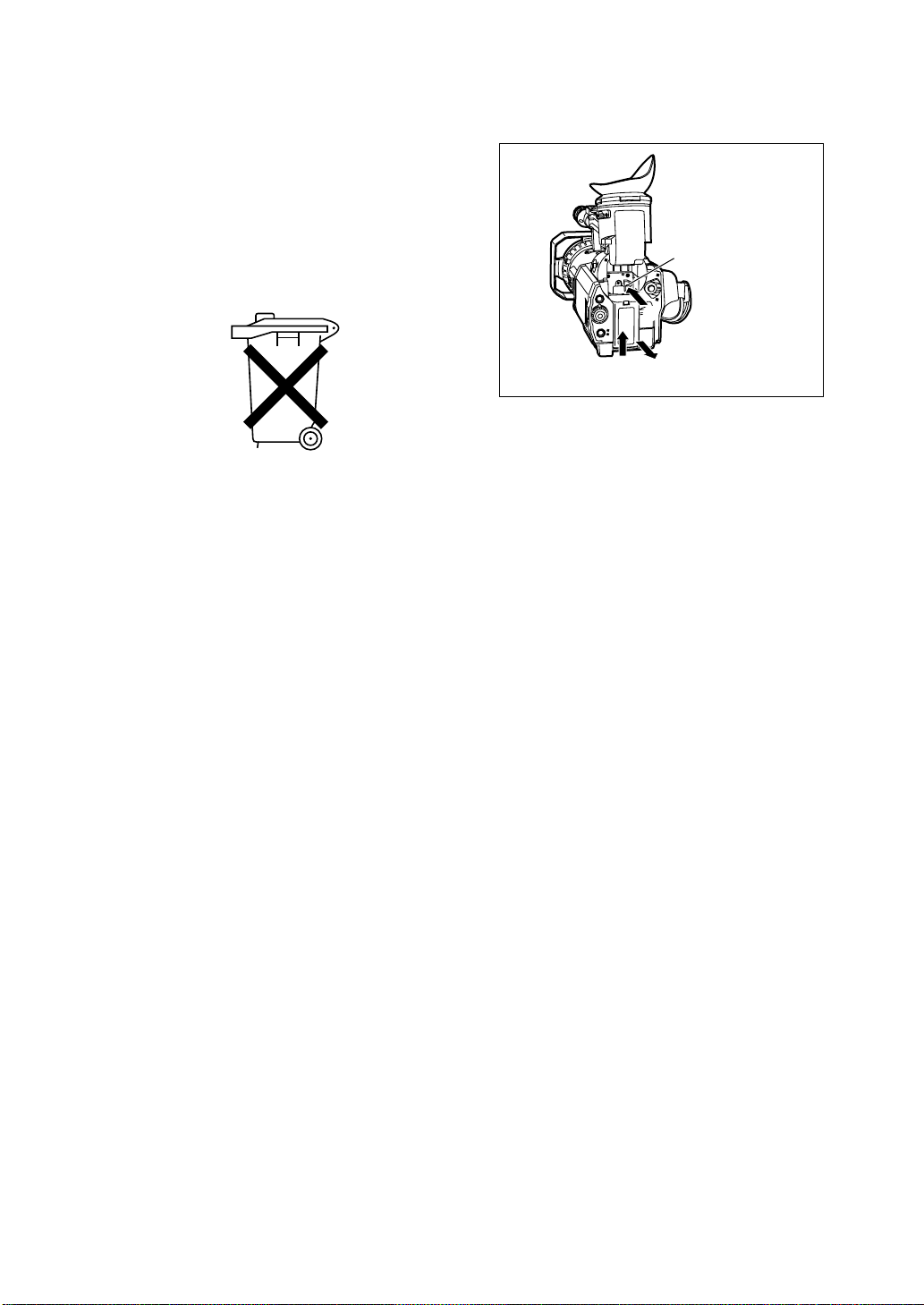
O Batteries are used for the main power source,
memory back-up in the product and remote
controller.
At the end of their useful life, you should not throw
them away.
Instead, hand them in as small chemical waste.
O Voor de primaire voeding en het reservegeheugen
van het apparaat, alsmede voor de
afstandsbediening, wordt gebruik gemaakt van een
batterij.
Wanneer de batterij uitgeput is, mag u deze niet
gewoon weggooien, maar dient u ze als klein
chemisch afval weg te doen.
To remove the battery/
Verwijderen van de batterij
Main Power Battery
Batterij Voor Primaire Voeding
Battery eject button
Batterij verwijderknop
3

Contents
Accessories . . . . . . . . . . . . . . . . . . . . . . . . . .5
Precautions for use . . . . . . . . . . . . . . . . . . . .6
Storage tips . . . . . . . . . . . . . . . . . . . . . . . . . . .8
Parts and their functions . . . . . . . . . . . . . . . .9
Remote control unit . . . . . . . . . . . . . . . . . . .19
Charging the battery . . . . . . . . . . . . . . . . . .20
Mounting the battery . . . . . . . . . . . . . . . . . .21
Supplying power from the AC adapter . . . .21
Cassette tapes . . . . . . . . . . . . . . . . . . . . . . .22
Adjusting the hand strap . . . . . . . . . . . . . . .23
Attaching the shoulder strap . . . . . . . . . . . .23
Mounting the lens hood . . . . . . . . . . . . . . . .23
Viewfinders . . . . . . . . . . . . . . . . . . . . . . . . . .24
Setting the calendar . . . . . . . . . . . . . . . . . . .27
Charging the internal battery . . . . . . . . . . .28
Setting the electronic shutter . . . . . . . . . . .29
White balance and black balance . . . . . . . .31
Adjusting the white balance . . . . . . . . . . . .31
Adjusting the black balance . . . . . . . . . . . .32
ATW (Auto Tracking White) function . . . . .32
Setting the time data . . . . . . . . . . . . . . . . . .33
Setting the user’s bit . . . . . . . . . . . . . . . . . .33
Setting the time code . . . . . . . . . . . . . . . . .34
Scene files . . . . . . . . . . . . . . . . . . . . . . . . . . .35
Changing the scene file settings . . . . . . . . .36
Setting menus . . . . . . . . . . . . . . . . . . . . . . . .38
Operation method . . . . . . . . . . . . . . . . . . . .38
Configuration of setting menus . . . . . . . . . .39
SCENE FILE screen . . . . . . . . . . . . . . . . . .40
CAMERA SETUP screen . . . . . . . . . . . . . .41
SW MODE screen . . . . . . . . . . . . . . . . . . .42
AUTO SW screen . . . . . . . . . . . . . . . . . . . .43
PLAYBACK FUNCTIONS screen . . . . . . . .43
RECORDING SETUP screen . . . . . . . . . . .44
AV IN/OUT SETUP screen . . . . . . . . . . . . .46
DISPLAY SETUP screen . . . . . . . . . . . . . .47
OTHER FUNCTIONS screen . . . . . . . . . . .48
Screen displays . . . . . . . . . . . . . . . . . . . . . .50
Camera mode and VCR mode . . . . . . . . . .50
VCR mode . . . . . . . . . . . . . . . . . . . . . . . . .55
Selecting the display . . . . . . . . . . . . . . . . . .56
Connecting external components . . . . . . . .57
Inputting to and outputting from analog
components . . . . . . . . . . . . . . . . . . . . . . . .57
Inputting to and outputting from digital
components . . . . . . . . . . . . . . . . . . . . . . . .58
Shooting . . . . . . . . . . . . . . . . . . . . . . . . . . . .59
Preparation and inspections . . . . . . . . . . . .59
Regular shooting . . . . . . . . . . . . . . . . . . . .59
REC check . . . . . . . . . . . . . . . . . . . . . . . . .59
Face-to-face shooting . . . . . . . . . . . . . . . . .60
Index recording . . . . . . . . . . . . . . . . . . . . . .60
Using the USER buttons . . . . . . . . . . . . . . .60
Intermittent recording . . . . . . . . . . . . . . . . .60
Backup recording . . . . . . . . . . . . . . . . . . . .61
Progressive shooting . . . . . . . . . . . . . . . . .62
Playback . . . . . . . . . . . . . . . . . . . . . . . . . . . .63
Normal playback . . . . . . . . . . . . . . . . . . . . .63
Tape blank search . . . . . . . . . . . . . . . . . . .63
Variable speed search . . . . . . . . . . . . . . . .63
Index search . . . . . . . . . . . . . . . . . . . . . . . .63
Condensation . . . . . . . . . . . . . . . . . . . . . . . .64
Video heads . . . . . . . . . . . . . . . . . . . . . . . . .64
Troubleshooting (Q&A) . . . . . . . . . . . . . . . .65
Power supply-related problems . . . . . . . . .65
Battery-related problems . . . . . . . . . . . . . .65
Problems during normal video recording . .65
Problems during various kinds of video
recording . . . . . . . . . . . . . . . . . . . . . . . . . . .66
Editing-related problems . . . . . . . . . . . . . . .66
Display-related problems . . . . . . . . . . . . . .66
Playback-related problems (video) . . . . . . .66
Playback-related problems (audio) . . . . . . .67
Other types of problems . . . . . . . . . . . . . . .67
Maintenance . . . . . . . . . . . . . . . . . . . . . . . . .68
Specifications . . . . . . . . . . . . . . . . . . . . . . . .69
O “LEICA” is the registered trademark of Leica Microsystems.
O “DICOMAR” is the registered trademark of Leica Camera AG.
Other model names, company names, products names, etc. are the trademarks and registered
trademarks of the companies concerned.
4
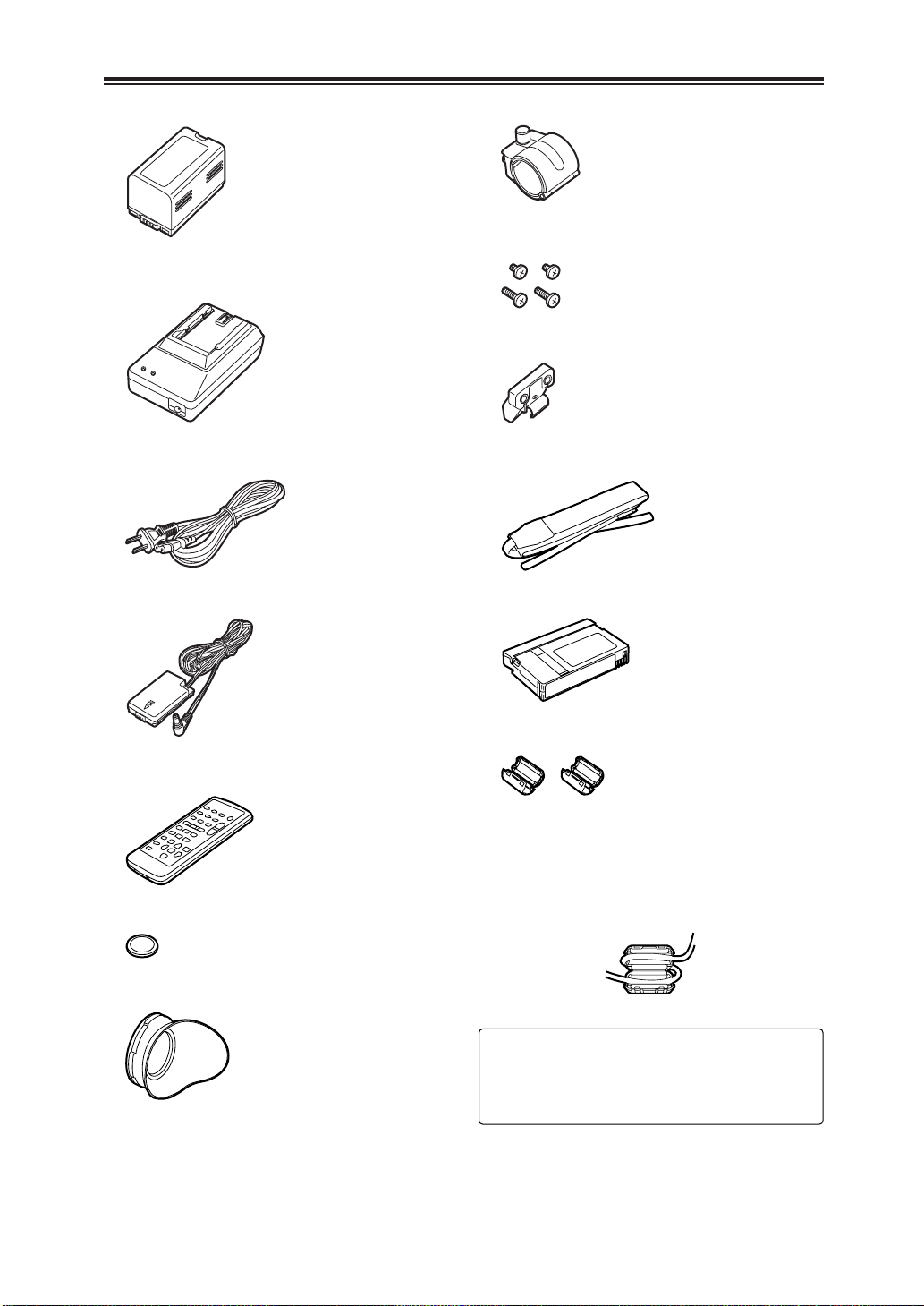
Accessories
OBattery (2)
OAC adapter (2)
OAC cable (K2CA2DA00030)
ODC cable (VEK8722)
OMicrophone holder (VYC0870)
OScrews
6 mm in length (XSB4+6FZ) a2
12 mm in length (XSB4+12FZ) a2
OMicrophone holder adapter (VYC0890)
OShoulder strap (VFC3891)
OCleaning tape (AY-DVMCLC)
O Wireless remote control unit (VFA0402)
OBattery for remote control unit (CR2025)
OEye cup (VMG1458)
OFerrite Cores
Ferrite Cores for DV Interface Cable:
(J0KG00000013)
When the DV Interface cable is to be
connected, attach one Ferrite Core to one
end of the cable and the other one to the
other end.
2 :
Refer to the “OPTIONAL ACCESSORIES”
item (on page 70) for the model numbers of
the battery and AC adapter.
5

Precautions for use
Take care to prevent water from entering
inside the camera recorder when using it in
the rain or snow or at the seashore or in
other similar environments.
O Failure to heed this caution may cause the
camera recorder and/or cassette to
malfunction (possibly leading to irreparable
damage).
Keep the camera recorder away from
equipment (such as TV sets and TV game
machines) that generate magnetic fields.
O When the camera recorder is used on top of or
in the vicinity of a TV set, the radiation of
electromagnetic waves from the set may give
rise to interference in the picture and/or sound.
O The strong magnetic fields generated by
speakers or large motors may ruin the tape
recordings or distort the images.
O The electromagnetic waves from
microcomputers may have an adverse effect
on the camera recorder or give rise to
distortion in the images and sound.
O If the camera recorder is adversely affected by
a component that generates magnetic fields to
such an extent that it can no longer operate
normally, turn off the power and remove the
battery or disconnect the AC adapter from the
power outlet, then re-install the battery or
reconnect the AC adapter to the outlet. After
this, switch the camera recorder’s power back
on.
Do not use the camera recorder near radio
transmitters or high-voltage equipment.
O If the camera recorder is used near a radio
transmitter or high-voltage equipment, the
recorded pictures and/or sound may be
adversely affected.
When using the camera recorder on the
seashore or other similar environment, take
care to ensure that no sand or dust enter
inside the camera recorder.
O Sand and dust may damage the camera
recorder and/or cassette. (Take particular
care when inserting and ejecting the cassette.)
AC adapter and battery
O When the temperature of the battery unit has
risen to an extremely high level or dropped to
an extremely low level or when the battery is
not used for prolonged periods of time and has
become fully discharged, the “CHARGE” lamp
flashes several times, and charging
commences automatically.
O If the “CHARGE” lamp continues to flash even
though the battery temperature is normal,
consult your dealer as a problem may have
developed within the battery or AC adapter.
O When the battery is warm, it takes longer than
usual for the battery to be charged.
O When the AC adapter is used near a radio, the
radio sound may be distorted. Use the
adapter at a distance of at least one meter
from the radio.
O Noise may be heard while the AC adapter is in
use; however, this is normal and not indicative
of any malfunctioning.
When carrying the camera recorder, take
care not to drop it.
O A strong impact may damage the camera
recorder body and render it incapable of
proper operation.
O When carrying the camera recorder, always
use the hand strap or shoulder strap and
handle the camera carefully.
Keep the camera recorder away from
insecticide sprays and volatile liquids.
O If the camera recorder comes into contact with
insecticide sprays or volatile liquids, the
camera body may become deformed or the
surface coating may peel off.
O Ensure that the camera recorder does not
remain in close contact with rubber or plastic
products for prolonged periods of time.
After use, be absolutely sure to remove the
cassette and either remove the camera
recorder’s battery or disconnect its AC cable
from the power outlet.
O If a cassette is left inside the camera recorder,
tape slack may develop and result in damage
to the tape.
O If the battery is left inside the camera recorder
for a prolonged period, its voltage may drop to
such a low level that even after it has been
recharged, it may not be possible to re-use it.
6

Precautions for use
Battery characteristics
This camera recorder uses a rechargeable
lithium-ion battery which produces electrical
energy by means of an internal chemical
reaction. This reaction tends to be easily
affected by the ambient temperature and
humidity, and the period during which the
battery can be effectively used decreases as the
temperature becomes very high or low. The
battery charge will last for only 5 minutes if the
battery is used in an environment where the
temperature is extremely low.
When the battery temperature rises to an
abnormally high level, the protection function is
activated, and it is not possible to use the
battery for a while.
Always remove the battery upon completion
of operation.
Never fail to remove the battery from the
camera recorder. (If it is left in the camera, a
small amount of current will be consumed even
when the camera recorder’s power is off.) If the
battery is left in the camera for a prolonged
period, it will become excessively discharged to
the extent that even after it has been recharged,
it may not be possible to re-use it.
Disposing of the battery
ODispose of the battery when it has reached
the end of its service life.
ODo not dispose of the battery in a fire as it
may explode.
Protect the battery terminals.
Ensure that the battery terminals are free from
dust and foreign matter.
If the battery has been dropped, check that the
battery body and terminals have not been bent
out of shape.
Inserting a deformed battery into the camera
recorder or mounting it in the AC adapter may
result in damage to the camera recorder or AC
adapter.
LCD
OIf the same image or characters are left
displayed for a prolonged period on the LCD
monitor or viewfinder, the image may be
burned onto the screen. If this happens,
keep the power off for several hours to
restore the screen to its original condition.
OThe liquid crystal parts are fabricated using
high-precision technology. The screen has
effective pixels that cover more than 99.99%
of its area, but pixels may be missing or
remain permanently lit in less than 0.01% of
the area. This is neither indicative of
malfunctioning nor does it affect the images
in any way.
OIn locations where the temperature fluctuates
considerably, condensation may form on the
liquid crystal parts of LCD monitor. If this
happens, wipe off the moisture using a soft,
dry cloth.
OIf the temperature of the camera recorder
itself is very low, the LCD monitor may be
slightly darker than usual immediately after
the power has been turned on. Normal
brightness is restored after the internal
temperature has risen.
Do not point the lens or viewfinder’s eyepiece at the sun.
Doing so may damage the internal parts.
Protective caps for the connectors
Keep the protective caps in place over any
connectors which are not being used.
Mounting the camera-recorder on a tripod
The depth of the tripod mounting hole is 5.5
mm.
When mounting this camera recorder on a
tripod, do not force the screw beyond this depth.
Note that if you use any screw other than a 1/420UNC type you could damage the camerarecorder.
Tripod mounting hole
7

Storage tips
When storing the camera recorder, eject the
cassette from the camera recorder and remove
the battery.
Store all components in a location where the
humidity level is low and the temperature is
relatively stable.
Recommended temperature range:
15°C to 25°C
Recommended relative humidity:
40% to 60%
Camera recorder
OWrap the camera recorder in soft cloth to
keep out dust.
Battery
OThe battery’s service life is reduced if the
battery is stored in a location where the
temperature is extremely high or extremely
low.
OIf the battery is stored in a location exposed
to high concentrations of oily vapors and/or
dust, the terminals may corrode or other
problems may develop, possibly resulting in
malfunctioning.
ODo not bring metal objects (such as
necklaces or hairpins) into contact with
the battery terminals. The terminals may
short circuit and generate heat, and
touching them in this condition may cause
severe burns.
OStore the battery only when it is fully
discharged. It is recommended that the
battery be charged once a year when it is
being stored long-term and that it be placed
back in storage after it has been fully
discharged using the camera recorder.
Cassette tapes
OBefore storing a cassette tape, rewind the
tape to its start. If a tape that has been
stopped at some interim point along its length
is stored for six months or more (this period
of time differs depending on the storage
conditions), tape slack will develop. Always
rewind the tape to its start before storing it.
OReturn cassette tapes to their original cases
before storing them. Dust, direct sunlight
(ultraviolet rays), humidity and other such
conditions may damage the tapes. Dust
contains particles of hard mineral substances,
and if dust should enter inside a cassette,
these particles may in turn be transferred to
the heads and other parts, possibly resulting
in their damage. Make a habit of always
returning the cassettes to their original cases.
OFast forward and rewind cassette tapes once
every six months. If tapes are kept wound up
for more than a year, they may become
warped or distorted due to the expansion and
contraction caused by changes in the
temperature and humidity. In addition, layers
of tape may stick together.
ODo not place cassette tapes near matter or
equipment which emits strong magnetic
fields.
OExtremely fine magnetic particles are
contained in the coating of the tape surface,
and it is here that the signals are recorded.
Magnetic necklaces, toys and other such
items may have stronger magnetic fields than
suspected, which may erase recordings or
give rise to noise in the pictures and sound.
8
Parts and their functions
2
783
56 41
O
N
POWER
OFF
E
JE
C
T
=
:
;
<
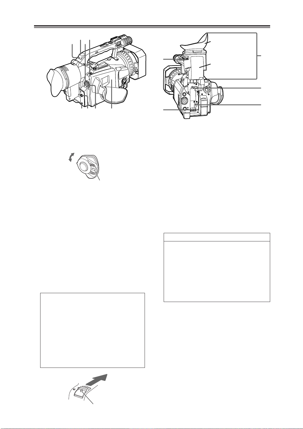
9
(Eye cup)
(Eye-piece)
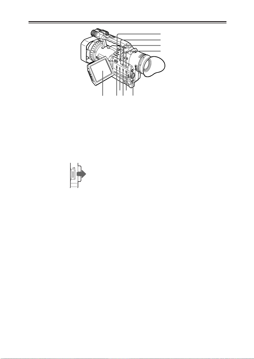
1POWER switch
Move this switch while pressing the lock
release button.
Lock release button
2START/STOP button
When this button is pressed in the camera
mode, shooting can be started or stopped.
Operation is switched between the camera
mode and VCR mode using the
CAMERA/VCR button >.
3EJECT switch
To open the cassette holder, slide this switch
in the direction of the arrow while pressing
the lock release button.
Do not operate the switch while recording is
in progress. The cassette holder will open
but recording will continue, so external light
and/or dust will adversely affect the tape.
O
Do not insert or eject the cassette tape
holding onto the cassette holder alone.
Insert or eject the tape with the camera
recorder placed on a flat and stable
surface or, alternatively, support the
camera recorder with both hands so that it
will be kept in a stable condition even if
the cassette holder is opened.
O
Close the cassette holder after
ensuring that the cassette mechanism
has completed the eject operation.
4Cassette holder
5CAM REMOTE jack (2.5 mm mini jack)
The remote control unit is connected to this
jack to enable zooming and record start/stop
to be initiated by remote control.
6PHONES jack (3.5 mm stereo mini jack)
The headphones are connected to this jack to
monitor the sound.
7Remote control sensor (rear)
8Tally lamp (rear)
This lights or blinks depending on the status
of the camera recorder.
Lights: While shooting is in progress.
Blinks:
O When a remote control operation has been received
(about 8 blinks per second)
O When shooting is commenced
(about 8 blinks per second)
O When the tape has come to the end
(about 4 blinks per second)
O When a problem has arisen in the tape transport
system (about 4 blinks per seconds)
O When there is little tape or battery charge remaining
(once a second)
The settings for causing the tally lamp to flash
are performed using the REC LAMP item on
the setting menu OTHER FUNCTIONS
screen. (See page 48)
9Viewfinder
:Diopter adjustment dial
This is adjusted in such a way that the
viewfinder screen comes into sharp focus.
Lock release button
;Power socket
<DC INPUT connector (7.9V)
=Battery eject button
9
B
A
Parts and their functions
>?@
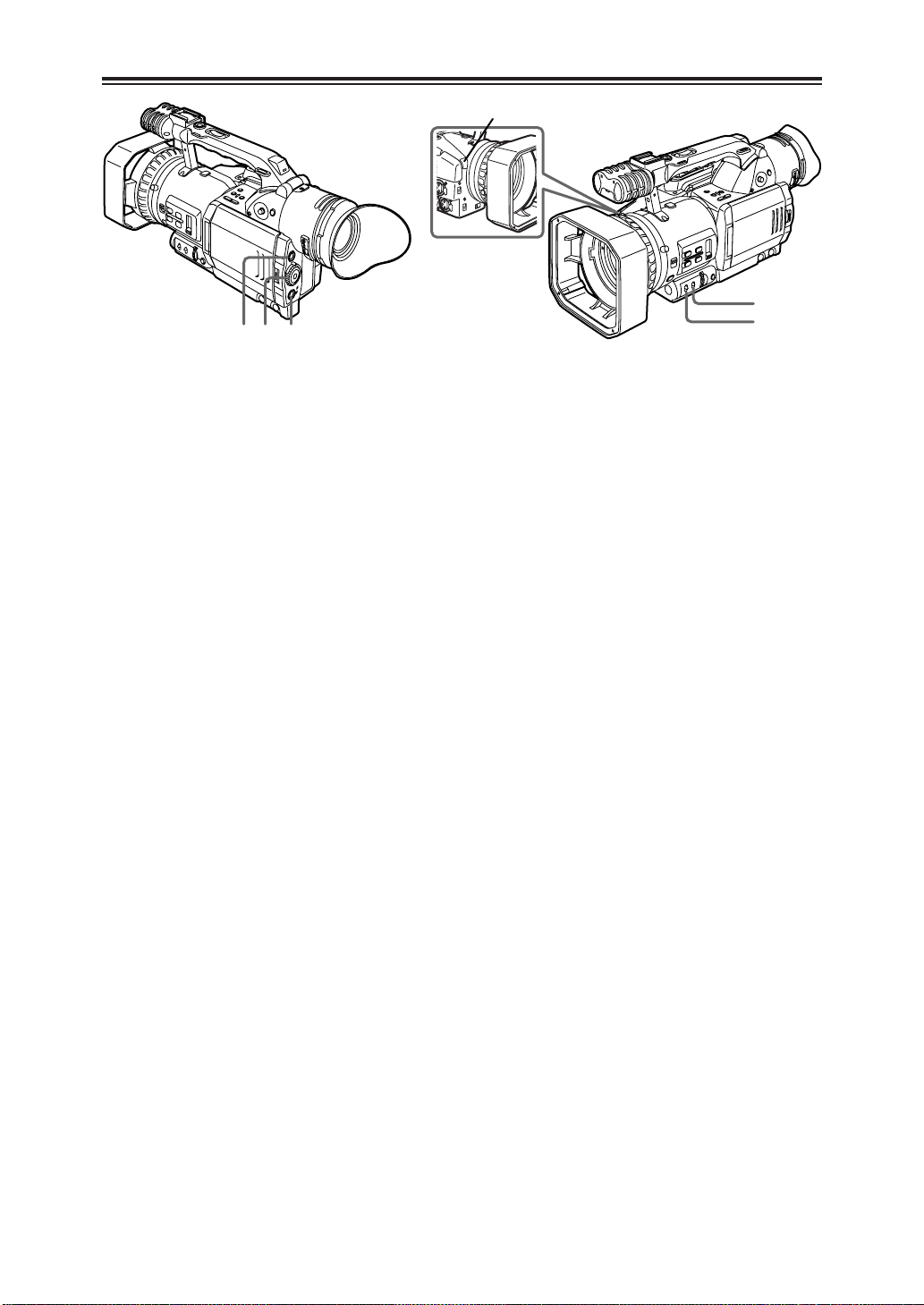
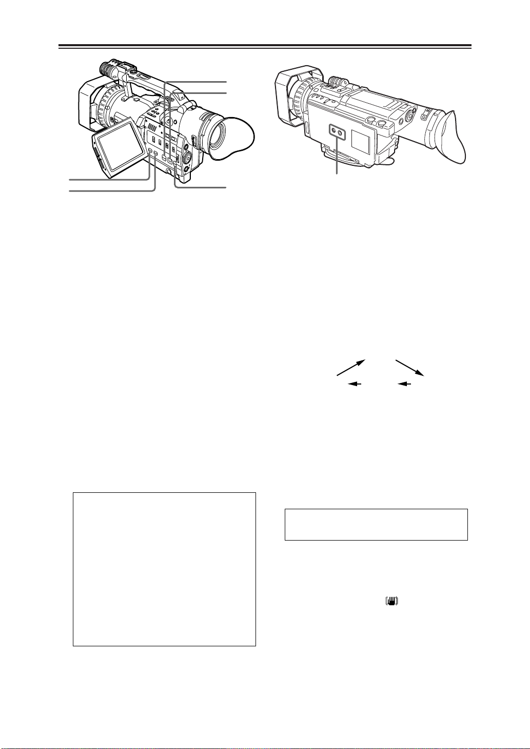
White balance sensor
>CAMERA/VCR button and lamp
Each time this button is pressed, the
operation mode is switched between the
camera mode and VCR mode, and the lamp
of the selected mode lights.
Select the camera mode for shooting.
Select the VCR mode to check the tape
contents or input and record video signals
from an external source.
?Scene file dial
This is used to select the scene files. (See
page 35)
conditions are stored in the positions of this
dial.
be instantly loaded using the dial.
@EVF DTL/END SEARCH button
When this button is pressed in the camera
mode, the outlines of the images in the
viewfinder and on the LCD monitor are
accentuated, and focusing is thereby facilitated.
“EVF DTL ON” will also be displayed on the
center of the screen for approximately 2
seconds. However, the images which are
recorded at this time will be the regular images
whose outlines are not accentuated.
Pressing the button once again will return the
unit to its original status. “EVF DTL OFF” will
also be displayed on the center of the screen
for approximately 2 seconds.
When this button is pressed in the VCR
mode, the unrecorded blanks on the video
tape are searched, and the still picture mode
is established about one second before an
unrecorded blank.
The part which was shot last can also be
searched using the END SEARCH item
setting on the setting menu PLAYBACK
FUNCTIONS screen. (See page 43)
OWhen one tape is replaced with another,
the part which was shot last cannot be
searched using this button.
OIf no signals have been recorded on the
tape, the tape stops at the tape end.
Settings tailored to various shooting
During shooting, the necessary file can
OThis function may not operate properly if
there is an unrecorded blank near the tape
start or at a point along the tape.
OBefore proceeding with recording, check
the picture which has been searched.
AGAIN switch
When the camera screen is too dark, change
the setting of this switch to boost the gain and
make the screen brighter. The M and H gain
values are set using the MID GAIN item and
HIGH GAIN item on the setting menu SW
MODE screen. (See page 42)
L:The switch is normally kept at this
position. (0 dB)
M:The gain of the camera video amplifier is
boosted. (Factory setting: 6 dB)
H:The gain of the camera video amplifier is
further boosted. (Factory setting: 12 dB)
BWHITE BAL switch
This is used to set the white balance.
A or B:
The white balance value adjusted by the
AWB button C is stored in the memory.
PRST (preset):
Set the switch to this position in cases
where, for instance, there is no time to
adjust the white balance.
The 3200K and 5600K white balance
values are stored in the memory.
Press the AWB button to switch between
the two values.
OThe ATW (Auto Tracking White) function
can be allocated to the A, B or PRST
position using the ATW item on the setting
menu SW MODE screen. (See page 42)
OWhat kind of light source is being used
during shooting is determined by the white
balance sensor.
Do not block the front of the white balance
sensor with your hand or any other object
during shooting or the ATW function will
not operate properly.
10

Parts and their functions
F
I
H
G
D
E
C
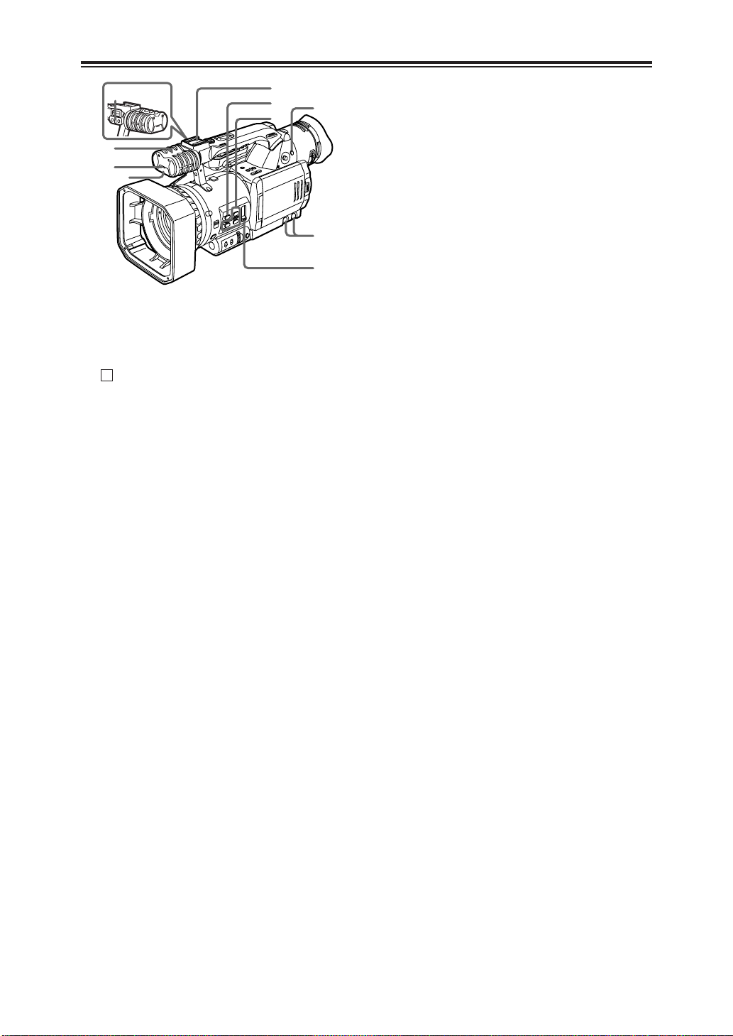
Zoom ring pin
CAWB button
When this button is pressed while the WHITE
BAL switch B is set to the A or B position,
the white balance is automatically adjusted,
and the white balance value is stored in the
memory.
If this button is then held down, the black
balance is adjusted.
When this button is pressed while the WHITE
BAL switch B is set to the PRST position, the
current white balance value is displayed.
When the AWB button is pressed again, the
3200K and 5600K white balance values are
selected alternately.
OWhile recording is in progress, the black
balance cannot be adjusted.
DIRIS button
Each time this button is pressed, the method
of adjusting the lens iris is switched between
the auto mode and manual mode.
<Note>
The maximum aperture of the lens iris of this
unit is F1.6 when the lens is at the full zoom
(W) position and F2.8 at the full TELE (T)
position.
The display shown for the F-number in the
viewfinder and/or LCD monitor is “OPEN”
when the lens is at the full zoom (W) position
and “F2.8” or “OPEN” when the lens is at the
full TELE (T) position.
EIRIS dial
This is used to adjust the lens iris.
When the IRIS button D is set to the manual
mode, this dial is used to adjust the lens iris.
Even in the auto mode, the lens iris can be
adjusted using this dial.
OThe direction in which the IRIS dial is
turned and iris control can be set using the
IRIS DIAL item on the setting menu SW
MODE screen. (See page 42)
FFOCUS switch
This is used to select the method of
controlling the focus.
A (AUTO):
Auto focus mode
M (MANUAL):
Manual focus mode
The focus ring H is controlled manually to
adjust the focus.
:
∞
After the focal length has been set to
infinity, the manual focus mode is
established. Even if the FOCUS switch is
set to the
(MANUAL) position.
OEven when the manual focus mode is
established, the AUTO button J setting
takes priority if it is pressed.
OIf flicker occurs, the auto focus control may
not be exercised properly, so select a
shutter speed suited to the lighting. (See
page 29)
OThe focus assist mode is established if the
auto focus mode is selected in the
progressive mode or slow shutter mode.
Focusing can be conducted more precisely
than in the manual focus mode, but it takes
slightly longer to exercise focus control
compared with the regular auto focus
mode.
GPUSH AUTO button
While this button is pressed with the FOCUS
switch set to the M (MANUAL) position, the
auto focus mode is established, and the focus
is adjusted.
position, it will return to the M
∞
HFocus ring
IZoom ring
If the zoom ring pin is not required, fit it into
the threaded hole under the handle so that it
will not be lost.
11
P
M
K
O
L
J
Q
S
R
N
Parts and their functions
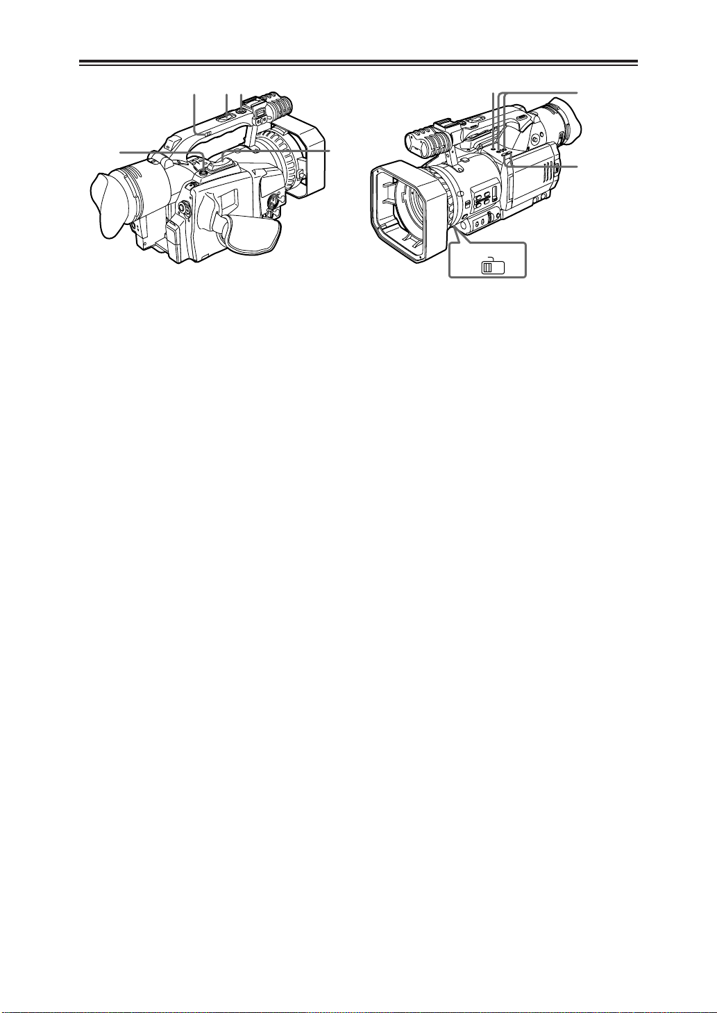
JAUTO button
When the AUTO button is pressed, the
operation mode which was set on the setting
menu AUTO SW screen is established, and
“ ” appears in the upper part of the
A
viewfinder and LCD monitor.
On the setting menu AUTO SW screen, the
mode of the operation to be performed
automatically (auto iris, auto gain control,
auto tracking white or auto focus) when the
AUTO button is pressed is set.
(See page 43)
The setting is released when the button is
pressed again.
KUSER1, USER2 and USER3 buttons
One of 11 functions can be allocated in turn
to each of the USER1, USER2 and USER3
buttons.
In accordance with the subject concerned,
the shooting conditions can be instantly
selected or fade effects can be added to the
images.
For details, refer to the USER1 item, USER2
item and USER3 item (page 42) on the
setting menu SW MODE screen.
LND FILTER switch
This is used to select the ND filter (for
adjusting the light quantity) to be used.
OFF: The ND filter is not used.
1/8 : The light quantity is reduced to about
one eighth.
1/64: The light quantity is reduced to about
one sixty-fourth.
MAUDIO controls
These are used to adjust the recording level
of the audio signals which have been input to
the built-in microphone P and INPUT 1 and 2
connectors Y.
Adjust the recording level of the audio signals
using these controls, irrespective of the
setting selected for the MIC ALC item on the
RECORDING SETUP screen of the setting
menu (page 44).
It is recommended that the centre position
normally be selected for use.
OThey cannot be used to adjust the audio
signals which have been input to the
AUDIO IN/OUT CH1 and CH2 connectors
V.
NLight shoe
A video light, for instance, is attached to this
shoe.
OMicrophone shoe
The accessory microphone holder is attached
to this shoe so that a microphone (optional
accessory), etc. can be mounted. (See page
57)
PMicrophone (built-in, stereo)
Do not apply a strong load from an external
source to this microphone as it may damage
the microphone.
QTally lamp (front)
Refer to the details on the tally lamp (rear) 8.
RRemote control sensor (front)
SMENU button
When this button is pressed, the menu mode
is established, and the setting menu screen is
displayed in the viewfinder and on the LCD
monitor.
When it is pressed again, the menu mode is
released.
12

Parts and their functions
U
Z
X
Y
W
V
T
[In the camera mode]
“5” :
When the lever is tilted in the “5”
direction in the shooting pause mode, the
tape is played back in the “5” direction
at 1a speed while the lever is tilted.
“6” :
When the lever is tilted in the “6”
direction in the shooting pause mode, the
tape is played back in the “6” direction
at 1a speed while the lever is tilted.
OThe scenes shot up until now can be
checked in the shooting pause mode.
TOPERATION lever
This lever is used to operate the VCR and
conduct the menu operations.
[In the VCR mode]
“1” :
When the lever is tilted in the “1” direction
in the stop mode, the tape is played back.
When it is tilted in the same direction
during playback, the variable speed search
mode (see page 63) is established, and the
tape is played back at the 1a speed.
(Sound is not played back.)
“5” :
When the lever is tilted in the “5”
direction in the stop mode, the tape is fast
forwarded.
When it is tilted in the same direction
during playback, the tape is cued at 10a
speed.
“6” :
When the lever is tilted in the “6”
direction in the stop mode, the tape is
rewound.
When it is tilted in the same direction
during playback, the tape is reviewed at
10a speed.
“$” :
When the lever is tilted in the “$” direction,
the tape is stopped.
“;” :
When the lever is pressed during playback,
the tape is set to the pause (temporary
stop) mode.
[In the menu mode]
“3” :
When the lever is tilted in the “3” direction,
the items displayed on the menu screen
are moved upward.
“4” :
When the lever is tilted in the “4” direction,
the items displayed on the menu screen
are moved downward.
“;” :
Press the lever to change a setting.
US-VIDEO IN/OUT connector
This is the S-video input/output connector.
VAUDIO IN/OUT CH1 and CH2 connectors
(pin jacks)
These are the input/output connectors for the
audio signals.
WVIDEO IN/OUT connector
(pin jack)
This is the input/output connector for the
video signals.
XDV connector
An IEEE1394 (4-pin) cable (optional
accessory) is connected here.
Video signals, audio signals or time codes,
for instance, can be input and output digitally.
YINPUT 1, 2 connectors (XLR, 3-pin)
External microphones or audio components
are connected here.
ZINPUT 1/2 switch
This is used to switch the audio input signals
which are connected to the INPUT 1 and 2
connectors.
LINE:
The audio input signals from the audio
component serving as the line input are
selected; their input level is 0 dBu.
MIC:
The audio input signals from the external
microphone(s) are selected; their input
level is –50 dBu.
The input level can be changed to –60 dBu
using the MIC GAIN 1 and MIC GAIN 2
items on the setting menu RECORDING
SETUP screen. (See page 44)
13
`
]
_
^
\
b
c
ZOOM
SERVO MANU
[
a
Parts and their functions
[ZOOM switch
This is used to select motor-driven zoom
operations or manual zoom operations.
SERVO:
For motor-driven zoom operations
(At this position, do not attempt to perform
manual zoom operations or malfunctioning
may result.)
MANU:
For manual zoom operations
\START/STOP button (on the handle)
When this button is pressed in the camera
mode, shooting start or stop is selected.
The camera mode and VCR mode are
switched using the CAMERA/VCR button >.
]REC CHECK button
When this button is pressed in the shooting
pause mode, the picture and sound
immediately before shooting was stopped are
played back for several seconds, and the
shooting pause mode is established at the
original position on the tape.
^Zoom button
When the ZOOM switch is at the SERVO
position, motor-driven zoom operations are
performed.
When this button is pressed lightly, zoom
operations are performed at a low speed;
when it is pressed with force, they are
performed at a high speed.
_Zoom button (on the handle)
`HANDLE ZOOM switch
This switch is used to select one of the three
speeds for the zoom operations conducted
using the zoom button _ on the handle.
The speed is set using the HANDLE ZOOM
item on the setting menu SW MODE screen.
(See page 42)
aAUDIO DUB button
When the pause status is established in the
VCR mode and this button is pressed, the
mode in which audio dubbing can be started
is established.
Press “;” of the OPERATION lever T to
record the sound. To stop the recording, tilt
the OPERATION lever in the “$” direction.
The audio input used for audio dubbing is set
using the A DUB INPUT item on the setting
menu AV IN/OUT SETUP screen. (See page
46)
OBefore proceeding with the audio dubbing,
select “32K (12 bit)” as the AUDIO REC
item setting on the setting menu
RECORDING SETUP screen and then
start shooting. (See page 44)
bVCR REC buttons
When these two buttons are pressed at the
same time in the stop status of the VCR
mode, the video signals from the connected
component are recorded.
When they are pressed at the same time in
the playback pause status of the VCR mode,
the recording standby status is established.
Each time “;” of the OPERATION lever T is
pressed, the status alternates between
recording and recording standby.
To stop recording, tilt the OPERATION lever
in the “$” direction.
OBefore proceeding to record, check that the
video signals have been input.
cAUDIO MON/VAR buttons
These buttons are used to adjust the volume
at which the sound is to be output from the
internal speaker f or PHONES jack 6.
The playback direction and playback speed
are changed in the variable speed search
mode. (See page 63)
When these buttons are pressed in the pause
status, the tape is played back frame by
frame.
14
Parts and their functions
f
e
l
m
k
j
i
h
g
d
OPEN
dOPEN button
Press the OPEN button in the direction of the
arrow to open the LCD monitor e.
When the LCD monitor is opened, the image
on the viewfinder switches to the LCD
monitor.
The image can be switched using the EVF
MODE item on the setting menu DISPLAY
SETUP screen. (See page 48)
eLCD monitor
fInternal speaker
gRESET button
If the camera recorder cannot be operated
even though its power is on or some other
form of trouble has occurred, use a pointed
object to press the RESET button. This will
reset the system microcomputer.
Even after resetting has been initiated, the
entered setting menu values and memory
contents will not be erased.
Refrain from pressing the RESET button
when the camera recorder is operating
properly.
hSHUTTER button
Press this button to change the shutter
speed.
After pressing this button, press the SPEED
SEL button i to select the shutter speed.
(See page 29)
This button cannot be operated in the slow
shutter mode.
iSPEED SEL button
After pressing the SHUTTER button h or
when the slow shutter mode is established,
press this button to select the shutter speed.
(See page 29)
jCH1 SELECT switch
This switch is used to select the input signals
which are to be recorded on the audio
channel 1 track.
INT (L):
Audio signals of the left (L) channel of the
internal microphone
INPUT1:
Audio signals which are input to the INPUT
1 connector
INPUT2:
Audio signals which are input to the INPUT
2 connector
kCH2 SELECT switch
This switch is used to select the input signals
which are to be recorded on the audio
channel 2 track.
INT (R):
Audio signals of the right (R) channel of the
internal microphone
INPUT2:
Audio signals which are input to the INPUT
2 connector
lINPUT 1 switch (MIC POWER +48 V)
When this switch is set to ON, +48 V power
(power supply for the phantom mic) is
supplied to the INPUT 1 connector.
mINPUT 2 switch (MIC POWER +48 V)
When this switch is set to ON, +48 V power
(power supply for the phantom mic) is
supplied to the INPUT 2 connector.
15
o
p
q
r
n
Parts and their functions
s
OFF
ZEBRA 1ZEBRA 2
nCOUNTER RESET button
This button is used to reset the counter value
on the counter display and the memory
counter value to zero.
It cannot reset the time code or user’s bit.
oCOUNTER button
This button is used to select what data is to
be displayed on the counter display which is
in the viewfinder and on the LCD monitor.
Each time it is pressed, the data to be
displayed changes.
COUNTER:
The counter value is displayed.
M COUNTER:
The counter value in the memory stop
mode is displayed.
TC : The time code is displayed.
UB : The user’s bit is displayed.
FR : The frame rate information (25P) when
shooting is to be performed in the
progressive mode is displayed.
Blank display :
No data is displayed.
Memory stop mode
The memory stop mode is established when the
display is switched to M COUNTER using the
COUNTER button.
1 Switch the display to M COUNTER, and press the
COUNTER RESET button n at any tape position to
reset the counter value.
2 Proceed with playback or shooting.
3 Establish the VCR mode using the CAMERA/VCR
button.
4 When the tape is now rewound or fast forwarded, it
stops travelling automatically near where the counter
value was reset.
O If the counter value is reset at the OUT point during
audio dubbing, audio dubbing can be stopped in the
memory stop mode.
pMODE CHK button
When this button is pressed, the current
camera status setting can be checked in the
viewfinder and on the LCD monitor.
qZEBRA button
When this button is pressed in camera mode,
a zebra pattern or marker appears in the
viewfinder and on the LCD monitor, enabling
the brightness of the subject to be checked.
Each time it is pressed, the display changes
as shown below.
Marker
The level of each zebra pattern can be set
using the ZEBRA DETECT 1 item and
ZEBRA DETECT 2 item on the setting menu
DISPLAY SETUP screen.
The zebra pattern which has been set is
displayed as a percentage for the prescribed
time (approx. 2 seconds).
Display of the marker can also be switched
ON/OFF with the MARKER item on this
screen. (See page 47)
Zebra pattern
Parts that may be whitened out due to overexposure
are displayed using a striped pattern.
rOIS button
This button is used to set camera shake
compensation to ON or OFF. When the
compensation is ON, appears in the
viewfinder and on the LCD monitor.
Select ON or OFF to suit the shooting
conditions.
When shooting using a tripod, the OFF
setting is recommended.
16
sTripod mounting hole
OSD
COUNTER
RESET TITLE
STILL ADV
PAUSE
STILL ADV
INDEX
SELECT
STORE
OFF/ON
P.B.DIGITAL
VAR.
SEARCH
– VOL +
PB.
ZOOM
MENU
SET
ITEM
STOP INDEX
MULTI/
P-IN-P
REC A.DUB
PLAYC/REW FF/
B
ZOOM
DATE/
TIME
PHOTO
SHOT
START/
STOP
1
5
7
6
2
3
4
8
Parts and their functions
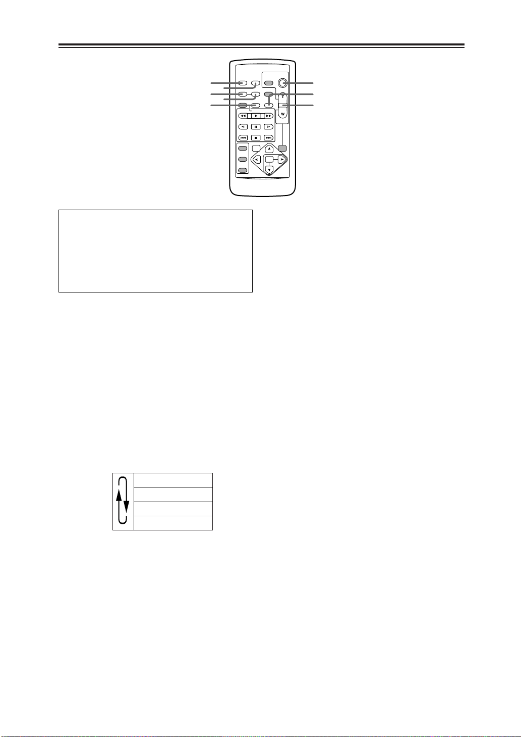
Remote control unit
The buttons listed below are for functions
which are not featured on the camera
recorder.
OPHOTO SHOT OTITLE
OMULTI/P-IN-P OSELECT
OSTORE OOFF/ON
OPB. ZOOM O N
1OSD button
When this button is pressed, the information
displayed in the viewfinder and on the LCD
monitor is added to the video signals, and it
can be displayed on a TV monitor as well.
When it is pressed again, the display on the
TV monitor is cleared.
2DATE/TIME button
When this button is pressed, the shooting
date (year/month/day) and/or time are
displayed in the viewfinder and on the LCD
monitor.
Each time it is pressed, the display is
switched in the sequence shown below.
No display
Time display
Date display
Time and date display
5COUNTER button
This button has the same function as the
COUNTER button on the camera recorder
body.
6COUNTER RESET button
This button has the same function as the
COUNTER RESET button on the camera
recorder body.
7REC button
When this button is pressed together with the
PLAY button while operation is stopped in the
VCR mode, the video signals from the
connected component are recorded.
When it is pressed together with the PLAY
button during playback pause in the VCR
mode, the recording standby status is
established.
Each time the PAUSE (;) button is pressed,
the status is switched between recording and
recording standby.
To stop recording, press the STOP ($)
button.
8A. DUB button
This button has the same function as the
AUDIO DUB button on the camera recorder
body.
3START/STOP button
This button has the same function as the
START/STOP button on the camera recorder
body.
4ZOOM/VOL buttons
During shooting, these buttons are used to
conduct motor-driven zoom operations.
The zoom speed is fixed at the medium
speed.
During tape playback, they are used to adjust
the volume at which the sound is to be output
from the internal speaker and PHONES jack.
17

Parts and their functions
OSD
COUNTER
RESET TITLE
STILL ADV
PAUSE
STILL ADV
INDEX
SELECT
STORE
OFF/ON
P.B.DIGITAL
VAR.
SEARCH
– VOL +
PB.
ZOOM
MENU
SET
ITEM
STOP INDEX
MULTI/
P-IN-P
REC A.DUB
PLAYC/REW FF/
B
ZOOM
DATE/
TIME
PHOTO
SHOT
START/
STOP
9
;
:
9VCR operation buttons
C/REW button (6)
This button has the same function as the
OPERATION lever on the camera recorder
body.
FF/B button (5)
This button has the same function as the
OPERATION lever on the camera recorder
body.
PLAY button (1)
When this button is pressed in the VCR
mode, the tape is played back.
When it pressed together with the REC
button, the video signals from the
connected component are recorded.
STILL ADV buttons (E, D)
When either button is pressed during tape
playback, slow-motion playback results.
When it is pressed in the pause status,
frame advance playback results.
(E in the reverse direction, D in the
forward direction)
INDEX buttons (:, 9)
When either button is pressed during tape
playback, the start of a recorded section is
searched.
(: in the reverse direction, 9 in the
forward direction)
PAUSE button (;)
This button has the same function as the
OPERATION lever on the camera recorder
body.
STOP button ($)
This button has the same function as the
OPERATION lever on the camera recorder
body.
18
:VAR. SEARCH button
When this button is pressed during playback,
the variable search mode is established, and
“1a” is displayed in the viewfinder and on the
LCD monitor. When the “V” or “B” button
among the SET buttons ; is pressed, the
playback speed is changed.
Each time the “V” or “B” button is pressed,
the playback speed is changed by one setting
in the following sequence: 1/5a (or 1/3a in
the LP mode), 1a, 2a, 5a, 10a and 20a.
Use the “V” button to change the speed in
the forward direction and the “B” button to
change it in the reverse direction.
;SET buttons
MENU button:
This button has the same function as the
MENU button on the camera recorder
body.
“V” button:
When this is pressed in the menu mode,
the items displayed on the menu screen
are moved upward.
When it is pressed in the search mode, the
speed is changed in the forward direction.
“B” button:
When this is pressed in the menu mode,
the items displayed on the menu screen
are moved downward.
When it is pressed in the search mode, the
speed is changed in the reverse direction.
“M” button:
Press this in the menu mode to change
settings.
Remote control unit
OSD
COUNTER
RESET TITLE
STILL ADV
PAUSE
STILL ADV
INDEX
SELECT
STORE
OFF/ON
P.B.DIGITAL
VAR.
SEARCH
– VOL +
PB.
ZOOM
MENU
SET
ITEM
STOP INDEX
MULTI/
P-IN-P
REC A.DUB
PLAYC/REW FF/
B
ZOOM
DATE/
TIME
PHOTO
SHOT
START/
STOP
VCR 2 VCR 1
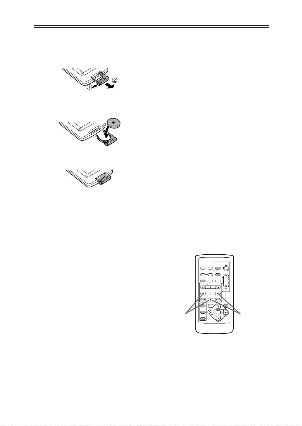
Installing the battery
1
While pushing the knob in the direction of the
arrow, pull out the holder.
2
Insert the battery with the “+” marking face
up.
3
Return the holder to its original position.
OWhen the battery (CR2025) has completely
run down, replace it with a new one. (The
battery life is about one year although it
depends on how often the remote control unit
is used.) If the remote control unit is
operated near the camera recorder’s remote
control sensor and the camera recorder fails
to operate, it means that the battery has run
down.
OKeep batteries out of the reach of small
children.
Remote control unit settings
In order to prevent mistakes made in operations
performed using remote control when two
camera recorders are operated at the same
time, the operation buttons on the camera
recorder and accessory wireless remote control
unit can be set to work for “VCR1” applications
and for “VCR2” applications.
Setting method
OWireless remote control unit
When the STOP ($) and STILL ADV (D)
buttons among the VCR operation buttons
are pressed at the same time, the operation
buttons on the remote control unit are set to
be used for VCR1.
Similarly, when the STOP ($) and STILL ADV
(E) buttons among the VCR operation
buttons are pressed at the same time, the
operation buttons on the remote control unit
are set to be used for VCR2.
When the battery in the remote control unit
has been replaced, the operation buttons are
set to be used for VCR1.
OCamera recorder body
Set VCR1 and VCR2 using the REMOTE
item on the setting menu OTHER
FUNCTIONS screen. (See page 48)
If the camera recorder body and remote control
unit settings are at variance, “REMOTE” in red
letters lights up and is displayed in the
viewfinder and on the LCD monitor.
19
Charging the battery
POWER
CHARGE
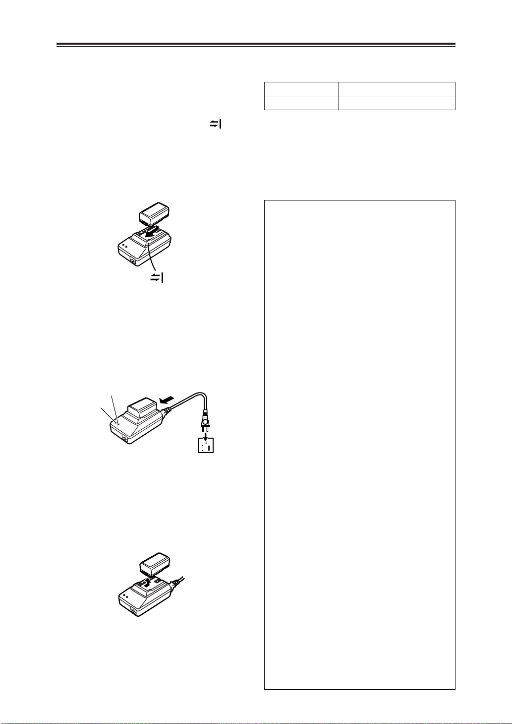
Fully charge the battery using the AC adapter
before use.
It is recommended that a spare battery be kept
on hand just in case it is needed.
1
Place the battery flat along the mark
on the AC adapter, and slide it into
position.
OIf the DC cable is connected to the AC
adapter, disconnect it before proceeding.
The battery cannot be charged if this cable
is connected.
Connect the AC cable to the power outlet.
2
OThe “POWER” lamp and “CHARGE” lamp
on the AC adapter light up, and charging
commences.
OIf the “CHARGE” lamp fails to light when
the battery has been mounted, re-mount
the battery.
Upon completion of the charging, the
3
“CHARGE” lamp on the AC adapter goes
off.
Slide the battery out of position and
4
remove it.
Charging and recording times of accessory
battery
Charging time Continuous recording time
Approx. 120 minutes Approx. 90 (80) minutes
O The table above gives the approximate durations. The
figure in parentheses is the duration when the LCD monitor
is used.
O The durations in the above table apply when the ambient
temperature is 20°C and the relative humidity is 60%.
Charging may take longer at other temperature and
humidity levels.
O Do not bring metal objects (such as
necklaces or hairpins) into contact with
the battery terminals. The terminals
may short circuit and generate heat, and
touching them in this condition may
cause severe burns.
O The battery heats up during operation and
during charging, as does the camera
recorder body.
O If recording and stop operations are
repeated more than is necessary, the
recording time will be less than the values
given in the above table.
O Store the battery only when it is fully
discharged. It is recommended that the
battery be charged once a year when it is
being stored long-term and that it be placed
back in storage after it has been fully
discharged using the camera recorder.
O When the temperature of the battery unit
has risen to an extremely high level or
dropped to an extremely low level or when
the battery is not used for prolonged
periods of time has become fully
discharged, the “CHARGE” lamp flashes
several times, and charging commences
automatically.
O If the “CHARGE” lamp continues to flash
even though the battery temperature is
normal, consult your dealer as a problem
may have developed within the battery or
AC adapter.
O When the battery is warm, it takes longer
than usual for the battery to be charged.
O When the AC adapter is used near a radio,
the radio sound may be distorted. Use the
adapter at a distance of at least one meter
from the radio.
O Noise may be heard while the AC adapter
is in use; however, this is normal and not
indicative of any malfunctioning.
O The battery cannot be charged while
supplying power from the AC adapter to the
camera recorder.
20
Mounting the battery
1
2
3
1
3
4
2
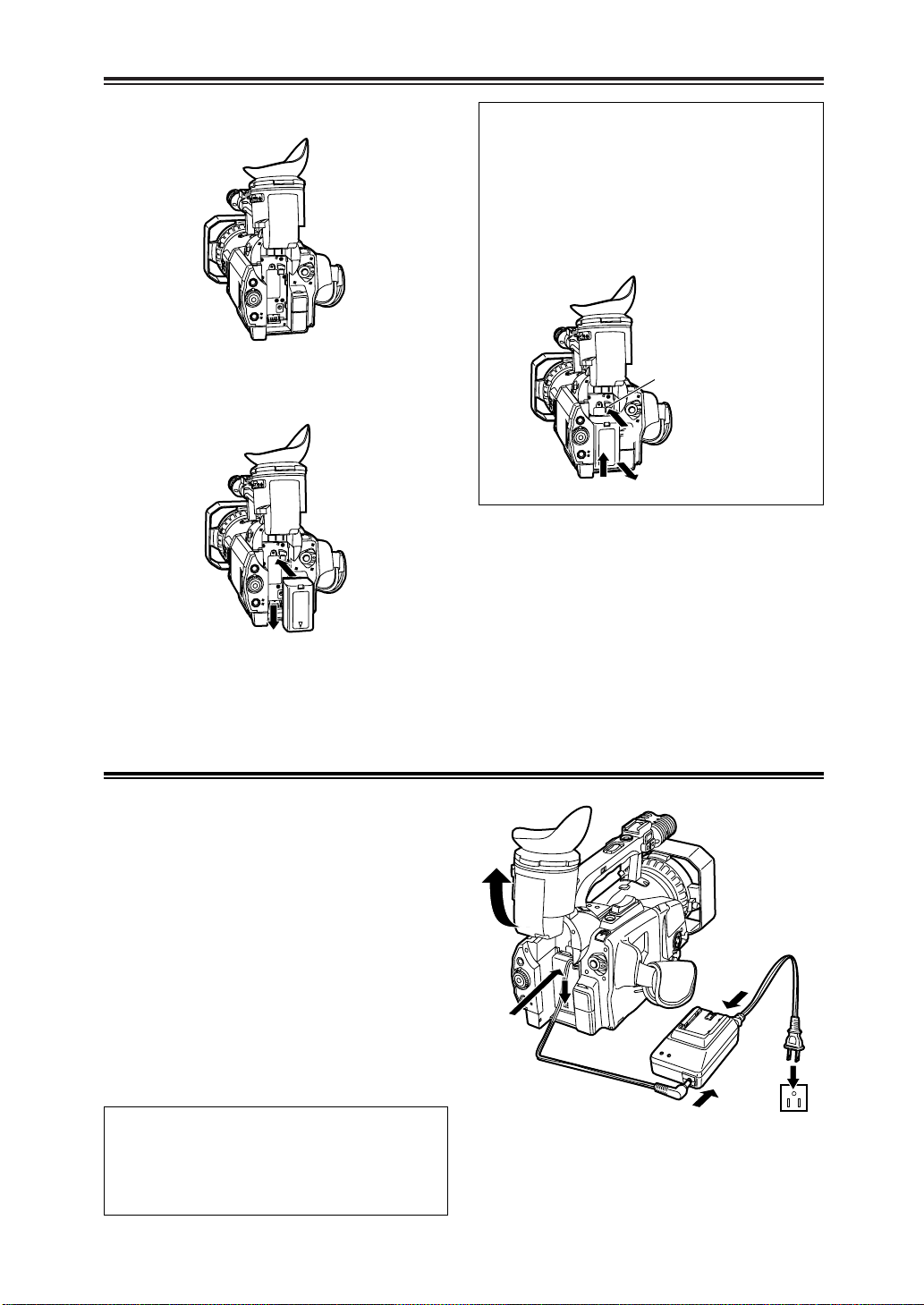
Raise the viewfinder.
1
Push the battery straight in, and slide it
2
downward until it clicks into position.
Removing the battery
While pressing the battery eject button, slide
the battery upward to remove.
O Set the POWER switch to OFF, and check
that the CAMERA/VCR lamp has gone off
before removing the battery.
O Support the battery with your hand to
ensure that it will not drop.
Battery eject button
Return the viewfinder to its original
3
position.
Supplying power from the AC adapter
Raise the viewfinder.
1
Push the battery-type connector on the
2
DC cable straight in, and slide it
downward until it clicks into position.
Connect the DC cable to the AC adapter.
3
Connect the AC cable to the power outlet.
4
Return the viewfinder to its original
5
position.
Connect the AC adapter correctly as
shown in the figure.
O The battery cannot be charged while
supplying power from the AC adapter to the
camera recorder.
21
PUSH CLOSE
PUSH CLOSE
Cassette tapes
REC
SAVE
E
JEC
T
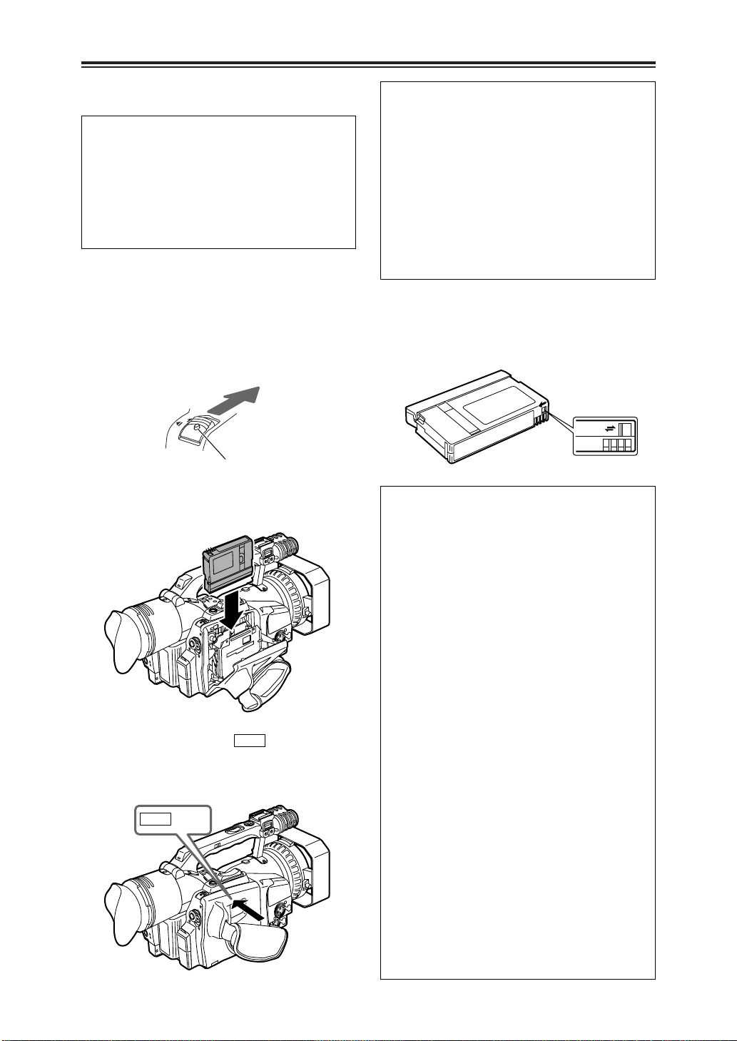
Inserting a cassette tape
Do not insert or eject a cassette tape by
taking hold of the cassette holder alone.
Insert or eject the tape with the camera
recorder placed on a flat and stable surface
or, alternatively, support the camera recorder
with both hands so that it will be kept in a
stable condition even if the cassette holder is
opened.
Check that the power supply (battery or AC
1
adapter) is connected to the camera
recorder.
While pressing the lock release button, slide
2
the EJECT switch in the direction of the
arrow to open the cassette holder.
Lock release button
Insert the cassette tape as shown in the
3
figure below.
4
Push the part marked “” to close
the cassette holder securely.
OOperations cannot be performed while the
cassette holder is open.
22
O Also, before removing the cassette tape,
check that the power supply is connected to
the camera recorder, then slide the EJECT
switch.
O If the a cassette is not going to be inserted
immediately after one has been removed,
keep the cassette holder closed.
O Do not attempt this operation while
recording is in progress. The cassette
holder will open but recording will continue,
so external light and/or dust will adversely
affect the tape.
To prevent accidental erasure of recordings
Set the cassette tab to “SAVE” in order to
prevent what has been recorded on the tape
from being erased by mistake.
$ Use of the following mini DV cassette tapes
is recommended for this camera recorder:
AY-DVM30 (30 minutes in the SP mode)
AY-DVM60 (60 minutes in the SP mode)
O Do not use 80-minute mini DV cassette
tapes.
$ Even when material is shot in the LP mode,
the picture quality will not deteriorate but
mosaic-type noise may occur or certain
restrictions may apply to some of the
functions.
In the following cases, mosaic-type noise
may occur and/or proper operation may not
be possible.
O When a tape which was shot by this
camera recorder in the LP mode is
played back in another digital video
component
O When a tape which was shot by another
digital video component in the LP mode
is played back in this camera recorder
O When a tape which was shot by this
camera recorder in the LP mode is
played back in a digital video component
which is not equipped with the LP mode
O When slow or frame advance playback is
performed
O When the camera search function is used
$ Audio dubbing is not possible in the LP
mode as the track width on the tape is
narrower than the head width.
 Loading...