

Page 1
Operating Instructions
Section 1 : Before Use
Memory Card Video Recorder
Model No.
Manuals for this recorder are prepared in two parts.
Section 1 : Before Use (This Manual)
AG-CPD20P
Car Use only
Section 2 : Operation (for operations using the remote
control panel, etc.) (PDF)
Before operating this product, please read the instructions carefully and
save this manual for future use.
S0909K0 -M
Printed in Japan
ENGLISH
VQT2C58
Page 2
Read this first!
WARNING:
• To reduce the risk of fire or electric shock, do not expose this
equipment to rain or moisture.
• To reduce the risk of fire or electric shock, keep this equipment
away from all liquids. Use and store only in locations which are
not exposed to the risk of dripping or splashing liquids, and do not
place any liquid containers on top of the equipment.
WARNING:
Always keep memory cards (optional accessory) out of the reach of
babies and small children.
CAUTION:
To reduce the risk of fire or electric shock and annoying
interference, use the recommended accessories only.
indicates safety information.
2
Page 3

Read this first!
(continued)
CAUTION:
In order to maintain adequate ventilation, do not install or place this
unit in a book case, built-in cabinet or any other confined space.
To prevent risk of electric shock or fire hazard due to overheating,
ensure that curtains and any other materials do not obstruct the
ventilation.
FCC Note:
This equipment has been tested and found to comply with the limits
for a class A digital device, pursuant to Part 15 of the FCC Rules.
These limits are designed to provide reasonable protection against
harmful interference when the equipment is operated in a commercial
environment. This equipment generates, uses, and can radiate radio
frequency energy, and if not installed and used in accordance with
the instruction manual, may cause harmful interference to radio
communications. Operation of this equipment in a residential area
is likely to cause harmful interference in which case the user will be
required to correct the interference at his own expense.
Warning: To assure continued FCC emission limit compliance, the user
must only use shielded interface cables when connecting to external
units. Also, any unauthorized changes or modifications to this equipment
could void the user’s authority to operate it.
• This recorder is designed for use and installation in a vehicle.
For example, it may be mounted on the center console or in the trunk.
• The installation of this equipment must only be performed by a
professional installer.
• The rating plate is on the underside of the unit.
CAUTION:
To reduce the risk of fire, the red (BATT) and white (SIGNAL) wires
of the power cable must be connected via fuses (7.5 A) having UL
Listing.
indicates safety information.
3
Page 4

IMPORTANT SAFETY INSTRUCTIONS
(1) Read these instructions.
(2) Keep these instructions.
(3) Heed all warnings.
(4) Follow all instructions.
(5) Do not use this equipment near water.
(6) Clean only with a dry cloth.
(7) Do not block any ventilation openings. Install in accordance with the
manufacturer’s instructions.
(8) Do not install near any heat sources such as radiators, heat registers, stoves, or
any other equipment (including amplifiers) that produce heat.
(9) Only use attachments/accessories specified by the manufacturer, and as
outlined in this manual.
(10) Refer all servicing requests to qualified service personnel. Servicing is required
when the equipment has been damaged in any way, such as damage to the
power supply cord or plug, liquid being spilled on or objects have fallen into the
equipment, the equipment has been exposed to rain or moisture and does not
operate normally, or has been dropped.
4
Page 5

Contents
Read this first! ..................................2
IMPORTANT SAFETY INSTRUCTIONS
...4
Functions of This Recorder .............6
Included Accessories .......................7
Options ..............................................7
About Manuals of This Recorder ....7
Before Use.........................................8
Notes on Handling ..........................10
Control Reference Guide ............... 11
SDHC Memory Card Insertion and
Removal...........................................18
Inserting an SDHC Memory Card
Removing an SDHC Memory Card
....18
Turning the Recorder On and Off
On ..................................................20
Off ..................................................20
Connector Signals ..........................21
Specifications .................................24
Connections ....................................16
lnformation on software for this product
•
Included with this product is software licensed under the GNU General Public License (GPL)
and GNU Lesser General Public License (LGPL), and users are hereby informed that they
have the right to obtain, change and redistribute the source codes of this software. Details
on GPL and LGPL can be found in the GPL and LGPL sections of the Operating Instructions:
Section 2.
To obtain the source codes, go to the following home page.
https://eww.pavc.panasonic.co.jp/pro-av/
The manufacturer asks users to refrain from directing inquiries concerning the source
codes they have obtained and other details to its representatives.
• Included with this product is software licensed under the OpenSSL License. Details on
the OpenSSL License can be found in the OpenSSL License section of the Operating
Instructions: Section 2.
• Included with this product is software licensed under the Blowfish License. Details on
the Blowfish License can be found in the Blowfish License section of the Operating
Instructions: Section 2.
• Included with this product is software licensed under the DES License. Details on the
DES License can be found in the DES License section of the Operating Instructions:
Section 2.
•
Included with this product is software licensed under the X.Org License.
Details on the X.Org License can be found in the X.Org License section of the Operating
Instructions: Section 2.
• Included with this product is software licensed under the Ralink firmware License.
Details on the Ralink firmware License can be found in the Ralink firmware License
section of the Operating Instructions: Section 2.
• For information on other licensed software included with this product and their license
conditions, go to the following home page.
https://eww.pavc.panasonic.co.jp/pro-av/
• This product is licensed under the AVC Patent Portfolio License for the personal and
noncommercial use of a consumer, and no license is granted or shall be implied for any
use other than the personal uses detailed below.
– To encode video in compliance with the AVC standard (“AVC Video”)
– To decode AVC Video that was encoded by a consumer engaged in a personal and
noncommercial activity
– To decode AVC Video that was obtained from a video provider licensed to provide
AVC Video
• Additional information may be obtained from MPEG LA, LLC (http://www.mpegla.com).
– Separate license contracts must be obtained from MPEG LA where SD Memory
Cards containing information recorded with this product are to be distributed to end
users for commercial purposes.
“End user” refers to persons or organizations handling such contents for personal use.
...19
...20
5
5
Page 6
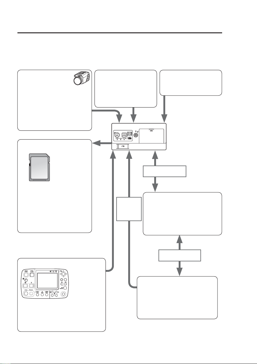
Functions of This Recorder
An AG-CPD20P is a vehicle video recorder using SDHC Memory Cards.
A separately sold video camera, commercially available radar gun, and microphones
can be connected to the recorder. The recorder can be controlled using a separately
sold remote control panel, or software installed on a personal computer.
Camera
Up to six cameras can
be connected, and pictures
captured by five of them can be
recorded as one- or two-window
pictures simultaneously.
with a separately sold color
camera and five commercially
(
available cameras.
→ page 17
)
SDHC Memory Cards
(sold separately)
Up to four SDHC Memory Cards
can be inserted in this recorder for
recording. Video and audio signals
are recorded on SDHC Memory
Cards. In addition, meta-data
such as recording date and time,
recording trigger, etc. can also be
recorded.
→ page 8, 10 and 18-19
Remote control panel
(sold separately)
RETURN
MENU
CONTROLPANEL
ON/
OFF
This panel controls the recorder.
The picture is displayed on the LCD.
→ page 17
• For details on operation, refer to “Section
2: Operation.”
Audio input
Four audio input connectors
enable recording of up to
four-channel microphone or
line signals.
→ page 17
Wired LAN
(commercially available)
Wired LAN/
USB wireless
LAN module
(commercially
available)
Front End Application
This is free application software for
operating the recorder, playing back
pictures, uploading recorded data, etc.
• For details, refer to the Operating
Back End Application
This is free application software
for server. Playback of pictures,
editing, searching for data and user
management, etc. are available.
• For details, refer to the Operating
Instructions for Back End Application.
Rader Gun
(commercially available)
→ page 17
Instructions for Front End
Application.
Wireless LAN
(commercially available)
6
Page 7

Included Accessories
Key .....................................................2
Options
Remote Control Panel
(AG-RCP30P)
Color Camera (AG-CK10P)
Cable Kit (AG-CR13P)
Power cable
Trigger cable
GPS antenna + Antenna mounting
plate
PC Applications (free software)
Front End Application
(AG-JJLFE20P)
Back End Application
(AG-JJLBE20P)
About Manuals of This Recorder
Manuals for this recorder are prepared in two parts: “Section 1: Before Use” (this
manual) and “Section 2: Operation” (PDF manual).
Section 1: Before Use (This Manual)
Section 2: Operation (for operations using the remote control panel, etc.) (PDF)
Definition of terms
Officer: anybody using the Remote Control Panel, Front End Applications,
or Back End Application to control the recorder
Administrator: a user with administrator privileges to collect and manage Memory
Card Recorder data
Figures in this manual
Figures for the main unit and display on the menu screen may differ from the
actual product.
7
Page 8

Before Use
Always take a trial shoot.
Before making important recordings,
always take a trial shoot to confirm
that recording works as expected.
Especially when using “Backlighting
Compensation” or “Night Shooting
with the IR Function”, verify that your
settings produce the desired results.
When using for the first time
or when using in a place with
a different time zone, set the
correct time zone.
The factory default time zone setting
is “Eastern DST”.
When using in a different time zone,
set the time zone for that region
(refer to “TimeZone” in Section 2:
Operation).
Recording officer data on this
unit allows you to find out the
person performed recording
later (refer to “Setting up/Deleting
Officer Data” in Section 2: Operation).
Use together with the Remote
Control Panel and other
specified, separately sold
accessories.
This unit can be controlled by
application software running on
a Remote Control Panel or a PC
(referred to as PC application in
this manual).
•
For details on how to run the PC
application, see the Operating
Instructions of the PC application.
• Connecting a personal computer
(referred to as PC in this manual)
to this unit and starting up Front
End application on the PC freezes
this unit in the live screen and
disables the other operations.
Usable memory cards
The recorder is recommended to
use an SDHC Memory Card (16 GB
or 32 GB) having “SDHC” logo,
made by Panasonic, and conforming
to Class 6 or Class 10 of SD speed
class.
Do not turn the power off while
recording.
Be sure to stop all operations
before turning the power off (refer to
“Stopping Recording” in Section 2:
Operation).
Turning the power off especially
during access (for example,
during recording) may damage the
SDHC Memory Card or corrupt
file management data, setting
information and other data on
the SDHC Memory Card. If file
data cannot be read correctly due
to corrupted file management
information on the SDHC
Memory Card, the card should
be reformatted. For details on
reformatting, refer to “Format” in
Section 2: Operation or contact your
supplier.
• In no event will Panasonic be liable for any damages, including any incidental
or consequential damages, stemming from a failure to record data or from lost
settings or data.
Any of the following actions can result in problems:
• Power supply to the recorder is interrupted or impaired during recording, for
example by starting an engine.
•
If an SDHC Memory Card is ejected while it is being accessed (for example
during recording).
8
Page 9

Before Use
(continued)
About the Internal Clock
Confirming the Time
The internal clock is set at the time
of factory default. Check the time
before using, and reset the clock if
necessary. (Refer to “Date/Time” in
Section 2: Operation.)
Note:
To use GPS, connect the
GPS antenna (included in the
separately sold Cable Kit) to the
[GPS ANT.] connector on the rear
panel.
Consult your supplier and request
connection.
During GPS reception, the
signals received will regularly and
automatically set the recorder
clock to GPS time.
Time Zone Setting
The factory default time zone setting
is “Eastern DST”.
When using in a different time zone,
set the time zone for your region.
(Refer to “TimeZone” in Section 2:
Operation.)
9
Page 10

Notes on Handling
Usage
• Do not remove an SDHC Memory
Card while it is being accessed, as
the SDHC Memory Card may be
damaged or the SDHC Memory
Card slot may become disabled.
• Do not set liquid containers or
small metal objects on the recorder
or SDHC Memory Cards.
• Do not insert foreign objects into
the openings of any devices.
• Do not attempt to modify the
recorder or SDHC Memory Cards.
•
Do not use the recorder in a place
where it or an SDHC Memory Card
might get wet, or water might get
inside them.
• The recorder is intended to work
only with SDHC Memory Cards.
Do not attempt to use non-SDHC
Memory Cards, as that could
damage the recorder.
• When inserting an SDHC Memory
Card, make certain that it is not
upside down or backwards, and
do not attempt to force a bent or
damaged SDHC Memory Card,
as that could damage the card or
SDHC Memory Card slot.
• While the recorder is operating
(and especially recording), do
not disconnect the recorder’s
power cable (included in the
separately sold Cable Kit). Before
disconnecting the power cable,
first stop all operations and turn
the recorder off. Otherwise, the
SDHC Memory Card may be
damaged, or recorder setting files
or management data on the SDHC
Memory Card may be corrupted.
Precautions for use of SDHC
Memory Cards
• If an SDHC Memory Card that has
been used with another device is
to be used, format it with the “SD
Memory Card Formatting Software”
which can be downloaded from the
following Web site:
http://panasonic.jp/support/global/
cs/sd/download/sd_formatter.html
(Refer to “Format” in Section 2:
Operation.)
• Since the number of recording
files on an SDHC Memory Card is
limited, exceeding the maximum
number of recording files will detect
an end of card event even if there is
space left on the card.
Maintenance
• To clean the recorder, turn the
vehicle’s ignition switch to the
LOCK (OFF) position, and keep the
recorder power turned off (see “Off”
on page 20).
• Do not use solvents such as
benzene, thinner or alcohol, as
these can deform the case or
damage the surface finish.
• Use a soft, dry cloth to dust off the
recorder. If severely soiled, wipe it
with a cloth moistened with a weak
solution of mild synthetic detergent
and wrung out, and afterwards
wipe with a dry cloth.
• If using a chemically treated cloth,
follow the instructions provided
with it.
10
Page 11

Control Reference Guide
Front panel (1)
REC button ( )
Starts recording of video and sound
to an SDHC Memory Card.
STOP button ( )
Stops recording.
SDHC Memory Card lamps 1,
2, 3, and 4
Light in green when SDHC Memory
Cards are inserted in the SDHC
Memory Card slots. The lamp for the
card to be used for recording lights
in orange (refer to “Indicator Lamps
and Recorder Status” in Section 2:
Operation).
SDHC Memory Card slots 1, 2,
3, and 4
Insert SDHC Memory Cards here.
Up to four cards can be inserted
simultaneously.
REC lamp
Lights up during recording. If the
combined remaining recording time
for the cards inserted in the SDHC
Memory Card slots 1, 2, 3, and 4 is
less than 30 minutes, the lamp starts
flashing (refer to “Indicator Lamps
and Recorder Status” in Section 2:
Operation).
READY lamp
Lights up when recording is possible
on an SDHC Memory Card inserted
in an SDHC Memory Card slot (refer
to “Indicator Lamps and Recorder
Status” in Section 2: Operation).
BUSY lamp
Lights up or flashes while an SDHC
Memory Card is accessed (recording
or playback; refer to “Indicator
Lamps and Recorder Status” in
Section 2: Operation).
UPLOAD lamp
Stays lit while the recorder is
connected with a Back End
Application installed.
While data recorded on an SDHC
Memory Card are being uploaded
or exported, the lamp flashes (refer
to “Indicator Lamps and Recorder
Status” in Section 2: Operation).
11
Page 12

Control Reference Guide
Front panel (2)
USB connector
A commercially available USB memory
device can be connected for use as
external memory.
Not all USB memory devices may be
recognized.
(continued)
USB connector cover
Close the cover to prevent foreign
objects from getting into the
connector when a USB memory
device is not to be used.
Lock
Locks and unlocks the SDHC
Memory Card slot cover.
SDHC Memory Card slot cover
Protects the SDHC Memory Cards.
Recording is disabled when open.
12
Page 13

Control Reference Guide
Rear panel (1)
(continued)
CAMERA 1 connector
Connect the separately sold Color
Camera using the cable attached to
the Camera.
CAMERA 2 (brown), 3 (red),
4 (green), 5 (orange), 6 (blue)
connectors (Pin jack)
These are composite signal inputs.
Connect commercially available
cameras.
VIDEO OUT 1 (yellow),
2 (yellow) connectors
(Pin jack)
These are composite signal outputs.
VIDEO OUT 1:
Provides output of the video applied
to the [CAMERA 1] or
[CAMERA 3] connector, or the same
signal as the output of the [VIDEO
OUT 2] connector by setting with the
menu.
(Refer to Section 2: Operation
“Setting the output video”.)
VIDEO OUT 2:
Accepts connection of the cable
attached to the separately sold
Remote Control Panel.
AUDIO OUT (white) connector
(Pin jack)
This is a line level signal output.
Accepts connection of the cable
attached to the separately sold
Remote Control Panel.
CONTROL PANEL (CP)
connector
Connect the separately sold Remote
Control Panel using the cable attached
to the Remote Control Panel.
LAN (UPLOAD, PC)
connectors
Connect the recorder to PCs using
commercially available LAN cables.
Note:
For details on how to connect a PC,
contact your supplier.
GPS ANT. connector
Insert the cable from the GPS
antenna (included in the separately
sold Cable Kit). During GPS
reception, the signals received will
regularly and automatically set the
recorder clock to GPS time.
13
Page 14

Control Reference Guide
Rear panel (2)
(continued)
AUDIO IN 1 (black), 2 (red),
3 (black), and 4 (black)
connectors (Pin jack)
These are line or microphone level
signal inputs.
The output signals of audio
components or wireless microphones
can be connected here.
SERIAL connector
For RS-232C. Connect a
commercially available radar gun.
GPIO connector
This combo connector accepts
up to 16 trigger signal (GPI1-16)
inputs and supplies up to four signal
(GPO1-4) outputs. Connect the
trigger cable here (included in the
separately sold Cable Kit).
USB connector
Connect a specified, commercially
available wireless LAN module. (For
a specified, commercially available
wireless LAN module, consult your
supplier.)
DC IN connector
( )
This connector accepts power from
the vehicle battery.
Connect the power cable here
(included in the separately sold
Cable Kit).
Note:
Do not pull out the power cable
(included in the separately sold
Cable Kit) while the recorder is
running. Turning the power off
especially during access (for
example, during recording) may
damage the SDHC Memory Card
or corrupt file management data,
setting information and other data on
the SDHC Memory Card.
Cable Clamp
Use this clamp to affix video, audio,
camera cables and the power cable
(included in the separately sold
Cable Kit).
14
Page 15

Control Reference Guide
(continued)
Mounting bracket
The recorder can be mounted turned by 90° in a center console or trunk. The figure
below is an example of mounting in a center console. (Factory default setting)
For trunk mounting, remove the screw to remove the mounting bracket. Rotate the
mounting bracket 90° and attach the screw again.
Top
Front
Spaces for mounting holes
In these spaces the holes can be
made to mount the recorder on the
center console or trunk.
∗ Consult your supplier and request help with installation.
∗
15
Page 16

Connections
• Be sure to consult your supplier and request installation and connection.
• Connect the red (BATT) and white (SIGNAL) wires of the power cable via a fuse
(7.5 A) having UL Listing.
(The power cable is included in the separately sold Cable Kit.)
• Connect the power cable from the passenger compartment fuse box. Use a
commercially available automotive cable to provide power from the engine
compartment to operate the recorder in the passenger compartment.
• Connect the power cable when all connections are completed. Be sure to read the
instructions in the connector diagram on pages 21 through 23 and the operating
instructions of the devices that will be connected.
• Verify that recording is not in progress prior to disconnecting any cables from the
recorder.
cables.
• An incorrectly connected power cable could cause a fire or damage. Be sure to
connect the power cable correctly.
Be sure to disconnect the power cable first, and then disconnect any other
16
Page 17

Connections
(continued)
PC (commercially available,
for Back End Application)
For using the LPR
mode, use the [VIDEO
OUT 1] connector.
(Refer to “Setting LPR
mode” in Section 2:
Operation.)
Cameras
(commercially
available)
Remote Control Panel
(sold separately)
LAN cable
(commercially
available)
PC (commercially available,
for Front End Application)
LAN cable
(commercially available)
GPS antenna
(included in the
separately sold
Cable Kit)
Audio input 1-4
Camera cable
(provided with
the separately
sold Color
Camera)
Color Camera
(sold separately)
Connect a
commercially
available radar
gun
Trigger cable
(included in the separately
sold Cable Kit)
GPI 1-16
GND×2
GPO 1-4
DGND
Wireless LAN module
Black
(GND: )
Red
(BATT: )
White
(SIGNAL)
(specified,
commercially
available)
: Connect to the negative
terminal of the battery.
: Connect to a terminal that
always supplies power
through a fuse, regardless
of whether the engine is
on or off.
: Connect the signal line
through a fuse to the
ACC line or to the
output terminal of a
timer device.
Power cable
(included in the
separately sold
Cable Kit)
17
Page 18

SDHC Memory Card Insertion and Removal
Do not insert or remove an SDHC Memory Card when another SDHC Memory
Card is being accessed (while the [BUSY] lamp is lit or blinking). Otherwise the
SDHC Memory Card may be damaged or SDHC Memory Card data may be
corrupted.
Inserting an SDHC Memory
Card
(1) Open the SDHC Memory Card
slot cover.
Insert the key in the lock and
turn it clockwise to [ ].
Notes:
• Do not try to turn the key further
than the stop position, and do not
move it unnecessarily, to prevent
damage to the key and lock.
• To prevent damage, do not exert
undue force on the open cover.
(2) Insert an SDHC Memory Card
into the SDHC Memory Card
slot and push it in until it
clicks.
Insert the card with the logo
facing up and with the cutoff corner on the right.
Note:
The [BUSY] lamp blinks for a few
seconds when the SDHC Memory
Card slot cover is opened. Make
sure that the blinking has stopped
before inserting an SDHC Memory
Card.
(Continued on the next page)
Do not push in
this direction.
18
Page 19

SDHC Memory Card Insertion and Removal
(continued)
(3) Close the SDHC Memory Card
slot cover.
Return the SDHC Memory Card
slot cover to its original closed
position and press the section
marked
When you close the SDHC Memory
Card slot cover after inserting an SDHC
Memory Card, the [READY] lamp
indicates the recorder status.
(Refer to “Indicator Lamps and
Recorder Status” in Section 2:
Operation.)
PUSH
.
(4) Remove the key.
Turn the key counterclockwise to
[ ], and remove it.
Note:
The [BUSY] lamp blinks for a few
seconds when the SDHC Memory
Card slot cover is opened. Make
sure that the blinking has stopped
before removing an SDHC Memory
Card.
Note:
If an SDHC Memory Card was
removed while it was being
accessed, the files may be
corrupted. The corrupted files are
automatically repaired.
(For details, refer to “Restoring
Files Automatically” in Section 2:
Operation.)
(3) Close the SDHC Memory Card
slot cover.
Return the SDHC Memory Card
slot cover to its original closed
position and press the section
marked
PUSH
.
Removing an SDHC Memory Card
(1) Open the SDHC Memory Card
slot cover (see previous page).
(2) Push the center of the card
until it clicks so that the
SDHC Memory Card pops out
then pull it out straight.
(4) Remove the key.
Turn the key counterclockwise to
[ ], and remove it.
19
Page 20

Turning the Recorder On and Off
Recorder power is supplied from the vehicle’s battery.
On
Turn the vehicle’s ignition switch
to ON or ACC.
Power to the recorder is turned on.
If the Remote Control Panel is
connected, its power is also turned
on.
Off
Turn the vehicle’s ignition switch
to LOCK (OFF).
Power to the recorder is turned off.
If the Remote Control Panel is
connected, its power is also turned
off.
Notes:
• The recorder cannot be turned off
from the Remote Control Panel.
• The [PowerOff Time] can be
set (refer to “PowerOff Time” in
Section 2: Operation) to allow the
recorder to continue operating
for up to 180 minutes after the
vehicle’s ignition switch is turned to
LOCK (OFF).
20
Page 21

Connector Signals
[CAMERA 1] connector
(male)
1
2 16
[DC IN] connector
(male)
12V/24V
1
15
4
Pin
number
1 N.C.
2 GND (SHIELD)
3 V_OUT
4 GND (V_OUT)
5 BL_L
6 GND (TxD/RxD)
7 AUTO_ZOOM_L
8 TxD
9 REC_L
10 RxD
11 GND (DC_IN)
12 REC_LED_L
13 DC_IN
14 GND (SHIELD)
15 N.C.
16 GND (SHIELD)
Pin
number
1
2
3 SIGNAL
4 N.C.
Signal Cable color
GND (
BATT (
)
)
∗
Signal
Black
Red
White
Black
Red
White
Power cable (included in the separately sold Cable Kit)
∗ Recorder power can be turned on and off by the SIGNAL port. If an OFF signal is
input while the recorder is operating, the recorder turns off after the time specified
on the Remote Control Panel.
21
Page 22

Connector signals
(continued)
[GPIO] connector (female)
13
25 14
Trigger cable
(included in the separately
sold Cable Kit)
GPO 1 Open emitter output
GPO 2 Open emitter output
GPO 3 Open collector output
GPO 4 Power output of 5 V
Pin
number
1
Signal
Cable color
1 GND Black/White
2 N.C. ―
3 GPI 13 Pink
4 GPI 14 Light Green
5 GPI 15 Brown/White
6 GPI 16 Orange/White
GND
7
(DIGITAL)
Green/Black
8 GPO 2 Green/White
9 GND Black
10 GPI 1 Brown
11 GPI 2 Red
12 GPI 3 Orange
13 GPI 4 Yellow
14 GPI 9 Blue/White
15 GPI 10 Violet/White
16 GPI 11 Red/Black
17 GPI 12 Orange/Black
18 GPO 3 Yellow/Black
19 GPO 4 Red/White
20 N.C. ―
21 GPI 5 Green
22 GPI 6 Blue
23 GPI 7 Violet
24 GPI 8 Gray
25 GPO 1 White
[SERIAL] connector
(male)
1
∗
69
Pin
number
1 N.C.
2 RxD
3 TxD
4 DTR
5
1
5 SG
6 DSR
2
∗
RTS
7
2
∗
CTS
8
9 N.C.
∗1 Consult your supplier and request radar gun connection.
∗2 Pins 7 and 8 on this recorder are short-circuited.
22
Signal
Page 23

Connector signals
(continued)
[CONTROL PANEL] connector
(male)
1
210
9
Pin
number
1 N.C.
2 N.C.
3 DC_IN
4 GND (DC_IN)
5 SOUT_P
6 SOUT_N
7 SIN_P
8 SIN_N
9 GND (DIGITAL)
10 GND (FG)
Signal
23
Page 24

Specifications
Power requirements:
12 V DC / 24 V DC
Input current
1.3 A (at 24 V DC)
Current consumption in standby
indicates safety information.
Operating temperature:
0
°C
to 45 °C (32 °F to 113 °F)
Storage temperature:
–20 °C to 60 °C (–4 °F to 140 °F)
Operating humidity:
10 % to 80 % (no condensation)
Weight
1,600 g (3.53 lb)
: 2.7 A (at 12 V DC)
1 mA (12 V DC/24 V DC)
Dimensions (W x H x D)
(excluding protrusions and recorder
mounting brackets)
178 mm x 87 mm x 155 mm
(
:
7 inches x 3-7/16 inches x 6-3/32 inches
Video format:
NTSC (525 lines, 60 fields)
Recording media:
SDHC Memory Card
)
24
Page 25

Specifications
(continued)
Video
Inputs:
CAMERA 1 x 1
1.0 V [P-P], 75 Ω, unbalanced
CAMERA 2-6 (Pin jack) x 5
1.0 V [P-P], 75 Ω, unbalanced
Outputs:
VIDEO OUT 1 - 2 (Pin jack) x 2
1.0 V [P-P], 75 Ω, unbalanced
Audio
Inputs:
AUDIO IN 1 - 4 (Pin jack) x 4
WMIC: –10 dBV, 25 kΩ,
unbalanced
MIC: –50 dBV, 3 kΩ, unbalanced
(plug-in power approx. 4 V)
(selectable)
Output:
AUDIO OUT (Pin jack) x 1
–6 dBV, 600Ω, unbalanced
DC IN connector
SIGNAL port
Input voltage L: 0 V - 1.0V
H: 8 V - 28 V
Input current: 1 mA (max.)
Other I/O connectors
• GPIO connector x 1
D-Subminiature 25-pin
GPIO
Inputs: 16 ports
Input voltage L: 0 V - 1.0 V
H: 4 V - 28 V
Input current: 12 mA (max.)
(Time required to
detect changes: 100 ms)
Outputs: 4 ports
Open-emitter output x 2
Output voltage: approx. 4.5 V
Output current: 15 mA (max.)
Open-collector output x 1
Input voltage: 4 V - 28 V
Input current: 25 mA (max.)
DC output x 1
Output voltage: approx. 5.0 V
Output current: 50 mA (max.)
• CAMERA 1 connector x 1
16-pin, for AG-CK10P
• CONTROL PANEL connector x 1
10-pin, for AG-RCP30P
• LAN connector x 2
RJ-45, connected to a PC
application 1000 BASE-T/100
BASE-TX
• GPS ANT connector x 1
GT5 connector for GPS antenna
(included in the separately sold AGCR13P)
• USB connector x 2
USB A connector for USB memory
device and for USB wireless LAN
client
Compliant with USB Ver.2.0
Bus power current : 500 mA (max.)
• SERIAL connector x 1
D-Subminiature 9-pin
RS-232C
Weight and dimensions are approximate.
Specifications are subject to change
without notice.
25
Page 26

Panasonic Computer Solutions Company
Worldwide Product Warranties
Section 1: Limited Warranty - Hardware
Panasonic Computer Solutions Company (referred to as
"Panasonic") will repair the products listed below with new or
rebuilt parts, free of charge in the U.S.A. or other Panasonic
approved location for the period specified below from the date
of original purchase in the event of a defect in materials or
workmanship. These warranties are extended solely to the
original purchaser. A purchase receipt or other proof of date of
original purchase will be required before warranty performance
is rendered.
• Laptop Computers – 3 Years
• PDRC - LCD and Keyboard Assemblies – 3 Years
• MDWD – Mobile Computer and Wireless Display Assemblies
- 3 Years
• Hand-held Computers (P1/P2) – 1 Year
• Arbitrator Video Camera – 1 Year
• Arbitrator Recorder Unit – 1 Year
• Arbitrator Remote Control Panel – 1 Year
• Arbitrator Wireless Receiver Unit – 1 Year
• Arbitrator P2 Card(s) (All Sizes) – 1 Year
• Arbitrator Wireless Microphone(s) / Transmitter – 90 Days
• Arbitrator System Component Interconnect Cables – 90 Days
Main Battery
The battery supplied with the product is covered under the
warranty for one (1) year from date of purchase, except as
excluded in Section 3. Batteries purchased separately are
covered under the warranty for one (1) year from the date of
purchase. A battery furnished under the warranty is covered for
the remaining period of the one year warranty on the original or
purchased battery.
Options and Accessories
The below listed Panasonic brand or supplied options and
accessories are covered under this limited warranty for the
period specified from the date of purchase or as specifically
stated:
• AC Adapter / Power Cord – 3 Years
• Memory Card (Panasonic Brand) – 3 Years
• Car Mount Docking Station PCB or Complete Vehicle
Docking Station – 3 Years
• Port Replicator / I-O Box – 3 Years
• Antenna Pass-through Cable – 3 Years
• Backlit or Full-sized keyboard - 3 Years or assumes warranty
of the unit in which it is installed
• Integrated Panasonic supplied options and kits including, but
not limited to Wireless Modems, Media Bay Drives (Floppy,
CD, DVD, Combo), GPS, Bluetooth, Smartcard Reader, and
Fingerprint readers – 3 Years or assumes warranty period of
the unit in which it is installed provided the integration was
performed by Panasonic or an Authorized Options Integrator
• Hard Drive (separately purchased) – 1 Year
• External USB Drives (CD / DVD / Floppy / Hard Drive) –
1 Year
• Optional Battery – 1 Year
• Battery Charger – 1 Year
• Standard or Digitizer Stylus Pens – 90 Days (physical
damage excluded)
Section 2 - Limited Warranty - Software
Panasonic Computer Solutions Company (referred to as
"Panasonic") warrants to you only that the disk(s) or other
media on which the Programs are furnished will be free from
defects in material and workmanship under normal use for a
period of sixty (60) days from the date of delivery thereof to
you, as evidenced by your purchase receipt.
26
This is the only warranty Panasonic makes to you. Panasonic
does not warrant that the functions contained in the Programs
will meet your requirements or that the operation of the
Programs will be uninterrupted or error free. Panasonic shall
have no obligation for any defects in the disk(s) or other
media on which the Programs are furnished resulting from
your storage thereof, or for defects that have been caused by
operation of the disk(s) or other media.
Panasonic’s entire liability and your exclusive remedy under
this warranty shall be limited to the replacement, in the
United States or other Panasonic designated location, of any
defective disk or other media which is returned to Panasonic's
Authorized Service Center, together with a copy of the
purchase receipt, within the aforesaid warranty period. The
customer is responsible for ensuring that all data is backed up
and made secure during normal use and before sending a unit
for service.
Section 3 - Limited Warranty Exclusions
Specifically excluded from the warranty are:
• All consumable items; such as screen protection films, logo
badges, labels, cleaning cloths, carry cases, manuals, cables,
straps, belts, holsters, tethers, and harnesses and any other
options and accessories not listed above or covered under a
separate warranty
• Failures related to the product operating system, hard
drive image, software setup, software program, virus, other
program(s) or file(s) on the hard drive or in any computer
memory location
• Failures due to BIOS settings or changes, as well as any
cosmetic or physical damage to the unit
• Any unit or device with a missing or altered model number or
serial number label
• Damage which occurs in shipment
• Failures which are caused by products not supplied by
Panasonic
• Failures which result from alteration, accident, misuse,
introduction of liquid or other foreign matter into the unit,
abuse, neglect, installation, maladjustment of consumer
controls, improper maintenance or modification, use not in
accordance with product use instructions
• Failures due to service by anyone other than a Panasonic
Authorized Service Provider
• Failures caused by improper integration by any company
other than Panasonic Configuration and Integration Centers
• Damage, failure, or loss due to the unit being stolen, lost,
misplaced, or used by anyone other than the original purchaser
• Damage that is attributable to acts of God
This warranty only covers failures due to defects in materials
or workmanship which occur during normal use.
Other Limits and Exclusions: There are no other express
warranties except as listed above.
PANASONIC SHALL NOT BE LIABLE FOR LOSS OF DATA
OR OTHER INCIDENTAL OR CONSEQUENTIAL DAMAGES
RESULTING FROM THE USE OF THIS PRODUCT, OR
ARISING OUT OF ANY BREACH OF THIS WARRANTY.
ALL EXPRESS AND IMPLIED WARRANTIES, INCLUDING
THE WARRANTIES OF MERCHANTABILITY AND FITNESS
FOR A PARTICULAR PURPOSE ARE LIMITED TO THE
APPLICABLE WARRANTY PERIOD SET FORTH ABOVE.
Some states do not allow the exclusion or limitation of
incidental or consequential damages, or limitations on how
long an implied warranty lasts, so the above limitations or
exclusions may not apply to you.
This limited warranty gives you specific legal rights, and you
may also have other rights which vary from state to state.
For technical support or to arrange for service on your
Panasonic computer product, call our toll-free 24 hour hotline
at 1-800-LAPTOP5.
Page 27

MEMO
27
Page 28

Panasonic Computer Solutions CompanyPanasonic Computer Solutions Company
50 Meadowlands Parkway, Panazip 2F-5,
Secaucus, NJ 07094
© 2009
P
 Loading...