

Page 1
Operating Instructions
Memory Card Video Recorder
Model No.
AG- P
Car Use only
Before operating this product, please read the instructions carefully and save
this manual for future use.
S0806K1116-M
D
ENGLISH
VQT1A18-1
Page 2
Read this first!
WARNING:
• TO REDUCE THE RISK OF FIRE OR SHOCK HAZARD, DO NOT
EXPOSE THIS EQUIPMENT TO RAIN OR MOISTURE.
• TO REDUCE THE RISK OF FIRE OR SHOCK HAZARD, KEEP THIS
EQUIPMENT AWAY FROM ALL LIQUIDS. USE AND STORE ONLY
IN LOCATIONS WHICH ARE NOT EXPOSED TO THE RISK OF
DRIPPING OR SPLASHING LIQUIDS, AND DO NOT PLACE ANY
LIQUID CONTAINERS ON TOP OF THE EQUIPMENT.
CAUTION:
TO REDUCE THE RISK OF FIRE OR SHOCK HAZARD AND
ANNOYING INTERFERENCE, USE THE RECOMMENDED
ACCESSORIES ONLY.
indicates safety information.
2
Page 3
Read this first!
(continued)
CAUTION:
In order to maintain adequate ventilation, do not install or place this
unit in a book case, built-in cabinet or any other confined space.
To prevent risk of electric shock or fire hazard due to overheating,
ensure that curtains and any other materials do not obstruct the
ventilation.
FCC Note:
This equipment has been tested and found to comply with the limits
for a class A digital device, pursuant to Part 15 of the FCC Rules.
These limits are designed to provide reasonable protection against
harmful interference when the equipment is operated in a commercial
environment. This equipment generates, uses, and can radiate radio
frequency energy, and if not installed and used in accordance with
the instruction manual, may cause harmful interference to radio
communications. Operation of this equipment in a residential area
is likely to cause harmful interference in which case the user will be
required to correct the interference at his own expense.
Warning: To assure continued FCC emission limit compliance, the user
must only use shielded interface cables when connecting to external
units. Also, any unauthorized changes or modifications to this equipment
could void the user’s authority to operate it.
• This recorder is designed for use and installation in a vehicle.
For example, it may be mounted on the center console or in the trunk.
• The installation of this equipment must only be performed by a
professional installer.
CAUTION:
To reduce the risk of fire, the red (BATT) and white (SIGNAL) wires
of the power cable must be connected via fuses (5 A – 15 A) having
UL Listing.
indicates safety information.
3
Page 4

IMPORTANT SAFETY INSTRUCTIONS
(1) Read these instructions.
(2) Keep these instructions.
(3) Heed all warnings.
(4) Follow all instructions.
(5) Do not use this equipment near water.
(6) Clean only with a dry cloth.
(7) Do not block any ventilation openings. Install in accordance with the
manufacturer’s instructions.
(8) Do not install near any heat sources such as radiators, heat registers, stoves,
or any other equipment (including amplifiers) that produce heat.
(9) Only use attachments/accessories specified by the manufacturer, and as
outlined in this manual.
(10) Refer all servicing requests to qualified service personnel. Servicing is
required when the equipment has been damaged in any way, such as
damage to the power supply cord or plug, liquid being spilled on or objects
have fallen into the equipment, the equipment has been exposed to rain or
moisture and does not operate normally, or has been dropped.
4
Page 5

Contents
Before use
Read this first! …………………… 2
IMPORTANT SAFETY INSTRUCTIONS
…4
Features …………………………… 6
Included Accessories …………… 7
Options ……………………………… 7
How to Operate
P2 card Insertion and Removal … 16
Turning the Recorder On and Off
Starting and Stopping Recording
…18
…19
Troubleshooting and Reference
Connector Signals ………………… 41
Vehicle Speed Pulse Setting
Table (at 40 mph) …………………… 44
Vehicle Speed Pulse Setting
Table (at 60 kph) …………………… 46
Indicator Lamps and Recorder
………………………………… 48
Status
Troubleshooting …………………… 49
Information on software for this product
•
Included with this product is software licensed under the GNU General Public License
(GPL) and GNU Lesser General Public License (LGPL), and users are hereby informed
that they have the right to obtain, change and redistribute the source codes of this software.
Details on GPL and LGPL can be found in the GPL and LGPL sections of this manual.
To obtain the source codes, go to the following home page.
http://panasonic.biz/sav/
The manufacturer asks users to refrain from directing inquiries concerning the source
codes they have obtained and other details to its representatives.
• Included with this product is software licensed under the OpenSSL License. Details on
the OpenSSL License can be found in the OpenSSL License section of this manual.
• Included with this product is software licensed under the Blowfish License. Details on
the Blowfish License can be found in the Blowfish License section of this manual.
• Included with this product is software licensed under the DES License. Details on the
DES License can be found in the DES License section of this manual.
•
Included with this product is software licensed under the XFree86 License.
Details on the XFree86 License can be found in the XFree86 License section of this manual.
• This product is licensed under the MPEG-4 Visual patent portfolio license for the
personal and noncommercial use of a consumer for (i) encoding video in compliance
with the MPEG-4 Visual Standard (“MPEG-4 Video”) and/or (ii) decoding MPEG-4 Video
that was encoded by a consumer engaged in a personal and non-commercial activity
and/or was obtained from a video provider licensed by MPEG LA to provide MPEG-4
Video. No license is granted or shall be implied for any other use. Additional information
including that relating to promotional, internal and commercial uses and licensing may
be obtained from MPEG LA, LLC.
See http://www.mpegla.com/
Before Use ………………………… 8
Notes on Handling ………………… 9
Control Reference Guide ………… 10
Connections
………………………… 14
Setup ………………………………… 31
Text Files Used with the
Recorder …………………………… 37
Software License Agreement …… 52
GPL ………………………………… 52
LGPL ……………………………… 55
OpenSSL License ……………… 59
Blowfish License ………………… 60
DES License ……………………… 60
XFree86 License ………………… 61
Specifications ……………………… 68
LIMITED WARRANTY
……………… 70
5
Page 6

Features
Record video on memory cards
Video and audio files can be
recorded on memory cards with the
“P2” logo (such as the separately
sold AJ-P2C008HG afterwards
called P2 cards), in MPEG4 and
G.726 formats.
Record a variety of information
In addition to video and audio files,
meta information including recording
date and time and recording triggers
can be recorded.
Long-term recording
A maximum of 64 hours of recording
is possible (using two 8 GB P2 cards
and recording at a bit rate of 512
kbps).
6
Page 7

Included Accessories
Key ....................................................1 Mounting bracket
(attached to the recorder)
Options
Remote Control Panel
(AG-RCP30P)
Color Camera (AG-CK10P)
GPS module (AG-GPS15P)
Cable Kit (AG-CR12P)
Network Cable Kit (AG-CR11P)
P2 card (8 GB: AJ-P2C008HG)
(4 GB: AJ-P2C004HG)
..................2
7
Page 8

Before Use
Always take a trial shoot.
Before making important recordings,
always take a trial shoot to confirm
that recording works as expected.
Especially when using “Backlighting
Compensation” or “Night Shooting
with the IR Function”, verify that
your settings produce the desired
results.
Use together with the Remote
Control Panel and other
specified, separately sold
accessories.
When using for the first time
or when using in a place with
a different time zone, set the
correct time zone.
The factory default time zone setting
is “Eastern Standard Daylight Saving
Time”.
When using in a different time zone,
set the time zone for that region.
Usable memory cards
The recorder is designed to use any
P2 card having the “P2” logo.
Do not turn the power off while
recording
Be sure to stop all operations before
turning the power off (page 21).
Turning the power off especially
during access (for example, during
recording) may damage the P2
card or corrupt file management
data, setting information and
other data on the P2 card. If file
data cannot be read correctly due
to corrupted file management
information on the P2 card, the
card should be reformatted. For
details on reformatting, refer either
to the Operating Instructions of the
Remote Control Panel or contact
your supplier.
• In no event will Panasonic be liable for any damages, including any incidental
or consequential damages, stemming from a failure to record data or from lost
settings or data.
Any of the following actions can result in problems:
• Power supply to the recorder is interrupted or impaired during recording, for
example by starting an engine.
• If a P2 card is ejected while it is being accessed.
8
Page 9

Notes on Handling
Usage
• Do not remove a P2 card while
it is being accessed, as the P2
card may be damaged or the P2
card slot may become disabled.
When the recorder senses a
disabled slot, it may reboot itself
automatically.
• Do not set liquid containers or
small metal objects on the recorder
or P2 cards.
• Do not insert foreign objects into
the openings of any devices.
• Do not attempt to modify the
recorder or P2 cards.
•
Do not use the recorder in a place
where it or a P2 card might get wet,
or water might get inside them.
• The recorder is intended to work
only with P2 cards. Do not attempt
to use non-P2 cards, as that could
damage the recorder.
• When inserting a P2 card, make
certain that it is not upside down
or backwards, and do not attempt
to force a bent or damaged P2
card, as that could damage the
card or P2 card slot.
• While the recorder is operating
(and especially recording), do
not disconnect the recorder’s
power cable (included in the
separately sold Cable Kit). Before
disconnecting the power cable,
first stop all operations and turn
the recorder off. Otherwise, the P2
card may be damaged, or recorder
setting files or management data
on the P2 card may be corrupted.
Maintenance
• To clean the recorder, turn the
vehicle’s ignition switch to the
LOCK (OFF) position, and keep
the recorder power turned off
(page 18).
• Do not use solvents such as
benzene, thinner or alcohol, as
these can deform the case or
damage the surface finish.
• Use a soft, dry cloth to dust off the
recorder. If severely soiled, wipe it
with a cloth moistened with a weak
solution of mild synthetic detergent
and wrung out, and afterwards
wipe with a dry cloth.
• If using a chemically treated cloth,
follow the instructions provided
with it.
9
Page 10
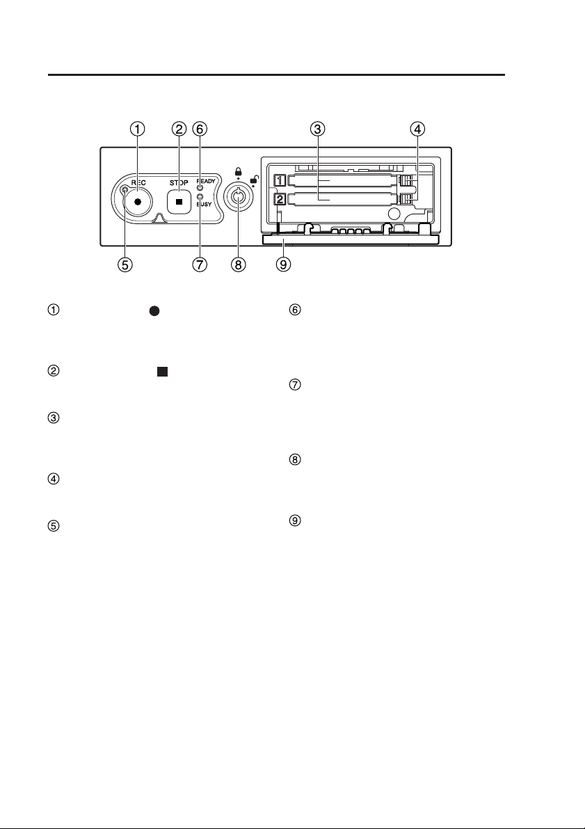
Control Reference Guide
Front panel
REC button ( )
Starts recording of video and sound
to a P2 card.
STOP button ( )
Stops recording.
P2 card slots 1, 2
Insert P2 cards here. Up to two cards
can be inserted simultaneously.
Eject button
Serves to eject a P2 card.
REC lamp
Lights up during recording. If the
combined remaining recording
time for the cards inserted in the
P2 card slots 1 and 2 is less than
30 minutes, the lamp starts to flash
(see page 48).
READY lamp
Lights up when recording is possible
on a P2 card inserted in a P2 card
slot (see page 48).
BUSY lamp
Lights up or flashes while a P2 card
is accessed (recording or playback;
see page 48).
Lock
Locks and unlocks the P2 card slot
cover.
P2 card slot cover
Protects the P2 cards.
Recording is disabled when open.
10
Page 11
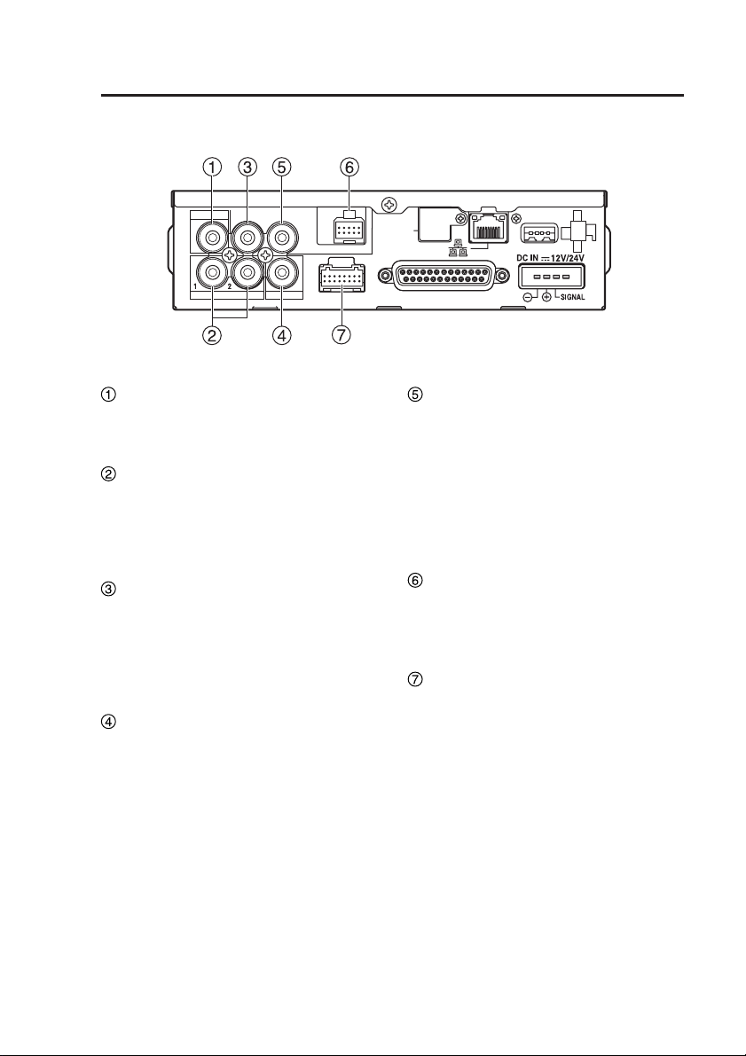
Control Reference Guide
Rear panel (1)
VIDEO OUT
AUDIO OUT
IN CAR MIC
CONTROL PANEL
GPS-ANT.
(OPTION)
(continued)
USB
AUDIO IN
CAMERA 2
CAMERA 1
IN CAR MIC connector
(Pin jack)
This is a mic level signal input.
AUDIO IN 1, 2 connectors
(Pin jack)
These are line level signal inputs.
The output signals of audio
components can be connected here.
AUDIO OUT connector
(Pin jack)
This is a line level signal output.
Accepts connection of the cable
attached to the separately sold
Remote Control Panel.
CAMERA2 connector
(Pin jack)
This is a composite signal input.
Connect a commercially available
camera.
GPIO/SERIAL
VIDEO OUT connector
(Pin jack)
This is a composite signal output.
Provides output of the video applied
to the [CAMERA1] or [CAMERA2]
connector.
Accepts connection of the cable
attached to the separately sold
Remote Control Panel.
CONTROL PANEL connector
Connect the separately sold Remote
Control Panel using the cable attached
to the Remote Control Panel.
CAMERA1 connector
Connect the separately sold Color
Camera using the cable attached to
the Camera.
11
Page 12
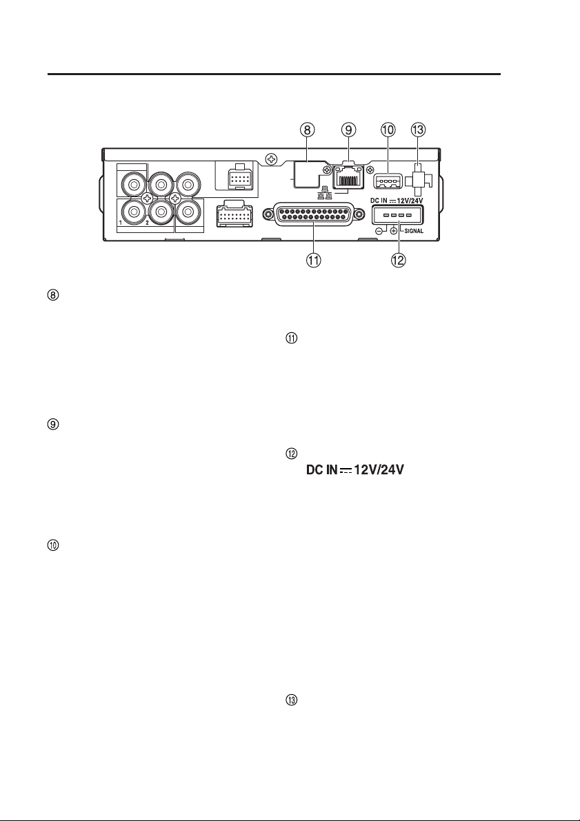
Control Reference Guide
Rear panel (2)
VIDEO OUT
AUDIO OUT
IN CAR MIC
CONTROL PANEL
GPS-ANT.
(OPTION)
(continued)
USB
AUDIO IN
GPS-ANT. (OPTION) connector
CAMERA 2
CAMERA 1
When the separately sold GPS
module is installed, insert the cable
from the GPS antenna (attached
to the GPS module). During GPS
reception, the signals received will
regularly and automatically set the
recorder clock to GPS time.
LAN connector
Connect a LAN cable (included in the
separately sold Network Cable Kit).
Note:
For details on how to connect a PC
or run PC applications, contact your
supplier.
USB connector
A commercially available USB memory
device can be connected for use as
external memory.
Not all USB memory devices may be
recognized.
Notes:
•
To protect the [USB] port, connect
the USB extension cable (included
in the separately sold Cable Kit) to
the recorder before connecting a
commercially available USB memory
device
.
• A maximum of two USB memory
devices can be connected when
using a commercially available
USB hub.
12
GPIO/SERIAL
• Consult your supplier for help with
connection.
GPIO/SERIAL connector
This connector accepts up to eight
trigger signal inputs and provides
one Rec Tally output and a serial
port. Connect the trigger cable here
(included in the separately sold
Cable Kit).
DC IN connector
( )
This connector accepts power from
the vehicle battery.
Connect the power cable here
(included in the separately sold
Cable Kit).
Note:
Do not pull out the power cable
while the recorder is running.
Turning the power off especially
during access (for example, during
recording) may damage the P2 card
or corrupt file management data,
setting information and other data
on the P2 card.
Cable Clamp
Use this clamp to affix video, audio,
camera cables and the power and
USB extension cables included in
the separately sold Cable Kit.
Page 13
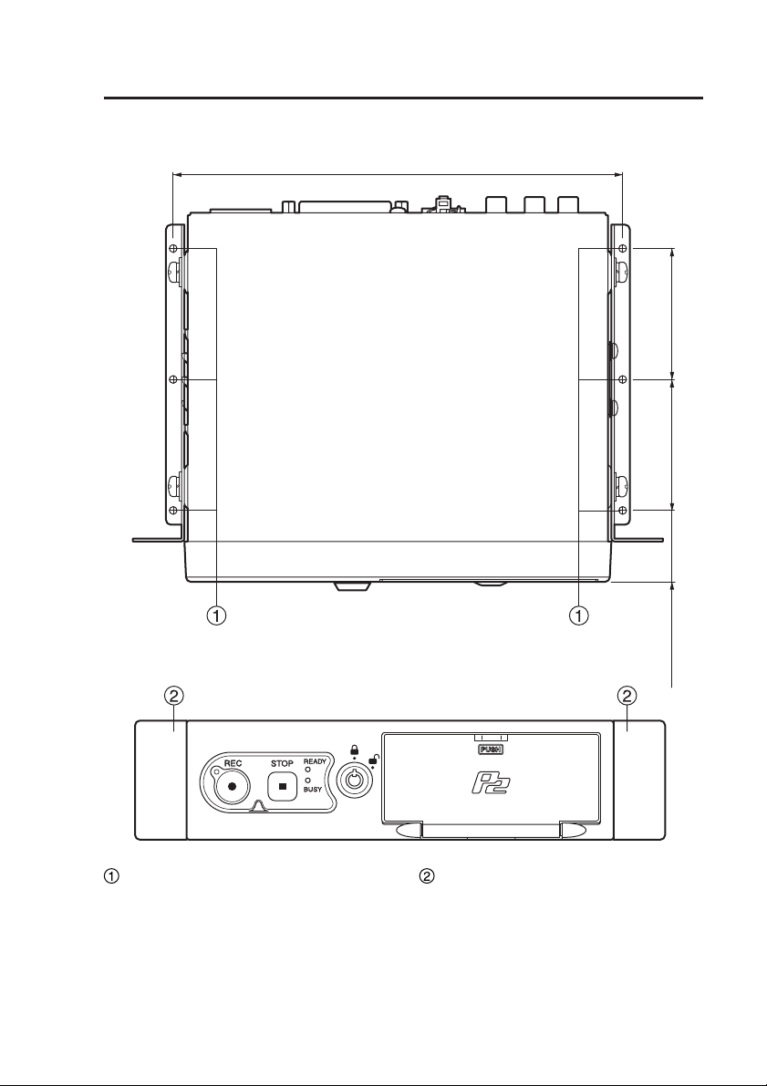
Control Reference Guide
Mounting bracket
(continued)
Top
Front
187.4
(7-3/8 inches)
<Unit : mm>
(2-5/32 inches)
55
(2-5/32 inches)
55
(1-5/32 inches)
30
Trunk mounting holes (ø3.2)
These holes are used to mount the
recorder in the trunk. Consult your
supplier for help with installation.
Spaces for center console
mounting holes
In these spaces the holes can be
made to mount the recorder on the
center console.
Consult your supplier for help with
installation.
13
Page 14

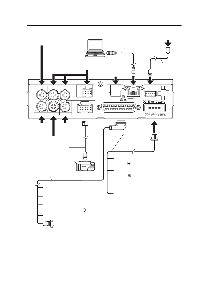
Connections
• For details on installation and connections, be sure to contact your supplier.
• Connect the red (BATT) and white (SIGNAL) wires of the power cable via a fuse
(5 A – 15 A).
(The power cable is included in the separately sold Cable Kit.)
• Connect the power cable from the passenger compartment fuse box.
Use a separately sold automotive cable to provide power from the engine
compartment to operate the recorder in the passenger compartment.
• Connect the power cable when all connections are completed. Be sure to
read the instructions in the connector diagram on page 41 and the operating
instructions of the devices that will be connected.
• Verify that recording is not in progress prior to disconnecting any cables from the
recorder.
Be sure to disconnect the power cable first, and then disconnect any other cables.
• An incorrectly connected power cable could cause a fire or damage. Be sure to
connect the power cable correctly.
14
Page 15
Connections
(continued)
Audio input
(mic level)
Remote Control Panel
(separately sold)
VIDEO OUT
AUDIO OUT
IN CAR MIC
AUDIO IN
Audio input 1
(line level)
CAMERA 2
Camera
(commonly
available)
Audio input 2
(line level)
Camera cable
(provided with the
separately sold
Color Camera)
Trigger cable
(included in the separately
sold Cable Kit)
Others: Input signal lines
White: Rec Tally output line
Black: Connect to the negative
terminal (GND: ) of the battery
Gray:
This is the input line for a signal or
vehicle speed pulse
PC
(commonly
available)
CONTROL PANEL
CAMERA 1
Color Camera
(separately sold)
*
LAN cable (included
in the separately sold
Network Cable Kit)
GPS antenna
(provided with the
separately sold
GPS module)
GPS-ANT.
(OPTION)
GPIO/SERIAL
Black
(GND: )
Red
(BATT: )
White (SIGNAL):
USB memory device
(commonly available)
USB Extension
Cable (included
in the separately
sold Cable Kit)
USB
Power cable
(included in the
separately sold
Cable Kit)
: Connect to the negative
terminal of the battery
: Connect to a terminal that
always supplies power
through a fuse, regardless
of whether the engine is
on or off
Connect the signal line
through a fuse to the
ACC line or to the
output terminal of a
timer device.
RS-232C:
Connect to a commonly
available radar gun
∗ There are two types of vehicle speed pulse signals: digital waveforms (square
waves) and analog waveforms (AC waveforms). The recorder accepts only
digital waveforms. Ask your supplier about the connection procedure.
15
Page 16
P2 card Insertion and Removal
Do not insert or remove a P2 card when another P2 card is being accessed
(while the [BUSY] lamp is lit or blinking). Otherwise the P2 card may be
damaged or P2 card data may be corrupted.
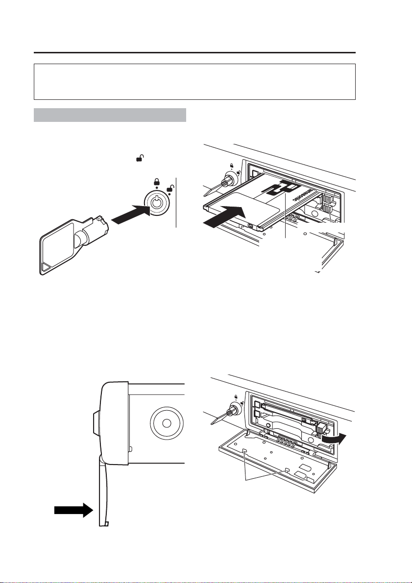
Inserting a P2 card
(1) Open the P2 card slot cover.
Insert the key in the lock and
turn it clockwise to [ ].
Notes:
• Do not try to turn the key further
than the stop position, and do not
move it unnecessarily, to prevent
damage to the key and lock.
• To prevent damage, do not exert
undue force on the open cover.
(2) Insert a P2 card into the P2
card slot and push it in until
the Eject button pops out.
Eject button
Insert the card
with the P2 logo
facing up.
Note:
The [BUSY] lamp blinks for a few
seconds when the P2 card slot
cover is opened. Make sure that
the blinking has stopped before
inserting a P2 card.
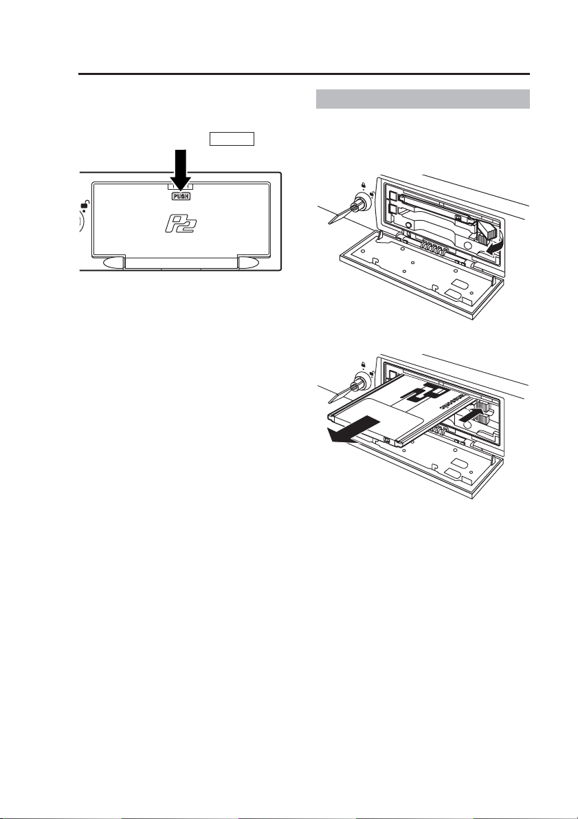
(3) Fold the protruding Eject
button to the right.
Do not push in
this direction.
16
Do not touch to avoid
the risk of injury.
Note:
After confirming that the Eject button
is folded over to the right, close the
P2 card slot cover. Otherwise the
Eject button will be damaged.
Page 17
P2 card Insertion and Removal
(continued)
(4) Close the P2 card slot cover.
Return the P2 card slot cover to its
original closed position and press
the section marked
When you close the P2 card slot cover
after inserting a P2 card, the [READY]
lamp indicates the recorder status (see
page 48).
PUSH
.
(5) Remove the key.
Removing a P2 card
(1) Open the P2 card slot cover
(see previous page).
(2) Raise the Eject button.
(3) Push the Eject button so that
the P2 card pops out.
Note:
The [BUSY] lamp blinks for a few
seconds when the P2 card slot
cover is opened. Make sure that
the blinking has stopped before
removing a P2 card.
Notes:
•
If a P2 card was removed while it
was being accessed, the files may
be corrupted. Refer to the Operating
Instructions of the Remote Control
Panel to restore corrupted files.
• If a P2 card was removed while it
was being accessed, the P2 card
slot may be disabled. When the
recorder senses a disabled slot, it
may reboot itself automatically.
(4) Close the P2 card slot cover
(see top left of this page).
(5) Remove the key.
17
Page 18
Turning the Recorder On and Off
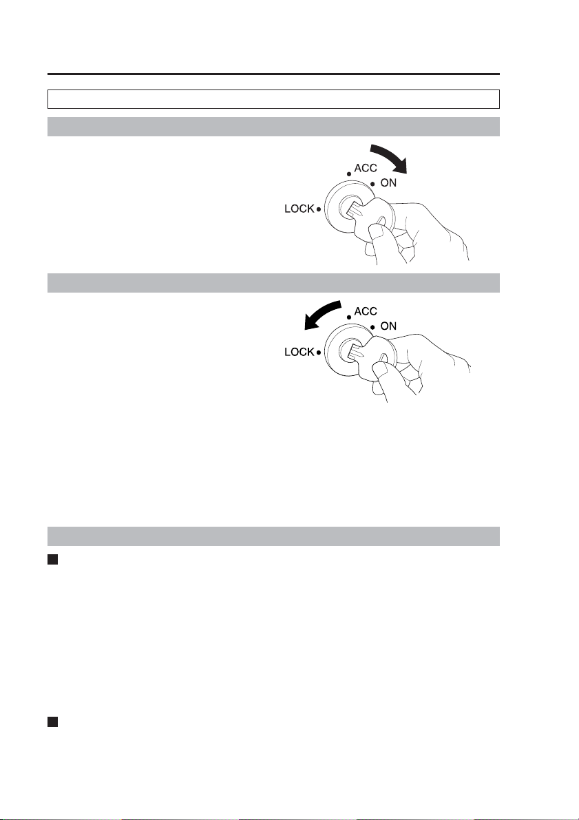
Recorder power is supplied from the vehicle’s battery.
On
Turn the vehicle’s ignition switch
to ON or ACC.
Power to the recorder is turned on.
Off
Turn the vehicle’s ignition switch
to LOCK (OFF).
Power to the recorder is turned off.
Notes:
• The recorder cannot be turned off
from the Remote Control Panel
(separately sold).
• The “PowerOff Time” can be set
(page 31) to allow the recorder to
continue operating for up to 180
minutes after the vehicle’s ignition
switch is turned to LOCK (OFF).
About the Internal Clock
Confirming the Time
The internal clock is set at the time of factory default. Check the time before
using, and reset the clock if necessary.
Note:
To use GPS, install the separately sold GPS module and connect the GPS
antenna (provided with the GPS module) to the [GPS-ANT.] connector on the
rear panel.
Contact your supplier for help with installation or connection.
During GPS reception, the signals received will regularly and automatically set
the recorder clock to GPS time.
Time Zone Setting
The factory default time zone setting is ”Eastern Standard Daylight Saving Time”.
When using in a different time zone, set the time zone for your region.
18
Page 19

Starting and Stopping Recording
Recording
Recording Start Methods
• Press the [REC] button (the REC
buttons on the recorder, Color
Camera and Remote Control Panel
all operate the same way)
• Apply a Recording Trigger
• When power-on recording is
enabled, recording starts when the
recorder is turned on
• Programmed Recording (page 26)
The prerecord function (page 22)
records video for a pre-specified
period prior to a recording-start trigger
event (or pressing the [REC] button).
The amount of the prerecord time is
set from the Remote Control Panel.
You can use this function to prerecord
video without audio. An audio prerecord time, as well as an audio postrecord time, can be set independently,
although it cannot be longer than the
specified video prerecord/postrecord
time.
About Recording Triggers
The following types of recording
triggers are available.
• GPIO Signals
The rising or falling edge, or the
high or low level, of a GPIO signal
can be specified as a recording
trigger.
When using edge trigger, recording
starts when the signal transitions
through the specified edge (for
example, when a rising edge trigger
is specified, recording starts when
the signal transitions from low to
high level).
When using a signal level as a
trigger, recording starts and ends
when the signal reaches and then
departs from the specified level,
respectively.
• Vehicle Speed Signal
Speed data detected by the recorder
serves as a recording trigger when
the specified speed is exceeded.
This signal is handled as an edge
signal to start recording, and is not
used to stop recording.
Select from the following detection
methods according to the intended
application or installation conditions.
Detection of own vehicle speed:
Uses the vehicle speed
Target vehicle speed:
Uses a radar gun
pulse (page 44) or GPS
Note:
To use the vehicle speed pulse,
GPS or radar gun as the recording
trigger, check with your supplier to
ensure that connections have been
made correctly, then specify the
source device (refer to the Operating
Instructions of the Remote Control
Panel).
Notes:
• If both the vehicle speed pulse
and GPS are enabled, the vehicle
speed pulse has priority as the
recording trigger.
After the recording trigger is
detected by vehicle speed pulse or
GPS, if the vehicle is stopped or a
speed of 5 mph or 5 kph below the
set speed is detected, the recording
trigger can be used again.
• Recording is allowed only when
the [READY] lamp on the recorder
is lit. If pressing the [REC] button
or applying a recording trigger fails
to start recording, the [REC] lamps
on the recorder, Color Camera
and Remote Control Panel blink at
a high rate.
19
Page 20

Starting and Stopping Recording
• Video input at the [CAMERA1] or
[CAMERA2] connector (page 31)
is recorded.
• Audio input at the [AUDIO IN 1,2]
or [IN CAR MIC] connectors (page
31) is recorded.
• Recording stops if the P2 card slot
cover is opened.
• Recording cannot start unless the
P2 card slot cover is closed.
• Recording will not start while the
user is configuring administrator
settings, even if the level signal
satisfies the recording start
conditions. In this case, recording
will still not start when the user
quits the administrator settings.
To start recording, the recording
start conditions must be satisfied
again after configuration of the
administrator settings is finished.
• When multiple recording triggers
are enabled, recording starts
when the first recording start
criteria is met, and if a prerecord
time has been set, the specified
period before the start event is
also recorded.
(continued)
20
Page 21
Starting and Stopping Recording
(continued)
Stopping Recording
Setting criteria determine when recording stops. Settings that affect when
recording stops include the stop timer setting for Rec Continue Time and the
presence of the recording trigger level signal. The [STOP] buttons on the recorder
and Remote Control Panel both operate the same way.
Recording Stop Criteria
Level Signal
No No [STOP] button is pressed
Yes No [STOP] button is pressed or the level signal changes
The postrecording function continues to record video after the recording stop
trigger event. The amount of time to continue recording after the stop-recording
event can be set from the Remote Control Panel.
Notes:
•
• If recording time exceeds 17 hours, or if the size of one file would exceed 4
• Once recording starts, it may not be possible to stop it during the first five
• Pressing the [STOP] button when recording is already stopped also causes
• When recording is stopped by the stop timer at the end of the Rec Continue
• After recording is started by a level trigger signal, it continues for at least one
• If the [REC] button was pressed multiple times and the recording trigger set
• Intermittent recording does not stop due to the Rec Continue Time.
Stop Timer Setting
Yes [STOP] button is pressed or the time set for the stop
Yes [STOP] button is pressed, the level signal changes to
Continuous video and audio from starting to stopping recording, and including
prerecording and postrecording periods, are recorded as one file on the P2 card.
GB, the data is automatically split into multiple files during recording.
seconds (approx.). Pressing the [STOP] button during this period causes the
[REC] lamp to blink for about one second as recording continues.
the [REC] lamp to blink for about one second.
Time, the postrecording function is disabled.
minute regardless of changes to the signal level. During this period, you can
press the [STOP] button to interrupt the recording.
as the edge signal had multiple active edges, Rec Continue Time is applied to
the last button press and active edge.
Criteria to Stop Recording (whichever happened earlier)
timer of the edge trigger recording is reached
to an invalid level
an invalid level, or the signal whose level is specified
is invalid and the stop timer setting for the edge
trigger recording is reached
21
Page 22
Starting and Stopping Recording
(continued)
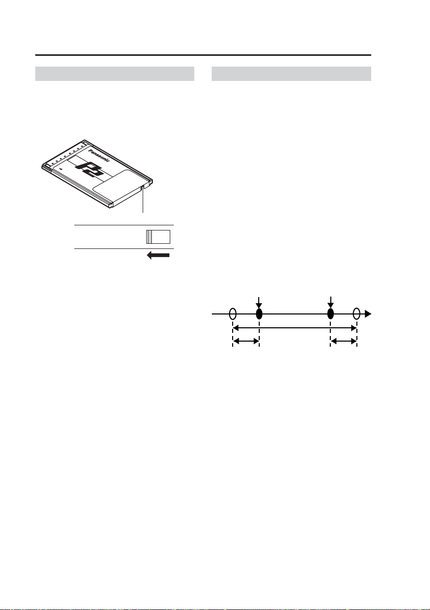
Write-protect switch
The P2 card is equipped with a writeprotect switch. Sliding this switch to the
PROTECT position prevents writing
data, formatting P2 cards and deleting
files.
write-protect switch
PROTECT
Notes:
•
Any attempt to change the position
of the write-protect switch during
power-on will have no effect. To
produce the effect, turn the power off
and then turn it on again or remove
the card and then insert it again.
• If the write-protect switch is set
to the PROTECT position on any
of the cards in the two card slots,
recording will not start.
Prerecording and postrecording
Prerecording is the capability of
including material from an interval
before the specified start point in a
recording. Similarly, postrecording is
the capability of including material from
an interval after the specified stop point
in a recording.
Prerecording and postrecording times
can be set for each recording time.
Audio prerecording and postrecording
times can be set separately from video,
so prerecording and postrecording
audio may be partly omitted. Because
video prerecording and postrecording
time settings have priority, audio
prerecording and postrecording times
cannot be set longer than video
prerecording and postrecording times.
[REC] button pressed
(Recording starts)
Actual recording time
Prerecord time Postrecord time
[STOP] button pressed
(Recording stops)
Time
22
Page 23

Starting and Stopping Recording
(continued)
In the cases shown below, the actual
prerecord and postrecord time may be
shorter than the respective setting.
If recording is started immediately
after system startup
Prerecord time will be shorter.
Startup
completed
[REC] button pressed
(Recording starts)
Actual recording time
Prerecord time Postrecord time
[STOP] button pressed
(Recording stops)
Time
If recording is started during
postrecord interval
Postrecording will be terminated and
next recording starts. There is no
prerecording interval for the second
recording.
[STOP]
button
pressed
[REC] button pressed
(Postrecording halted and
next recording starts)
Postrecord time
Time
Actual recording time
[STOP] button
pressed
(Recording stops)
Postrecord time
Notes:
•
If you press the [REC] button and
[STOP] button alternately in rapid
succession, the system may not
separate the two recording sessions,
resulting in a single video file.
•
If the remaining capacity of the P2
card is low, the prerecord time or postrecord time may become shorter.
•
Postrecording is interrupted by
playback, trial shoot (RecCheck),
file restoration or administrator
setup.
Selecting the video source to record
You can select and record video input
at the [CAMERA1] or [CAMERA2]
connector on the rear panel of the
recorder. Also, if “CAM Select in
Trigger” is enabled, the video input
source can be automatically switched
when recording is started by a trigger
event. If prerecording is enabled and
the video source is switched by a
recording trigger, the prerecord video is
taken from the source selected before
switching, and the video is taken from
the source selected after switching. You
can select whether the video source is
switched by the recording trigger or
not, as well as selecting which video is
recorded upon switching.
Recording start trigger activation
Time
Recording of signal from
[CAMERA2] connector
Prerecording Recording after
Notes:
• When switching video input, the
video or audio may be briefly
disrupted.
• For best results, minimize the
amount of video source switching
while recording.
Recording of signal from
[CAMERA1] connector
trigger activation
23
Page 24

Starting and Stopping Recording
(continued)
Audio sources when recording
The Memory Card Video Recorder
can record up to two audio channels
(AUDIO1 and AUDIO2). Out of the
three audio input connectors on the
rear panel ([AUDIO IN 1, 2], and [IN
CAR MIC]), the signal of the source
connected to the [AUDIO IN 1]
connector will always be recorded on
the AUDIO1. For the AUDIO2, you
can select either the signal from the
[AUDIO IN 2] connector or the [IN CAR
MIC] connector. This selection is made
using the Remote Control Panel.
The following two audio recording
modes are available: INCAR and
WMIC
INCAR
Audio input at the [IN CAR MIC]
connector is recorded on the second
audio channel (AUDIO2).
WMIC
Audio input at the [AUDIO IN 2]
connector is recorded on the second
audio channel (AUDIO2).
Power-on recording
The recorder automatically starts
recording when it is powered on.
Also when the recorder is operating
with the “PowerOff Time” setting,
recording will start automatically when
the recorder is turned on.
Loop recording
Loop recording automatically records
new data over the oldest record files. In
loop recording mode, recorded files are
normally divided into about 60 minute
units. When recording resolution and
bit rate (Resolution/RecRate) are set
to “F-2M”, record files are divided into
about 30 minute units.
Notes:
• Record files are divided even if an
error occurs during recording.
• In loop recording mode, the
On Screen remaining P2 card
recording time field indicates the
total recording time. See “Viewing
Live Video→Viewing Memory
Card Video Recorder status” in
the Operating Instructions of the
Remote Control Panel, or contact
your supplier.
24
Page 25

Starting and Stopping Recording
(continued)
Intermittent recording
Intermittent recording records only one image per second extending recording
time. Entering a recording trigger during intermittent recording interrupts
intermittent recording and starts normal recording. Normal recording includes
prerecording so intermittent recording and prerecording of normal recording may
overlap during prerecording. When a recording stop criteria other than the [STOP]
button is met, intermittent recording starts after postrecording.
When a recording stop
Recording trigger input
Intermittent recording
Normal recording
Prerecording
criteria other than the
[STOP] button is met
Time
Postrecording
Under the following conditions, pressing the [STOP] button does not stop recording.
• About the first five seconds after intermittent recording transitions to normal
recording (not including prerecording)
• The first five seconds (approx.) after normal recording transitions to intermittent
recording
Intermittent recording
Normal recording
Prerecording
Recording trigger input
About 5 seconds About 5 seconds
When a recording stop
criteria other than the
[STOP] button is met
Time
Postrecording
∗
∗
When intermittent
recording is started
after postrecording,
audio is postrecorded
for the duration of
the video postrecord
time, regardless of the
∗
value set for the audio
postrecord time.
∗
When intermittent
recording is started
after postrecording,
audio is postrecorded
for the duration of
the video postrecord
time, regardless of the
value set for the audio
postrecord time.
Period when recording cannot be terminated
Notes:
• When both intermittent recording and power-on recording are set to “ON”,
intermittent recording starts in the intermittent recording mode when the
recorder is turned on. (When intermittent recording mode is set to “OFF”,
normal recording starts.)
•
When recording stops after the Rec Continue Time elapses, intermittent
recording starts without activating postrecording.
• When prerecording time is set to something other than “0”, and a recording
trigger starts normal recording during intermittent recording, the prerecording
time is automatically set to start after the intermittent recording start time.
• The period when recording cannot be stopped that occurs directly after start
of recording or directly after transitions between the normal and intermittent
recording modes may be extended if loop recording is set to “ON”.
• The [REC] lamp lights during postrecording after a transition from normal to
intermittent recording.
• The Rec Continue Time setting does not function outside of a recording trigger.
25
Page 26

Starting and Stopping Recording
(continued)
Programmed recording
Programmed recording is a function that allows you to set recording to start and
stop every day or on a specified day of the week. Programmed recording starts
and stops recording according to loop recording or intermittent recording settings.
For example, when intermittent recording is set to “ON”, intermittent recording
starts at the set start time.
• Recording started by a recording trigger, which takes precedence over
programmed recording, is a normal recording. A recording started by a recording
trigger continues even if programmed recording has been set to start during this
recording interval. Programmed recording starts when a recording stop criteria
other than the [STOP] button is met during recording started by a recording
trigger. A recording started by a recording trigger is not stopped by a stop time
set using the programmed recording function.
When a recording stop
Recording trigger input
Normal recording
Programmed
recording start time
A : A normal recording file started by a recording trigger
B : A normal recording file started by programmed recording
• When a recording trigger is set and both intermittent recording and programmed
recording are set to “ON”, the recording is split into intermittent and normal
recording files. In the following conditions, recording is split into three files.
criteria other than the
[STOP] button is met
Time
AB
Programmed recording
stop time
Programmed
recording start time
Intermittent recording
Normal recording
Intermittent recording
Recording
trigger input
C
When a recording stop
criteria other than the
[STOP] button is met
Time
D
Programmed
recording stop time
E
C : A intermittent recording file started by programmed recording
D : A normal recording file started by a recording trigger
E : A intermittent recording file started by programmed recording
26
Page 27

Starting and Stopping Recording
(continued)
• If a recording trigger is set when intermittent recording is set to “OFF” and
programmed recording is set to “ON”, only normal recording occurs and the file is
not split.
Programmed
recording start time
Normal recording
Recording trigger input
C’ E’
When a recording stop
criteria other than the
[STOP] button is met
Time
D’
Programmed
recording stop time
C’ : A normal recording file started by programmed recording
D’ : A normal recording file started by a recording trigger
E’ : A normal recording file started by programmed recording
Notes:
• When the recording start time for the next day is reached during normal or
intermittent recording, normal or intermittent recording continues without
interruption.
Start time of first recording
•
If the stop time is set to the same time as the start time or before the start time, the
Monday
Time
Recording duration
stop time will be moved to the following day.
•
If the stop time and the start time on the following day are the same, the recording
will become one continuous file.
• The following settings are not available during programmed recording.
• Rec Continue Time
• Video prerecording time
• Audio prerecording time
• Video postrecording time
• Audio postrecording time
Tuesday
Start time of second recording
27
Page 28

Starting and Stopping Recording
(continued)
Changes in Intermittent recording and Programmed Recording Status
Status changes caused by button operations, recording triggers, recording stop
criteria and other inputs are shown below for set intermittent recording and
programmed recording conditions.
<When intermittent recording is set to “ON”>
Input
Status prior
to input
Recording
stop status
Intermittent
recording status
Normal
recording status
<When intermittent recording is set to “OFF”>
Status prior
to input
Recording
stop status
Normal
recording status
[STOP] button
pressed
No change
Recording
stop status
Recording
stop status
[STOP] button
pressed
No change
Recording
stop status
[REC] button
pressed
Intermittent
recording status
No change No change
No change
[REC] button
pressed
Normal
recording status
No change
When a recording stop
criteria other than the
[STOP] button is met
No change
Intermittent
recording status
Input
When a recording stop
criteria other than the
[STOP] button is met
No change
Normal recording
status
Recording
trigger input
Normal
recording status
Normal
recording status
No change
Recording
trigger input
Normal
recording status
No change
<When intermittent recording is set to “OFF”, and programmed recording is set to “ON”>
Input
Status prior
to input
Recording
stop status
Normal recording
status initiated
by programmed
recording
Normal recording
initiated by a
recording trigger
[STOP] button
pressed
No change
Recording
stop status
Recording
stop status
[REC] button
pressed
Normal recording
initiated by a
recording trigger
Normal recording
initiated by a
recording trigger
No change
When a recording stop
criteria other than the
[STOP] button is met
No change
No change
Normal recording
status initiated by
programmed recording
Recording
trigger input
Normal recording
initiated by a
recording trigger
Normal recording
initiated by a
recording trigger
No change
28
Page 29

Starting and Stopping Recording
(continued)
Location and Name of Recording Files
The names of folders storing recording files are created according to the Rule of
Filename.
WT (world time) : “/DATA” is the base folder
LT (local time) : “/DATA /LOCAL” is the base folder
A folder indicating the recording start date is created in the above base folder and
a file indicating the recording start time is created in that folder.
For example, if recording started at 10: 23: 39 on September 28, 2006,
Name of folder storing recording files : “/DATA/20060928”
Name of recording file : “102339xn.eee”
L Local time
_
B Bookmark file (in WT mode)
x
M Bookmark file (in LT mode)
None No Files other than above
Derivative file
n
.eee Extension
Derivative files are created when there are multiple file names with the same start
time.
Derivative number
(numbers are sometimes not assigned)
Names of files that have been split up automatically
The file name when the file is automatically split is assigned either as a name
indicating derivation or indicating recording start time.
• File names indicating derivation
The file name consists of the recording start time to which “_n” is appended.
In the file list screen, “∗” is added to the end of the file name.
• File names indicating recording start date
In loop recording, the time when the file is split is automatically added to the
file name.
29
Page 30

Starting and Stopping Recording
(continued)
File Restoration
While recording, if power is suddenly interrupted (such as by cutting the battery
connection), or if the P2 card slot cover is opened ([BUSY] lamp blinking) and a
P2 card is removed too quickly, the data on the P2 card may become corrupted
and require restoration.
When a P2 card with a corrupted file is present when power is turned on, or when
such a P2 card is inserted and the P2 card slot cover closed while power is on,
the display indicates that file restoration is required. When this message appears,
attempt to restore the file data. Restorable files, restore operation capabilities and
characteristics are as follows.
• Files that require restoration cannot be played.
• Recording remains possible even when a corrupted file is present.
• If power is interrupted during restoration, files still remain restorable.
• The restoration process can be interrupted.
Since a seriously corrupted file may not be possible to restore, do not turn off the
recorder during P2 card access (for example, during recording) and do not remove
a P2 card when the [BUSY] lamp is lit or blinking.
30
Page 31

Setup
Factory default values are shown below. Use the Remote Control Panel to change
settings.
Refer to page 37 regarding the “2 Officer” text file.
Setting Item
Shift Start ---------- --:-- Shift starting year, month, day and time
1
Sift End ---------- --:-- Shift ending year, month, day and time
Factory Default Value
Description
1
∗
1
∗
Shift Pattern ---- Type of shift
Officer Officer settings
2
Officer 1 first name
Officer 1 mid name
Officer 1 last name
---- Officer 1 first name
- Officer 1 middle name
---- Officer 1 last name
Officer 1 ID ---- Officer 1 ID
Officer 2 first name
Officer 2 mid name
Officer 2 last name
---- Officer 2 first name
- Officer 2 middle name
---- Officer 2 last name
Officer 2 ID ---- Officer 2 ID
Operation Key
Lock
Rec/Play Recording and Playback Settings
3
PowerOff Time
OFF Lock of buttons by an officer
Setting : ON, OFF
2
∗
120 Time from the SIGNAL turn-off to recorder
shut-down (minutes)
Init Camera
Select
Init Audio2 In
Select
Setting :
1 Initial video input selection (upon power on)
Setting :
LAST
INCAR Initial source selection for AUDIO2 input
(upon power on)
Setting : INCAR ([IN CAR MIC] connector input)
LAST
0, 10, 20, 30, 60, 90, 120, 180
1 ([CAMERA1] connector input)
2 ([CAMERA2] connector input)
3
∗
4
∗
WMIC
([AUDIO IN 2] connector input)
3
∗
PowerOn Rec OFF Automatically start recording with power-on
Setting : ON, OFF
Loop Rec OFF Loop recording
Setting : ON, OFF
Intermittent Rec OFF Intermittent recording
Setting : ON, OFF
Resolution/
RecRate
Q-512k Recording resolution and bit rate
Setting : Q-512k (320x240 pixel, 512 kbps)
Q-1M (320x240 pixel, 1 Mbps)
F-1M (720x480 pixel, 1 Mbps)
F-2M (720x480 pixel, 2 Mbps)
F-1M is 10 fps, and others are 30 fps
∗1 The display changes according to the time zone setting.
∗2 Depending on the vehicle, battery charge may be depleted while recording.
∗3 Applies the setting in effect when power was last turned off. Unless power is
turned off properly, the operating state may not be saved correctly.
∗4 WMIC is the abbreviation for Wireless Microphone.
31
Page 32

Setup
(continued)
Setting Item
3 Rec Continue
Time
Factory Default Value
Description
CONTINUE Continuous recording time (minutes)
Setting : 1, 2, 5, 10, 15, 20, 30, 60, 90,
CONTINUE
PreRec Time
(Video)
PreRec Time
(Audio)
PostRec Time
(Video)
PostRec Time
(Audio)
Rule of
Filename
90 Video Prerecord time (seconds)
Setting : 0, 10, 20, 30, 60, 90
90 Audio Prerecord time (seconds)
Setting : 0, 3, 10, 20, 30, 60, 90
90 Video Postrecord time (seconds)
Setting : 0, 10, 20, 30, 60, 90
90 Audio Postrecord time (seconds)
Setting : 0, 3, 10, 20, 30, 60, 90
WT Recording file naming method
Setting : WT(Universal standard time)
LT(Local time)
CAM Select in
Trigger
1 Camera selection upon trigger input
Setting : 1, 2, NO CHANGE
Init Audio2 Rec ON Initial on/off setting for AUDIO2 input (upon
Rec Tally Out ENABLE
power on)
Setting : ON, OFF, LAST
Select GPIO Rec Tally output while recording
3
∗
Setting : ENABLE, DISABLE
Init On Screen
Type
Init Audio Out
(Play)
OFF
BOTH
Initial OSD (on-screen display) overlay setting
Setting : SIMPLE, DETAILS, LAST, OFF
Initial audio output selection (upon power on)
Setting : OFF, 1, 2, BOTH, LAST
3
∗
Skip Target Skip position
Trigger/Marker
YES Select a trigger or marker location
Setting : YES, NO
Head of File YES Select the starting point of the file
Setting : YES, NO
4 Programed Rec
Daily –
Programmed recording setting
Programmed recording for every day
Setting : –, ON
(Setting “–” will disable start and stop time settings)
Mon to Sun –
Programmed recording setting on a specific
day of the week (Monday to Sunday)
5
∗
Setting : –, ON
(Setting “–” will disable start and stop time setting
s
)
∗3 Applies the setting in effect when power was last turned off. Unless power is
turned off properly, the operating state may not be saved correctly.
∗5 When [Daily] is set to “ON”, [Mon to Sun] cannot be set.
32
Page 33

Setup
(continued)
Setting Item
5 Date/Time Date, Time and Time Zone Settings
TimeZone Eastern
Style ISO Date display format setup
Date/Time Current time Year/Month/Day Hour:Min.:Sec.
6 Trigger GPIO1 to 8, Recording Trigger Settings
GPIO ON All GPIO input or no input
Detection N
OSD OFF Show each GPIO bit in the OSD
Printable – Character definition when one letter is
7 OSD
OSD ON OSD on/off setting
Display Position L-Upper Location display setting
Trigger ON OSD setting during input from GPIO1 to 8
Time ON Date and time display setting
Factory Default Value
Standard
Daylight
Saving
Time
Description
Time zone
Hawaii Standard Time,
Yukon Standard (Daylight Saving) Time,
Pacific Standard (Daylight Saving) Time,
Mountain Standard (Daylight Saving) Time,
Central Standard (Daylight Saving) Time,
Eastern Standard (Daylight Saving) Time,
Atlantic Standard (Daylight Saving) Time,
Asia Tokyo
Setting :
Setting :
Recording trigger detection type
Setting : N (no input),
H (rising edge trigger),
Level H (high level trigger),
L (falling edge trigger),
Level L (low level trigger),
B (both-edge trigger),
SPEED (vehicle speed pulse,
Setting : ON, OFF
displayed
Setting : A - Z, –
Embedded OSD(On Screen Display)
Setting : ON, OFF
Setting :
R-Upper (upper right),
L-Bottom (bottom left),
R-Bottom (bottom right)
Setting : ON, OFF
Setting : ON, OFF
ISO (YYYY-MM-DD HH:MM:SS format),
USA (MM/DD/YYYY HH:MM:SS format)
ON (All GPIO input permission), OFF
GPIO8 only)
L-Upper (upper left),
33
Page 34

Setup
(continued)
Setting Item
8 Camera
Factory Default Value
Description
Color Camera setting
Zoom Limit 22 Maximum zoom magnification
Setting : 22, 220
AGC Level HIGH
Color Camera automatic gain control setting
Setting : LOW, MID, HIGH, OFF
Init Backlight OFF Initial backlighting compensation setting
(upon power on)
Setting : ON, OFF, LAST
3
∗
(perform backlighting compensation
when on)
Init AE Shift 0 Initial exposure compensation of Color
Camera video (upon power on)
Setting : -2, -1, 0, +1, +2, LAST
Flip OFF
Color Camera image top/bottom flip enable/
6
∗
3
∗
disable
Setting : ON (Top/bottom flip enabled),
OFF (Top/bottom flip disabled)
AutoZoom
Magnification
10 Magnification of auto zoom
Setting : 1, 2, 3, 4, 5, 7, 10, 15, 22
AutoZoom Time 3 Auto zoom magnification retention time
(seconds)
Setting : 3, 5, 8
Init Camera LED ON Initial Color Camera [REC] lamp enable/
disable setting (upon power on)
Setting :
ON ([REC]lamp lights during
recording),
OFF ([REC]lamp does not light),
LAST
3
∗
Init IR Mode AUTO IR switching function
Setting :
AUTO
(Automatically switch IR
function on/off),
OFF (Force IR function off),
ON (Force IR function on),
LAST
IR Level LOW IR auto switching level setting
3
∗
7
∗
Setting : LOW, HIGH
IR Time 30 IR auto switching level detection time
(seconds)
7
∗
Setting : 10, 30, 60, 300
∗3 Applies the setting in effect when power was last turned off. Unless power is
turned off properly, the operating state may not be saved correctly.
∗6
When the [Init AE Shift] setting is “+2” and the target is dark, the image may not
refresh at 30 frames/sec.
∗7
The [IR Level] and [IR Time] settings apply only when the [Init IR Mode] setting
is “AUTO”.
34
Page 35

Setup
(continued)
Setting Item
Management
9
Factory Default Value
Description
Officer management setup
Mode
Setting Method AUTO Officer registration procedure
Setting : AUTO, MANUAL, LIST
Operation Key
Lock
Radar/GPS Radar Gun, GPS and Speed Settings
10
OFF Lock of buttons by an administrator
Setting : ON, OFF
Baud Rate 4800 Radar Gun communications rate (bps)
Setting : 1200, 2400, 4800, 9600, 19200,
38400
Bit Length 8 Radar Gun communications data bits
Setting : 7, 8
Stop Bit 1 Radar Gun communications stop bits
Setting : 1, 2
Parity NON Radar Gun communications parity
∗
Setting : NON, ODD, EVEN
Model Select ProLaser3
Connection of
OFF Radar Gun connection
Radar
Connection of
OFF GPS connection
GPS
Radar gun type selection
Setting : ProLaser3
9
∗
8
∗
Setting : VPU(Recorder), OFF
Setting : VPU(Recorder), OFF
Collection Time 5 Interval for GPS Data Collection (seconds)
Setting : 1, 2, 5, 10
Geodetic System WGS84
Geographical coordinate system setting
Setting : WGS84, TOKYO
Speedpulse at
Std Speed
Own Speed 80
20
Number of vehicle speed pulses per second
at 60 kph or 40 mph
Setting : 5 - 400
10
∗
Own vehicle speed at which recording starts
Setting : 1 - 500
Target Speed 80
Target vehicle speed at which recording starts
Setting : 1 - 500
Speed Unit MPH Speed measurement units
Setting : MPH(M/H), KPH(Km/H)
∗8 When using a radar gun, contact your supplier.
∗9 Only the first 8 characters appear in the [Model Select] input field.
∗10
The number of pulses is obtained and set from the “Vehicle Speed Pulse Setting
Table” (pages 44 to 47) based on tire outside diameter and the number of pulses
per wheel rotation. Verify that the set value is correct during actual driving.
The outside diameter refers to the actual tire, and not rim size.
8
∗
8
∗
8
∗
8
35
Page 36

Setup
(continued)
Setting Item
11 Auto
Maintenance
Operation OFF Auto maintenance operation setting
Interval 6
Day (week) 1st Week setting
Day
(day of the week)
Time (hour) 0
Time (minute) 0 Start time (minute) setting
Factory Default Value
Mon Day of the week setting
Description
Auto maintenance interval and date setting
Setting : ON, OFF
Interval setting (months)
Setting : 1, 3, 6, 12
Setting : 1st, 2nd, 3rd, Last
Setting : Mon, Tue, Wed, Thu, Fri, Sat, Sun
Start time (hour) setting
Setting : 0 – 23
Setting : 0 – 59
36
Page 37

Text Files Used with the Recorder
The following types of text files can be used by the recorder, and created with a
commercially available text editor.
To display correctly, the files must meet the following specifications. Refer to pages
39 and 40 for examples.
File Types
File Types Contents File Name
Officer Data File This file type contains officer settings. It is
Officer Registration
File
Administrator
Registration File
required when the officer data setting method
is “AUTO” or “MANUAL”. It is also used for
log-in authentication on the administrator
settings screen.
This file type contains batch officer registration
data (for up to 500 officers) for the recorder.
When the “LIST” officer data setting method is
selected, officers can select their own names
from the registration list to load their settings
into the recorder.
This file type contains administrator registration
data (for up to 10 administrators) that enables
logging in to the administrator settings screen.
Note:
When the officer or administrator registration file is as follows, officer or
administrator data is not registered, but is deleted along with previously
registered officer and administrator data.
• When no officer or administrator data is present
• When the content of required items is invalid
wid∗∗∗∗∗.txt
wofficer.txt
wadmin.txt
File Specifications
Syntax:
Officer data files may contain no more than one statement per line.
Multiple statements or definitions on one line are invalid.
Line Feed Codes:
Line feeds are coded as the hexadecimal values 0Dh 0Ah or just 0Ah.
Blank Lines:
Blank lines are ignored. Aside from the line feed code, a blank line may contain
only space and tab (09h) characters.
Comment Lines:
Lines beginning with “#” (ignoring leading spaces or tabs) are considered to
be comment lines. These have no special meaning, but may contain notes or
descriptions. Valid comment characters are those from 20h to 7Eh.
37
Page 38

Text Files Used with the Recorder
(continued)
Definition Lines:
• These lines define names and other data. Leading spaces and tabs are ignored.
• Identifier descriptions are shown in the following table.
◎ : Required item ○ : An item with significance or an object of inspection × : Ignored item
Identifier
FirstName 10 Specify officer's first name
MiddleName 1 Specify officer's middle initial
LastName 12 Specify officer's last name
ID 8
Password 12
SDate 10 Shift start date YYYY-MM-DD
STime 5 Shift start time hh:mm
Edate 10 Shift end date YYYY-MM-DD
ETime 5 Shift end time hh:mm
Border 73
Max.
characters.
Officer number for authentication
This should be entered when
making administrator settings.
Borders may be assigned
to multiple officers. Defined
values are ignored. For use
within registration files.
Description
Officer Data File
Officer 1 Officer 2 Officer
◎◎◎◎
○○○○
◎◎◎◎
◎◎◎◎
○○×○
○×××
○×××
○×××
○×××
××○○
Officer/Administrator
Registration File
Administrator
• If no definition is provided for a required item (that is, it is undefined), necessary
data is considered to be incomplete and invalid for registration or testing.
Identifiers are not case sensitive.
• All item definition values are character strings consisting of alphanumeric
symbols other than “<” (3Ch), “>” (3Eh), “\” (5Ch), “&” (26h) and “,” (2Ch), control
character codes 00h to 1Fh, and “Delete” character code 7Fh. Characters
(including spaces) following “=” on a line are considered to be the definition
value. Any invalid characters are handled as spaces. Characters exceeding the
maximum character length are ignored.
• Identifiers having no defining characters are considered to be undefined. For
example, if a line contains a “=” followed by a line feed character, that identifier
is considered to be undefined. If an identifier is multiply defined on different lines,
the last definition line has priority.
Saving Location and File Naming
Officer data files are saved in the “WIDKEY” directory, which must be created in
the root directory of a USB memory device.
Be sure to save the Officer Data File to one USB memory device.
Officer data file names are composed of up to eight characters beginning with the
prefix “wid”, and having the extension “.txt”. There are no restrictions on naming
other than the “wid” prefix.
When multiple officer data files are saved in the “WIDKEY” directory, the file
names are automatically sorted (in ascending order), and the first 1 or 2 files are
used as officer data.
38
Page 39

Text Files Used with the Recorder
Sample Files
Officer data file:
#-----------------------------------------------------------------------# Officer information file for John Smith
FirstName=John
#MiddleName=
LastName=Smith
ID=ICV12345
Password=panasonic
SDate=2005-09-12
STime=08:15
#Edate=2005-09-12
#ETime=20:00
# Structure of officer information file
#
# Identifier=Definition value
#
# Identifier Max. Chars. Description
# FirstName 10 Specify officer's first name
# MiddleName 1 Specify officer's middle initial
# LastName 12 Specify officer's last name
# ID 8 Officer name for authentication
# Password 12 Password required to register as administrator
# SDate 10 Shift start date YYYY-MM-DD
# STime 5 Shift start time hh:mm
# Edate 10 Shift end date YYYY-MM-DD
# ETime 5 Shift end time hh:mm
#
# Definition value
# “<” (3Ch), “>” (3Eh), “\” (5Ch), “&” (26h), “,” (2Ch), Control characters
# (00h - 1Fh),
# Alphanumeric symbols other than “Delete” (7Fh).
#
# -------------------------------------------------------------------------
(continued)
39
Page 40

Text Files Used with the Recorder
Officer Registration File :
# ---------------------------------------------# Officer Registration File
# John Smith
FirstName=John
MiddleName=
LastName=Smith
ID=ICV12345
Border=------------------------------------
# Jane White
FirstName=Jane
MiddleName=
LastName=White
ID=ICV12346
Administrator Registration File :
# ---------------------------------------------# Administrator Registration File
(continued)
# Mike Brown
FirstName=Mike
MiddleName=
LastName=Brown
ID=ICV12347
Password=panasonic
40
Page 41

Connector Signals
[CAMERA1] connector
(male)
1
216
[DC IN] connector
(male)
12V/24V
1
Pin
number
1 N.C.
2 GND (SHIELD)
15
4
3 V_OUT
4 GND (V_OUT)
5 BL_L
6 GND (TxD/RxD)
7 AUTO_ZOOM_L
8 TxD
9 REC_L
10 RxD
11 GND (DC_IN)
12 REC_LED_L
13 DC_IN
14 GND (SHIELD)
15 N.C.
16 GND (SHIELD)
Pin
number
1
2
3 SIGNAL
4 N.C.
Signal Cable color
GND (
BATT (
)
)
∗
Signal
Black
Red
White
Black
Red
White
Power cable (included in the separately sold Cable Kit)
∗ Recorder power can be turned on and off by the SIGNAL port. If an OFF signal
is input while the recorder is operating, the recorder turns off after the time
specified on the Remote Control Panel.
41
Page 42

Connector signals
(continued)
[GPIO/Serial] connector
(female)
13
25 14
Trigger cable
(included in the separately
sold Cable Kit)
RS-232C
Black
Brown
Red
Orange
Yellow
Green
Blue
Purple
Gray
White
Pin
number
Signal
Remarks
Cable
color
1 N.C.
2 TxD Serial
1
3 RxD Serial
4 RTS Serial
5 CTS Serial
6 DSR Serial
7 SG Serial
8 N.C.
9 GND GPIO Black
10 GPIO1 In Brown
11 GPIO2 In Red
12 GPIO3 In Orange
13 GPIO4 In Yellow
14 N.C.
15 N.C.
16 N.C.
17 N.C.
18 N.C.
19 N.C.
20 DTR Serial
21 GPIO5 In Green
22 GPIO6 In Blue
23 GPIO7 In Purple
24 GPIO8 In Gray
25 GPIO9 Out White
1
RS-232C connector (male)
∗
Pin
number
Signal
1 N.C.
1
5
2 RxD
3 TxD
4 DTR
5 SG
6 9
6 DSR
2
∗
RTS
7
2
∗
8
CTS
9 N.C.
∗1 For details on radar gun connections, contact your supplier.
∗2 Pins 7 and 8 on this recorder are short-circuited.
42
Page 43

Connector signals
(continued)
[CONTROL PANEL] connector
(male)
1
210
9
CONTROL PANEL
Pin
number
1 N.C.
2 N.C.
3 DC_IN
4 GND (DC_IN)
5 SOUT_P
6 SOUT_N
7 SIN_P
8 SIN_N
9 GND (DIGITAL)
10 GND (FG)
Signal
43
Page 44

Vehicle Speed Pulse Setting Table
(at 40 mph)
Outside
Diameter
of Tire
(inch)
2345678910111213
15 30 45 60 75 90 105 120 134 149 164 179 194
16 28 42 56 70 84 98 112 126 140 154 168 182
17 26 40 53 66 79 92 105 119 132 145 158 171
18 25 37 50 62 75 87 100 112 124 137 149 162
19 24 35 47 59 71 83 94 106 118 130 142 153
20 22 34 45 56 67 78 90 101 112 123 134 146
21 21 32 43 53 64 75 85 96 107 117 128 139
22 20 31 41 51 61 71 81 92 102 112 122 132
23 19 29 39 49 58 68 78 88 97 107 117 127
24 19 28 37 47 56 65 75 84 93 103 112 121
25 18 27 36 45 54 63 72 81 90 99 108 117
26 17 26 34 43 52 60 69 78 86 95 103 112
27 17 25 33 41 50 58 66 75 83 91 100 108
28 16 24 32 40 48 56 64 72 80 88 96 104
29 15 23 31 39 46 54 62 70 77 85 93 100
30 15 22 30 37 45 52 60 67 75 82 90 97
31 14 22 29 36 43 51 58 65 72 80 87 94
32 14 21 28 35 42 49 56 63 70 77 84 91
33 14 20 27 34 41 48 54 61 68 75 81 88
34 13 20 26 33 40 46 53 59 66 72 79 86
35 13 19 26 32 38 45 51 58 64 70 77 83
36 12 19 25 31 37 44 50 56 62 68 75 81
37 12 18 24 30 36 42 48 55 61 67 73 79
38 12 18 24 29 35 41 47 53 59 65 71 77
39 11 17 23 29 34 40 46 52 57 63 69 75
40 11 17 22 28 34 39 45 50 56 62 67 73
41 11 16 22 27 33 38 44 49 55 60 66 71
42 11 16 21 27 32 37 43 48 53 59 64 69
43 10 16 21 26 31 36 42 47 52 57 63 68
44 10 15 20 25 31 36 41 46 51 56 61 66
45 10 15 20 25 30 35 40 45 50 55 60 65
46 10 15 19 24 29 34 39 44 49 54 58 63
47 10 14 19 24 29 33 38 43 48 52 57 62
48 9 14 19 23 28 33 37 42 47 51 56 61
49 9 14 18 23 27 32 37 41 46 50 55 59
50 9 13 18 22 27 31 36 40 45 49 54 58
Pulses Per Tire Revolution
44
Page 45

Vehicle Speed Pulse Setting Table
(at 40 mph) (continued)
Outside
Diameter
of Tire
(inch)
15 209 224 239 254 269 284 299 314 329 344 359 373
16 196 210 224 238 252 266 280 294 308 322 336 350
17 185 198 211 224 237 250 264 277 290 303 316 330
18 174 187 199 212 224 237 249 261 274 286 299 311
19 165 177 189 201 212 224 236 248 259 271 283 295
20 157 168 179 190 202 213 224 235 246 258 269 280
21 149 160 171 181 192 203 213 224 235 245 256 267
22 143 153 163 173 183 194 204 214 224 234 244 255
23 136 146 156 166 175 185 195 205 214 224 234 244
24 131 140 149 159 168 177 187 196 205 215 224 233
25 125 134 143 152 161 170 179 188 197 206 215 224
26 121 129 138 147 155 164 172 181 190 198 207 215
27 116 124 133 141 149 158 166 174 183 191 199 207
28 112 120 128 136 144 152 160 168 176 184 192 200
29 108 116 124 131 139 147 155 162 170 178 185 193
30 105 112 120 127 134 142 149 157 164 172 179 187
31 101 108 116 123 130 137 145 152 159 166 173 181
32 98 105 112 119 126 133 140 147 154 161 168 175
33 95 102 109 115 122 129 136 143 149 156 163 170
34 92 99 105 112 119 125 132 138 145 152 158 165
35 90 96 102 109 115 122 128 134 141 147 154 160
36 87 93 100 106 112 118 124 131 137 143 149 156
37 85 91 97 103 109 115 121 127 133 139 145 151
38 83 88 94 100 106 112 118 124 130 136 142 147
39 80 86 92 98 103 109 115 121 126 132 138 144
40 78 84 90 95 101 106 112 118 123 129 134 140
41 77 82 87 93 98 104 109 115 120 126 131 137
42 75 80 85 91 96 101 107 112 117 123 128 133
43 73 78 83 89 94 99 104 109 115 120 125 130
44 71 76 81 87 92 97 102 107 112 117 122 127
45 70 75 80 85 90 95 100 105 110 115 120 124
46 68 73 78 83 88 93 97 102 107 112 117 122
47 67 72 76 81 86 91 95 100 105 110 114 119
48 65 70 75 79 84 89 93 98 103 107 112 117
49 64 69 73 78 82 87 91 96 101 105 110 114
50 63 67 72 76 81 85 90 94 99 103 108 112
Pulses Per Tire Revolution
14 15 16 17 18 19 20 21 22 23 24 25
45
Page 46

Vehicle Speed Pulse Setting Table
(at 60 kph)
Outside
Diameter
of Tire
(mm)
1000 11 16 21 27 32 37 42 48 53 58 64 69
1020 10 16 21 26 31 36 42 47 52 57 62 68
1040 10 15 20 26 31 36 41 46 51 56 61 66
1060 10 15 20 25 30 35 40 45 50 55 60 65
1080 10 15 20 25 29 34 39 44 49 54 59 64
1100 10 14 19 24 29 34 39 43 48 53 58 63
1120 9 14 19 24 28 33 38 43 47 52 57 62
1140 9 14 19 23 28 33 37 42 47 51 56 60
1160 9 14 18 23 27 32 37 41 46 50 55 59
1180 9 13 18 22 27 31 36 40 45 49 54 58
1200 9 13 18 22 27 31 35 40 44 49 53 57
2345678910111213
400 27 40 53 66 80 93 106 119 133 146 159 172
420 25 38 51 63 76 88 101 114 126 139 152 164
440 24 36 48 60 72 84 96 109 121 133 145 157
460 23 35 46 58 69 81 92 104 115 127 138 150
480 22 33 44 55 66 77 88 99 111 122 133 144
500 21 32 42 53 64 74 85 95 106 117 127 138
520 20 31 41 51 61 71 82 92 102 112 122 133
540 20 29 39 49 59 69 79 88 98 108 118 128
560 19 28 38 47 57 66 76 85 95 104 114 123
580 18 27 37 46 55 64 73 82 91 101 110 119
600 18 27 35 44 53 62 71 80 88 97 106 115
620 17 26 34 43 51 60 68 77 86 94 103 111
640 17 25 33 41 50 58 66 75 83 91 99 108
660 16 24 32 40 48 56 64 72 80 88 96 104
680 16 23 31 39 47 55 62 70 78 86 94 101
700 15 23 30 38 45 53 61 68 76 83 91 99
720 15 22 29 37 44 52 59 66 74 81 88 96
740 14 22 29 36 43 50 57 65 72 79 86 93
760 14 21 28 35 42 49 56 63 70 77 84 91
780 14 20 27 34 41 48 54 61 68 75 82 88
800 13 20 27 33 40 46 53 60 66 73 80 86
820 13 19 26 32 39 45 52 58 65 71 78 84
840 13 19 25 32 38 44 51 57 63 69 76 82
860 12 19 25 31 37 43 49 56 62 68 74 80
880 12 18 24 30 36 42 48 54 60 66 72 78
900 12 18 24 29 35 41 47 53 59 65 71 77
920 12 17 23 29 35 40 46 52 58 63 69 75
940 11 17 23 28 34 40 45 51 56 62 68 73
960 11 17 22 28 33 39 44 50 55 61 66 72
980 11 16 22 27 32 38 43 49 54 60 65 70
Pulses Per Tire Revolution
46
Page 47

Vehicle Speed Pulse Setting Table
(at 60 kph) (continued)
Outside
Diameter
of Tire
(mm)
14 15 16 17 18 19 20 21 22 23 24 25
400 186 199 212 225 239 252 265 279 292 305 318 332
420 177 189 202 215 227 240 253 265 278 291 303 316
440 169 181 193 205 217 229 241 253 265 277 289 301
460 161 173 185 196 208 219 231 242 254 265 277 288
480 155 166 177 188 199 210 221 232 243 254 265 276
500 149 159 170 180 191 202 212 223 233 244 255 265
520 143 153 163 173 184 194 204 214 224 235 245 255
540 138 147 157 167 177 187 196 206 216 226 236 246
560 133 142 152 161 171 180 189 199 208 218 227 237
580 128 137 146 155 165 174 183 192 201 210 220 229
600 124 133 141 150 159 168 177 186 195 203 212 221
620 120 128 137 145 154 163 171 180 188 197 205 214
640 116 124 133 141 149 157 166 174 182 191 199 207
660 113 121 129 137 145 153 161 169 177 185 193 201
680 109 117 125 133 140 148 156 164 172 179 187 195
700 106 114 121 129 136 144 152 159 167 174 182 189
720 103 111 118 125 133 140 147 155 162 169 177 184
740 100 108 115 122 129 136 143 151 158 165 172 179
760 98 105 112 119 126 133 140 147 154 161 168 175
780 95 102 109 116 122 129 136 143 150 156 163 170
800 93 99 106 113 119 126 133 139 146 153 159 166
820 91 97 104 110 116 123 129 136 142 149 155 162
840 88 95 101 107 114 120 126 133 139 145 152 158
860 86 93 99 105 111 117 123 130 136 142 148 154
880 84 90 96 102 109 115 121 127 133 139 145 151
900 83 88 94 100 106 112 118 124 130 136 141 147
920 81 86 92 98 104 110 115 121 127 133 138 144
940 79 85 90 96 102 107 113 119 124 130 135 141
960 77 83 88 94 99 105 111 116 122 127 133 138
980 76 81 87 92 97 103 108 114 119 125 130 135
1000 74 80 85 90 95 101 106 111 117 122 127 133
1020 73 78 83 88 94 99 104 109 114 120 125 130
1040 71 77 82 87 92 97 102 107 112 117 122 128
1060 70 75 80 85 90 95 100 105 110 115 120 125
1080 69 74 79 84 88 93 98 103 108 113 118 123
1100 68 72 77 82 87 92 96 101 106 111 116 121
1120 66 71 76 81 85 90 95 99 104 109 114 118
1140 65 70 74 79 84 88 93 98 102 107 112 116
1160 64 69 73 78 82 87 91 96 101 105 110 114
1180 63 67 72 76 81 85 90 94 99 103 108 112
1200 62 66 71 75 80 84 88 93 97 102 106 111
Pulses Per Tire Revolution
47
Page 48

Indicator Lamps and Recorder Status
This table shows the relationship between lamp Lit/Unlit/blinking states and the
recorder’s operating status.
: Lit : Normal blinking : Unlit : Fast blinking (about three times/sec)
: Blinking consisting of short off intervals combined with long on intervals
Indicator Lamp
REC
(Red)
READY
(Green)
BUSY
(Red)
Status immediately after power-on
Recorder booting
Live video display
Normal recording
Intermittent recording
• Postrecording
When uploading or exporting a PC application
•
Administrator setting screen display with
recording stopped
(not accessing P2 card)
Administrator setting screen display with
recording stopped
(accessing P2 card)
Playing
• Terminating operation
• P2 card start processing (recognition when
inserted)
• P2 card shutdown processing (when a P2
card slot cover is opened)
Updating recorder firmware
Updating microprocessors on the recorder and
Remote Control Panel
, or
An error involving recording operations occurred
during live screen display
• The recorder's P2 card slot cover is open
• No P2 card is inserted, or it is not recognized
• No more P2 card space available
• The write-protect switch of the P2 card is set
to “PROTECT”
∗1 When there is little space left on a P2 card (about 30 minutes or less) or more
than 1900 recording files (up to 2000 files) have been recorded, the [REC] lamp
will blink continuously.
∗2 If the error is related to the status of the P2 card, the error details will appear in
the status display of the On-Screen. Refer to “Viewing Live Video → Viewing
Memory Card Video Recorder status” in the Operating Instructions of the
Remote Control Panel, or contact your supplier.
Notes:
• If pressing the [REC] button or entering a recording trigger fails to start
recording, the [REC] lamp blinks at a high rate.
• The [BUSY] lamp blinks when accessing the P2 card immediately after
opening or closing the recorder’s P2 card slot cover.
48
Recorder Status
1
∗
1
∗
2
∗
Page 49

Troubleshooting
Before requesting service, check the points listed below. If the problem persists,
contact your supplier.
Starting up
Symptom Remedy
Power does not come on. •
Power gets turned off
automatically.
Operation
Symptom Remedy
Cover cannot be opened. • Are you using the supplied key?
Key cannot be removed
from lock.
P2 card slot cover cannot
be closed.
The unit does not respond
or another problem has
occurred.
Recorder was restarted
without performing a
reset.
Check whether power cable (included in the
separately sold Cable Kit) is connected correctly.
• If you have set a [PowerOff Time] (see the
Operating Instructions of the Remote Control
Panel) and are running the recorder with the
ignition switch at LOCK (OFF), turn the ignition
switch on and reboot the recorder (see page
18).
• If the operating environment is hotter than the
recommended temperature, the unit may turn
off for safety reasons. If this happens, wait for
the operating environment to cool down before
using the unit.
• Is the P2 card slot cover closed? The key can
only be removed if the P2 card slot cover is
closed.
• Is a P2 card inserted correctly in a P2 card slot?
• Is the Eject button folded to the right?
• If the button lock is enabled (“ON”), change the
setting to “OFF” (see the Operating Instructions
of the Remote Control Panel).
• To reset the unit, hold down the [REC] button
and [STOP] button on the front panel together
for about 10 seconds. When resetting, after all
lamps turn off (1 or 2 seconds) and then on (1
or 2 seconds), all lamps blink.
• If you remove the P2 card during P2 card
access ([BUSY] lamp is lit), the P2 card slot
may become inoperative. In such a case, the
recorder automatically restarts itself, and the
card slot will become operative again.
• When auto maintenance is set to “ON”, the
recorder reboots at the set interval.
49
Page 50

Troubleshooting
(continued)
Recording
Symptom Remedy
Cannot start recording. • Is a P2 card inserted?
Recorded data have
become totally or partially
unusable.
• Is the P2 card slot cover closed?
• Is there any free space on the P2 card? Check
the remaining space, and upload files to clear
some space.
• Make sure that the write-protect switch of the P2
card is not set to PROTECT.
• Are the [GPIO/SERIAL] connector or recording
trigger criteria set correctly?
• A power outage or power cable (included in the
separately sold Cable Kit) disconnection during
recording may damage the P2 card or corrupt
data on a P2 card. Never turn the power off
while recording to a P2 card.
• Do not insert or remove a P2 card when another
P2 card is being accessed as this may damage
the P2 card or corrupt data on the P2 card.
• Corrupted data may be restorable (see the
Operating Instructions of the Remote Control
Panel).
50
Page 51

Troubleshooting
Symptom Remedy
Video is distorted or not
recorded.
Sound is distorted or not
recorded.
Information from equipment
connected via the [GPIO/
SERIAL] connector is not
recorded in the meta data file.
(continued)
Are Color Camera and video monitoring equipment
•
connected properly?
• Are both the video input connector selection
and the input selection made with the Remote
Control Panel the same?
• Are the video outputs settings correct for the
connected equipment? Connect a monitor to the
[VIDEO OUT] connector on the rear panel of the
Memory Card Video Recorder and check the
picture.
•
Is the cable connection to the audio input correct?
• Are both the audio input connector selection
and the input selection made with the Remote
Control Panel the same?
• Are the audio outputs settings correct for the
connected equipment? Refer to the Operating
Instructions for the connected device.
•
Do the communications settings of the connected
device match those of the recorder’s [GPIO /
SERIAL] connector? Check this while referring to
the Operating Instructions for connected equipment.
51
Page 52

Software License Agreement <GPL>
GNU GENERAL PUBLIC LICENSE
Version 2, June 1991
Copyright (C) 1989, 1991 Free Software Foundation, Inc.
59 Temple Place, Suite 330, Boston, MA 02111-1307 USA
Everyone is permitted to copy and distribute verbatim
copies of this license document, but changing it is not
allowed.
Preamble
The licenses for most software are designed to take away
your freedom to share and change it. By contrast, the
GNU General Public License is intended to guarantee
your freedom to share and change free software--to make
sure the software is free for all its users. This General
Public License applies to most of the Free Software
Foundation’s software and to any other program whose
authors commit to using it. (Some other Free Software
Foundation software is covered by the GNU Library
General Public License instead.) You can apply it to your
programs, too.
When we speak of free software, we are referring to
freedom, not price. Our General Public Licenses are
designed to make sure that you have the freedom to
distribute copies of free software (and charge for this
service if you wish), that you receive source code or can
get it if you want it, that you can change the software or
use pieces of it in new free programs; and that you know
you can do these things.
To protect your rights, we need to make restrictions that
forbid anyone to deny you these rights or to ask you to
surrender the rights. These restrictions translate to certain
responsibilities for you if you distribute copies of the
software, or if you modify it.
For example, if you distribute copies of such a program,
whether gratis or for a fee, you must give the recipients
all the rights that you have. You must make sure that they,
too, receive or can get the source code. And you must
show them these terms so they know their rights.
We protect your rights with two steps: (1) copyright the
software, and (2) offer you this license which gives you
legal permission to copy, distribute and/or modify the
software.
Also, for each author's protection and ours, we want to
make certain that everyone understands that there is no
warranty for this free software. If the software is modified
by someone else and passed on, we want its recipients
to know that what they have is not the original, so that
any problems introduced by others will not reflect on the
original authors’ reputations.
Finally, any free program is threatened constantly by
software patents. We wish to avoid the danger that
redistributors of a free program will individually obtain
patent licenses, in effect making the program proprietary.
To prevent this, we have made it clear that any patent
must be licensed for everyone’s free use or not licensed at
all.
The precise terms and conditions for copying, distribution
and modification follow.
GNU GENERAL PUBLIC LICENSE
TERMS AND CONDITIONS FOR COPYING,
DISTRIBUTION AND MODIFICATION
0. This License applies to any program or other work
which contains a notice placed by the copyright holder
saying it may be distributed under the terms of this
General Public License. The “Program”, below, refers
to any such program or work, and a “work based on the
Program” means either the Program or any derivative
work under copyright law: that is to say, a work
containing the Program or a portion of it, either verbatim
or with modifications and/or translated into another
language. (Hereinafter, translation is included without
limitation in the term “modification”.) Each licensee is
addressed as “you”.
Activities other than copying, distribution and modification
are not covered by this License; they are outside its
scope. The act of running the Program is not restricted,
and the output from the Program is covered only if
its contents constitute a work based on the Program
(independent of having been made by running the
Program). Whether that is true depends on what the
Program does.
1. You may copy and distribute verbatim copies of
the Program’s source code as you receive it, in
any medium, provided that you conspicuously and
appropriately publish on each copy an appropriate
copyright notice and disclaimer of warranty; keep intact
all the notices that refer to this License and to the
absence of any warranty; and give any other recipients
of the Program a copy of this License along with the
Program.
You may charge a fee for the physical act of transferring
a copy, and you may at your option offer warranty
protection in exchange for a fee.
2. You may modify your copy or copies of the Program
or any portion of it, thus forming a work based on the
Program, and copy and distribute such modifications or
work under the terms of Section 1 above, provided that
you also meet all of these conditions:
a) You must cause the modified files to carry prominent
notices stating that you changed the files and the date
of any change.
b) You must cause any work that you distribute or publish,
that in whole or in part contains or is derived from the
Program or any part thereof, to be licensed as a whole
at no charge to all third parties under the terms of this
License.
c) If the modified program normally reads commands
interactively when run, you must cause it, when started
running for such interactive use in the most ordinary
way, to print or display an announcement including an
appropriate copyright notice and a notice that there
is no warranty (or else, saying that you provide a
warranty) and that users may redistribute the program
under these conditions, and telling the user how to
view a copy of this License. (Exception: if the Program
itself is interactive but does not normally print such an
announcement, your work based on the Program is not
required to print an announcement.)
52
Page 53

Software License Agreement <GPL>
(continued)
These requirements apply to the modified work as a
whole. If identifiable sections of that work are not derived
from the Program, and can be reasonably considered
independent and separate works in themselves, then this
License, and its terms, do not apply to those sections
when you distribute them as separate works. But when
you distribute the same sections as part of a whole
which is a work based on the Program, the distribution of
the whole must be on the terms of this License, whose
permissions for other licensees extend to the entire whole,
and thus to each and every part regardless of who wrote
it.
Thus, it is not the intent of this section to claim rights or
contest your rights to work written entirely by you; rather,
the intent is to exercise the right to control the distribution
of derivative or collective works based on the Program.
In addition, mere aggregation of another work not based
on the Program with the Program (or with a work based
on the Program) on a volume of a storage or distribution
medium does not bring the other work under the scope of
this License.
3. You may copy and distribute the Program (or a
work based on it,under Section 2) in object code or
executable form under the terms of Sections 1 and 2
above provided that you also do one of the following:
a) Accompany it with the complete corresponding
machine-readable source code, which must be
distributed under the terms of Sections 1 and 2 above
on a medium customarily used for software interchange;
or,
b) Accompany it with a written offer, valid for at least three
years, to give any third party, for a charge no more than
your cost of physically performing source distribution, a
complete machine-readable copy of the corresponding
source code, to be distributed under the terms of
Sections 1 and 2 above on a medium customarily used
for software interchange; or,
c) Accompany it with the information you received as
to the offer to distribute corresponding source code.
(This alternative is allowed only for noncommercial
distribution and only if you received the program in
object code or executable form with such an offer, in
accord with Subsection b above.)
The source code for a work means the preferred form of
the work for making modifications to it. For an executable
work, complete source code means all the source
code for all modules it contains, plus any associated
interface definition files, plus the scripts used to control
compilation and installation of the executable. However,
as a special exception, the source code distributed
need not include anything that is normally distributed (in
either source or binary form) with the major components
(compiler, kernel, and so on) of the operating system on
which the executable runs, unless that component itself
accompanies the executable.
If distribution of executable or object code is made by
offering access to copy from a designated place, then
offering equivalent access to copy the source code from
the same place counts as distribution of the source code,
even though third parties are not compelled to copy the
source along with the object code.
4. You may not copy, modify, sublicense, or distribute
the Program except as expressly provided under
this License. Any attempt otherwise to copy, modify,
sublicense or distribute the Program is void, and will
automatically terminate your rights under this License.
However, parties who have received copies, or rights,
from you under this License will not have their licenses
terminated so long as such parties remain in full
compliance.
5. You are not required to accept this License, since you
have not signed it. However, nothing else grants you
permission to modify or distribute the Program or its
derivative works. These actions are prohibited by law if
you do not accept this License. Therefore, by modifying
or distributing the Program (or any work based on the
Program), you indicate your acceptance of this License
to do so, and all its terms and conditions for copying,
distributing or modifying the Program or works based on
it.
6. Each time you redistribute the Program (or any work
based on the Program), the recipient automatically
receives a license from the original licensor to copy,
distribute or modify the Program subject to these
terms and conditions. You may not impose any further
restrictions on the recipients’ exercise of the rights
granted herein. You are not responsible for enforcing
compliance by third parties to this License.
7. If, as a consequence of a court judgment or allegation
of patent infringement or for any other reason (not
limited to patent issues), conditions are imposed on you
(whether by court order, agreement or otherwise) that
contradict the conditions of this License, they do not
excuse you from the conditions of this License. If you
cannot distribute so as to satisfy simultaneously your
obligations under this License and any other pertinent
obligations, then as a consequence you may not
distribute the Program at all. For example, if a patent
license would not permit royalty-free redistribution of
the Program by all those who receive copies directly
or indirectly through you, then the only way you could
satisfy both it and this License would be to refrain
entirely from distribution of the Program.
If any portion of this section is held invalid or
unenforceable under any particular circumstance, the
balance of the section is intended to apply and the section
as a whole is intended to apply in other circumstances.
It is not the purpose of this section to induce you to
infringe any patents or other property right claims or to
contest validity of any such claims; this section has the
sole purpose of protecting the integrity of the free software
distribution system, which is implemented by public
license practices. Many people have made generous
contributions to the wide range of software distributed
through that system in reliance on consistent application
of that system; it is up to the author/donor to decide if he
or she is willing to distribute software through any other
system and a licensee cannot impose that choice.
This section is intended to make thoroughly clear what is
53
Page 54

Software License Agreement <GPL>
(continued)
believed to be a consequence of the rest of this License.
8. If the distribution and/or use of the Program is restricted
in certain countries either by patents or by copyrighted
interfaces, the original copyright holder who places
the Program under this License may add an explicit
geographical distribution limitation excluding those
countries, so that distribution is permitted only in or
among countries not thus excluded. In such case, this
License incorporates the limitation as if written in the
body of this License.
9. The Free Software Foundation may publish revised
and/or new versions of the General Public License from
time to time. Such new versions will be similar in spirit
to the present version, but may differ in detail to address
new problems or concerns.
Each version is given a distinguishing version number. If
the Program specifies a version number of this License
which applies to it and “any later version”, you have the
option of following the terms and conditions either of
that version or of any later version published by the Free
Software Foundation. If the Program does not specify
a version number of this License, you may choose any
version ever published by the Free Software Foundation.
10. If you wish to incorporate parts of the Program into
other free programs whose distribution conditions are
different, write to the author to ask for permission. For
software which is copyrighted by the Free Software
Foundation, write to the Free Software Foundation; we
sometimes make exceptions for this. Our decision will
be guided by the two goals of preserving the free status
of all derivatives of our free software and of promoting
the sharing and reuse of software generally.
NO WARRANTY
11. BECAUSE THE PROGRAM IS LICENSED FREE
OF CHARGE, THERE IS NO WARRANTY FOR
THE PROGRAM, TO THE EXTENT PERMITTED BY
APPLICABLE LAW. EXCEPT WHEN OTHERWISE
STATED IN WRITING THE COPYRIGHT HOLDERS
AND/OR OTHER PARTIES PROVIDE THE
PROGRAM “AS IS” WITHOUT WARRANTY OF
ANY KIND, EITHER EXPRESSED OR IMPLIED,
INCLUDING, BUT NOT LIMITED TO, THE
IMPLIED WARRANTIES OF MERCHANTABILITY
AND FITNESS FOR A PARTICULAR PURPOSE.
THE ENTIRE RISK AS TO THE QUALITY AND
PERFORMANCE OF THE PROGRAM IS WITH YOU.
SHOULD THE PROGRAM PROVE DEFECTIVE,
YOU ASSUME THE COST OF ALL NECESSARY
SERVICING, REPAIR OR CORRECTION.
12. IN NO EVENT UNLESS REQUIRED BY APPLICABLE
LAW OR AGREED TO IN WRITING WILL ANY
COPYRIGHT HOLDER, OR ANY OTHER PARTY
WHO MAY MODIFY AND/OR REDISTRIBUTE THE
PROGRAM AS PERMITTED ABOVE, BE LIABLE TO
YOU FOR DAMAGES, INCLUDING ANY GENERAL,
SPECIAL, INCIDENTAL OR CONSEQUENTIAL
DAMAGES ARISING OUT OF THE USE OR
INABILITY TO USE THE PROGRAM (INCLUDING
BUT NOT LIMITED TO LOSS OF DATA OR DATA
BEING RENDERED INACCURATE OR LOSSES
SUSTAINED BY YOU OR THIRD PARTIES OR A
FAILURE OF THE PROGRAM TO OPERATE WITH
ANY OTHER PROGRAMS), EVEN IF SUCH HOLDER
OR OTHER PARTY HAS BEEN ADVISED OF THE
POSSIBILITY OF SUCH DAMAGES.
END OF TERMS AND CONDITIONS
54
Page 55

Software License Agreement <LGPL>
GNU LESSER GENERAL PUBLIC LICENSE
Version 2.1, February 1999
Copyright (C) 1991, 1999 Free Software Foundation, Inc.
59 Temple Place, Suite 330, Boston, MA 02111-1307
USA
Everyone is permitted to copy and distribute verbatim
copies of this license document, but changing it is not
allowed.
[This is the first released version of the Lesser GPL. It
also counts as the successor of the GNU Library Public
License, version 2, hence the version number 2.1.]
Preamble
The licenses for most software are designed to take away
your freedom to share and change it. By contrast, the
GNU General Public Licenses are intended to guarantee
your freedom to share and change free software--to make
sure the software is free for all its users.
This license, the Lesser General Public License, applies
to some specially designated software packages-typically libraries--of the Free Software Foundation and
other authors who decide to use it. You can use it too,
but we suggest you first think carefully about whether
this license or the ordinary General Public License is the
better strategy to use in any particular case, based on the
explanations below.
When we speak of free software, we are referring to
freedom of use, not price. Our General Public Licenses
are designed to make sure that you have the freedom
to distribute copies of free software (and charge for this
service if you wish); that you receive source code or can
get it if you want it; that you can change the software and
use pieces of it in new free programs; and that you are
informed that you can do these things.
To protect your rights, we need to make restrictions that
forbid distributors to deny you these rights or to ask you
to surrender these rights. These restrictions translate to
certain responsibilities for you if you distribute copies of
the library or if you modify it.
For example, if you distribute copies of the library, whether
gratis or for a fee, you must give the recipients all the
rights that we gave you. You must make sure that they,
too, receive or can get the source code. If you link other
code with the library, you must provide complete object
files to the recipients, so that they can relink them with the
library after making changes to the library and recompiling
it. And you must show them these terms so they know
their rights.
We protect your rights with a two-step method: (1) we
copyright the library, and (2) we offer you this license,
which gives you legal permission to copy, distribute and/or
modify the library.
To protect each distributor, we want to make it very clear
that there is no warranty for the free library. Also, if the
library is modified by someone else and passed on, the
recipients should know that what they have is not the
original version, so that the original author’s reputation will
not be affected by problems that might be introduced by
others.
Finally, software patents pose a constant threat to the
existence of any free program. We wish to make sure
that a company cannot effectively restrict the users of
a free program by obtaining a restrictive license from a
patent holder. Therefore, we insist that any patent license
obtained for a version of the library must be consistent
with the full freedom of use specified in this license.
Most GNU software, including some libraries, is covered
by the ordinary GNU General Public License. This license,
the GNU Lesser General Public License, applies to
certain designated libraries, and is quite different from the
ordinary General Public License. We use this license for
certain libraries in order to permit linking those libraries
into non-free programs.
When a program is linked with a library, whether statically
or using a shared library, the combination of the two
is legally speaking a combined work, a derivative
of the original library. The ordinary General Public
License therefore permits such linking only if the entire
combination fits its criteria of freedom. The Lesser General
Public License permits more lax criteria for linking other
code with the library.
We call this license the “Lesser” General Public License
because it does Less to protect the user’s freedom than
the ordinary General Public License. It also provides
other free software developers Less of an advantage over
competing non-free programs. These disadvantages are
the reason we use the ordinary General Public License
for many libraries. However, the Lesser license provides
advantages in certain special circumstances.
For example, on rare occasions, there may be a special
need to encourage the widest possible use of a certain
library, so that it becomes a de-facto standard. To achieve
this, non-free programs must be allowed to use the library.
A more frequent case is that a free library does the same
job as widely used non-free libraries. In this case, there is
little to gain by limiting the free library to free software only,
so we use the Lesser General Public License.
In other cases, permission to use a particular library in
non-free programs enables a greater number of people
to use a large body of free software. For example,
permission to use the GNU C Library in non-free programs
enables many more people to use the whole GNU
operating system, as well as its variant, the GNU/Linux
operating system.
Although the Lesser General Public License is Less
protective of the users’ freedom, it does ensure that the
user of a program that is linked with the Library has the
freedom and the wherewithal to run that program using a
modified version of the Library.
The precise terms and conditions for copying, distribution
and modification follow. Pay close attention to the
difference between a “work based on the library” and a
“work that uses the library”. The former contains code
derived from the library, whereas the latter must be
combined with the library in order to run.
GNU LESSER GENERAL PUBLIC LICENSE
TERMS AND CONDITIONS FOR COPYING,
DISTRIBUTION AND MODIFICATION
0. This License Agreement applies to any software library
or other program which contains a notice placed by the
copyright holder or other authorized party saying it may
55
Page 56

Software License Agreement <LGPL>
(continued)
be distributed under the terms of this Lesser General
Public License (also called “this License”). Each
licensee is addressed as “you”.
A “library” means a collection of software functions and/
or data prepared so as to be conveniently linked with
application programs (which use some of those functions
and data) to form executables.
The “Library”, below, refers to any such software library
or work which has been distributed under these terms.
A “work based on the Library” means either the Library
or any derivative work under copyright law: that is to
say, a work containing the Library or a portion of it,
either verbatim or with modifications and/or translated
straightforwardly into another language. (Hereinafter,
translation is included without limitation in the term
“modification”.)
“Source code” for a work means the preferred form of the
work for making modifications to it. For a library, complete
source code means all the source code for all modules it
contains, plus any associated interface definition files, plus
the scripts used to control compilation and installation of
the library.
Activities other than copying, distribution and modification
are not covered by this License; they are outside its
scope. The act of running a program using the Library is
not restricted, and output from such a program is covered
only if its contents constitute a work based on the Library
(independent of the use of the Library in a tool for writing
it). Whether that is true depends on what the Library does
and what the program that uses the Library does.
1. You may copy and distribute verbatim copies of the
Library’s complete source code as you receive it, in
any medium, provided that you conspicuously and
appropriately publish on each copy an appropriate
copyright notice and disclaimer of warranty; keep intact
all the notices that refer to this License and to the
absence of any warranty; and distribute a copy of this
License along with the Library.
You may charge a fee for the physical act of transferring a
copy, and you may at your option offer warranty protection
in exchange for a fee.
2. You may modify your copy or copies of the Library or
any portion of it, thus forming a work based on the
Library, and copy and distribute such modifications or
work under the terms of Section 1 above, provided that
you also meet all of these conditions:
a) The modified work must itself be a software library.
b) You must cause the files modified to carry prominent
notices stating that you changed the files and the date
of any change.
c) You must cause the whole of the work to be licensed
at no charge to all third parties under the terms of this
License.
d) If a facility in the modified Library refers to a function or
a table of data to be supplied by an application program
that uses the facility, other than as an argument passed
when the facility is invoked, then you must make a good
faith effort to ensure that, in the event an application
does not supply such function or table, the facility still
operates, and performs whatever part of its purpose
remains meaningful.
56
(For example, a function in a library to compute
square roots has a purpose that is entirely well-defined
independent of the application. Therefore, Subsection 2d
requires that any application-supplied function or table
used by this function must be optional: if the application
does not supply it, the square root function must still
compute square roots.)
These requirements apply to the modified work as a
whole. If identifiable sections of that work are not derived
from the Library, and can be reasonably considered
independent and separate works in themselves, then this
License, and its terms, do not apply to those sections
when you distribute them as separate works. But when
you distribute the same sections as part of a whole
which is a work based on the Library, the distribution of
the whole must be on the terms of this License, whose
permissions for other licensees extend to the entire whole,
and thus to each and every part regardless of who wrote
it.
Thus, it is not the intent of this section to claim rights or
contest your rights to work written entirely by you; rather,
the intent is to exercise the right to control the distribution
of derivative or collective works based on the Library.
In addition, mere aggregation of another work not based
on the Library with the Library (or with a work based
on the Library) on a volume of a storage or distribution
medium does not bring the other work under the scope of
this License.
3. You may opt to apply the terms of the ordinary GNU
General Public License instead of this License to a
given copy of the Library. To do this, you must alter all
the notices that refer to this License, so that they refer
to the ordinary GNU General Public License, version
2, instead of to this License. (If a newer version than
version 2 of the ordinary GNU General Public License
has appeared, then you can specify that version instead
if you wish.) Do not make any other change in these
notices.
Once this change is made in a given copy, it is irreversible
for that copy, so the ordinary GNU General Public License
applies to all subsequent copies and derivative works
made from that copy.
This option is useful when you wish to copy part of the
code of the Library into a program that is not a library.
4. You may copy and distribute the Library (or a portion
or derivative of it, under Section 2) in object code or
executable form under the terms of Sections 1 and
2 above provided that you accompany it with the
complete corresponding machine-readable source
code, which must be distributed under the terms of
Sections 1 and 2 above on a medium customarily used
for software interchange.
If distribution of object code is made by offering access
to copy from a designated place, then offering equivalent
access to copy the source code from the same place
satisfies the requirement to distribute the source code,
even though third parties are not compelled to copy the
source along with the object code.
5. A program that contains no derivative of any portion of
the Library, but is designed to work with the Library by
being compiled or linked with it, is called a “work that
Page 57

Software License Agreement <LGPL>
(continued)
uses the Library”. Such a work, in isolation, is not a
derivative work of the Library, and therefore falls outside
the scope of this License.
However, linking a “work that uses the Library” with the
Library creates an executable that is a derivative of the
Library (because it contains portions of the Library), rather
than a “work that uses the library”. The executable is
therefore covered by this License. Section 6 states terms
for distribution of such executables.
When a “work that uses the Library” uses material from
a header file that is part of the Library, the object code
for the work may be a derivative work of the Library even
though the source code is not. Whether this is true is
especially significant if the work can be linked without the
Library, or if the work is itself a library. The threshold for
this to be true is not precisely defined by law.
If such an object file uses only numerical parameters, data
structure layouts and accessors, and small macros and
small inline functions (ten lines or less in length), then the
use of the object file is unrestricted, regardless of whether
it is legally a derivative work. (Executables containing this
object code plus portions of the Library will still fall under
Section 6.)
Otherwise, if the work is a derivative of the Library, you
may distribute the object code for the work under the
terms of Section 6. Any executables containing that work
also fall under Section 6, whether or not they are linked
directly with the Library itself.
6. As an exception to the Sections above, you may also
combine or link a “work that uses the Library” with the
Library to produce a work containing portions of the
Library, and distribute that work under terms of your
choice, provided that the terms permit modification
of the work for the customer’s own use and reverse
engineering for debugging such modifications.
You must give prominent notice with each copy of the
work that the Library is used in it and that the Library and
its use are covered by this License. You must supply a
copy of this License. If the work during execution displays
copyright notices, you must include the copyright notice for
the Library among them, as well as a reference directing
the user to the copy of this License. Also, you must do
one of these things:
a) Accompany the work with the complete corresponding
machine-readable source code for the Library including
whatever changes were used in the work (which must
be distributed under Sections 1 and 2 above); and, if
the work is an executable linked with the Library, with
the complete machine-readable “work that uses the
Library”, as object code and/or source code, so that the
user can modify the Library and then relink to produce a
modified executable containing the modified Library. (It
is understood that the user who changes the contents
of definitions files in the Library will not necessarily be
able to recompile the application to use the modified
definitions.)
b) Use a suitable shared library mechanism for linking
with the Library. A suitable mechanism is one that (1)
uses at run time a copy of the library already present
on the user's computer system, rather than copying
library functions into the executable, and (2) will operate
properly with a modified version of the library, if the user
installs one, as long as the modified version is interfacecompatible with the version that the work was made
with.
c) Accompany the work with a written offer, valid for at
least three years, to give the same user the materials
specified in Subsection 6a, above, for a charge no more
than the cost of performing this distribution.
d) If distribution of the work is made by offering access to
copy from a designated place, offer equivalent access
to copy the above specified materials from the same
place.
e) Verify that the user has already received a copy of
these materials or that you have already sent this user
a copy.
For an executable, the required form of the “work that
uses the Library” must include any data and utility
programs needed for reproducing the executable from
it. However, as a special exception, the materials to be
distributed need not include anything that is normally
distributed (in either source or binary form) with the major
components (compiler, kernel, and so on) of the operating
system on which the executable runs, unless that
component itself accompanies the executable.
It may happen that this requirement contradicts the
license restrictions of other proprietary libraries that do
not normally accompany the operating system. Such a
contradiction means you cannot use both them and the
Library together in an executable that you distribute.
7. You may place library facilities that are a work based
on the Library side-by-side in a single library together
with other library facilities not covered by this License,
and distribute such a combined library, provided that the
separate distribution of the work based on the Library
and of the other library facilities is otherwise permitted,
and provided that you do these two things:
a) Accompany the combined library with a copy of the
same work based on the Library, uncombined with any
other library facilities. This must be distributed under the
terms of the Sections above.
b) Give prominent notice with the combined library of the
fact that part of it is a work based on the Library, and
explaining where to find the accompanying uncombined
form of the same work.
8. You may not copy, modify, sublicense, link with, or
distribute the Library except as expressly provided
under this License. Any attempt otherwise to copy,
modify, sublicense, link with, or distribute the Library is
void, and will automatically terminate your rights under
this License. However, parties who have received
copies, or rights, from you under this License will not
have their licenses terminated so long as such parties
remain in full compliance.
9. You are not required to accept this License, since you
have not signed it. However, nothing else grants you
permission to modify or distribute the Library or its
derivative works. These actions are prohibited by law if
you do not accept this License. Therefore, by modifying
or distributing the Library (or any work based on the
Library), you indicate your acceptance of this License
to do so, and all its terms and conditions for copying,
57
Page 58

Software License Agreement <LGPL>
(continued)
distributing or modifying the Library or works based on
it.
10. Each time you redistribute the Library (or any work
based on the Library), the recipient automatically
receives a license from the original licensor to copy,
distribute, link with or modify the Library subject to
these terms and conditions. You may not impose any
further restrictions on the recipients’ exercise of the
rights granted herein. You are not responsible for
enforcing compliance by third parties with this License.
11. If, as a consequence of a court judgment or allegation
of patent infringement or for any other reason (not
limited to patent issues), conditions are imposed on
you (whether by court order, agreement or otherwise)
that contradict the conditions of this License, they do
not excuse you from the conditions of this License. If
you cannot distribute so as to satisfy simultaneously
your obligations under this License and any other
pertinent obligations, then as a consequence you may
not distribute the Library at all. For example, if a patent
license would not permit royalty-free redistribution of
the Library by all those who receive copies directly or
indirectly through you, then the only way you could
satisfy both it and this License would be to refrain
entirely from distribution of the Library.
If any portion of this section is held invalid or
unenforceable under any particular circumstance, the
balance of the section is intended to apply, and the section
as a whole is intended to apply in other circumstances.
It is not the purpose of this section to induce you to
infringe any patents or other property right claims or to
contest validity of any such claims; this section has the
sole purpose of protecting the integrity of the free software
distribution system which is implemented by public license
practices. Many people have made generous contributions
to the wide range of software distributed through that
system in reliance on consistent application of that
system; it is up to the author/donor to decide if he or she is
willing to distribute software through any other system and
a licensee cannot impose that choice.
This section is intended to make thoroughly clear what is
believed to be a consequence of the rest of this License.
12. If the distribution and/or use of the Library is restricted
in certain countries either by patents or by copyrighted
interfaces, the original copyright holder who places
the Library under this License may add an explicit
geographical distribution limitation excluding those
countries, so that distribution is permitted only in or
among countries not thus excluded. In such case, this
License incorporates the limitation as if written in the
body of this License.
13. The Free Software Foundation may publish revised
and/or new versions of the Lesser General Public
License from time to time. Such new versions will be
similar in spirit to the present version, but may differ in
detail to address new problems or concerns.
Each version is given a distinguishing version number.
If the Library specifies a version number of this License
which applies to it and “any later version”, you have the
option of following the terms and conditions either of
that version or of any later version published by the Free
58
Software Foundation. If the Library does not specify a
license version number, you may choose any version ever
published by the Free Software Foundation.
14 . If you wish to incorporate parts of the Library into
other free programs whose distribution conditions are
incompatible with these, write to the author to ask for
permission. For software which is copyrighted by the
Free Software Foundation, write to the Free Software
Foundation; we sometimes make exceptions for
this. Our decision will be guided by the two goals of
preserving the free status of all derivatives of our free
software and of promoting the sharing and reuse of
software generally.
NO WARRANTY
15. BECAUSE THE LIBRARY IS LICENSED FREE
OF CHARGE, THERE IS NO WARRANTY FOR
THE LIBRARY, TO THE EXTENT PERMITTED BY
APPLICABLE LAW. EXCEPT WHEN OTHERWISE
STATED IN WRITING THE COPYRIGHT HOLDERS
AND/OR OTHER PARTIES PROVIDE THE LIBRARY
“AS IS” WITHOUT WARRANTY OF ANY KIND,
EITHER EXPRESSED OR IMPLIED, INCLUDING,
BUT NOT LIMITED TO, THE IMPLIED WARRANTIES
OF MERCHANTABILITY AND FITNESS FOR A
PARTICULAR PURPOSE. THE ENTIRE RISK AS
TO THE QUALITY AND PERFORMANCE OF THE
LIBRARY IS WITH YOU. SHOULD THE LIBRARY
PROVE DEFECTIVE, YOU ASSUME THE COST
OF ALL NECESSARY SERVICING, REPAIR OR
CORRECTION.
16. IN NO EVENT UNLESS REQUIRED BY APPLICABLE
LAW OR AGREED TO IN WRITING WILL ANY
COPYRIGHT HOLDER, OR ANY OTHER PARTY
WHO MAY MODIFY AND/OR REDISTRIBUTE THE
LIBRARY AS PERMITTED ABOVE, BE LIABLE TO
YOU FOR DAMAGES, INCLUDING ANY GENERAL,
SPECIAL, INCIDENTAL OR CONSEQUENTIAL
DAMAGES ARISING OUT OF THE USE OR
INABILITY TO USE THE LIBRARY (INCLUDING BUT
NOT LIMITED TO LOSS OF DATA OR DATA BEING
RENDERED INACCURATE OR LOSSES SUSTAINED
BY YOU OR THIRD PARTIES OR A FAILURE OF
THE LIBRARY TO OPERATE WITH ANY OTHER
SOFTWARE), EVEN IF SUCH HOLDER OR OTHER
PARTY HAS BEEN ADVISED OF THE POSSIBILITY
OF SUCH DAMAGES.
END OF TERMS AND CONDITIONS
Page 59

Software License Agreement <OpenSSL License>
LICENSE ISSUES
The OpenSSL toolkit stays under a dual license, i.e. both
the conditions of the OpenSSL License and the original
SSLeay license apply to the toolkit.
See below for the actual license texts. Actually both
licenses are BSD-style Open Source licenses. In case
of any license issues related to OpenSSL please contact
openssl-core@openssl.org.
OpenSSL License
Copyright (c) 1998-2002 The OpenSSL Project. All rights
reserved.
Redistribution and use in source and binary forms, with
or without modification, are permitted provided that the
following conditions are met:
1. Redistributions of source code must retain the above
copyright notice, this list of conditions and the following
disclaimer.
2. Redistributions in binary form must reproduce the above
copyright notice, this list of conditions and the following
disclaimer in the documentation and/or other materials
provided with the distribution.
3. All advertising materials mentioning features or
use of this software must display the following
acknowledgment: “This product includes software
developed by the OpenSSL Project for use in the
OpenSSL Toolkit. (http://www.openssl.org/)”
4. The names “OpenSSL Toolkit” and “OpenSSL Project”
must not be used to endorse or promote products
derived from this software without prior written
permission. For written permission, please contact
openssl-core@openssl.org.
5. Products derived from this software may not be called
“OpenSSL” nor may “OpenSSL” appear in their names
without prior written permission of the OpenSSL Project.
6. Redistributions of any form whatsoever must retain
the following acknowledgment: “This product includes
software developed by the OpenSSL Project for use in
the OpenSSL Toolkit (http://www.openssl.org/)”
THIS SOFTWARE IS PROVIDED BY THE OpenSSL
PROJECT “AS IS” AND ANY EXPRESSED OR IMPLIED
WARRANTIES, INCLUDING, BUT NOT LIMITED TO,
THE IMPLIED WARRANTIES OF MERCHANTABILITY
AND FITNESS FOR A PARTICULAR PURPOSE
ARE DISCLAIMED. IN NO EVENT SHALL THE
OpenSSL PROJECT OR ITS CONTRIBUTORS BE
LIABLE FOR ANY DIRECT, INDIRECT, INCIDENTAL,
SPECIAL, EXEMPLARY, OR CONSEQUENTIAL
DAMAGES (INCLUDING, BUT NOT LIMITED TO,
PROCUREMENT OF SUBSTITUTE GOODS OR
SERVICES; LOSS OF USE, DATA, OR PROFITS; OR
BUSINESS INTERRUPTION) HOWEVER CAUSED
AND ON ANY THEORY OF LIABILITY, WHETHER IN
CONTRACT, STRICT LIABILITY, OR TORT (INCLUDING
NEGLIGENCE OR OTHERWISE) ARISING IN ANY WAY
OUT OF THE USE OF THIS SOFTWARE, EVEN IF
ADVISED OF THE POSSIBILITY OF SUCH DAMAGE.
This product includes cryptographic software written by
Eric Young (eay@cryptsoft.com). This product includes
software written by Tim Hudson (tjh@cryptsoft.com).
Original SSLeay License
Copyright (C) 1995-1998 Eric Young (eay@cryptsoft.com)
All rights reserved.
This package is an SSL implementation written by Eric
Young (eay@cryptsoft.com).
The implementation was written so as to conform with
Netscapes SSL.
This library is free for commercial and non-commercial
use as long as the following conditions are aheared to.
The following conditions apply to all code found in this
distribution, be it the RC4, RSA, lhash, DES, etc., code;
not just the SSL code. The SSL documentation included
with this distribution is covered by the same copyright
terms except that the holder is Tim Hudson (tjh@cryptsoft.
com).
Copyright remains Eric Young’s, and as such any
Copyright notices in the code are not to be removed.
If this package is used in a product, Eric Young should be
given attribution as the author of the parts of the library
used.
This can be in the form of a textual message at program
startup or in documentation (online or textual) provided
with the package.
Redistribution and use in source and binary forms, with
or without modification, are permitted provided that the
following conditions are met:
1. Redistributions of source code must retain the
copyright notice, this list of conditions and the following
disclaimer.
2. Redistributions in binary form must reproduce the above
copyright notice, this list of conditions and the following
disclaimer in the documentation and/or other materials
provided with the distribution.
3. All advertising materials mentioning features or
use of this software must display the following
acknowledgement: “This product includes cryptographic
software written by Eric Young (eay@cryptsoft.com)”
The word “cryptographic” can be left out if the rouines from
the library being used are not cryptographic related :-).
4. If you include any Windows specific code (or a
derivative thereof) from the apps directory (application
code) you must include an acknowledgement: “This
product includes software written by Tim Hudson
(tjh@cryptsoft.com)”
THIS SOFTWARE IS PROVIDED BY ERIC YOUNG “AS
IS” AND ANY EXPRESS OR IMPLIED WARRANTIES,
INCLUDING, BUT NOT LIMITED TO, THE IMPLIED
WARRANTIES OF MERCHANTABILITY AND FITNESS
FOR A PARTICULAR PURPOSE ARE DISCLAIMED. IN
NO EVENT SHALL THE AUTHOR OR CONTRIBUTORS
BE LIABLE FOR ANY DIRECT, INDIRECT, INCIDENTAL,
SPECIAL, EXEMPLARY, OR CONSEQUENTIAL
DAMAGES (INCLUDING, BUT NOT LIMITED TO,
PROCUREMENT OF SUBSTITUTE GOODS OR
SERVICES; LOSS OF USE, DATA, OR PROFITS; OR
BUSINESS INTERRUPTION) HOWEVER CAUSED
AND ON ANY THEORY OF LIABILITY, WHETHER IN
CONTRACT, STRICT LIABILITY, OR TORT (INCLUDING
NEGLIGENCE OR OTHERWISE) ARISING IN ANY WAY
OUT OF THE USE OF THIS SOFTWARE, EVEN IF
ADVISED OF THE POSSIBILITY OF SUCH DAMAGE.
The licence and distribution terms for any publically
available version or derivative of this code cannot be
changed. i.e. this code cannot simply be copied and put
under another distribution licence [including the GNU
Public Licence.]
59
Page 60

Software License Agreement <Blowfish License>
Copyright (C) 1995-1997 Eric Young (eay@cryptsoft.com)
All rights reserved.
This package is an Blowfish implementation written by Eric
Young (eay@cryptsoft.com).
This library is free for commercial and non-commercial
use as long as the following conditions are aheared to.
The following conditions apply to all code found in this
distribution.
Copyright remains Eric Young's, and as such any
Copyright notices in the code are not to be removed.
Redistribution and use in source and binary forms, with
or without modification, are permitted provided that the
following conditions are met:
1. Redistributions of source code must retain the
copyright notice, this list of conditions and the following
disclaimer.
2. Redistributions in binary form must reproduce the above
copyright notice, this list of conditions and the following
disclaimer in the documentation and/or other materials
provided with the distribution.
3. All advertising materials mentioning features or
use of this software must display the following
acknowledgement:
This product includes software developed by Eric Young
(eay@cryptsoft.com).
THIS SOFTWARE IS PROVIDED BY ERIC YOUNG “AS
IS” AND ANY EXPRESS OR IMPLIED WARRANTIES,
INCLUDING, BUT NOT LIMITED TO, THE IMPLIED
WARRANTIES OF MERCHANTABILITY AND FITNESS
FOR A PARTICULAR PURPOSE ARE DISCLAIMED. IN
NO EVENT SHALL THE AUTHOR OR CONTRIBUTORS
BE LIABLE FOR ANY DIRECT, INDIRECT, INCIDENTAL,
SPECIAL, EXEMPLARY, OR CONSEQUENTIAL
DAMAGES (INCLUDING, BUT NOT LIMITED TO,
PROCUREMENT OF SUBSTITUTE GOODS OR
SERVICES; LOSS OF USE, DATA, OR PROFITS; OR
BUSINESS INTERRUPTION) HOWEVER CAUSED
AND ON ANY THEORY OF LIABILITY, WHETHER IN
CONTRACT, STRICT LIABILITY, OR TORT (INCLUDING
NEGLIGENCE OR OTHERWISE) ARISING IN ANY WAY
OUT OF THE USE OF THIS SOFTWARE, EVEN IF
ADVISED OF THE POSSIBILITY OF SUCH DAMAGE.
The license and distribution terms for any publically
available version or derivative of this code cannot be
changed. i.e. this code cannot simply be copied and put
under another distribution license [including the GNU
Public License.]
The reason behind this being stated in this direct manner
is past experience in code simply being copied and the
attribution removed from it and then being distributed as
part of other packages. This implementation was a nontrivial and unpaid effort.
Software License Agreement <DES License>
Copyright (C) 1995-1997 Eric Young (eay@cryptsoft.com)
All rights reserved.
This package is an DES implementation written by Eric
Young (eay@cryptsoft.com).
The implementation was written so as to conform with MIT’s
libdes.
This library is free for commercial and non-commercial
use as long as the following conditions are aheared to.
The following conditions apply to all code found in this
distribution.
Copyright remains Eric Young’s, and as such any
Copyright notices in the code are not to be removed.
If this package is used in a product, Eric Young should be
given attribution as the author of that the SSL library. This
can be in the form of a textual message at program startup
or in documentation (online or textual) provided with the
package.
Redistribution and use in source and binary forms, with
or without modification, are permitted provided that the
following conditions are met:
1. Redistributions of source code must retain the
copyright notice, this list of conditions and the following
disclaimer.
2. Redistributions in binary form must reproduce the above
copyright notice, this list of conditions and the following
disclaimer in the documentation and/or other materials
provided with the distribution.
3. All advertising materials mentioning features or
use of this software must display the following
acknowledgement:
This product includes software developed by Eric Young
(eay@cryptsoft.com)
THIS SOFTWARE IS PROVIDED BY ERIC YOUNG “AS
IS” AND ANY EXPRESS OR IMPLIED WARRANTIES,
INCLUDING, BUT NOT LIMITED TO, THE IMPLIED
WARRANTIES OF MERCHANTABILITY AND FITNESS
FOR A PARTICULAR PURPOSE ARE DISCLAIMED. IN
NO EVENT SHALL THE AUTHOR OR CONTRIBUTORS
BE LIABLE FOR ANY DIRECT, INDIRECT, INCIDENTAL,
SPECIAL, EXEMPLARY, OR CONSEQUENTIAL
DAMAGES (INCLUDING, BUT NOT LIMITED TO,
PROCUREMENT OF SUBSTITUTE GOODS OR
SERVICES; LOSS OF USE, DATA, OR PROFITS; OR
BUSINESS INTERRUPTION) HOWEVER CAUSED
AND ON ANY THEORY OF LIABILITY, WHETHER IN
CONTRACT, STRICT LIABILITY, OR TORT (INCLUDING
NEGLIGENCE OR OTHERWISE) ARISING IN ANY WAY
OUT OF THE USE OF THIS SOFTWARE, EVEN IF
ADVISED OF THE POSSIBILITY OF SUCH DAMAGE.
The license and distribution terms for any publically
available version or derivative of this code cannot be
changed. i.e. this code cannot simply be copied and put
under another distribution license [including the GNU
Public License.]
The reason behind this being stated in this direct manner
is past experience in code simply being copied and the
attribution removed from it and then being distributed as
part of other packages. This implementation was a nontrivial and unpaid effort.
60
Page 61

Software License Agreement <XFree86 License>
1. XFree86 License
XFree86 code without an explicit copyright is covered by
the following copyright/license:
Copyright (C) 1994-2002 The XFree86 Project, Inc. All
Rights Reserved.
Permission is hereby granted, free of charge, to any
person obtaining a copy of this software and associated
documentation files (the “Software”), to deal in the
Software without restriction, including without limitation
the rights to use, copy, modify, merge, publish, distribute,
sublicense, and/or sell copies of the Software, and to
permit persons to whom the Software is furnished to do
so, subject to the following conditions:
The above copyright notice and this permission notice
shall be included in all copies or substantial portions of the
Software.
THE SOFTWARE IS PROVIDED “AS IS”, WITHOUT
WARRANTY OF ANY KIND, EXPRESS OR IMPLIED,
INCLUDING BUT NOT LIMITED TO THE WARRANTIES
OF MERCHANTABILITY, FITNESS FOR A PARTICULAR
PURPOSE AND NONINFRINGEMENT. IN NO EVENT
SHALL THE XFREE86 PROJECT BE LIABLE FOR ANY
CLAIM, DAMAGES OR OTHER LIABILITY, WHETHER
IN AN ACTION OF CONTRACT, TORT OR OTHERWISE,
ARISING FROM, OUT OF OR IN CONNECTION WITH
THE SOFTWARE OR THE USE OR OTHER DEALINGS
IN THE SOFTWARE.
Except as contained in this notice, the name of the
XFree86 Project shall not be used in advertising or
otherwise to promote the sale, use or other dealings in
this Software without prior written authorization from the
XFree86 Project.
2. Other Licenses
Portions of code are covered by the following licenses/
copyrights. See individual files for the copyright dates.
2.1 X/MIT Copyrights
2.1.1 X Consortium
Copyright (C) <date> X Consortium
Permission is hereby granted, free of charge, to any
person obtaining a copy of this software and associated
documentation files (the “Software”), to deal in the
Software without restriction, including without limitation
the rights to use, copy, modify, merge, publish, distribute,
sublicense, and/or sell copies of the Software, and to
permit persons to whom the Software is furnished to do
so, subject to the following conditions:
The above copyright notice and this permission notice
shall be included in all copies or substantial portions of the
Software.
THE SOFTWARE IS PROVIDED “AS IS”, WITHOUT
WARRANTY OF ANY KIND, EXPRESS OR IMPLIED,
INCLUDING BUT NOT LIMITED TO THE WARRANTIES
OF MERCHANTABILITY, FITNESS FOR A PARTICULAR
PURPOSE AND NONINFRINGEMENT. IN NO EVENT
SHALL THE X CONSORTIUM BE LIABLE FOR ANY
CLAIM, DAMAGES OR OTHER LIABILITY, WHETHER
IN AN ACTION OF CONTRACT, TORT OR OTHERWISE,
ARISING FROM, OUT OF OR IN CONNECTION WITH
THE SOFTWARE OR THE USE OR OTHER DEALINGS
IN THE SOFTWARE.
Except as contained in this notice, the name of the X
Consortium shall not be used in advertising or otherwise
to promote the sale, use or other dealings in this Software
without prior written authorization from the X Consortium.
X Window System is a trademark of X Consortium, Inc.
2.1.2 The Open Group
Copyright <date> The Open Group
Permission to use, copy, modify, distribute, and sell this
software and its documentation for any purpose is hereby
granted without fee, provided that the above copyright
notice appear in all copies and that both that copyright
notice and this permission notice appear in supporting
documentation.
The above copyright notice and this permission notice
shall be included in all copies or substantial portions of the
Software.
THE SOFTWARE IS PROVIDED “AS IS”, WITHOUT
WARRANTY OF ANY KIND, EXPRESS OR IMPLIED,
INCLUDING BUT NOT LIMITED TO THE WARRANTIES
OF MERCHANTABILITY, FITNESS FOR A PARTICULAR
PURPOSE AND NONINFRINGEMENT. IN NO EVENT
SHALL THE OPEN GROUP BE LIABLE FOR ANY CLAIM,
DAMAGES OR OTHER LIABILITY, WHETHER IN AN
ACTION OF CONTRACT, TORT OR OTHERWISE,
ARISING FROM, OUT OF OR IN CONNECTION WITH
THE SOFTWARE OR THE USE OR OTHER DEALINGS
IN THE SOFTWARE.
Except as contained in this notice, the name of The Open
Group shall not be used in advertising or otherwise to
promote the sale, use or other dealings in this Software
without prior written authorization from The Open Group.
61
Page 62

Software License Agreement <XFree86 License>
(continued)
2.2 Berkeley-based copyrights:
2.2.1 General
Redistribution and use in source and binary forms, with
or without modification, are permitted provided that the
following conditions are met:
1. Redistributions of source code must retain the
above copyright notice, this list of conditions and the
following disclaimer.
2. Redistributions in binary form must reproduce the
above copyright notice, this list of conditions and the
following disclaimer in the documentation and/or other
materials provided with the distribution.
3. The name of the author may not be used to endorse
or promote products derived from this software
without specific prior written permission.
THIS SOFTWARE IS PROVIDED BY THE AUTHOR “AS
IS” AND ANY EXPRESS OR IMPLIED WARRANTIES,
INCLUDING, BUT NOT LIMITED TO, THE IMPLIED
WARRANTIES OF MERCHANTABILITY AND FITNESS
FOR A PARTICULAR PURPOSE ARE DISCLAIMED.
IN NO EVENT SHALL THE AUTHOR BE LIABLE
FOR ANY DIRECT, INDIRECT, INCIDENTAL,
SPECIAL, EXEMPLARY, OR CONSEQUENTIAL
DAMAGES (INCLUDING, BUT NOT LIMITED TO,
PROCUREMENT OF SUBSTITUTE GOODS OR
SERVICES; LOSS OF USE, DATA, OR PROFITS; OR
BUSINESS INTERRUPTION) HOWEVER CAUSED
AND ON ANY THEORY OF LIABILITY, WHETHER IN
CONTRACT, STRICT LIABILITY, OR TORT (INCLUDING
NEGLIGENCE OR OTHERWISE) ARISING IN ANY WAY
OUT OF THE USE OF THIS SOFTWARE, EVEN IF
ADVISED OF THE POSSIBILITY OF SUCH DAMAGE.
2.2.2 UCB/LBL
Copyright (c) 1993 The Regents of the University of
California. All rights reserved.
This software was developed by the Computer Systems
Engineering group at Lawrence Berkeley Laboratory under
DARPA contract BG 91-66 and contributed to Berkeley.
All advertising materials mentioning features or use of this
software must display the following acknowledgement:
This product includes software developed by the
University of California, Lawrence Berkeley Laboratory.
Redistribution and use in source and binary forms, with
or without modification, are permitted provided that the
following conditions are met:
1. Redistributions of source code must retain the
above copyright notice, this list of conditions and the
following disclaimer.
2. Redistributions in binary form must reproduce the
above copyright notice, this list of conditions and the
following disclaimer in the documentation and/or other
materials provided with the distribution.
3. All advertising materials mentioning features or
use of this software must display the following
acknowledgement: This product includes software
developed by the University of California, Berkeley
and its contributors.
4. Neither the name of the University nor the names of
its contributors may be used to endorse or promote
products derived from this software without specific
prior written permission.
THIS SOFTWARE IS PROVIDED BY THE REGENTS
AND CONTRIBUTORS “AS IS” AND ANY EXPRESS
OR IMPLIED WARRANTIES, INCLUDING, BUT
NOT LIMITED TO, THE IMPLIED WARRANTIES
OF MERCHANTABILITY AND FITNESS FOR A
PARTICULAR PURPOSE ARE DISCLAIMED. IN NO
EVENT SHALL THE REGENTS OR CONTRIBUTORS
BE LIABLE FOR ANY DIRECT, INDIRECT, INCIDENTAL,
SPECIAL, EXEMPLARY, OR CONSEQUENTIAL
DAMAGES (INCLUDING, BUT NOT LIMITED TO,
PROCUREMENT OF SUBSTITUTE GOODS OR
SERVICES; LOSS OF USE, DATA, OR PROFITS; OR
BUSINESS INTERRUPTION) HOWEVER CAUSED
AND ON ANY THEORY OF LIABILITY, WHETHER IN
CONTRACT, STRICT LIABILITY, OR TORT (INCLUDING
NEGLIGENCE OR OTHERWISE) ARISING IN ANY WAY
OUT OF THE USE OF THIS SOFTWARE, EVEN IF
ADVISED OF THE POSSIBILITY OF SUCH DAMAGE.
2.3 NVIDIA Corp
Copyright (c) 1996 NVIDIA, Corp. All rights reserved.
NOTICE TO USER: The source code is copyrighted
under U.S. and international laws. NVIDIA, Corp. of
Sunnyvale, California owns the copyright and as design
patents pending on the design and interface of the NV
chips. Users and possessors of this source code are
hereby granted a nonexclusive, royalty-free copyright and
design patent license to use this code in individual and
commercial software.
Any use of this source code must include, in the user
documentation and internal comments to the code, notices
to the end user as follows:
Copyright (c) 1996 NVIDIA, Corp. NVIDIA design patents
pending in the U.S. and foreign countries.
NVIDIA, CORP. MAKES NO REPRESENTATION ABOUT
THE SUITABILITY OF THIS SOURCE CODE FOR
ANY PURPOSE. IT IS PROVIDED “AS IS” WITHOUT
EXPRESS OR IMPLIED WARRANTY OF ANY KIND.
NVIDIA, CORP. DISCLAIMS ALL WARRANTIES WITH
REGARD TO THIS SOURCE CODE, INCLUDING
ALL IMPLIED WARRANTIES OF MERCHANTABILITY
AND FITNESS FOR A PARTICULAR PURPOSE. IN
NO EVENT SHALL NVIDIA, CORP. BE LIABLE
FOR ANY SPECIAL, INDIRECT, INCIDENTAL, OR
CONSEQUENTIAL DAMAGES, OR ANY DAMAGES
62
Page 63

Software License Agreement <XFree86 License>
(continued)
WHATSOEVER RESULTING FROM LOSS OF USE,
DATA OR PROFITS, WHETHER IN AN ACTION OF
CONTRACT, NEGLIGENCE OR OTHER TORTIOUS
ACTION, ARISING OUT OF OR IN CONNECTION WITH
THE USE OR PERFORMANCE OF THIS SOURCE
CODE.
2.4 GLX Public License
GLX PUBLIC LICENSE (Version 1.0 (2/11/99)) (“License”)
Subject to any third party claims, Silicon Graphics, Inc.
(“SGI”) hereby grants permission to Recipient (defined
below), under Recipient's copyrights in the Original
Software (defined below), to use, copy, modify, merge,
publish, distribute, sublicense and/or sell copies of
Subject Software (defined below), and to permit persons
to whom the Subject Software is furnished in accordance
with this License to do the same, subject to all of the
following terms and conditions, which Recipient accepts
by engaging in any such use, copying, modifying, merging,
publishing, distributing, sublicensing or selling:
1. Definitions.
(a) “Original Software” means source code of computer
software code which is described in Exhibit A as
Original Software.
(b) “Modifications” means any addition to or deletion
from the substance or structure of either the
Original Software or any previous Modifications.
When Subject Software is released as a series
of files, a Modification means (i) any addition to
or deletion from the contents of a file containing
Original Software or previous Modifications and (ii)
any new file that contains any part of the Original
Code or previous Modifications.
(c) “Subject Software” means the Original Software
or Modifications or the combination of the Original
Software and Modifications, or portions of any of the
foregoing.
(d) “Recipient” means an individual or a legal
entity exercising rights under, and complying
with all of the terms of, this License.
For legal entities, “Recipient” includes any entity
which controls, is controlled by, or is under common
control with Recipient. For purposes of this
definition, “control” of an entity means (a) the power,
direct or indirect, to direct or manage such entity, or
(b) ownership of fifty percent (50%) or more of the
outstanding shares or beneficial ownership of such
entity.
code version of Subject Software under a license of
Recipient's choice, which may contain terms different
from this License, provided that (i) Recipient is in
compliance with the terms of this License, and (ii) the
license terms include this Section 2 and Sections 3, 4,
7, 8, 10, 12 and 13 of this License, which terms may
not be modified or superseded by any other terms of
such license. If Recipient distributes the source code
version under a different license Recipient must make
it absolutely clear that any terms which differ from this
License are offered by Recipient alone, not by SGI.
Recipient hereby agrees to indemnify SGI for any
liability incurred by SGI as a result of any such terms
Recipient offers.
3. Redistribution in Executable Form. The notice set forth
in Exhibit A must be conspicuously included in any
notice in an executable version of Subject Software,
related documentation or collateral in which Recipient
describes the user's rights relating to the Subject
Software. Recipient may distribute the executable
version of Subject Software under a license of
Recipient's choice, which may contain terms different
from this License, provided that (i) Recipient is in
compliance with the terms of this License, and (ii) the
license terms include this Section 3 and Sections 4,
7, 8, 10, 12 and 13 of this License, which terms may
not be modified or superseded by any other terms of
such license. If Recipient distributes the executable
version under a different license Recipient must make
it absolutely clear that any terms which differ from this
License are offered by Recipient alone, not by SGI.
Recipient hereby agrees to indemnify SGI for any
liability incurred by SGI as a result of any such terms
Recipient offers.
4. Termination. This License and the rights granted
hereunder will terminate automatically if Recipient
fails to comply with terms herein and fails to cure such
breach within 30 days of the breach. Any sublicense
to the Subject Software which is properly granted
shall survive any termination of this License absent
termination by the terms of such sublicense. Provisions
which, by their nature, must remain in effect beyond the
termination of this License shall survive.
5. No Trademark Rights. This License does not grant any
rights to use any trade name, trademark or service mark
whatsoever. No trade name, trademark or service mark
of SGI may be used to endorse or promote products
derived from the Subject Software without prior written
permission of SGI.
2. Redistribution of Source Code Subject to These Terms.
Redistributions of Subject Software in source code form
must retain the notice set forth in Exhibit A, below, in
every file. A copy of this License must be included in
any documentation for such Subject Software where
the recipients' rights relating to Subject Software
are described. Recipient may distribute the source
6. No Other Rights. This License does not grant any rights
with respect to the OpenGL API or to any software
or hardware implementation thereof or to any other
software whatsoever, nor shall any other rights or
licenses not expressly granted hereunder arise by
implication, estoppel or otherwise with respect to the
Subject Software. Title to and ownership of the Original
63
Page 64

Software License Agreement <XFree86 License>
(continued)
Software at all times remains with SGI. All rights in
the Original Software not expressly granted under this
License are reserved.
7. Compliance with Laws; Non-Infringement. Recipient
shall comply with all applicable laws and regulations
in connection with use and distribution of the
Subject Software, including but not limited to, all
export and import control laws and regulations
of the U.S. government and other countries.
Recipient may not distribute Subject Software that
(i) in any way infringes (directly or contributorily)
the rights (including patent, copyright, trade secret,
trademark or other intellectual property rights of any
kind) of any other person or entity or (ii) breaches any
representation or warranty, express, implied or statutory,
which under any applicable law it might be deemed to
have been distributed.
8. Claims of Infringement. If Recipient at any time has
knowledge of any one or more third party claims that
reproduction, modification, use, distribution, import
or sale of Subject Software (including particular
functionality or code incorporated in Subject Software)
infringes the third party's intellectual property rights,
Recipient must place in a well-identified web page
bearing the title “LEGAL” a description of each such
claim and a description of the party making each such
claim in sufficient detail that a user of the Subject
Software will know whom to contact regarding the
claim. Also, upon gaining such knowledge of any such
claim, Recipient must conspicuously include the URL
for such web page in the Exhibit A notice required under
Sections 2 and 3, above, and in the text of any related
documentation, license agreement or collateral in which
Recipient describes end user's rights relating to the
Subject Software. If Recipient obtains such knowledge
after it makes Subject Software available to any other
person or entity, Recipient shall take other steps (such
as notifying appropriate mailing lists or newsgroups)
reasonably calculated to inform those who received
the Subject Software that new knowledge has been
obtained.
10. LIMITATION OF LIABILITY. UNDER NO
CIRCUMSTANCES AND UNDER NO LEGAL
THEORY, WHETHER TORT (INCLUDING,
WITHOUT LIMITATION, NEGLIGENCE OR STRICT
LIABILITY), CONTRACT, OR OTHERWISE, SHALL
SGI OR ANY SGI LICENSOR BE LIABLE FOR
ANY DIRECT, INDIRECT, SPECIAL, INCIDENTAL,
OR CONSEQUENTIAL DAMAGES OF ANY
CHARACTER INCLUDING, WITHOUT LIMITATION,
DAMAGES FOR LOSS OF GOODWILL, WORK
STOPPAGE, LOSS OF DATA, COMPUTER FAILURE
OR MALFUNCTION, OR ANY AND ALL OTHER
COMMERCIAL DAMAGES OR LOSSES, EVEN
IF SUCH PARTY SHALL HAVE BEEN INFORMED
OF THE POSSIBILITY OF SUCH DAMAGES. THIS
LIMITATION OF LIABILITY SHALL NOT APPLY TO
LIABILITY FOR DEATH OR PERSONAL INJURY
RESULTING FROM SGI's NEGLIGENCE TO THE
EXTENT APPLICABLE LAW PROHIBITS SUCH
LIMITATION. SOME JURISDICTIONS DO NOT
ALLOW THE EXCLUSION OR LIMITATION OF
INCIDENTAL OR CONSEQUENTIAL DAMAGES,
SO THAT EXCLUSION AND LIMITATION MAY NOT
APPLY TO RECIPIENT.
11. Indemnity. Recipient shall be solely responsible
for damages arising, directly or indirectly, out
of its utilization of rights under this License.
Recipient will defend, indemnify and hold harmless
Silicon Graphics, Inc. from and against any loss,
liability, damages, costs or expenses (including the
payment of reasonable attorneys fees) arising out
of Recipient's use, modification, reproduction and
distribution of the Subject Software or out of any
representation or warranty made by Recipient.
12. U.S. Government End Users. The Subject Software
is a “commercial item” consisting of “commercial
computer software” as such terms are defined in title
48 of the Code of Federal Regulations and all U.S.
Government End Users acquire only the rights set
forth in this License and are subject to the terms of this
License.
9. DISCLAIMER OF WARRANTY. SUBJECT SOFTWARE
IS PROVIDED ON AN “AS IS” BASIS, WITHOUT
WARRANTY OF ANY KIND, EITHER EXPRESSED
OR IMPLIED, INCLUDING, WITHOUT LIMITATION,
WARRANTIES THAT THE SUBJECT SOFTWARE IS
FREE OF DEFECTS, MERCHANTABLE, FIT FOR
A PARTICULAR PURPOSE OR NON- INFRINGING.
SGI ASSUMES NO RISK AS TO THE QUALITY AND
PERFORMANCE OF THE SOFTWARE. SHOULD
ANY SOFTWARE PROVE DEFECTIVE IN ANY
RESPECT, SGI ASSUMES NO COST OR LIABILITY
FOR ANY SERVICING, REPAIR OR CORRECTION.
THIS DISCLAIMER OF WARRANTY CONSTITUTES
AN ESSENTIAL PART OF THIS LICENSE. NO USE
OF ANY SUBJECT SOFTWARE IS AUTHORIZED
HEREUNDER EXCEPT UNDER THIS DISCLAIMER.
64
13. Miscellaneous. This License represents the complete
agreement concerning subject matter hereof. If any
provision of this License is held to be unenforceable,
such provision shall be reformed so as to achieve as
nearly as possible the same economic effect as the
original provision and the remainder of this License
will remain in effect. This License shall be governed
by and construed in accordance with the laws of the
United States and the State of California as applied
to agreements entered into and to be performed
entirely within California between California residents.
Any litigation relating to this License shall be subject
to the exclusive jurisdiction of the Federal Courts of
the Northern District of California (or, absent subject
matter jurisdiction in such courts, the courts of the
State of California), with venue lying exclusively in
Santa Clara County, California, with the losing party
Page 65

Software License Agreement <XFree86 License>
(continued)
responsible for costs, including without limitation, court
costs and reasonable attorneys fees and expenses.
The application of the United Nations Convention
on Contracts for the International Sale of Goods
is expressly excluded. Any law or regulation which
provides that the language of a contract shall be
construed against the drafter shall not apply to this
License.
Exhibit A
The contents of this file are subject to Sections 2, 3, 4,
7, 8, 10, 12 and 13 of the GLX Public License Version
1.0 (the “License”). You may not use this file except in
compliance with those sections of the License. You may
obtain a copy of the License at Silicon Graphics, Inc., attn:
Legal Services, 2011 N. Shoreline Blvd., Mountain View,
CA 94043 or at http://www.sgi.com/software/opensource/
glx/license.html.
Software distributed under the License is distributed on an
“AS IS” basis.
ALL WARRANTIES ARE DISCLAIMED, INCLUDING,
WITHOUT LIMITATION, ANY IMPLIED WARRANTIES OF
MERCHANTABILITY, OF FITNESS FOR A PARTICULAR
PURPOSE OR OF NON-INFRINGEMENT. See the
License for the specific language governing rights and
limitations under the License.
The Original Software is GLX version 1.2 source code,
released February, 1999. The developer of the Original
Software is Silicon Graphics, Inc. Those portions of the
Subject Software created by Silicon Graphics, Inc. are
Copyright (c) 1991-9 Silicon Graphics, Inc. All Rights
Reserved.
b. “Modifications” means any addition to or deletion
from the substance or structure of either the Original
Software or any previous Modifications. When
Subject Software is released as a series of files, a
Modification means (i) any addition to or deletion
from the contents of a file containing Original
Software or previous Modifications and (ii) any new
file that contains any part of the Original Code or
previous Modifications.
c. “Subject Software” means the Original Software
or Modifications or the combination of the Original
Software and Modifications, or portions of any of the
foregoing.
d. “Recipient” means an individual or a legal entity
exercising rights under the terms of this License.
For legal entities, “Recipient” includes any entity
that controls, is controlled by, or is under common
control with Recipient. For purposes of this definition,
“control” of an entity means (i) the power, direct
or indirect, to direct or manage such entity, or (ii)
ownership of fifty percent (50%) or more of the
outstanding shares or beneficial ownership of such
entity.
e. “Required Notice” means the notice set forth in
Exhibit A to this License.
f. “Accompanying Technology” means any software or
other technology that is not a Modification and that
is distributed or made publicly available by Recipient
with the Subject Software. Separate software
files that do not contain any Original Software or
any previous Modification shall not be deemed
a Modification, even if such software files are
aggregated as part of a product, or in any medium of
storage, with any file that does contain Original Software or any previous Modification.
2.5 CID Font Code Public License
CID FONT CODE PUBLIC LICENSE (Version 1.0
(3/31/99))(“License”)
Subject to any applicable third party claims, Silicon
Graphics, Inc. (“SGI”) hereby grants permission to
Recipient (defined below), under SGI's copyrights in the
Original Software (defined below), to use, copy, modify,
merge, publish, distribute, sublicense and/or sell copies
of Subject Software (defined below) in both source code
and executable form, and to permit persons to whom
the Subject Software is furnished in accordance with this
License to do the same, subject to all of the following
terms and conditions, which Recipient accepts by
engaging in any such use, copying, modifying, merging,
publication, distributing, sublicensing or selling:
1. Definitions.
a. “Original Software” means source code of computer
software code that is described in Exhibit A as
Original Software.
2. License Terms. All distribution of the Subject Software
must be made subject to the terms of this License. A
copy of this License and the Required Notice must be
included in any documentation for Subject Software
where Recipient's rights relating to Subject Software
and/or any Accompanying Technology are described.
Distributions of Subject Software in source code form
must also include the Required Notice in every file
distributed. In addition, a ReadMe file entitled “Important
Legal Notice” must be distributed with each distribution
of one or more files that incorporate Subject Software.
That file must be included with distributions made in
both source code and executable form. A copy of the
License and the Required Notice must be included
in that file. Recipient may distribute Accompanying
Technology under a license of Recipient's choice, which
may contain terms different from this License, provided
that (i) Recipient is in compliance with the terms of this
License, (ii) such other license terms do not modify or
supersede the terms of this License as applicable to
the Subject Software, (iii) Recipient hereby indemnifies
SGI for any liability incurred by SGI as a result of the
distribution of Accompanying Technology or the use of
other license terms.
65
Page 66

Software License Agreement <XFree86 License>
(continued)
3. Termination. This License and the rights granted
hereunder will terminate automatically if Recipient
fails to comply with terms herein and fails to cure such
breach within 30 days of the breach. Any sublicense
to the Subject Software that is properly granted
shall survive any termination of this License absent
termination by the terms of such sublicense. Provisions
which, by their nature, must remain in effect beyond the
termination of this License shall survive.
4. Trademark Rights. This License does not grant any
rights to use any trade name, trademark or service mark
whatsoever. No trade name, trademark or service mark
of SGI may be used to endorse or promote products
derived from or incorporating any Subject Software
without prior written permission of SGI.
5. No Other Rights. No rights or licenses not expressly
granted hereunder shall arise by implication, estoppel
or otherwise. Title to and ownership of the Original
Software at all times remains with SGI. All rights in
the Original Software not expressly granted under this
License are reserved.
6. Compliance with Laws; Non-Infringement. Recipient
shall comply with all applicable laws and regulations
in connection with use and distribution of the
Subject Software, including but not limited to, all
export and import control laws and regulations
of the U.S. government and other countries.
Recipient may not distribute Subject Software that
(i) in any way infringes (directly or contributorily)
the rights (including patent, copyright, trade secret,
trademark or other intellectual property rights of any
kind) of any other person or entity, or (ii) breaches any
representation or warranty, express, implied or statutory,
which under any applicable law it might be deemed to
have been distributed.
7. Claims of Infringement. If Recipient at any time has
knowledge of any one or more third party claims that
reproduction, modification, use, distribution, import
or sale of Subject Software (including particular
functionality or code incorporated in Subject Software)
infringes the third party's intellectual property rights,
Recipient must place in a well-identified web page
bearing the title “LEGAL” a description of each such
claim and a description of the party making each such
claim in sufficient detail that a user of the Subject
Software will know whom to contact regarding the claim.
Also, upon gaining such knowledge of any such claim,
Recipient must conspicuously include the URL for such
web page in the Required Notice, and in the text of any
related documentation, license agreement or collateral
in which Recipient describes end user's rights relating
to the Subject Software. If Recipient obtains such
knowledge after it makes Subject Software available
to any other person or entity, Recipient shall take other
steps (such as notifying appropriate mailing lists or
newsgroups) reasonably calculated to provide such
knowledge to those who received the Subject Software.
66
8. DISCLAIMER OF WARRANTY. SUBJECT SOFTWARE
IS PROVIDED ON AN “AS IS” BASIS, WITHOUT
WARRANTY OF ANY KIND, EITHER EXPRESSED
OR IMPLIED, INCLUDING, WITHOUT LIMITATION,
WARRANTIES THAT THE SUBJECT SOFTWARE IS
FREE OF DEFECTS, MERCHANTABLE, FIT FOR
A PARTICULAR PURPOSE OR NON-INFRINGING.
SGI ASSUMES NO RISK AS TO THE QUALITY AND
PERFORMANCE OF THE SOFTWARE. SHOULD
ANY SOFTWARE PROVE DEFECTIVE IN ANY
RESPECT, SGI ASSUMES NO COST OR LIABILITY
FOR ANY SERVICING, REPAIR OR CORRECTION.
THIS DISCLAIMER OF WARRANTY CONSTITUTES
AN ESSENTIAL PART OF THIS LICENSE. NO USE
OF ANY SUBJECT SOFTWARE IS AUTHORIZED
HEREUNDER EXCEPT UNDER THIS DISCLAIMER.
9. LIMITATION OF LIABILITY. UNDER NO
CIRCUMSTANCES AND UNDER NO LEGAL
THEORY, WHETHER TORT (INCLUDING, WITHOUT
LIMITATION, NEGLIGENCE OR STRICT LIABILITY),
CONTRACT, OR OTHERWISE, SHALL SGI OR
ANY SGI LICENSOR BE LIABLE FOR ANY CLAIM,
DAMAGES OR OTHER LIABILITY, WHETHER IN AN
ACTION OF CONTRACT, TORT OR OTHERWISE,
ARISING FROM, OUT OF OR IN CONNECTION WITH
THE SUBJECT SOFTWARE OR THE USE OR OTHER
DEALINGS IN THE SUBJECT SOFTWARE. SOME
JURISDICTIONS DO NOT ALLOW THE EXCLUSION
OR LIMITATION OF CERTAIN DAMAGES, SO THIS
EXCLUSION AND LIMITATION MAY NOT APPLY TO
RECIPIENT TO THE EXTENT SO DISALLOWED.
10. Indemnity. Recipient shall be solely responsible
for damages arising, directly or indirectly, out
of its utilization of rights under this License.
Recipient will defend, indemnify and hold SGI and its
successors and assigns harmless from and against
any loss, liability, damages, costs or expenses
(including the payment of reasonable attorneys
fees) arising out of (Recipient's use, modification,
reproduction and distribution of the Subject Software
or out of any representation or warranty made by
Recipient.
11. U.S. Government End Users. The Subject Software
is a “commercial item” consisting of “commercial
computer software” as such terms are defined in title
48 of the Code of Federal Regulations and all U.S.
Government End Users acquire only the rights set
forth in this License and are subject to the terms of this
License.
12. Miscellaneous. This License represents the complete
agreement concerning subject matter hereof. If any
provision of this License is held to be unenforceable
by any judicial or administrative authority having
proper jurisdiction with respect thereto, such provision
shall be reformed so as to achieve as nearly as
possible the same economic effect as the original
provision and the remainder of this License will
Page 67

Software License Agreement <XFree86 License>
(continued)
remain in effect. This License shall be governed by
and construed in accordance with the laws of the
United States and the State of California as applied
to agreements entered into and to be performed
entirely within California between California residents.
Any litigation relating to this License shall be subject
to the exclusive jurisdiction of the Federal Courts of
the Northern District of California (or, absent subject
matter jurisdiction in such courts, the courts of the
State of California), with venue lying exclusively in
Santa Clara County, California, with the losing party
responsible for costs, including without limitation,
court costs and reasonable attorneys fees and
expenses. The application of the United Nations
Convention on Contracts for the International Sale of
Goods is expressly excluded. Any law or regulation
that provides that the language of a contract shall be
construed against the drafter shall not apply to this
License.
Exhibit A
Copyright (c) 1994-1999 Silicon Graphics, Inc.
The contents of this file are subject to the CID Font Code
Public License Version 1.0 (the “License”). You may not
use this file except in compliance with the License. You
may obtain a copy of the License at Silicon Graphics, Inc.,
attn: Legal Services, 2011 N. Shoreline Blvd., Mountain
View, CA 94043 or at http://www.sgi.com/software/
opensource/cid/license.html
Software distributed under the License is distributed on an
“AS IS” basis.
ALL WARRANTIES ARE DISCLAIMED, INCLUDING,
WITHOUT LIMITATION, ANY IMPLIED WARRANTIES OF
MERCHANTABILITY, OF FITNESS FOR A PARTICULAR
PURPOSE OR OF NON-INFRINGEMENT. See the
License for the specific language governing rights and
limitations under the License.
The Original Software (as defined in the License) is CID
font code that was developed by Silicon Graphics, Inc.
Those portions of the Subject Software (as defined in the
License) that were created by Silicon Graphics, Inc. are
Copyright (c) 1994-1999 Silicon Graphics, Inc. All Rights
Reserved.
[NOTE: When using this text in connection with Subject
Software delivered solely in object code form, Recipient
may replace the words “this file” with “this software” in
both the first and second sentences.]
2.6 Bigelow & Holmes Inc and URW++ GmbH
Luxi font license
Luxi fonts copyright (c) 2001 by Bigelow & Holmes Inc.
Luxi font instruction code copyright (c) 2001 by URW++
GmbH. All Rights Reserved. Luxi is a registered trademark
of Bigelow & Holmes Inc.
Permission is hereby granted, free of charge, to any
person obtaining a copy of these Fonts and associated
documentation files (the “Font Software”), to deal in the
Font Software, including without limitation the rights to
use, copy, merge, publish, distribute, sublicense, and/or
sell copies of the Font Software, and to permit persons to
whom the Font Software is furnished to do so, subject to
the following conditions:
The above copyright and trademark notices and this
permission notice shall be included in all copies of one or
more of the Font Software.
The Font Software may not be modified, altered, or added
to, and in particular the designs of glyphs or characters
in the Fonts may not be modified nor may additional
glyphs or characters be added to the Fonts. This License
becomes null and void when the Fonts or Font Software
have been modified.
THE FONT SOFTWARE IS PROVIDED “AS IS”,
WITHOUT WARRANTY OF ANY KIND, EXPRESS OR
IMPLIED, INCLUDING BUT NOT LIMITED TO ANY
WARRANTIES OF MERCHANTABILITY, FITNESS FOR
A PARTICULAR PURPOSE AND NONINFRINGEMENT
OF COPYRIGHT, PATENT, TRADEMARK, OR OTHER
RIGHT. IN NO EVENT SHALL BIGELOW & HOLMES
INC. OR URW++ GMBH. BE LIABLE FOR ANY CLAIM,
DAMAGES OR OTHER LIABILITY, INCLUDING ANY
GENERAL, SPECIAL, INDIRECT, INCIDENTAL, OR
CONSEQUENTIAL DAMAGES, WHETHER IN AN
ACTION OF CONTRACT, TORT OR OTHERWISE,
ARISING FROM, OUT OF THE USE OR INABILITY
TO USE THE FONT SOFTWARE OR FROM OTHER
DEALINGS IN THE FONT SOFTWARE.
Except as contained in this notice, the names of Bigelow
& Holmes Inc. and URW++ GmbH. shall not be used
in advertising or otherwise to promote the sale, use or
other dealings in this Font Software without prior written
authorization from Bigelow & Holmes Inc. and URW++
GmbH.
For further information, contact:
info@urwpp.de or design@bigelowandholmes.com
Generated from XFree86: xc/programs/Xserver/hw/
xfree86/doc/sgml/LICENSE.sgml,v 1.11 2002/01/16
20:38:45 dawes Exp $
$XFree86: xc/programs/Xserver/hw/xfree86/doc/
LICENSE,v 1.16 2002/01/16 20:51:01 dawes Exp $
67
Page 68

Specifications
Power requirements:
12 V DC / 24 V DC
Input current
: 2.1 A (at 12 V DC)
1.1 A (at 24 V DC)
Current consumption in standby
1 mA (12 V DC/24 V DC)
indicates a safety related item.
Operating temperature:
0
°C
to 45 °C (32 °F to 113 °F)
Operating humidity:
10 % to 80 % (no condensation)
Weight
1050 g (2.31 lb)
:
Dimensions (W x H x D)
(excluding protrusions and recorder
mounting brackets)
178 mm x 50 mm x 155 mm
(
7 inches x 1-31/32 inches x 6-3/32 inches
Video format:
NTSC (525 lines, 60 fields)
Recording media:
P2 card
Recording format:
Proprietary format
Video compression:
MPEG4
Audio compression:
G.726 2-channel
Recording time:
Approx. 64 hours (max.)
(using two 8 GB P2 cards and recording at a bit rate of Q-512kbps)
Card model
number
AJ-P2C002SG 2 GB
AJ-P2C004HG
AJ-P2C008HG
Capacity
4 GB
8 GB
Recording
bit rate (bps)
Q-512k
Q-1M
F-1M
F-2M
Q-512k
Q-1M
F-1M
F-2M
Q-512k
Q-1M
F-1M
F-2M
Number
of cards
Recording
time (hours)
1 approx.8 approx.34
2 approx.16 approx.68
1 approx.4 approx.29
2 approx.8 approx.58
1 approx.4 approx.25
2 approx.8 approx.50
1 approx.2 approx.10
2 approx.4 approx.20
1 approx.16 approx.68
2 approx.32 approx.136
1 approx.8 approx.59
2 approx.16 approx.118
1 approx.8 approx.50
2 approx.16 approx.100
1 approx.4 approx.21
2 approx.8 approx.42
1 approx.32 approx.136
2 approx.64 approx.272
1 approx.16 approx.118
2 approx.32 approx.236
1 approx.16 approx.100
2 approx.32 approx.200
1 approx.8 approx.42
2 approx.16 approx.84
Recording time
of intermittent
recording (hours)
Notes:
• The recording time varies with image quality (movement and complexity).
These are not guaranteed values.
•
The recording time of intermittent recording is especially affected by image quality.
68
)
Page 69

Specifications
(continued)
Video
Inputs:
CAMERA1 x 1
1.0 Vp-p, 75 Ω, unbalanced
CAMERA2 (Pin jack) x 1
1.0 Vp-p, 75 Ω, unbalanced
Output:
VIDEO OUT (Pin jack) x 1
1.0 Vp-p, 75 Ω, unbalanced
Audio
Inputs:
AUDIO IN (Pin jack) x 2
–10 dBV, 47 kΩ, unbalanced
INCAR MIC (Pin jack) x 1
–50 dBV, 3 kΩ, unbalanced
(plug-in power approx. 4 V)
Output:
AUDIO OUT (Pin jack) x 1
–6 dBV, 600 Ω, unbalanced
DC IN connector
SIGNAL port
Input voltage L:
H: 8 V- 28 V
Input current: 1 mA (max.)
1.0 V
Other I/O connectors
• GPIO/SERIAL connector
D-Subminiature 25-pin
RS-232C
GPIO
Inputs: 8 ports
Input voltage L:
H: 4 V- 28 V
Input current: 12 mA (max.)
Output: 1 port (for Rec Tally,
open-emitter output)
Output voltage: 5.0 V
Output current: 15 mA
• CAMERA1 connector
16-pin, for AG-CK10P
• CONTROL PANEL connector
10-pin, for AG-RCP30P
• LAN connector
RJ-45, for maintenance and testing
100 BASE-TX/10 BASE-T
• GPS-ANT. (OPTION) connector
GT5 connector for GPS antenna
(provided with the separately sold
AG-GPS15P)
1.0 V
• USB connector
USB A connector for USB memory
device
Compliant with USB Ver.1.1
Bus power current : 500 mA (max.)
Weight and dimensions are approximate.
Specifications are subject to change
without notice.
69
Page 70

LIMITED WARRANTY
For U.S.A.
Video System Hardware LIMITED WARRANTY
Panasonic Computer Solutions Company (referred to as “Panasonic”) at it’s sole discretion,
will replace or repair the below listed “Arbitrator” video system product components with new
or rebuilt parts, free of charge in the U.S.A. for the period specified below from the date of
original purchase in the event of a defect in materials or workmanship. Coverage does not
include wear or cosmetic damage. Lost items are also not covered under the warranty.
1 Year - Video Camera
1 Year - Recorder Unit
1 Year - Wireless Receiver Unit
1 Year – P2 Card(s) (All Sizes)
90 Days - Wireless Microphone(s)
90 Days - All System Component Interconnect Cables
This warranty is extended solely to the original purchaser. A purchase receipt or other proof
of date of original purchase will be required before warranty performance is rendered.
This warranty only covers failures due to defects in materials or workmanship which occur
during normal use. It does not cover damage which occurs in shipment or failures which
are caused by products not supplied by Panasonic, or failures which result from alteration,
accident, misuse, introduction of liquid or other foreign matter into the unit, abuse, neglect,
installation, maladjustment of consumer controls, improper maintenance, modification or
service by anyone other than a Factory Service Center or authorized Panasonic Service
Dealer, or damage that is attributable to acts of God or War.
Limits and Exclusions:
There are no other express warranties except as listed above.
PANASONIC SHALL NOT BE LIABLE FOR LOSS OF DATA OR OTHER INCIDENTAL OR
CONSEQUENTIAL DAMAGES RESULTING FROM THE USE OF THIS PRODUCT, OR
ARISING OUT OF ANY BREACH OF THIS WARRANTY. ALL EXPRESS AND IMPLIED
WARRANTIES, INCLUDING THE WARRANTIES OF MERCHANTABILITY AND FITNESS
FOR A PARTICULAR PURPOSE ARE LIMITED TO THE APPLICABLE WARRANTY
PERIOD SET FORTH ABOVE. Some states do not allow the exclusion or limitation of
incidental or consequential damages, or limitations on how long an implied warranty lasts, so
the above limitations or exclusions may not apply to you.
This limited warranty gives you specific legal rights, and you may also have other rights
which vary from state to state.
If a problem with your product develops during or after the warranty period, you may contact
our representatives at 1-800-LAPTOP5.
70
Page 71

MEMO
71
Page 72

Panasonic Computer Solutions Company
50 Meadowlands Parkway, Panazip 2F-5,
Secaucus, NJ 07094
c 2006 Matsushita Electric Industrial Co., Ltd. All Rights Reserved.
P
 Loading...