

Page 1
Operating Instructions
Memory Card Video Recorder
Before use
Model No.
AG-CPD15P
Car Use only
Toughbook Arbitrator
Operation on the Memory
Card Video Recorder
Additional Information
on Operation
Operation Using the Remote
Control Panel (separately sold)
Administrator Operations on the
Remote Control Panel (separately sold)
Before operating this product, please read the instructions carefully and save this
manual for future use.
S0806K8088 -M
Printed in Japan
ENGLISH
VQT1A18-7
Menu Screen of the Remote
Control Panel (separately sold)
Troubleshooting
and Reference
Page 2
Read this first!
WARNING:
• TO REDUCE THE RISK OF FIRE OR SHOCK HAZARD, DO NOT
EXPOSE THIS EQUIPMENT TO RAIN OR MOISTURE.
• TO REDUCE THE RISK OF FIRE OR SHOCK HAZARD, KEEP THIS
EQUIPMENT AWAY FROM ALL LIQUIDS. USE AND STORE ONLY
IN LOCATIONS WHICH ARE NOT EXPOSED TO THE RISK OF
DRIPPING OR SPLASHING LIQUIDS, AND DO NOT PLACE ANY
LIQUID CONTAINERS ON TOP OF THE EQUIPMENT.
CAUTION:
TO REDUCE THE RISK OF FIRE OR SHOCK HAZARD AND
ANNOYING INTERFERENCE, USE THE RECOMMENDED
ACCESSORIES ONLY.
indicates safety information.
2
Page 3

Read this first!
(continued)
CAUTION:
In order to maintain adequate ventilation, do not install or place this
unit in a book case, built-in cabinet or any other confined space.
To prevent risk of electric shock or fire hazard due to overheating,
ensure that curtains and any other materials do not obstruct the
ventilation.
FCC Note:
This equipment has been tested and found to comply with the limits
for a class A digital device, pursuant to Part 15 of the FCC Rules.
These limits are designed to provide reasonable protection against
harmful interference when the equipment is operated in a commercial
environment. This equipment generates, uses, and can radiate radio
frequency energy, and if not installed and used in accordance with
the instruction manual, may cause harmful interference to radio
communications. Operation of this equipment in a residential area
is likely to cause harmful interference in which case the user will be
required to correct the interference at his own expense.
Warning: To assure continued FCC emission limit compliance, the user
must only use shielded interface cables when connecting to external
units. Also, any unauthorized changes or modifications to this equipment
could void the user’s authority to operate it.
• This recorder is designed for use and installation in a vehicle.
For example, it may be mounted on the center console or in the trunk.
• The installation of this equipment must only be performed by a
professional installer.
CAUTION:
To reduce the risk of fire, the red (BATT) and white (SIGNAL) wires
of the power cable must be connected via fuses (5 A) having UL
Listing.
indicates safety information.
3
Page 4

IMPORTANT SAFETY INSTRUCTIONS
(1) Read these instructions.
(2) Keep these instructions.
(3) Heed all warnings.
(4) Follow all instructions.
(5) Do not use this equipment near water.
(6) Clean only with a dry cloth.
(7) Do not block any ventilation openings. Install in accordance with the
manufacturer’s instructions.
(8) Do not install near any heat sources such as radiators, heat registers, stoves,
or any other equipment (including amplifiers) that produce heat.
(9) Only use attachments/accessories specified by the manufacturer, and as
outlined in this manual.
(10) Refer all servicing requests to qualified service personnel. Servicing is
required when the equipment has been damaged in any way, such as
damage to the power supply cord or plug, liquid being spilled on or objects
have fallen into the equipment, the equipment has been exposed to rain or
moisture and does not operate normally, or has been dropped.
4
Page 5

Contents
IMPORTANT SAFETY INSTRUCTIONS
Before use
Features ............................................7
Included Accessories ....................... 8
Options .............................................. 8
About This Manual ...........................8
Before Use ........................................9
Notes on Handling .......................... 10
Control Reference Guide ............... 11
Connections
.................................... 15
Operation on the Memory Card Video Recorder
P2 card Insertion and Removal .....17
Inserting a P2 card .......................17
Removing a P2 card ..................... 18
Turning the Recorder On and Off
On ...................................................19
Off ..................................................19
.... 19
About the Internal Clock ..............19
About the Trigger Signals ..............20
Starting and Stopping Recording
Recording ...................................... 21
Stopping Recording ..................... 22
Additional Information on Operation
On Recording .................................. 24
Write-protect switch .....................24
Prerecording and postrecording
Selecting the video source to record
Audio sources when recording ... 26
Power-on recording ......................26
Intermittent recording .................. 27
Programmed recording ................ 28
.... 24
C hanges in Intermittent recording and
Programmed Recording Status
Location and Name of Recording Files
Recording Error Warnings ...........32
25
License Plate Recognition (LPR) Mode
Setup ................................................34
Text Files Used with the Recorder
Operation Using the Remote Control Panel (separately sold)
Control Reference Guide of the
Remote Control Panel .................. 47
Basic Menu Operations .................50
Setting up/Deleting Officer Data
Locking and Unlocking Buttons
Viewing Live Video .........................55
Selecting a camera .......................55
Zooming ........................................55
Making a backlit image easier to view
Making a dark image easier to view
To mute Audio2 input sound
Turning off the LCD panel ............ 55
Adjusting image focus .................56
Adjusting image brightness ........ 56
Setting LPR mode .........................57
Setting shutter speed (in LPR mode)
Setting camera zoom (in LPR mode)
Setting shutter speed (in PATROL mode)
Setting camera zoom (in PATROL mode)
.... 52
..... 54
.55
.55
......... 55
.57
.58
.58
.58
T o turn off the [REC] lamp during
recording ..................................... 59
Selecting Audio2 input .................59
Checking audio ............................. 59
Viewing the status of this unit .....60
Disconnecting this unit from a
PC application ............................62
Recording ........................................ 63
Starting and stopping recording
A trial shoot ...................................64
Playback .......................................... 65
Playback ........................................65
Changing playback method .........65
Setting bookmarks ....................... 67
Selecting a file for playback ........ 68
Turning Audio1 and 2 ON and OFF
Viewing the status of this unit .....69
Restoring Files................................71
Displaying Product Information ....72
Rebooting this unit ......................... 72
......4Read this first! ..................................2
.... 21
.....30
31
..33
.... 43
......63
.... 68
5
Page 6

Contents
(continued)
Administrator Operations on the Remote Control Panel (separately sold)
Administrator Setup ……………… 73
Rec/Play …………………………… 75
Programed Rec …………………… 78
Date/Time ………………………… 79
Registration ……………………… 79
Trigger ……………………………… 80
OSD ………………………………… 80
Camera …………………………… 81
Management Mode ……………… 83
Radar/GPS ………………………… 83
File Management ………………… 85
Auto Maintenance ……………… 87
Service …………………………… 89
Menu Screen of the Remote Control Panel (separately sold)
Menu List …………………………… 93
Troubleshooting and Reference
Connector Signals ……………… 103
Vehicle Speed Pulse Setting
Table (at 40 mph) ……………… 106
Vehicle Speed Pulse Setting
Table (at 60 kph) ……………… 108
Indicator Lamps and Recorder Status
110
Troubleshooting ………………… 112
Error Messages ………………… 115
Status Display …………………… 122
Information on software for this product
•
Included with this product is software licensed under the GNU General Public License
(GPL) and GNU Lesser General Public License (LGPL), and users are hereby informed
that they have the right to obtain, change and redistribute the source codes of this software.
Details on GPL and LGPL can be found in the GPL and LGPL sections of this manual.
To obtain the source codes, go to the following home page.
https://eww.pavc.panasonic.co.jp/pro-av/
The manufacturer asks users to refrain from directing inquiries concerning the source
codes they have obtained and other details to its representatives.
• Included with this product is software licensed under the OpenSSL License. Details on
the OpenSSL License can be found in the OpenSSL License section of this manual.
• Included with this product is software licensed under the Blowfish License. Details on
the Blowfish License can be found in the Blowfish License section of this manual.
• Included with this product is software licensed under the DES License. Details on the
DES License can be found in the DES License section of this manual.
•
Included with this product is software licensed under the XFree86 License.
Details on the XFree86 License can be found in the XFree86 License section of this manual.
• For information on other licensed software included with this product and their license
conditions, go to the following home page.
https://eww.pavc.panasonic.co.jp/pro-av/
• This product is licensed under the MPEG-4 Visual patent portfolio license for the
personal and noncommercial use of a consumer for (i) encoding video in compliance
with the MPEG-4 Visual Standard (“MPEG-4 Video”) and/or (ii) decoding MPEG-4 Video
that was encoded by a consumer engaged in a personal and non-commercial activity
and/or was obtained from a video provider licensed by MPEG LA to provide MPEG-4
Video. No license is granted or shall be implied for any other use. Additional information
including that relating to promotional, internal and commercial uses and licensing may
be obtained from MPEG LA, LLC.
See http://www.mpegla.com/
Software License Agreement … 123
GPL ……………………………… 123
LGPL …………………………… 126
OpenSSL License …………… 130
Blowfish License ……………… 131
DES License …………………… 131
XFree86 License ……………… 132
Specifications …………………… 134
Worldwide Product Warranties
… 137
6
Page 7

Features
Record video on memory cards
Video and audio files can be
recorded on memory cards with the
“P2” logo (such as the separately
sold AJ-P2C016RG afterwards
called P2 cards), in MPEG4 and
G.726 formats.
Record a variety of information
In addition to video and audio files,
meta information including recording
date and time and recording triggers
can be recorded.
Long-term recording
A maximum of 1168 hours (48.6
days) of recording is possible (in
intermittent recording mode using
two 32 GB P2 cards and a recording
bit rate of 512 kbps).
Before use
7
Page 8

Included Accessories
Key ....................................................1 Mounting bracket
(attached to the recorder)
Options
P2 card
16 GB (AJ-P2C016RG)
32 GB (AJ-P2C032RG)
Remote Control Panel
(AG-RCP30P)
Color Camera (AG-CK10P)
Cable Kit (AG-CR12P)
About This Manual
This manual is organized as described
below and uses the following
conventions in presenting how to
operate the Remote Control Panel
(separately sold).
Definition of terms
Officer : anybody using the Remote
Administrator :
a user with administration
“Operation Using the Remote
Control Panel.
privileges to collect and
manage Memory Card
Video Recorder data.
Control Panel (separately sold)”
These sections describe operations
available to officers.
“Administrator Operations
on the Remote Control Panel
(separately sold)”
These sections describe operations
available only to administrators.
Major contents
• How to change the factory defaults
as required by the operating
environment.
• How to collect and keep the
recorded data.
“Menu Screen of the Remote
Control Panel (separately sold)”
This section lists the functions
provided by the operation menu
displayed on the LCD panel of the
Remote Control Panel.
Organization of the “Operation
Using the Remote Control Panel
(separately sold)” sections
This manual uses the following
symbols to distinguish between
operations that involve button
operations and those that use LCD
panel menus.
Example)
Button operations of the Remote
Control Panel are indicated as
follows :
Selecting a camera
While menu operations are indicated
as follows :
Adjusting image brightness
..................2
8
Page 9

Before Use
Always take a trial shoot.
Before making important recordings,
always take a trial shoot to confirm
that recording works as expected.
Especially when using “Backlighting
Compensation” or “Night Shooting
with the IR Function”, verify that
your settings produce the desired
results.
When using for the first time
or when using in a place with
a different time zone, set the
correct time zone.
The factory default time zone setting
is “Eastern Standard Daylight Saving
Time”.
When using in a different time zone,
set the time zone for that region.
(see “TimeZone” on page 79)
Recording officer data on this
unit allows you to find out the
person performed recording
later. (see “Setting up/Deleting
Officer Data” on pages 52, 53)
Use together with the Remote
Control Panel and other
specified, separately sold
accessories.
This unit can be controlled by
application software running
on a Remote Control Panel
or a PC (referred to as PC
application in this manual).
•
For details on how to run the PC
application, see the Operating
Instructions of the PC application.
• Connecting a personal computer
(referred to as PC in this manual)
to this unit and starting up
application software (referred to as
PC application in this manual) on
the PC freezes this unit in the live
screen and disables the following
operations.
- Setting up/Deleting Officer Data
- A trial shoot
- Playback
- Restoring Files
- Administrator Setup
Usable memory cards
The recorder is designed to use any
P2 card having the “P2” logo.
Do not turn the power off while
recording.
Be sure to stop all operations before
turning the power off (see “Stopping
Recording” on page 22).
Turning the power off especially
during access (for example, during
recording) may damage the P2 card
or corrupt file management data,
setting information and other data
on the P2 card. If file data cannot
be read correctly due to corrupted
file management information
on the P2 card, the card should
be reformatted. For details on
reformatting, refer to “Format” on
page 86 or contact your supplier.
Before use
• In no event will Panasonic be liable for any damages, including any incidental
or consequential damages, stemming from a failure to record data or from lost
settings or data.
Any of the following actions can result in problems:
• Power supply to the recorder is interrupted or impaired during recording, for
example by starting an engine.
•
If a P2 card is ejected while it is being accessed (for example during recording).
9
Page 10

Notes on Handling
Usage
• Do not remove a P2 card while
it is being accessed, as the P2
card may be damaged or the P2
card slot may become disabled.
When the recorder senses a
disabled slot, it may reboot itself
automatically.
• Do not set liquid containers or
small metal objects on the recorder
or P2 cards.
• Do not insert foreign objects into
the openings of any devices.
• Do not attempt to modify the
recorder or P2 cards.
•
Do not use the recorder in a place
where it or a P2 card might get wet,
or water might get inside them.
• The recorder is intended to work
only with P2 cards. Do not attempt
to use non-P2 cards, as that could
damage the recorder.
• When inserting a P2 card, make
certain that it is not upside down
or backwards, and do not attempt
to force a bent or damaged P2
card, as that could damage the
card or P2 card slot.
• While the recorder is operating
(and especially recording), do
not disconnect the recorder’s
power cable (included in the
separately sold Cable Kit). Before
disconnecting the power cable,
first stop all operations and turn
the recorder off. Otherwise, the P2
card may be damaged, or recorder
setting files or management data
on the P2 card may be corrupted.
Precautions for use of P2 cards
(16 GB or higher capacity)
•
Use this unit to format new P2 cards.
(see “Format” on page 86)
• A P2 card formatted in this unit
contains the folders required for
the Memory Card Video Recorder
operation. Do not modify (delete,
copy, move, etc.) these folders on
a PC.
• A P2 card whose folders have
been modified on a PC must be
reformatted in this unit.
• Since the number of recording days
and files on a P2 card is limited,
exceeding the maximum number of
recording days and files will detect
an end of card event even if there
is space left on the card.
Maintenance
• To clean the recorder, turn the
vehicle’s ignition switch to the
LOCK (OFF) position, and keep
the recorder power turned off (see
“Off” on page 19).
• Do not use solvents such as
benzene, thinner or alcohol, as
these can deform the case or
damage the surface finish.
• Use a soft, dry cloth to dust off the
recorder. If severely soiled, wipe it
with a cloth moistened with a weak
solution of mild synthetic detergent
and wrung out, and afterwards
wipe with a dry cloth.
• If using a chemically treated cloth,
follow the instructions provided
with it.
10
Page 11
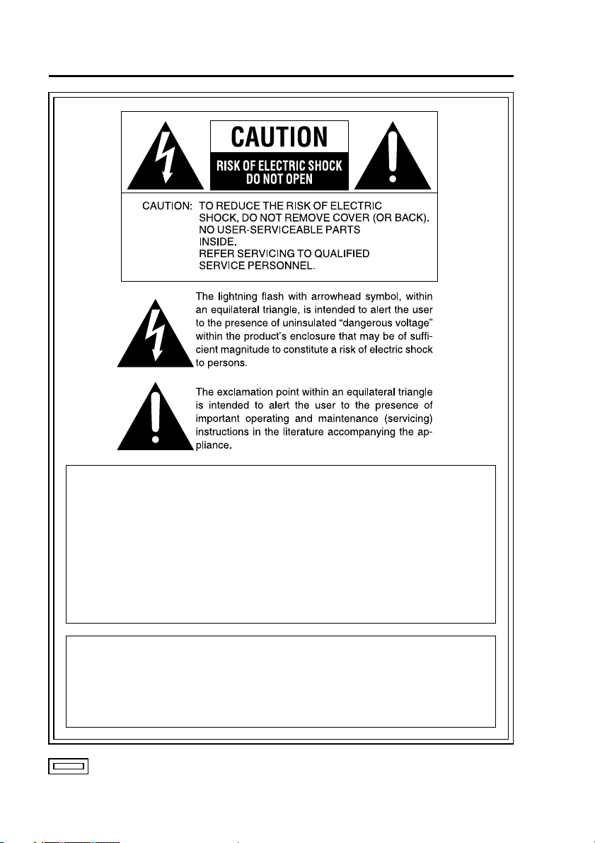
Control Reference Guide
Front panel
Before use
REC button ( )
Starts recording of video and sound
to a P2 card.
STOP button ( )
Stops recording.
P2 card slots 1, 2
Insert P2 cards here. Up to two cards
can be inserted simultaneously.
Eject button
Serves to eject a P2 card.
REC lamp
Lights up during recording. If the
combined remaining recording
time for the cards inserted in the
P2 card slots 1 and 2 is less than
30 minutes, the lamp starts to flash
(see “Indicator Lamps and Recorder
Status” on page 110).
READY lamp
Lights up when recording is possible
on a P2 card inserted in a P2 card
slot (see “Indicator Lamps and
Recorder Status” on page 110).
BUSY lamp
Lights up or flashes while a P2 card
is accessed (recording or playback;
see “Indicator Lamps and Recorder
Status” on page 110).
Lock
Locks and unlocks the P2 card slot
cover.
P2 card slot cover
Protects the P2 cards.
Recording is disabled when open.
11
Page 12
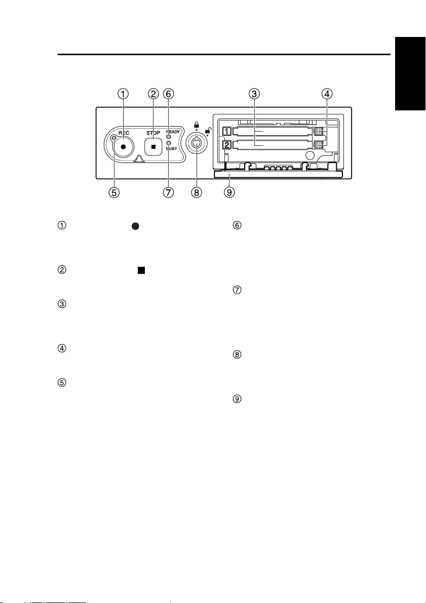
Control Reference Guide
Rear panel (1)
VIDEO OUT
AUDIO OUT
IN CAR MIC
CONTROL PANEL
GPS-ANT.
(OPTION)
(continued)
USB
AUDIO IN
CAMERA 2
CAMERA 1
IN CAR MIC connector
(Pin jack)
This is a mic level signal input.
AUDIO IN 1, 2 connectors
(Pin jack)
These are line level signal inputs.
The output signals of audio
components can be connected here.
AUDIO OUT connector
(Pin jack)
This is a line level signal output.
Accepts connection of the cable
attached to the separately sold
Remote Control Panel.
CAMERA2 connector
(Pin jack)
This is a composite signal input.
Connect a commercially available
camera.
GPIO/SERIAL
VIDEO OUT connector
(Pin jack)
This is a composite signal output.
Provides output of the video applied
to the [CAMERA1] or [CAMERA2]
connector.
Accepts connection of the cable
attached to the separately sold
Remote Control Panel.
CONTROL PANEL connector
Connect the separately sold Remote
Control Panel using the cable attached
to the Remote Control Panel.
CAMERA1 connector
Connect the separately sold Color
Camera using the cable attached to
the Camera.
12
Page 13
Control Reference Guide
Rear panel (2)
VIDEO OUT
AUDIO OUT
IN CAR MIC
CONTROL PANEL
GPS-ANT.
(OPTION)
(continued)
Before use
USB
AUDIO IN
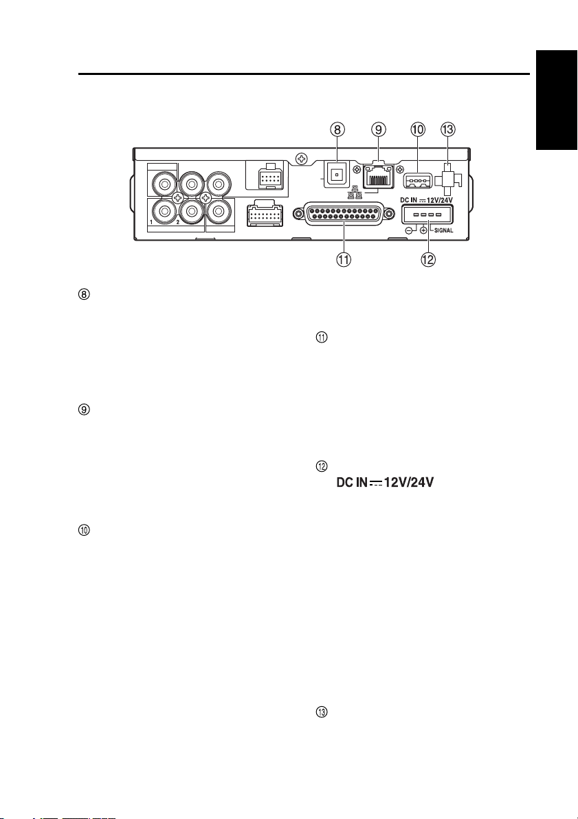
GPS-ANT. (OPTION) connector
CAMERA 2
CAMERA 1
Insert the cable from the GPS
antenna (included in the separately
sold Cable Kit). During GPS
reception, the signals received will
regularly and automatically set the
recorder clock to GPS time.
LAN connector
Connect the recorder to a PC using
a commercially available LAN cable
(cross cable).
Note:
For details on how to connect a PC,
contact your supplier.
USB connector
A commercially available USB memory
device can be connected for use as
external memory.
Not all USB memory devices may be
recognized.
Notes:
•
To protect the [USB] port, connect
the USB extension cable (included
in the separately sold Cable Kit) to
the recorder before connecting a
commercially available USB memory
device
.
• A maximum of two USB memory
devices can be connected when
using a commercially available
USB hub.
GPIO/SERIAL
• Consult your supplier for help with
connection.
GPIO/SERIAL connector
This combo connector accepts
up to eight trigger signal (GPIO1-
8) inputs, provides one recording
status output to GPIO9 and also
serves as a serial port. Connect the
trigger cable here (included in the
separately sold Cable Kit).
DC IN connector
( )
This connector accepts power from
the vehicle battery.
Connect the power cable here
(included in the separately sold
Cable Kit).
Note:
Do not pull out the power cable
while the recorder is running.
Turning the power off especially
during access (for example, during
recording) may damage the P2 card
or corrupt file management data,
setting information and other data
on the P2 card.
Cable Clamp
Use this clamp to affix video, audio,
camera cables and the power and
USB extension cables included in
the separately sold Cable Kit.
13
Page 14
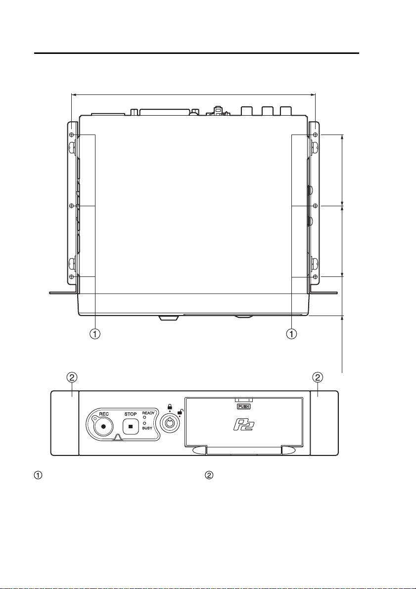
Control Reference Guide
Mounting bracket
(continued)
Top
Front
187.4
(7-3/8 inches)
<Unit : mm>
(2-5/32 inches)
55
(2-5/32 inches)
55
(1-5/32 inches)
30
Trunk mounting holes (ø3.2)
These holes are used to mount the
recorder in the trunk. Consult your
supplier and request help with
installation.
14
Spaces for center console
mounting holes
In these spaces the holes can be
made to mount the recorder on the
center console.
Consult your supplier and request
help with installation.
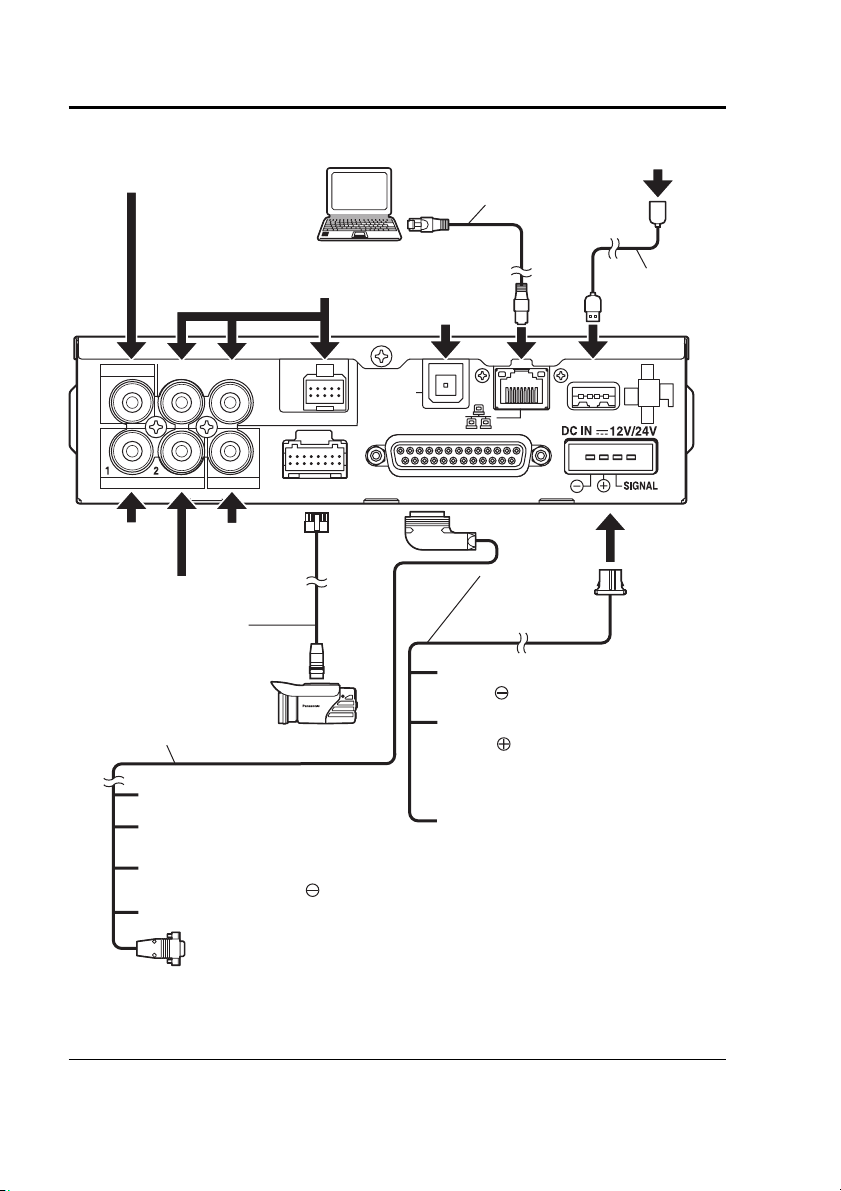
Page 15

Connections
• Be sure to consult your supplier and request installation and connection.
• Connect the red (BATT) and white (SIGNAL) wires of the power cable via a fuse
(5 A).
(The power cable is included in the separately sold Cable Kit.)
• Connect the power cable from the passenger compartment fuse box. Use a
commercially available automotive cable to provide power from the engine
compartment to operate the recorder in the passenger compartment.
• Connect the power cable when all connections are completed. Be sure to
read the instructions in the connector diagram on page 103 and the operating
instructions of the devices that will be connected.
• Verify that recording is not in progress prior to disconnecting any cables from the
recorder.
Be sure to disconnect the power cable first, and then disconnect any other cables.
• An incorrectly connected power cable could cause a fire or damage. Be sure to
connect the power cable correctly.
Before use
15
Page 16
Connections
(continued)
Audio input
(mic level)
Remote Control Panel
(separately sold)
VIDEO OUT
AUDIO OUT
IN CAR MIC
AUDIO IN
Audio input 1
(line level)
CAMERA 2
Camera
(commercially
available)
Audio input 2
(line level)
Camera cable
(provided with the
separately sold
Color Camera)
Trigger cable
(included in the separately
sold Cable Kit)
Others: Input signal lines
White:
Recording status output via
GPIO9
Black: Connect to the negative
terminal (GND: ) of the battery
Gray:
This is the input line for a signal or
vehicle speed pulse
PC
(commercially
available)
CONTROL PANEL
CAMERA 1
Color Camera
(separately sold)
∗
LAN cable (cross
cable, commercially
available)
GPS antenna
(included in the
separately sold
Cable Kit)
GPS-ANT.
(OPTION)
GPIO/SERIAL
Power cable
(included in the
separately sold
Cable Kit)
Black
(GND: )
Red
(BATT: )
: Connect to the negative
terminal of the battery
: Connect to a terminal that
always supplies power
through a fuse, regardless
of whether the engine is
on or off
White (SIGNAL):
USB memory device
(commercially available)
USB Extension
Cable (included
in the separately
sold Cable Kit)
USB
Connect the signal line
through a fuse to the
ACC line or to the
output terminal of a
timer device.
RS-232C:
Connect to a commercially
available radar gun
∗ There are two types of vehicle speed pulse signals: digital waveforms (square
waves) and analog waveforms (AC waveforms). The recorder accepts only
digital waveforms. Ask your supplier about the connection procedure.
16
Page 17
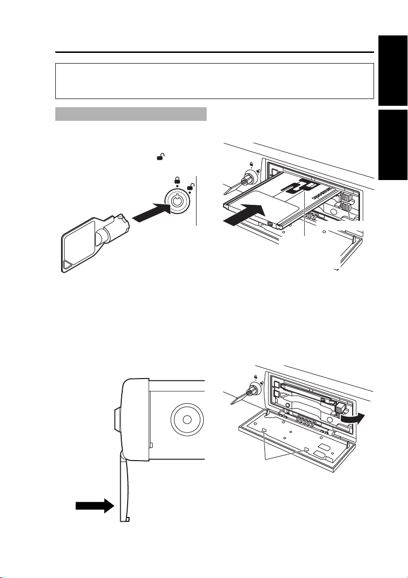
P2 card Insertion and Removal
Do not insert or remove a P2 card when another P2 card is being accessed
(while the [BUSY] lamp is lit or blinking). Otherwise the P2 card may be
damaged or P2 card data may be corrupted.
Inserting a P2 card
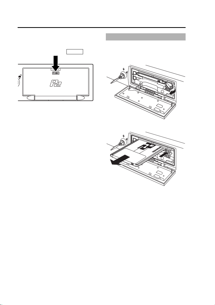
(1) Open the P2 card slot cover.
Insert the key in the lock and
turn it clockwise to [ ].
Notes:
• Do not try to turn the key further
than the stop position, and do not
move it unnecessarily, to prevent
damage to the key and lock.
• To prevent damage, do not exert
undue force on the open cover.
(2) Insert a P2 card into the P2
card slot and push it in until
the Eject button pops out.
Eject button
Insert the card
with the P2 logo
facing up.
Note:
The [BUSY] lamp blinks for a few
seconds when the P2 card slot
cover is opened. Make sure that
the blinking has stopped before
inserting a P2 card.
(3) Fold the protruding Eject
button to the right.
Before use
Operation on the Memory
Card Video Recorder
Do not push in
this direction.
Do not touch to avoid
the risk of injury.
Note:
After confirming that the Eject button
is folded over to the right, close the
P2 card slot cover. Otherwise the
Eject button will be damaged.
(Continued on the next page)
17
Page 18
P2 card Insertion and Removal
(continued)
(4) Close the P2 card slot cover.
Return the P2 card slot cover to its
original closed position and press
the section marked
When you close the P2 card slot cover
after inserting a P2 card, the [READY]
lamp indicates the recorder status (see
“Indicator Lamps and Recorder Status”
on page 110).
PUSH
.
(5) Remove the key.
Removing a P2 card
(1) Open the P2 card slot cover
(see previous page).
(2) Raise the Eject button.
(3) Push the Eject button so that
the P2 card pops out.
18
Note:
The [BUSY] lamp blinks for a few
seconds when the P2 card slot
cover is opened. Make sure that
the blinking has stopped before
removing a P2 card.
Notes:
•
If a P2 card was removed while it
was being accessed, the files may be
corrupted. Refer to “Restoring Files”
on page 71 to restore corrupted files.
• If a P2 card was removed while it
was being accessed, the P2 card
slot may be disabled. When the
recorder senses a disabled slot, it
may reboot itself automatically.
(4) Close the P2 card slot cover
(see top left of this page).
(5) Remove the key.
Page 19
Turning the Recorder On and Off
Recorder power is supplied from the vehicle’s battery.
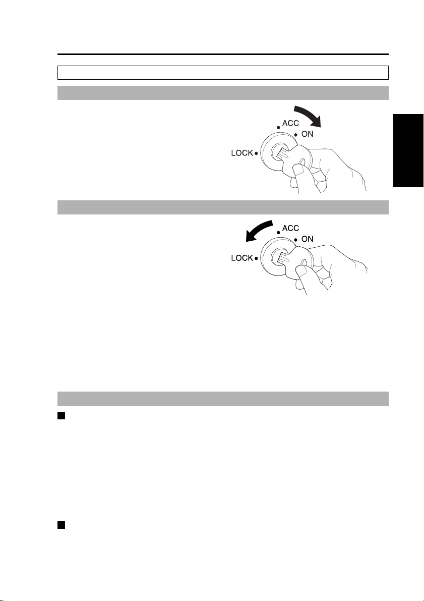
On
Turn the vehicle’s ignition switch
to ON or ACC.
Power to the recorder is turned on.
If the Remote Control Panel is
connected, its power is also turned
on.
Off
Turn the vehicle’s ignition switch
to LOCK (OFF).
Power to the recorder is turned off.
If the Remote Control Panel is
connected, its power is also turned
off.
Notes:
• The recorder cannot be turned off
from the Remote Control Panel.
• The [PowerOff Time] can be set
(see “PowerOff Time” on page 75)
to allow the recorder to continue
operating for up to 180 minutes
after the vehicle’s ignition switch is
turned to LOCK (OFF).
Operation on the Memory
Card Video Recorder
About the Internal Clock
Confirming the Time
The internal clock is set at the time of factory default. Check the time before
using, and reset the clock if necessary. (see “Date/Time” on page 79)
Note:
To use GPS, connect the GPS antenna (included in the separately sold Cable
Kit) to the [GPS-ANT.] connector on the rear panel.
Consult your supplier and request connection.
During GPS reception, the signals received will regularly and automatically set
the recorder clock to GPS time.
Time Zone Setting
The factory default time zone setting is “Eastern Standard Daylight Saving Time”.
When using in a different time zone, set the time zone for your region.
(see “TimeZone” on page 79)
19
Page 20
About the Trigger Signals
H
L
Trigger signals (GPIO1 - 8), which are
used for recording control and Color
Camera control, consist of edge and
level signals.
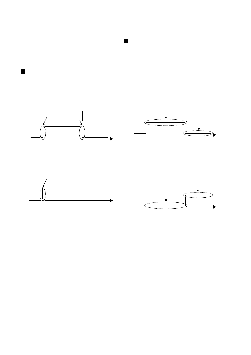
Edge signals
High-edge, low-edge and both-edge
of an edge signal can be specified.
Recording control and Color Camera
control start when a change in an edge
of the specified signal is detected.
High
Low
High-edge
Low-edge
(Time)
Both-edge
For example, when a high-edge
of “AUTOZOOM” is specified (see
“Trigger1 to 8” on page 80)
Start of AUTOZOOM
igh
ow
(Time)
:
Level signals
The high-level and low-level of a level
signal can be specified and recording
control occurs when a change is
detected in the specified signal.
When high-level is specified:
A change in the signal from low to
high starts recording and a change
from high to low stops it.
High
Low
Recording starts
(Time)
Recording
stops
When low-level is specified:
A change in the signal from high to
low starts recording and a change
from low to high stops it.
Recording stops
High
Low
Recording starts
(Time)
20
Page 21

Starting and Stopping Recording
Recording
Recording Start Methods
• Press the [REC] button (the REC
buttons on the recorder, Color
Camera and Remote Control Panel
all operate the same way)
• Apply a Recording Trigger
• When power-on recording is
enabled, recording starts when the
recorder is turned on
• Programmed Recording
(see “Programmed recording” on
pages 28, 29)
The prerecord function (see “Prerecording
and postrecording” on pages 24, 25)
records video for a pre-specified period
prior to a recording-start trigger event
(or pressing the [REC] button). The
amount of the prerecord time is set from
the Remote Control Panel. You can use
this function to prerecord video without
audio. An audio prerecord time, as well
as an audio postrecord time, can be set
independently, although it cannot be
longer than the specified video prerecord/
postrecord time.
Recording Triggers
The following types of recording
triggers are available.
• When [Action] set for detection of
trigger signals (GPIO1 - 8) is “REC”,
“CAM1REC” or “CAM2REC” and the
trigger signal is valid.
• Vehicle Speed Signal
Speed data detected by the recorder
serves as a recording trigger when
the specified speed is exceeded. This
signal is handled as an edge signal
to start recording, and is not used to
stop recording.
Select from the following detection
methods according to the intended
application or installation conditions.
Detection of own vehicle speed:
Uses the vehicle speed pulse
(see “Speedpulse” on page 84,
“Vehicle Speed Pulse Setting Table
(at 40 mph)” on pages 106, 107
and “Vehicle Speed Pulse Setting
Table (at 60 kph)” on pages 108,
109) or GPS
Target vehicle speed:
Uses a radar gun
Note:
To use the vehicle speed pulse,
GPS or radar gun as the recording
trigger, check with your supplier to
ensure that connections have been
made correctly, then specify the
source device (see “Radar/GPS” on
pages 83, 84, 85).
Notes:
• If both the vehicle speed pulse
and GPS are enabled, the vehicle
speed pulse has priority as the
recording trigger.
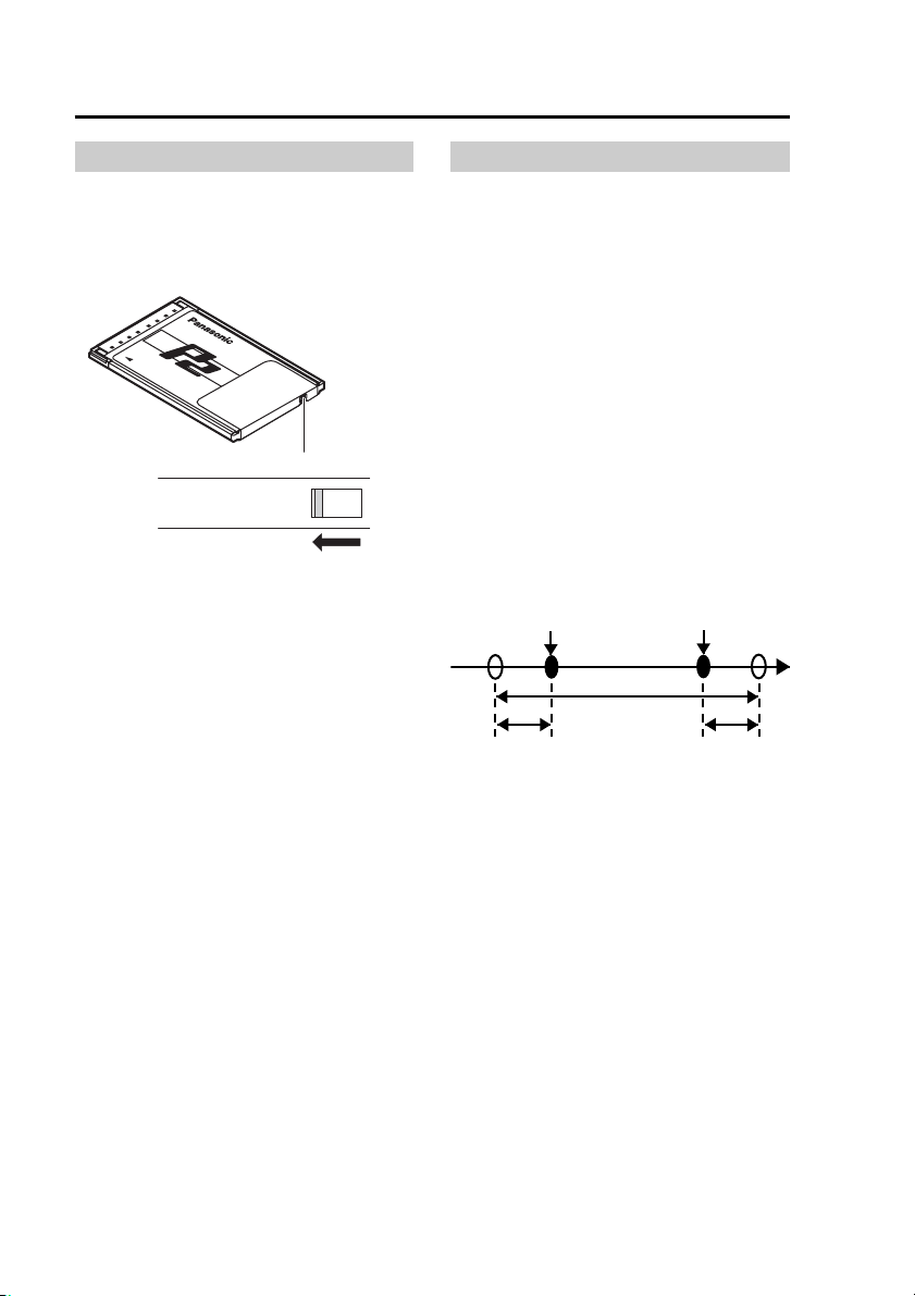
After the recording trigger is
detected by vehicle speed pulse or
GPS, if the vehicle is stopped or a
speed of 5 mph or 5 kph below the
set speed is detected, the recording
trigger can be used again.
• Recording is allowed only when
the [READY] lamp on the recorder
is lit. If pressing the [REC] button
or applying a recording trigger fails
to start recording, the [REC] lamps
on the recorder, Color Camera
and Remote Control Panel blink at
a high rate.
• The Remote Control Panel, the
Color Camera and this unit [REC]
lamps go on during recording.
Operation on the Memory
Card Video Recorder
(Continued on the next page)
21
Page 22

Starting and Stopping Recording
(continued)
• Video input at the [CAMERA1]
or [CAMERA2] connector (see
“Setup” on page 34, “Selecting
a camera” on page 55 and “Init
Camera Select” on page 75) is
recorded.
• Audio input at the [AUDIO IN 1,2]
or [IN CAR MIC] connectors (see
“Setup” on page 34, “Selecting
Audio2 input” on page 59 and “Init
Audio2 In Select” on page 75) is
recorded.
• Recording stops if the P2 card slot
cover is opened.
• Recording cannot start unless the
P2 card slot cover is closed.
• Recording will not start while the
user is configuring administrator
settings, even if the level signal
satisfies the recording start
conditions. In this case, recording
will still not start when the user
quits the administrator settings.
To start recording, the recording
start conditions must be satisfied
again after configuration of the
administrator settings is finished.
• When multiple recording triggers
are enabled, recording starts
when the first recording start
criteria are met, and if a prerecord
time has been set, the specified
period before the start event is
also recorded.
• Recording will not start under the
following conditions even if there
is space left on a P2 card.
-
When the number of files recorded
on the P2 cards inserted in slots 1
and 2 totals over 20,000 files.
- When the maximum number
of recording days on a 16 GB
or higher capacity P2 card has
been exceeded. (See “Format”
on page 86)
- When, on a single day, the
maximum number of files that
can be recorded on a 16 GB
or higher capacity P2 card has
been exceeded. (See “Format”
on page 86)
(However, when the [Rule
of Filename] is set to “WT”,
recording can be started the
next day (the next day according
to world standard time) if the
maximum number of recording
days has not been exceeded.
(see “Setup” on page 36 and
“Rule of Filename” on page 76)
Stopping Recording
Setting criteria determines when
recording stops. Settings that affect
when recording stops include the stop
timer setting for Rec Continue Time
and the presence of the recording
trigger level signal.
The following conditions are handled in
the same manner.
• When the [STOP] button on the
recorder is pressed
• When the [STOP] button on the
Remote Control Panel is pressed
• When the [REC] button on the Color
Camera is kept pressed for about 2
seconds.
• When [Action] for detection of trigger
signals (GPIO1 - 8) is set to “STOP”
and the trigger signal has reached an
active edge.
22
Page 23

Starting and Stopping Recording
(continued)
Recording Stop Criteria
Level
Stop
Signal
Timer
Setting
No No [STOP] button is
Yes [STOP] button is
Yes No [STOP] button is
Yes [STOP] button is
The postrecording function continues
to record video after the recording
stop trigger event. The amount of time
to continue recording after the stoprecording event can be set from the
Remote Control Panel.
Criteria to Stop
Recording (whichever
happened earlier)
pressed
pressed or the time set
for the stop timer of the
edge trigger recording
is reached
pressed or the level
signal changes to an
invalid level
pressed, the level
signal changes to an
invalid level, or the
signal whose level is
specified is invalid and
the stop timer setting
for the edge trigger
recording is reached
Recording stops also under the
following conditions.
• There is no more space left on the
P2 card.
•
When an administrator setup is started.
•
When an error is detected on a P2 card
and recording is no longer possible.
•
When the stop time of programmed
recording (see “Programmed recording”
on pages 28, 29) is reached.
•When a 16 GB or higher capacity P2
card is inserted and the maximum
number of recording days or files has
been exceeded.
Notes:
•
Continuous video and audio from
starting to stopping recording,
and including prerecording and
postrecording periods, are recorded
as one file on the P2 card.
• If recording time exceeds 17
hours, or if the size of one file
would exceed 4 GB, the data is
automatically split into multiple
files during recording.
• Once recording starts, it may
not be possible to stop it during
the first five seconds (approx.).
Pressing the [STOP] button during
this period causes the [REC] lamp
to blink for about one second as
recording continues.
• Pressing the [STOP] button when
recording is already stopped also
causes the [REC] lamp to blink for
about one second.
• When recording is stopped by the
stop timer at the end of the Rec
Continue Time, the postrecording
function is disabled.
• After recording is started by a
level trigger signal, it continues
for at least one minute regardless
of changes to the signal level.
During this period, you can press
the [STOP] button to interrupt the
recording.
• If the [REC] button was pressed
multiple times and the recording
trigger set as the edge signal
had multiple active edges, Rec
Continue Time is applied to the
last button press and active edge.
• Intermittent recording does not
stop due to the Rec Continue
Time.
Operation on the Memory
Card Video Recorder
23
Page 24
On Recording
Write-protect switch
The P2 card is equipped with a writeprotect switch. Sliding this switch to the
PROTECT position prevents writing
data, formatting P2 cards and deleting
files.
write-protect switch
PROTECT
Notes:
•
Any attempt to change the position
of the write-protect switch during
power-on will have no effect. To
produce the effect, turn the power off
and then turn it on again or remove
the card and then insert it again.
• If the write-protect switch is set
to the PROTECT position on any
of the cards in the two card slots,
recording will not start.
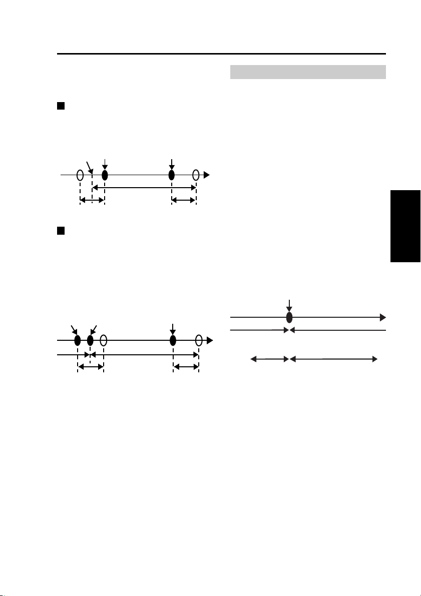
Prerecording and postrecording
Prerecording is the capability of
including material from an interval
before the specified start point in a
recording. Similarly, postrecording is
the capability of including material from
an interval after the specified stop point
in a recording.
Prerecording and postrecording times
can be set for each recording time.
Audio prerecording and postrecording
times can be set separately from video,
so prerecording and postrecording
audio may be partly omitted. Because
video prerecording and postrecording
time settings have priority, audio
prerecording and postrecording times
cannot be set longer than video
prerecording and postrecording times.
[REC] button pressed
(Recording starts)
Actual recording time
Prerecord time Postrecord time
Note:
Pressing the [STOP] button turns
off the [REC] lamp and video and
sound recordings stop when the
post record interval has elapsed.
Then the [BUSY] lamp goes off.
[STOP] button pressed
(Recording stops)
Time
24
Page 25
On Recording
(continued)
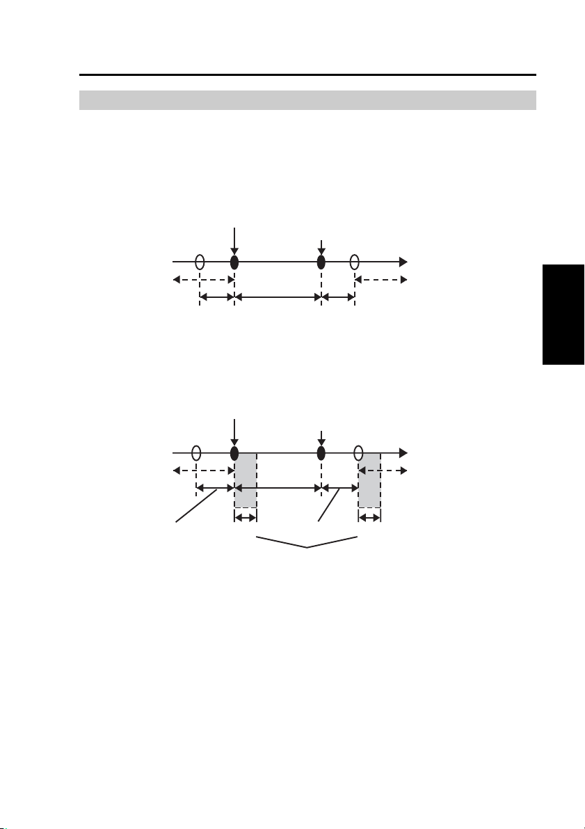
In the cases shown below, the actual
prerecord and postrecord time may be
shorter than the respective setting.
If recording is started immediately
after system startup
Prerecord time will be shorter.
Startup
completed
[REC] button pressed
(Recording starts)
Actual recording time
Prerecord time Postrecord time
[STOP] button pressed
(Recording stops)
Time
If recording is started during
postrecord interval
Postrecording will be terminated and
next recording starts. There is no
prerecording interval for the second
recording.
[STOP]
button
pressed
[REC] button pressed
(Postrecording halted and
next recording starts)
Postrecord time
Time
Actual recording time
[STOP] button
pressed
(Recording stops)
Postrecord time
Notes:
•
If you press the [REC] button and
[STOP] button alternately in rapid
succession, the system may not
separate the two recording sessions,
resulting in a single video file.
•
If the remaining capacity of the P2
card is low, the prerecord time or postrecord time may become shorter.
•
Postrecording is interrupted by
playback, trial shoot (RecCheck),
file restoration or administrator
setup.
Selecting the video source to record
You can select and record video input
at the [CAMERA1] or [CAMERA2]
connector on the rear panel of the
recorder. Also, when the action set
for the detection of trigger signals
(GPIO1 - 8) is “CAM1REC” or
“CAM2REC” and the trigger signal
is enabled, the selected video is
recorded. If prerecording is enabled
and the video source is switched by a
recording trigger, the prerecord video is
taken from the source selected before
switching, and the video is taken from
the source selected after switching. You
can select whether the video source is
switched by the recording trigger or
not, as well as selecting which video is
recorded upon switching.
Recording start trigger activation
Time
Recording of signal from
[CAMERA2] connector
Prerecording Recording after
Recording of signal from
[CAMERA1] connector
trigger activation
Notes:
• When switching video input, the
video or audio may be briefly
disrupted.
• For best results, minimize the
amount of video source switching
while recording.
Additional Information
on Operation
25
Page 26

On Recording
(continued)
Audio sources when recording
The Memory Card Video Recorder
can record up to two audio channels
(Audio1 and Audio2). Out of the
three audio input connectors on the
rear panel ([AUDIO IN 1, 2], and [IN
CAR MIC]), the signal of the source
connected to the [AUDIO IN 1]
connector will always be recorded
on the Audio1. For the Audio2, you
can select either the sound from the
[AUDIO IN 2] connector or the [IN CAR
MIC] connector. This selection is made
using the Remote Control Panel.
The following two audio recording
modes are available: INCAR and
WMIC
INCAR
Audio input at the [IN CAR MIC]
connector is recorded on the second
audio channel (Audio2).
WMIC
Audio input at the [AUDIO IN 2]
connector is recorded on the second
audio channel (Audio2).
Power-on recording
The recorder automatically starts
recording when it is powered on.
Also when the recorder is operating
with the [PowerOff Time] setting,
recording will start automatically when
the recorder is turned on.
26
Page 27
On Recording
(continued)
Intermittent recording
Intermittent recording records only one image per second extending recording
time. Entering a recording trigger during intermittent recording interrupts
intermittent recording and starts normal recording. Normal recording includes
prerecording so intermittent recording and prerecording of normal recording may
overlap during prerecording. When a recording stop criteria other than the [STOP]
button are met, intermittent recording starts after postrecording.
When a recording stop
Recording trigger input
Intermittent recording
Normal recording
Prerecording
criteria other than the
[STOP] button are met
Time
Postrecording
Under the following conditions, pressing the [STOP] button does not stop recording.
• About the first five seconds after intermittent recording transitions to normal
recording (not including prerecording)
• The first five seconds (approx.) after normal recording transitions to intermittent
recording
Intermittent recording
Normal recording
Prerecording
Recording trigger input
About 5 seconds About 5 seconds
When a recording stop
criteria other than the
[STOP] button are met
Time
Postrecording
∗
∗
When intermittent
recording is started
after postrecording,
audio is postrecorded
for the duration of
the video postrecord
time, regardless of the
∗
value set for the audio
postrecord time.
∗
When intermittent
recording is started
after postrecording,
audio is postrecorded
for the duration of
the video postrecord
time, regardless of the
value set for the audio
postrecord time.
Additional Information
on Operation
Period when recording cannot be terminated
Notes:
• When both intermittent recording and power-on recording are set to “ON”,
intermittent recording starts in the intermittent recording mode when the
recorder is turned on. (When intermittent recording mode is set to “OFF”,
normal recording starts.)
•
When recording stops after the Rec Continue Time elapses, intermittent
recording starts without activating postrecording.
• When prerecording time is set to something other than “0”, and a recording
trigger starts normal recording during intermittent recording, the prerecording
time is automatically set to start after the intermittent recording start time.
• The [REC] lamp lights during postrecording after a transition from normal to
intermittent recording.
•
The Rec Continue Time setting does not function outside of a recording trigger.
27
Page 28
On Recording
(continued)
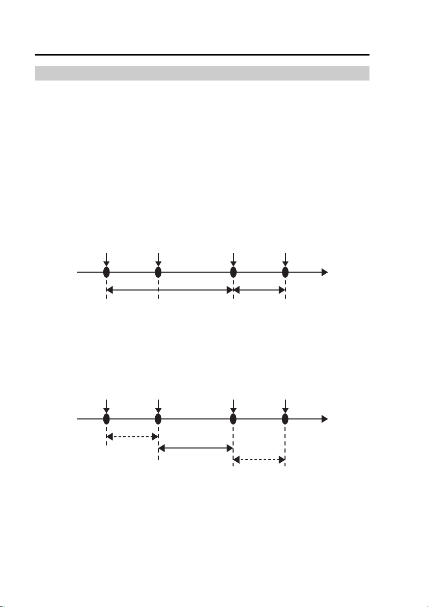
Programmed recording
Programmed recording is a function that allows you to set recording to start and
stop every day or on a specified day of the week. Programmed recording starts
and stops recording according to intermittent recording setting.
For example, when intermittent recording is set to “ON”, intermittent recording
starts at the set start time.
• Recording started by a recording trigger, which takes precedence over
programmed recording, is a normal recording. A recording started by a recording
trigger continues even if programmed recording has been set to start during this
recording interval. Programmed recording starts when a recording stop criteria
other than the [STOP] button are met during recording started by a recording
trigger. A recording started by a recording trigger is not stopped by a stop time
set using the programmed recording function.
When a recording stop
Recording trigger input
Normal recording
Programmed
recording start time
A : A normal recording file started by a recording trigger
B : A normal recording file started by programmed recording
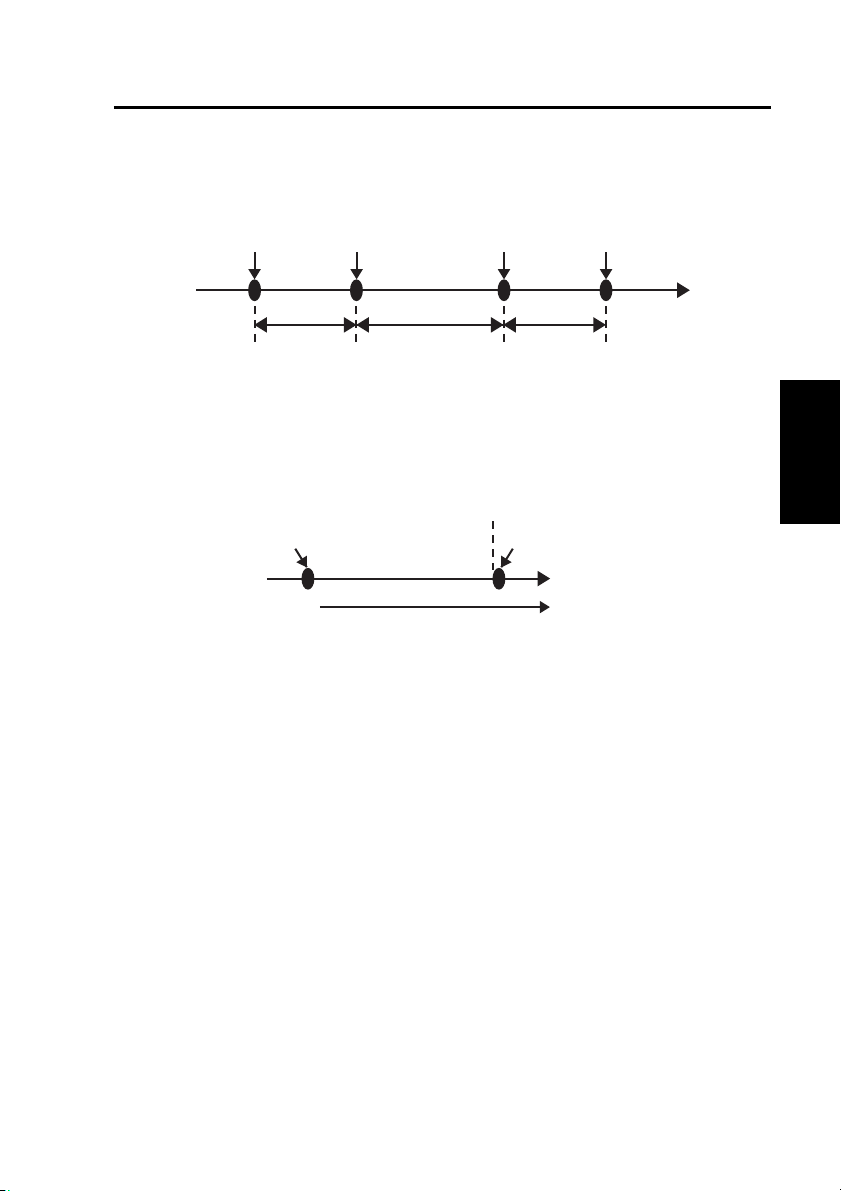
• When a recording trigger is set and both intermittent recording and programmed
recording are set to “ON”, the recording is split into intermittent and normal
recording files. In the following conditions, recording is split into three files.
criteria other than the
[STOP] button are met
Time
AB
Programmed recording
stop time
Programmed
recording start time
Intermittent recording
Normal recording
Intermittent recording
Recording
trigger input
C
When a recording stop
criteria other than the
[STOP] button are met
Time
D
Programmed
recording stop time
E
C : A intermittent recording file started by programmed recording
D : A normal recording file started by a recording trigger
E : A intermittent recording file started by programmed recording
28
Page 29
On Recording
(continued)
• If a recording trigger is set when intermittent recording is set to “OFF” and
programmed recording is set to “ON”, only normal recording occurs and the file is
not split.
Programmed
recording start time
Normal recording
Recording trigger input
C’ E’
When a recording stop
criteria other than the
[STOP] button are met
Time
D’
Programmed
recording stop time
C’ : A normal recording file started by programmed recording
D’ : A normal recording file started by a recording trigger
E’ : A normal recording file started by programmed recording
Notes:
• When the recording start time for the next day is reached during normal or
intermittent recording, normal or intermittent recording continues without
interruption.
Start time of first recording
•
If the stop time is set to the same time as the start time or before the start time, the
Monday
Time
Recording duration
stop time will be moved to the following day.
•
If the stop time and the start time on the following day are the same, the recording
will become one continuous file.
• The following settings are not available during programmed recording.
• Rec Continue Time
• Video prerecording time
• Audio prerecording time
• Video postrecording time
• Audio postrecording time
Tuesday
Start time of second recording
Additional Information
on Operation
29
Page 30
On Recording
(continued)
Changes in Intermittent recording and Programmed Recording Status
Status changes caused by button operations, recording triggers, recording stop
criteria and other inputs are shown below for set intermittent recording and
programmed recording conditions.
<When intermittent recording is set to “ON”>
Input
Status prior
to input
Recording
stop status
Intermittent
recording status
Normal
recording status
<When intermittent recording is set to “OFF”>
Status prior
to input
Recording
stop status
Normal
recording status
[STOP] button
pressed
No change
Recording
stop status
Recording
stop status
[STOP] button
pressed
No change
Recording
stop status
[REC] button
pressed
Intermittent
recording status
No change No change
No change
[REC] button
pressed
Normal
recording status
No change
When a recording stop
criteria other than the
[STOP] button are met
No change
Intermittent
recording status
Input
When a recording stop
criteria other than the
[STOP] button are met
No change
Normal recording
status
Recording
trigger input
Normal
recording status
Normal
recording status
No change
Recording
trigger input
Normal
recording status
No change
<When intermittent recording is set to “OFF”, and programmed recording is set to “ON”>
Input
Status prior
to input
Recording
stop status
Normal recording
status initiated
by programmed
recording
Normal recording
initiated by a
recording trigger
[STOP] button
pressed
No change
Recording
stop status
Recording
stop status
[REC] button
pressed
Normal recording
initiated by a
recording trigger
Normal recording
initiated by a
recording trigger
No change
When a recording stop
criteria other than the
[STOP] button are met
No change
No change
Normal recording
status initiated by
programmed recording
Recording
trigger input
Normal recording
initiated by a
recording trigger
Normal recording
initiated by a
recording trigger
No change
30
Page 31

On Recording
(continued)
Location and Name of Recording Files
The names of folders storing recording files are created according to the Rule of
Filename.
WT (world time) : “/DATA” is the base folder
LT (local time) : “/DATA /LOCAL” is the base folder
A folder indicating the recording start date is created in the above base folder and
a file indicating the recording start time is created in that folder.
For example, if recording started at 10: 23: 39 on September 28, 2006,
Name of folder storing recording files : “/DATA/20060928”
Name of recording file : “102339xn.eee”
L Local time
_
Derivative file
B Bookmark file (in WT mode)
x
M Bookmark file (in LT mode)
None No Files other than above
Additional Information
on Operation
n
.eee Extension
Derivative files are created when there are multiple file names with the same start
time.
Derivative number
(numbers are sometimes not assigned)
Names of files that have been split up automatically
The file name when the file is automatically split consists of the recording start
time to which “_n” is appended. In the file list screen, “∗” is added to the end of
the file name.
31
Page 32

On Recording
(continued)
Recording Error Warnings
When the recorder detects that it cannot properly record audio or video, it will
output the warning signals described below via GPIO9 (25-pin [GPIO/SERIAL]
connector).
Data output via GPIO9
Item
GPIO9 for Rec
GPIO9 for Error
DISABLE DISABLE
DISABLE ENABLE
When not recording
2
∗
Unlit
Continued
During
recording
Unlit
Unlit
(fast blinking when
recording error was
the prior status.)
2
ENABLE DISABLE
ENABLE ENABLE
∗
Unlit
Continued
Lit
Lit
∗
∗
(fast blinking when
recording error was
the prior status.
Otherwise Unlit.)
∗1 A recording error indicates any of the following conditions.
• Cannot record (a detailed description of examples follow)
- P2 card slot cover is open
- No recordable P2 card is inserted or it is not recognized
- No more P2 card space available
- The write-protect switch of the P2 card is set to “PROTECT”
- When an error is detected on a P2 card and recording is no longer possible
- When a new unformatted 16 GB or higher capacity P2 card is inserted
- When a 16 GB or higher capacity P2 card is inserted and the maximum
number of recording days or files has been exceeded
- When an administrator setup is started or is going on
- When [PowerOff Time] (see “PowerOff Time” on page 75) is set to “AUTO”
and the engine switch is set to the LOCK (OFF) position
• Cannot recognize video signal from the camera
∗2
Unlit
: Output to GPIO9 is low (output voltage 0 V)
∗3 Lit : Output to GPIO9 is high (output voltage 5 V)
∗4 Fast blinking: Output to GPIO9 repeatedly cycles between low → high → low
(250 ms cycle)
2
∗
2
∗
3
3
Unlit
Fast blinking
Unlit
Fast blinking
When an error
occurs
1
∗
2
∗
4
∗
2
∗
4
∗
32
Page 33

License Plate Recognition (LPR) Mode
Engaging the License Plate Recognition (LPR) mode allows you to start up the
LPR system.
Set the color camera shutter speed to [LPR Shutter Speed] (1/500 or 1/1000)
when using the LPR system.
When a recording trigger starts a recording during license plate recognition,
however, the shutter speed automatically switches to the setting configured for
[Patrol Shutter Speed].
When recording stop criteria are met, the shutter speed automatically returns to
the setting configured for [LPR Shutter Speed] (1/500 or 1/1000).
The diagram below shows how changes in LPR mode settings and starting and
stopping recording by an officer affect shutter speed, camera zoom, OSD and the
[LOCK] lamp.
[LPR Mode]
Shutter speed
Camera zoom
OSD
[LOCK] lamp
[LPR Mode] is
set to “LPR”
Prerecording
PATR OL LP R PATR OL L PR PATROL
Patrol Shutter
Speed
∗
Patrol Zoom
ON OFF ON OFF ON
LPR Shutter
LPR Zoom
Speed
Recording
trigger input
Patrol Shutter
Patrol Zoom
Speed
Blinking
Recording stop
criteria are met
(time)
LPR Shutter
[LPR Mode] is
set to “PATROL”
Postrecording
Speed
LPR Zoom Patrol Zoom
Patrol Shutter
Speed
∗ The settings available for [Patrol Shutter Speed] are AUTO, 1/100, 1/500, and
1/1000.
The settings available for [LPR Shutter Speed] are AUTO, 1/500, and 1/1000.
Note:
[Patrol Shutter Speed] and [Patrol Zoom] are available also without the license
plate recognition program. (When [Init LPR Mode] is set to “DISABLE”, or when
[Init LPR Mode] is set to “ENABLE” and [LPR Mode] is set to “PATROL”.)
Additional Information
on Operation
33
Page 34

Setup
Factory default values are shown below. Use the Remote Control Panel to change
settings. When running a PC application, the set value may be altered, or the
items that can be set may be restricted.
Items officers can set:
Setting Item
Camera Color camera setting
1
AE[-2 -- +2] 0 Color camera video brightness setting
LPR Mode PATROL LPR mode setting
LPR Shutter
Speed
LPR Zoom 1.0 Zoom ratio setting with [LPR Mode] set to
Patrol Shutter
Speed
Patrol Zoom 1.0 Zoom ratio setting with [LPR Mode] set to
Audio Audio setting
2
Audio2 Select INCAR Audio2 input selection
Audio1 ON Audio1 playback sound setting
Audio2 ON Audio2 playback sound setting
Setup/Info Setup/Information
3
Officer Officer settings
Officer 1 ID ---- Officer 1 ID
Officer 1 first name
Officer 1 last name
Officer 2 ID ---- Officer 2 ID
Officer 2 first name
Officer 2 last name
Operation Key
Lock
On Screen
Type
Camera LED ON Color camera [REC] lamp setting
Factory Default Value
1/1000 Shutter speed setting with [LPR Mode] set
AUTO Shutter speed setting with [LPR Mode] set
---- Officer 1 first name
---- Officer 1 last name
---- Officer 2 first name
---- Officer 2 last name
OFF Lock of buttons by an officer
OFF Overlay OSD setting
Description
Setting : -2, -1, 0, +1, +2
Setting : LPR (License Plate Recognition
mode), PATROL (normal mode)
to “LPR”
Setting : AUTO, 1/500, 1/1000
“LPR”
Setting : 1.0 - 22.0
to “PATROL”
Setting : AUTO, 1/100, 1/500, 1/1000
“PATROL”
Setting : 1.0 - 22.0
Setting : INCAR, WMIC,
LINK CAM
Setting : ON, OFF
Setting : ON, OFF
Setting : ON, OFF
Setting : AUTO, SIMPLE, DETAILS, OFF
Setting : ON, OFF
34
Page 35

Setup
(continued)
Items administrators can set:
Setting Item
Rec/Play Recording and Playback Settings
1
PowerOff Time
Factory Default Value
1
∗
120 Time from the SIGNAL turn-off to recorder
Description
shut-down (minutes)
Init Camera
Select
Init Audio2 In
Select
Setting :
1 Initial video input selection (upon power on)
Setting :
LAST
INCAR Initial source selection for Audio2 input
(upon power on)
Setting : INCAR ([IN CAR MIC] connector input)
LINK CAM
LAST
0, 10, 20, 30, 60, 90, 120, 180,
2
∗
AUTO
1 ([CAMERA1] connector input)
2 ([CAMERA2] connector input)
3
∗
4
∗
WMIC
([AUDIO IN 2] connector input)
5
∗
3
∗
PowerOn Rec OFF Automatically start recording with power-on
Setting : ON, OFF
Loop Rec OFF Loop recording
Setting : OFF fixed
Intermittent Rec OFF Intermittent recording
Setting : ON, OFF
Resolution/
RecRate
Q-512k Recording resolution and bit rate
Setting : Q-512k (320x240 pixel, 512 kbps)
Q-1M (320x240 pixel, 1 Mbps)
F-1M (720x480 pixel, 1 Mbps)
F-2M (720x480 pixel, 2 Mbps)
F-1M is 10 fps, and others are 30 fps
(Continued on the next page)
∗1 Depending on the vehicle, the battery may run out of power during operation.
∗2 When recorder operation is not controlled by a PC application:
Power is turned off immediately. Note, however, that power is not turned
off while data is exported to a USB memory device, but is turned off after
completion of data export.
When recorder operation is controlled by a PC application:
Power is turned off when control from a PC application is released, or when
the PC card slot cover is opened.
∗3 Applies the setting in effect when power was last turned off. Unless power is
turned off properly, the operating state may not be saved correctly.
∗4 WMIC is the abbreviation for Wireless Microphone.
∗5 In LINK CAM mode, being linked with the change of camera, Audio2 sound
input changes. Changing to the [CAMERA1 (CAMERA2)] connector input,
sound comes from the [AUDIO IN 2 (IN CAR MIC)] connector input.
Additional Information
on Operation
35
Page 36

Setup
(continued)
Setting Item
1 Rec Continue
Time
Factory Default Value
Description
CONTINUE Continuous recording time (minutes)
Setting : 1, 2, 5, 10, 15, 20, 30, 60, 90,
CONTINUE
PreRec Time
(Video)
PreRec Time
(Audio)
PostRec Time
(Video)
PostRec Time
(Audio)
Rule of
Filename
90 Video Prerecord time (seconds)
Setting : 0, 10, 20, 30, 60, 90
90 Audio Prerecord time (seconds)
Setting : 0, 3, 10, 20, 30, 60, 90
90 Video Postrecord time (seconds)
Setting : 0, 10, 20, 30, 60, 90
90 Audio Postrecord time (seconds)
Setting : 0, 3, 10, 20, 30, 60, 90
WT Recording file naming method
Setting : WT(World time)
LT(Local time)
Init Audio2 Rec ON Initial on/off setting for Audio2 input (upon
Init On Screen
Type
OFF
power on)
Setting : ON, OFF, LAST
Initial OSD (on-screen display) overlay setting
Setting : AUTO, SIMPLE, DETAILS, LAST
2
∗
2
∗
OFF
GPIO9 for Rec ENABLE Select recording status output to GPIO9
Setting : ENABLE, DISABLE
GPIO9 for Error ENABLE
Select recording error status output to GPIO9
Setting : ENABLE, DISABLE
Init Audio Out
(Play)
Play Mode SINGLE
BOTH
Initial audio output selection (upon power on)
Setting : OFF, 1, 2, BOTH, LAST
2
∗
Select playback mode (relay playback setup)
Setting : SINGLE, RELAY
Skip Target Skip position
Trigger/Marker
YES Select a trigger or marker location
Setting : YES, NO
Head of File YES Select the starting point of the file
Setting : YES, NO
2 Programed Rec
Daily –
Programmed recording setting
Programmed recording for every day
Setting : –, ON
(Setting “–” will disable start and stop time settings)
Mon to Sun –
Programmed recording setting on a specific
day of the week (Monday to Sunday)
4
∗
Setting : –, ON
(Setting “–” will disable start and stop time setting
s
)
∗2 Applies the setting in effect when power was last turned off. Unless power is
turned off properly, the operating state may not be saved correctly.
∗4 When [Daily] is set to “ON”, [Mon to Sun] cannot be set.
,
36
Page 37

Setup
(continued)
Setting Item
3 Date/Time Date, Time and Time Zone Settings
TimeZone Eastern
Style ISO Date display format setup
Date/Time Current time Year/Month/Day Hour:Min.:Sec.
4 Trigger Trigger Signal (GPIO1-8) Settings
GPIO ON All GPIO input or no input
Action NONE
Factory Default Value
Standard
Daylight
Saving
Time
Description
Time zone
Hawaii Standard Time,
Yukon Standard (Daylight Saving) Time,
Pacific Standard (Daylight Saving) Time,
Mountain Standard (Daylight Saving) Time,
Central Standard (Daylight Saving) Time,
Eastern Standard (Daylight Saving) Time,
Atlantic Standard (Daylight Saving) Time,
Asia Tokyo
Setting :
Setting :
Action upon trigger signal (GPIO1-8) detection
Setting :
CAM1 (selects [CAMERA1]
CAM2 (selects [CAMERA2]
NONE (no operation)
ISO (YYYY-MM-DD HH:MM:SS format),
USA (MM/DD/YYYY HH:MM:SS format)
ON (All GPIO input permission), OFF
REC, STOP,
AUTOZOOM
CAM1REC (records video input to the
CAM2REC (records video input to the
CAM1LED Changes the status setting
(automatically zooms in/
out or pauses)
connector input)
connector input)
[CAMERA1] connector )
[CAMERA2] connector)
(on/off) of the [REC] lamp on
a Color Camera connected to
the [CAMERA1] connector.
Additional Information
on Operation
(Continued on the next page)
37
Page 38

Setup
(continued)
Setting Item
Detection H
4
Printable OFF Character definition when one letter is
5 OSD
OSD ON OSD on/off setting
Display Position L-Upper Location display setting
Trigger ON OSD setting during trigger signal (GPIO1-8)
Time ON Date and time display setting
Source@Area OFF Display setting for the vehicle identification
Factory Default Value
Description
Method for trigger signal (GPIO1-8) detection.
Choice of signal detection depends on set
[Action].
• In REC, CAM1REC and CAM2REC modes
Setting : H (high-edge trigger),
Level H (high-level trigger),
L (low-edge trigger),
Level L (low-level trigger),
B (both-edge trigger)
In CAM1, CAM2 CAM1LED, AUTOZOOM and
•
STOP modes
Setting : H (high-edge trigger),
L (low-edge trigger),
B (both-edge trigger)
• In NONE mode
Setting : H (high-edge trigger),
L (low-edge trigger),
SPEED
displayed in the OSD
Setting : A - Z, –, OFF
Embedded OSD (On Screen Display)
Setting : ON, OFF
Setting :
R-Upper (upper right),
L-Bottom (bottom left),
R-Bottom (bottom right)
input
Setting : ON, OFF
Setting : ON, OFF
and name of a location
Setting : ON, OFF
L-Upper (upper left),
(vehicle speed pulse, GPIO8 only)
38
Page 39

Setup
(continued)
Setting Item
6 Camera
Factory Default Value
Description
Color Camera setting
Zoom Limit 22 Maximum zoom magnification
Setting : 22, 220
AGC Level HIGH
Color Camera automatic gain control setting
Setting : LOW, MID, HIGH, OFF
Init Backlight OFF Initial backlighting compensation setting
(upon power on)
Setting : ON, OFF, LAST
2
∗
(perform backlighting compensation
when on)
Init AE Shift 0 Initial exposure compensation of Color
Camera video (upon power on)
Setting : -2, -1, 0, +1, +2, LAST
Flip OFF
Color Camera image top/bottom flip enable/
5
∗
2
∗
disable
Setting : ON (Top/bottom flip enabled),
OFF (Top/bottom flip disabled)
AutoZoom
Magnification
10 Magnification of auto zoom
Setting : 1, 2, 3, 4, 5, 7, 10, 15, 22
AutoZoom Time 3 Auto zoom magnification retention time
(seconds)
Setting : 3, 5, 8
Init Camera LED ON Initial Color Camera [REC] lamp enable/
disable setting (upon power on)
Setting : ON ([REC]lamp lights during recording),
LAST
OFF
([REC]lamp does not light),
2
∗
Init IR Mode AUTO IR switching function
Setting :
AUTO
(Automatically switch IR
function on/off),
OFF (Force IR function off),
ON (Force IR function on),
LAST
IR Level LOW IR auto switching level setting
2
∗
6
∗
Setting : LOW, HIGH
IR Time 30 IR auto switching level detection time
(seconds)
6
∗
Setting : 10, 30, 60, 300
(Continued on the next page)
∗2 Applies the setting in effect when power was last turned off. Unless power is
turned off properly, the operating state may not be saved correctly.
∗5
When the [Init AE Shift] setting is “+2” and the target is dark, the image may not
refresh at 30 frames/sec.
∗6
The [IR Level] and [IR Time] settings apply only when the [Init IR Mode] setting
is “AUTO”.
Additional Information
on Operation
39
Page 40

Setup
(continued)
Setting Item
6 AUTO FOCUS PRESET Select color camera focusing method when,
Init LPR Mode DISABLE LPR (License Plate Recognition) function
Factory Default Value
Description
• [Init LPR Mode] is set to “DISABLE”
• [Init LPR Mode] is set to “ENABLE” and
[LPR Mode] is set to “PATROL”
• a recording trigger starts recording when
[Init LPR Mode] is set to “ENABLE” and
[LPR Mode] is set to “LPR”
Setting :
AUTO (set to auto focus when zoom
PRESET (When the zoom is 3x or below, the
DISABLE
switching
Setting :
ENABLE (LPR function is on),
DISABLE (LPR function is off and [LPR
ratio has been changed.),
camera is focused at a distance of
about 15 m (50 feet). Subsequent
zooming will engage auto focus.),
(Focus is locked at a distance
of about 40 m (130 feet) and
auto focus is disabled.)
Mode] switches to “PATROL”.)
40
Page 41

Setup
(continued)
Setting Item
Management
7
Factory Default Value
Description
Officer management setup
Mode
Setting Method AUTO Officer registration procedure
Setting : AUTO, MANUAL, LIST
Operation Key
Lock
Radar/GPS Radar Gun, GPS and Speed Settings
8
Baud Rate 4800 Radar Gun communications rate (bps)
OFF Lock of buttons by an administrator
Setting : ON, OFF
7
∗
Setting : 1200, 2400, 4800, 9600, 19200,
38400
7
Bit Length 8 Radar Gun communications data bits
∗
Setting : 7, 8
7
Stop Bit 1 Radar Gun communications stop bits
∗
Setting : 1, 2
7
Parity NONE Radar Gun communications parity
∗
Setting : NONE, ODD, EVEN
Model Select ProLaser3
Connection of
OFF Radar Gun connection
Radar
Connection of
VPU GPS connection
GPS
Radar gun type selection
Setting : ProLaser3
Others_Analyzed_PC
8
∗
∗
8
∗
7
Setting : VPU(Recorder), OFF
Setting : VPU(Recorder), PC, OFF
Collection Time 5 Interval for GPS Data Collection (seconds)
Setting : 1, 2, 5, 10
Geodetic System WGS84
Geographical coordinate system setting
Setting : WGS84, TOKYO
Speedpulse at
Std Speed
Own Speed OFF
20
Number of vehicle speed pulses per second
at 60 kph or 40 mph
Setting : 5 - 400
9
∗
Own vehicle speed at which recording starts
Setting : OFF, 1 - 500
Target Speed OFF
Target vehicle speed at which recording starts
Setting : OFF, 1 - 500
Speed Unit MPH Speed measurement units
Setting : MPH(M/H), KPH(Km/H)
CAM Select in
Speed
NO CHANGE
Camera selection when speed is exceeded
Setting : 1, 2, NO CHANGE
∗7 When using a radar gun, contact your supplier.
∗8 Only the first 8 characters appear in the [Model Select] input field.
∗9 The number of pulses is obtained and set from the “Vehicle Speed Pulse
Setting Table” (see “Vehicle Speed Pulse Setting Table (at 40 mph)” on
pages 106, 107 and “Vehicle Speed Pulse Setting Table (at 60 kph)” on
pages 108, 109) based on tire outside diameter and the number of pulses
per wheel rotation. Verify that the set value is correct during actual driving.
The outside diameter refers to the actual tire, and not rim size.
41
Additional Information
on Operation
Page 42

Setup
(continued)
Setting Item
9 Auto
Maintenance
Operation OFF Auto maintenance operation setting
Interval 6
Day (week) 1st Week setting
Day
(day of the week)
Time (hour) 0
Time (minute) 0 Start time (minute) setting
Factory Default Value
Mon Day of the week setting
Description
Auto maintenance interval and date setting
Setting : ON, OFF
Interval setting (months)
Setting : 1, 3, 6, 12
Setting : 1st, 2nd, 3rd, Last
Setting : Mon, Tue, Wed, Thu, Fri, Sat, Sun
Start time (hour) setting
Setting : 0 – 23
Setting : 0 – 59
42
Page 43

Text Files Used with the Recorder
The following types of text files can be used by the recorder, and created with a
commercially available text editor.
To display correctly, the files must meet the following specifications. Refer to “Sample
Files” on pages 45, 46 for examples.
File Types
File Types Contents File Name
Officer Data File This file type contains officer settings. It is
Officer
Registration File
Administrator
Registration File
Event Type File
required when the officer data setting method
is “AUTO” or “MANUAL”. It is also used for
log-in authentication on the administrator
settings screen.
This file type contains batch officer registration
data (for up to 500 officers) for the recorder.
When the “LIST” officer data setting method is
selected, officers can select their own names
from the registration list to load their settings
into the recorder.
This file type contains administrator registration
data (for up to 10 administrators) that enables
logging in to the administrator settings screen.
An officer data file is required for log-in
authentication on the administrator settings
screen.
File used to store event types on the recorder.
\WIDKEY\
WID∗∗∗∗∗.TXT
\WIDKEY\
WOFFICER.TXT
\WIDKEY\
WADMIN.TXT
\WIDKEY\
EVTYPE.TXT
Additional Information
on Operation
Note:
When the officer or administrator registration file is as follows, officer or
administrator data is not registered, but is deleted along with previously
registered officer and administrator data.
• When no officer or administrator data is present
• When the content of required items is invalid
Saving Location and File Naming
Text files to be used on this unit must be stored in a “WIDKEY” created under the
root directory of a USB memory device.
Be sure to save the Officer Data File to one USB memory device.
Officer data file names are composed of up to eight characters beginning with the
prefix “WID”, and having the extension “.TXT”. There are no restrictions on naming
other than the “WID” prefix.
When multiple officer data files are saved in the “WIDKEY”, the file names are
automatically sorted (in ascending order), and the first 1 or 2 files are used as
officer data.
43
Page 44

Text Files Used with the Recorder
File Specifications
(continued)
Syntax:
Officer data files may contain no more than one statement per line.
Multiple statements or definitions on one line are invalid.
Line Feed Codes:
Line feeds are coded as the hexadecimal values 0Dh 0Ah or just 0Ah.
Blank Lines:
Blank lines are ignored. Aside from the line feed code, a blank line may contain
only space and tab (09h) characters.
Comment Lines:
Lines beginning with “#” (ignoring leading spaces or tabs) are considered to
be comment lines. These have no special meaning, but may contain notes or
descriptions. Valid comment characters are those from 20h to 7Eh.
Definition Lines:
• An identifier is a definition value.
• These lines define names and other data. Leading spaces and tabs are ignored.
• Identifier descriptions are shown in the following table.
◎ : Required item ○ : An item with significance or an object of inspection × : Ignored item
Identifier
FirstName 50 Specify officer's first name
MiddleName 1 Specify officer's middle initial
LastName 50 Specify officer's last name
ID 50
Password 12
SDate 10 Shift start date YYYY-MM-DD
STime 5 Shift start time hh:mm
EDate 10 Shift end date YYYY-MM-DD
ETime 5 Shift end time hh:mm
Shift 10
Area 10 Name of a location
Source 50 Vehicle identification
Border 73
Max.
characters.
Officer number for authentication
This should be entered when
making administrator settings.
A term for a work period, for
example, early shift.
Borders may be assigned
to multiple officers. Defined
values are ignored. For use
within registration files.
Description
Officer Data File
Officer 1 Officer 2 Officer
◎◎◎◎
○○○○
◎◎◎◎
◎◎◎◎
○○×○
○×××
○×××
○×××
○×××
○×××
○×××
○×××
××○○
Officer/Administrator
Registration File
Administrator
Identifier
EvTypeN 99
Max.
characters.
44
Description Event Type File
Defines event type N.
(N is a number between 1 and 10.)
○
Page 45

Text Files Used with the Recorder
• If no definition is provided for a required item (that is, it is undefined), necessary
data is considered to be incomplete and invalid for registration or testing.
Identifiers are not case sensitive.
• All item definition values are character strings consisting of alphanumeric
symbols other than “<” (3Ch), “>” (3Eh), “\” (5Ch), “&” (26h) and “,” (2Ch), control
character codes 00h to 1Fh, and “Delete” character code 7Fh. Characters
(including spaces) following “=” on a line are considered to be the definition
value. Any invalid characters are handled as spaces. Characters exceeding the
maximum character length are ignored.
• Identifiers having no defining characters are considered to be undefined. For
example, if a line contains a “=” followed by a line feed character, that identifier
is considered to be undefined. If an identifier is multiply defined on different lines,
the last definition line has priority.
Sample Files
Officer data file:
(continued)
FirstName=John
#MiddleName=
LastName=Smith
ID=ICV12345
Password=panasonic
SDate=2005-09-12
STime=08:15
#EDate=2005-09-12
#ETime=20:00
Shift=Patrol
Area=WEST
Source=Car123
# Structure of officer information file
# Identifier Max. Chars. Description
# FirstName 50 Specify officer's first name
# MiddleName 1 Specify officer's middle initial
# LastName 50 Specify officer's last name
# ID 50 Officer name for authentication
# Password 12 Password required to register as administrator
# SDate 10 Shift start date YYYY-MM-DD
# STime 5 Shift start time hh:mm
# EDate 10 Shift end date YYYY-MM-DD
# ETime 5 Shift end time hh:mm
# Shift 10 A term for a work period
# Area 10 Name of a location
# Source 50 Vehicle identification
Additional Information
on Operation
45
Page 46

Text Files Used with the Recorder
Officer Registration File :
# John Smith
FirstName=John
MiddleName=
LastName=Smith
ID=ICV12345
Border=------------------------------------
# Jane White
FirstName=Jane
MiddleName=
LastName=White
ID=ICV12346
Administrator Registration File :
# Mike Brown
FirstName=Mike
MiddleName=
LastName=Brown
ID=ICV12347
Password=panasonic
(continued)
Event Type File :
EvType1=FOOTBALL
EvType2=BASEBALL
EvType3=HOCKEY
EvType6=TENNIS
EvType10=GOLF
# Defines event type file format
# Identifier
# EvTypeN 99
Max.characters.
46
Description
Defines event type N (N is a number between 1 and 10.)
Page 47

Control Reference Guide of the Remote Control Panel
Front panel
REC lamp
R E T U R N
M E N U
C O N T R O L P A N E L
O N /
O F F
LCD panel
Shows images and operation menus.
1, 2
AUTO ZOOM button
Provides automatic control of zoom-in,
pause and zoom-out operation.
The officer can set zoom ratio and
pause time. (see “Zooming” on page 55)
BOOK MARK button
Press during recording or playback
to enter bookmarks. A set bookmark
displays an icon
for 1 to 2 seconds when pressed.
(see “Adding bookmarks” on pages
64, 67)
Backlight compensation button
1, 2
∗
( )
Press to compensate for strong
backlighting. This button toggles
between ON and OFF at each press.
(see “Making a backlit image easier
to view” on page 55)
Zoom buttons
Use these buttons to zoom out (Wbutton) and zoom in (T-button).
(see “Zooming” on page 55)
∗
2
∗
on the display
1, 2
∗
Lights or flashes during recording.
(see “Indicator Lamps and Recorder
Status” on page 110)
2
REC button
∗
Press to start recording video and
sound to P2 card. (see “Starting
recording” on page 63)
2
STOP button ( )
∗
Stops recording. (see “Stopping
recording” on page 63)
AUDIO2 MUTE button/lamp
Starts/releases recording for Audio2.
Pressing this button turns the lamp
on/off. While the lamp is lit, Audio2
is not being recorded. (see “To mute
Audio2 input sound” on page 55)
1
IR MODE button
∗
Switches the IR mode to one of the
following modes.
AUTO
:
Automatically changes IR mode
depending on ambient brightness.
ON: Turns on the IR mode.
OFF: Turns off the IR mode.
CAMERA SELECT button
Each press of the button toggles the
recorder between the [CAMERA1]
and [CAMERA2] connector inputs.
(see “Selecting a camera” on page 55)
Volume control buttons ( )
Adjusts speaker sound volume.
Brightness buttons ( )
Adjusts LCD panel brightness.
Additional Information
on Operation
Operation Using the Remote
Control Panel (separately sold)
∗1
A commercially available camera connected to the [CAMERA2] connector cannot be controlled.
∗2
The lamp turns on when the [CONTROL PANEL ON/OFF] button is set to ON.
47
Page 48

Control Reference Guide of the Remote Control Panel
(continued
)
Front panel
RETURN button
R E T U R N
M E N U
Returns to the previous menu or
screen. (see “Returning to previous
screen” on page 51)
C O N T R O L P A N E L
O N /
O F F
CONTROL PANEL ON/OFF button
Turns on and off he LCD panel, lamp
indications and buttons when the
Memory Card Video Recorder is on.
It cannot turn on or off the Memory
Card Video Recorder or this unit
(see “Turning off the LCD panel” on
page 55).
LIVE/ARCHIVE button
Switches between the live and
playback screen. (see “Viewing Live
Video” on page 55 and “Playback”
on page 65) Press this button to
open the Live screen when the
“Information” screen, “Archive”
screen, “Restore” screen, Officer
setup top screen or Setup/Admin
top screen is displayed (see “Menu
List” on pages 93 - 102).
Skip back button ( )
Press to return playback to the
previous skip location. (see “Moving
back to a previous skip location to
start playback” on page 66)
Skip forward button ( )
Press to move playback the next
skip location. (see “Moving to the
next skip location to start playback”
on page 66)
MENU button
Opens menus on the LCD panel.
Cursor buttons
( , , , , )
Use these buttons to manipulate
menus and control playback.
• During menu operation
] :
[
[ , , , ] :
• During playback
[
[
[
[
[ ] : Press to fast forward.
Each press changes the fast
Press the center position of
the button to confirm an entry.
Press to move the
cursor or change a
set value.
] : Press the center position of
the button to toggle between
playback and pause.
] : Press to return to a playback
position that is 7 seconds
earlier.
] : Engages slow playback. Each
press changes playback
speed between 1/10 and 1/2.
] : Press to rewind.
Each press changes the rewind
speed from x4 to x20 and x200.
forward speed from x4 to x20
and x200.
48
Page 49

Control Reference Guide of the Remote Control Panel
(continued)
Front panel
RETURN
CONTROL PANEL
BUSY lamp
Lights or blinks when accessing
a P2 card (for example during
recording and playback). (see
“Indicator Lamps and Recorder
Status” on page 110)
READY lamp
Lights, flashes or goes off to indicate
whether or not a P2 card can be
recorded. (see “Indicator Lamps and
Recorder Status” on page 110)
MENU
ON/
OFF
Rear panel
Speaker
In playback screen mode:
In Live screen mode:
The audio sound track
Outputs audio. However,
during [
[
] slow playback,
] rewind, and [ ] fast
forward, audio is not output.
is not normally available.
For how to monitor the
audio, refer to “Checking
audio” on page 59.
Operation Using the Remote
Control Panel (separately sold)
LOCK lamp
When lit:
Indicates whether or not buttons
other than the [REC], [MENU],
[CONTROL PANEL ON/OFF] and
[RETURN] buttons are locked.
When blinking:
Indicates that the license plate
recognition mode is running.
For details, refer to “License
Plate Recognition (LPR) Mode”
on page 33.
Anchoring groove
Provides attachment for a commercially
available stand.
Securing screw holes
Use the supplied screws to attach
a commercially available mounting
bracket.
49
Page 50

Basic Menu Operations
For a list of all the menus, refer to “Menu List” on pages 93 - 102.
(This list also describes menus available only to administrators.)
Example: Audio1 Test
1. Press the [MENU] button.
The Menu appears.
A triangle displayed at the right
edge of a menu item indicates that
it contains a submenu.
Menu
Camera
RecCheck
Audio
Archive
Setup/Info
Restore
4. Use the [ , ] buttons to select
[Audio1 Test].
Audio
Audio2 Select
Audio1 Test (Press ENTER Key)
Audio2 Test (Press ENTER Key)
Press the [ ] button to confirm
5.
INCAR
the entry.
The Audio1 test is now ready to run.
2. Use the cursor buttons [ , ]
to select an item.
Menu
Camera
RecCheck
Audio
Archive
Setup/Info
Restore
3. Press the center position of
the cursor button [ ] or [ ]
to confirm the entry.
The selected item opens to reveal
selection details.
Audio
Audio2 Select
Audio1 Test (Press ENTER Key)
Audio2 Test (Press ENTER Key)
INCAR
Use the [ , , , ] buttons to
set a value.
• A selected item with tiny triangles
at the top and bottom allow you to
change its value by pressing [
].
or [
(Screen example)
Trigger
GPIO
Trigger1
Trigger2
Trigger3
Trigger4
Trigger5
Trigger6
Trigger7
Trigger8
Action
NONE H
NONE H
NONE H
NONE H
NONE H
NONE H
NONE H
NONE
Detection
• A selected item with tiny triangles
to the left and right allow you to
change its value by pressing [
].
or [
(Screen example)
AE[-2 -- +2]
0
ON
Printable
OFF
OFF
OFF
OFF
OFF
OFF
OFF
H OFF
]
]
50
Page 51

Basic Menu Operations
Returning to previous screen
Press the [RETURN] button to return
to the previous screen. The menu is
cleared when the “Archive” screen,
Officer setup top screen or Setup/
Admin top screen is displayed.
Long menus
Menus with arrows at the top and
bottom contain items that are
currently not shown.
(continued)
Operation Using the Remote
Control Panel (separately sold)
51
Page 52

Setting up/Deleting Officer Data
When a PC application is running,
this unit freezes in the live screen
and officer data cannot be set or
deleted.
Before using this unit, you must create
and configure officer data, such as an
officer ID and officer name. For details
on creating officer data, refer to “Text
Files Used with the Recorder” on
pages 43 - 46.
Three setup methods are available, called
the AUTO, MANUAL and LIST modes.
Check with the administrator which
mode is selected. (see “Setting Method”
on page 83)
Note:
Starting up a PC application during
officer data setup will abort the
setup operation. The recorder will
then freeze in the live screen and
disable setup and deletion of officer
data.
AUTO mode
When a USB memory device is
connected to this unit, or when
connection is detected after turning
power on, the officer data for one or
two officers is automatically read in
and activated (see “Text Files Used
with the Recorder” on pages 43 - 46).
Connect a USB memory device
containing officer data to this
unit.
The [READY] lamp flashes for
one second:
This indicates that the data was
correctly read.
The [BUSY] lamp flashes for one
second:
This indicates that the data could
not be correctly read.
Disconnect the USB memory
device and then reconnect it. If
the [READY] lamp does not flash
52
when the USB memory device
is connected again, check if the
officer data file has been correctly
saved to the USB memory device.
If the above measures do not
correct this problem, replace the
USB memory device.
Notes:
•
If a USB memory device is connected
and the officer data is read during
recording, the file will be split up
at the location where reading was
effectuated.
• Once the officer data has been
read, the USB memory device
may be removed.
• Once the officer data has been
set up, it is not deleted even when
power is turned off or the mode
changed.
MANUAL mode
Display the menu on the LCD panel.
Then read and load the officer data
from the Officer setup top screen.
1. Press the [MENU] button.
The Menu appears.
2. Use the [,] buttons to select
[Setup/Info] and press [ ] to
confirm the entry.
3. Use the [ , ] buttons to select
[Officer] and press [ ] to
confirm the entry.
The Officer setup top screen appears.
4.
Connect a USB memory device
containing officer data to this
unit.
5. Use the [,] buttons to select
[Officer1].
6.
Use the [ , ] buttons to select
[Load] and press [ ] to confirm
the entry.
This registers officer1 and the name
and ID appear.
Page 53

Setting up/Deleting Officer Data
(continued)
7. To enter officer2, replace the
current USB memory device
with a USB memory device
containing data for officer2.
8. Use the [
, ] buttons to select
[Officer2].
9.
Use the [ , ] buttons to select
[Load] and press [ ] to confirm
the entry.
This registers officer2 and the name
and ID appear.
Note:
Long names and IDs may not be
displayed in full.
LIST mode
Open the menu on the LCD panel and
read in the officer data registered in this
unit from the Officer setup top screen.
For details on registering officer data,
refer to “Load Officer” on page 79.
1. Press the [MENU] button.
The Menu appears.
2. Use the [ , ] buttons to select
[Setup/Info] and press [ ] to
confirm the entry.
3.
Use the [ , ] buttons to select
[Officer] and press [ ] to
confirm the entry.
The Officer setup top screen appears.
4. Use the [ , ] buttons to select
[Officer1].
5. Use the [ , ] buttons to select
[Select] and press the [ ]
buttons to confirm the entry.
A list of officers registered in this
unit appears.
6.
Use the [ , ] buttons to select
an officer, (use the [
, ] buttons
to go between pages) and press
[ ] to confirm the entry.
The Officer setup top screen
appears when officer1 has been set.
7. Use the [ , ] buttons to select
[Officer2].
8. Use the [
[Select] and press [
, ] buttons to select
] to
confirm the entry.
A list of officers registered in this
unit appears.
Note:
Long names and IDs may not be
displayed in full.
9.
Use the [ , ] buttons to select
an officer, (use the [ , ] buttons
to go between pages) and press
[ ] to confirm the entry.
The Officer setup top screen
appears when officer2 has been set.
Deleting entered data
1. Press the [MENU] button.
The Menu appears.
2. Use the [ , ] buttons to select
[Setup/Info] and press [ ] to
confirm the entry.
3. Use the [
[Officer] and press [
, ] buttons to select
] to
confirm the entry.
The Officer setup top screen appears.
4. Use the [ , ] buttons to select
[Officer1] or [Officer2].
5. Use the [ , ] buttons to select
[Delete] and press [ ] to
confirm the entry.
This deletes officer data selected in
Step 4.
Note:
Officer data cannot be deleted in
“AUTO mode”.
53
Operation Using the Remote
Control Panel (separately sold)
Page 54

Locking and Unlocking Buttons
You can lock specific buttons on the
Remote Control Panel to prevent
accidental pressing of the buttons.
Locking
1. Press the [MENU] button.
The Menu appears.
2. Use the [ , ] buttons to select
[Setup/Info] and press [ ] to
confirm the entry.
3. Use the [ , ] buttons to select
[Officer] and press [ ] to
confirm the entry.
The Officer setup top screen appears.
4. Use the [ , ] buttons to select
[Operation Key Lock].
5. Use the [
,
] buttons to select
“ON”.
The [LOCK] lamp lights, and the
buttons other than the [REC],
[MENU], [CONTROL PANEL ON/
OFF] and [RETURN] buttons, the
[REC] button on this unit, and the
[REC] button on the Color Camera
are locked.
Notes:
•
The button lock function is engaged
after returning to the Live screen.
• The key lock function in the
administrator setup (see
“Operation Key Lock” on page 83)
is independent of officer setup, so
that when locked by administrator
setup, the keys cannot be
unlocked from officer setup.
• The Color Camera zoom and
brightness buttons cannot be
locked.
• Trigger signal (GPIO1-8) control
(see page 37) is not locked.
Unlocking
1. Press the [MENU] button.
The Menu appears.
2. Use the [ , ] buttons to select
[Setup/Info] and press [ ] to
confirm the entry.
3. Use the [ , ] buttons to select
[Officer] and press [ ] to
confirm the entry.
The Officer setup top screen appears.
4. Use the [ , ] buttons to select
[Operation Key Lock].
5. Use the [,] buttons to select
“OFF”.
The [LOCK] lamp goes off and the
buttons are unlocked.
54
Page 55

Viewing Live Video
Use the functions described below to
manipulate video output by the camera
and sound from the microphone.
Press the [LIVE/ARCHIVE] button to
view live video. A commercially available
camera connected to the [CAMERA2]
connector cannot be controlled.
Selecting a camera
Press the [CAMERA SELECT] button.
Each press of the button toggles the
unit between the [CAMERA1] and
[CAMERA2] connector inputs.
Note:
Color Camera operations in the
Remote Control Panel menu cannot
be accessed when the [CAMERA2]
connector input is selected.
Zooming
To view the overall scene, press the
[W] button and zoom out.
To view fine details, press the [T]
button and zoom in.
1. Press the [W] button or the [T]
button.
The camera zooms in or out while
the button is kept depressed.
2.
Release the button when reaching
the desired image size.
Pressing [AUTO ZOOM] zooms in
the image to the target ratio and
then pauses before zooming out
towards the wide angle end. When
the zoom in operation goes beyond
the target ratio, it first zooms out to
the target ratio.
Making a backlit image easier to view
A dark subject against a bright
background can be made easier to view.
Press the [ ] button.
This button toggles between “ON” and
“OFF” at each press.
Set this button to “OFF” for normal
operation.
Making a dark image easier to view
Use the infrared mode to make dark
images easier to view.
Press the [IR MODE] button.
IR
The
Each press of this button switches the
function from “AUTO”, “ON” and “OFF”.
Set this function to “AUTO” for normal
operation.
ON
appears.
Note:
This function can be used together
with “Adjusting image brightness” to
make an image brighter.
To mute Audio2 input sound
Press the [AUDIO2 MUTE] button.
Each press of this button toggles the
button between record and mute.
Note:
It is not possible to switch Audio1
sound recording in this manner.
Turning off the LCD panel
Press the [CONTROL PANEL ON/
OFF] button.
This turns off the LCD panel and lamps
and disables all button functions.
Pressing this button a second time
turns on the LCD panel and lamps
and button operations again become
available.
Operation Using the Remote
Control Panel (separately sold)
55
Page 56

Viewing Live Video
(continued)
Adjusting image focus
This menu is available only when the
[CAMERA1] connector input is selected
by the [CAMERA SELECT] button.
1. Press the [MENU] button.
The Menu appears.
2. Use the [ , ] buttons to select
[Camera] and press [ ] to
confirm the entry.
Auto Focus (ENTER)
The
appears.
3. Use the [ ] button to confirm
the entry.
The autofocus function automatically
focuses the image.
4. When the autofocus function
cannot properly focus the
image, use the [ , ] buttons
to select [Manual Focus].
The
Manual Focus
NF
appears.
5. To focus on a more distant
subject, keep pressing the [ ]
button and release it when it
comes into focus.
6. To focus on a closer subject,
keep pressing the [ ] button
and release it when it comes
into focus.
Adjusting image brightness
This menu is available only when the
[CAMERA1] connector input is selected
by the [CAMERA SELECT] button.
1. Press the [MENU] button.
The Menu appears.
2. Use the [ , ] buttons to select
[Camera] and press [ ] to
confirm the entry.
3. Use the [
, ] buttons to select
[AE [-2 -- +2]].
The
AE[-2 -- +2]
0
appears.
4. Press the [ ] button to make
the image brighter.
Press the [ ] button to make
the image darker.
Set this button to “0” (zero) for
normal operation.
Note:
When the [CAMERA2] connector
input is selected by the [CAMERA
SELECT] button, [Camera] cannot
be selected and brightness cannot
be adjusted.
56
Page 57

Viewing Live Video
(continued)
Setting LPR mode
Use of license plate recognition
requires the following setup.
This menu is available only when [Init
LPR Mode] in administrator setup is
set to “ENABLE”.
And this menu is available only when the
[CAMERA1] connector input is selected
by the [CAMERA SELECT] button.
1. Press the [MENU] button.
The Menu appears.
2. Use the [ , ] buttons to select
[Camera] and press [
] to
confirm the entry.
3. Use the [ , ] buttons to select
[LPR Mode].
The
LPR Mode
PATROL
appears.
4. Use the [ , ] buttons to
select the recognition mode.
LPR: Engages the License Plate
Recognition and the [LOCK]
lamp blinks. [LPR Shutter
Speed] and [LPR Zoom] now
become available.
PATROL: Engages the normal mode.
[Patrol Shutter Speed] and
[Patrol Zoom] now become
available.
Notes:
• Changing [Init LPR Mode] to
“DISABLE” in administrator setup
while setting “LPR” engages
“PATROL” and [LPR Mode] is no
longer available.
• Setting “LPR” turns OSD off.
Setting shutter speed (in LPR mode)
Set a shutter speed to capture sharp
video of fast-moving subjects.
This menu is available only when [Init
LPR Mode] in administrator setup is
set to “ENABLE” and [LPR Mode] is
set to “LPR”.
And this menu is available only when the
[CAMERA1] connector input is selected
by the [CAMERA SELECT] button.
1. Press the [MENU] button.
The Menu appears.
2. Use the [ , ] buttons to select
[Camera] and press [ ] to
confirm the entry.
3. Use the [
, ] buttons to select
[LPR Shutter Speed].
LPR Shutter Speed
The
1/1000
appears.
4. Use the [ , ] buttons to
select a shutter speed.
AUTO:
Automatically adjusts the
shutter speed to ambient light.
1/500, 1/1000: Set as required by
the subject.
Note:
A recording started by a recording
trigger during license plate
recognition will automatically switch
the shutter speed to “AUTO”. When
recording stop criteria are met, the
shutter speed automatically returns
to the value set in step 4.
Operation Using the Remote
Control Panel (separately sold)
57
Page 58

Viewing Live Video
(continued)
Setting camera zoom (in LPR mode)
The camera zoom can be set in the
range 1.0 to 22.0 x.
This menu is available only when [Init
LPR Mode] in administrator setup is
set to “ENABLE” and [LPR Mode] is
set to “LPR”.
And this menu is available only when the
[CAMERA1] connector input is selected
by the [CAMERA SELECT] button.
1. Press the [MENU] button.
The Menu appears.
2. Use the [ , ] buttons to select
[Camera] and press [ ] to
confirm the entry.
3. Use the [ , ] buttons to select
[LPR Zoom].
LPR Zoom
The
Press the [
] button to lower the ratio.
[
X 1.0
appears.
] button to raise and the
Note:
A recording started by a recording
trigger during license plate
recognition will automatically switch
the camera zoom setting to [Patrol
Zoom]. When recording stop criteria
are met, the camera zoom setting
is automatically switched to [LPR
Zoom].
Setting shutter speed (in PATROL mode)
Set a shutter speed to capture sharp
video of fast-moving subjects.
This menu is available only when [Init
LPR Mode] in administrator setup is
set to “ENABLE” and [LPR Mode] is
set to “PATROL”.
And this menu is available only when the
[CAMERA1] connector input is selected
by the [CAMERA SELECT] button.
1. Press the [MENU] button.
The Menu appears.
2. Use the [ , ] buttons to select
[Camera] and press [ ] to
confirm the entry.
3. Use the [
, ] buttons to select
[Patrol Shutter Speed].
Patrol Shutter Speed
The
AUTO
appears.
4. Use the [ , ] buttons to
select a shutter speed.
AUTO:
Automatically adjusts the shutter
speed to ambient light.
1/100, 1/500, 1/1000:
Set as required by the subject.
Setting camera zoom (in PATROL mode)
The camera zoom can be set in the
range 1.0 to 22.0 x.
This menu is available only when [Init
LPR Mode] in administrator setup is
set to “ENABLE” and [LPR Mode] is
set to “PATROL”.
And this menu is available only when the
[CAMERA1] connector input is selected
by the [CAMERA SELECT] button.
1. Press the [MENU] button.
The Menu appears.
2. Use the [ , ] buttons to select
[Camera] and press [ ] to
confirm the entry.
3. Use the [ , ] buttons to select
[Patrol Zoom].
Patrol Zoom
The
Press the [
] button to lower the ratio.
[
X 1.0
appears.
] button to raise and the
58
Page 59

Viewing Live Video
(continued)
To turn off the [REC] lamp during recording
The Color Camera [REC] lamp lights
during recording. The following steps
allow you to keep this lamp off at all
times.
1. Press the [MENU] button.
The Menu appears.
2. Use the [ , ] buttons to select
Sound output is normally off when
viewing live video. Use the following
steps to check that sound is input
normally.
1. Press the [MENU] button.
2. Use the [ , ] buttons to
[Setup/Info] and press [ ] to
confirm the entry.
3. Use the [ , ] buttons to select
3.
[Camera LED].
4. Use the [,] buttons to select
“OFF”.
The lamp will now remain off at all
times.
Note:
Selecting Audio2 input
1. Press the [MENU] button.
The Menu appears.
2.
Use the [ , ] buttons to select
[Audio] and press [ ] to
confirm the entry.
3. Use the [ , ] buttons to select
[Audio2 Select].
4. Use the [
, ] buttons to select
“INCAR”, “WMIC” or “LINK
CAM”
INCAR :
Sound input through the [IN CAR
MIC] terminals
WMIC (Wireless Microphone) :
Sound input through the [AUDIO
IN 2] terminals
LINK CAM :
Being linked with the change of
camera, sound input changes.
∗
Checking audio
The Menu appears.
select [Audio] and press [ ]
to confirm the entry.
Use the [ , ] buttons to select
[Audio1 Test] or [Audio2 Test],
and then press the [ ] button.
Sound is output while the [ ] button
is depressed.
The output sound may be too loud
depending on the sound volume
setting. Lower the sound volume as
required.
Operation Using the Remote
Control Panel (separately sold)
Changing to the [CAMERA1 (CAMERA2)] connector input, sound comes from the
∗
[AUDIO IN 2 (IN CAR MIC)] connector input.
59
Page 60

Viewing Live Video
(continued)
Viewing the status of this unit
The following function is provided to
enable viewing the status of this unit
and the trigger signal (GPIO1-8) status.
1. Press the [MENU] button.
The Menu appears.
2. Use the [ , ] buttons to select
[Setup/Info] and press [ ] to
confirm the entry.
3. Use the [ , ] buttons to select
[On Screen Type].
4.
Use the [ , ] buttons to select
“AUTO”, “SIMPLE”, “DETAILS”
or “OFF”.
AUTO:
The simple On-Screen Display
appears for 3 to 5 seconds when
any of the following items have
been changed.
Mode indication
•
Status display
•
SIMPLE:
The simple On-Screen Display
appears.
DETAILS:
The detailed On-Screen Display
appears.
OFF:
The On-Screen Display closes.
Notes:
•
The administrator can set the
Overlay OSD (Init On Screen Type)
selected at power-on.
• See the next page for how to read
the On-Screen Display.
When “AUTO” is selected and the
•
[BOOK MARK] button is pressed,
the simple On-Screen Display does
not appear but the book mark icon
appears for 1 to 2 seconds.
60
Page 61

Viewing Live Video
<Simple On-Screen Display>
REMAIN 4:12 min
C1 IRA BL TAL LOCK
<Detailed On-Screen Display>
000
OWN /TGT MPH
---
--
.
----- -----
---
.
----- ----
(continued)
Restore
REMAIN 4:12 min
2006-08-25 14:51:19
TRIGGER A B
Speed (MPH / KPH)
OWN : own vehicle speed
TGT : target vehicle speed
Target vehicle speed indication
depends on the type of radar gun
that is connected. For example, one
ProLaser3 measurement indicates
vehicle speed for a period of about
10 seconds. If another measurement
is made within this 10 second period
(approx.), the speed indication is
updated accordingly.
Note:
“ERR” appears to indicate that the
radar gun measurement result is
not correct.
Location information (latitude)
Location information (longitude)
Remaining P2 card recording time
(HHH : MM)
• The remaining recording time is
updated about every 30 seconds.
Note:
The total recording time does
not include prerecording and
postrecording time.
Mode indication
( : paused
: recording)
Restore
C1 IRA BL TAL LOCK
Status display
PON : power ON recording “ON”
INT : intermittent recording “ON”
<Status Display> (see “Status
Display” on page 122)
CARD FULL, CARD PROTECT,
VUP CARD, UNFORMATTED,
REFORMAT, ILLEGAL CARD,
NO CARD, CARD ERROR, RUNDOWN
Remaining time on the P2 card
Date/Time
Trigger signal (GPIO1-8) input status
(GPIO 1 to 8 are displayed in order
from the left.)
The characters assigned by
[Printable] appear when the state
set by [Detection] occurs.
Appears only when there is a file
that should be restored
Mark position
: Bookmark position
Setup status of this unit
C1 : [CAMERA1] connector input
is selected
C2 : [CAMERA2] connector input
is selected
IR : Camera IR mode is “ON”
IRA : Camera IR mode is “AUTO”
BL : Camera backlight
compensation is “ON”
TAL : Camera lamp is “ON”
LOCK : Operation button lock is “ON”
61
Operation Using the Remote
Control Panel (separately sold)
Page 62

Viewing Live Video
Disconnecting this unit from
(continued)
a PC application
Connecting a PC to this unit and
starting up a PC application freezes
this unit in the live screen and disables
the following operations.
• Setting up/Deleting Officer Data
• A trial shoot
• Playback
• Restoring Files
• Administrator Setup
Follow these steps to disconnect a PC
application from this unit to enable the
above operations.
1. Press the [MENU] button.
The Menu appears.
2. Use the [ , ] buttons to select
[Setup/Info] and press [ ] to
confirm the entry.
3.
Use the [ , ] buttons to select
[Disconnect PC] and press [ ]
to confirm the entry.
These steps disconnect this unit
from a PC application.
Note:
For details on how to restart the
PC application, see the Operating
Instructions of the PC application.
62
Page 63

Recording
Starting and stopping recording
Starting recording
Press the [REC] button.
This starts video and sound recording.
The live screen appears automatically
if not already on. The Remote Control
Panel, the Color Camera and this unit
[REC] lamps go on during recording.
Note:
The Color Camera [REC] lamp
goes on regardless of camera input
setting (for example, the [CAMERA2]
connector input being selected with
the [CAMERA SELECT] button).
There are also other methods for
starting recording. For details, refer
to “Recording” on page 21.
Stopping recording
Press the [STOP] button ( ).
Pressing the [STOP] button turns off
the [REC] lamp and video and sound
recordings stop when the post record
interval has elapsed. Then the [BUSY]
lamp goes off.
∗
Operation Using the Remote
Control Panel (separately sold)
There are also other conditions for
stopping recording. For details,
refer to “Stopping Recording” on
pages 22, 23.
∗ Post record is a function that continues recording for a preset interval after
recording is turned off. Changing the setting requires administrator setup.
63
Page 64

Recording
(continued)
Adding bookmarks
A bookmark can be added to a file
that is being recorded to mark it for
playback. (see “Moving back to a
previous skip location to start playback”
and “Moving to the next skip location to
start playback” on page 66)
Press the [BOOK MARK] button.
The bookmark icon appears for 1 or
2 seconds.
Notes:
• The bookmark icon appears
on the On-Screen Display. When
[On Screen Type] is “OFF” (see
“Viewing the status of this unit” on
page 60), the bookmark icon does
not appear.
• Bookmarks can be added with a
minimum interval of 2 seconds.
• A bookmark cannot be entered
until about five seconds after
recording starts.
• It is possible to move the playback
location to the bookmark during
playback.
• Bookmarks can be added also
during playback. (see “Adding
bookmarks” on page 67)
• Bookmarks can be deleted only
during playback. (see “Deleting
bookmarks” on page 67)
• Bookmarks but not event types
can be added during recording.
• Event types can be added only
during playback. (See “Adding
bookmarks” on page 67)
A trial shoot
When a PC application is running,
this unit freezes in the live screen,
and a trial shoot is disabled.
The following is a description of a test to
check if recording can be correctly made.
1. Press the [MENU] button.
The Menu appears.
2. Use the [ , ] buttons to select
[RecCheck] and press [ ] to
confirm the entry.
A five-second recording is made
and played back.
Notes:
• A trial shoot cannot be performed
during recording or playback.
• The trial shoot portion of a
recording is automatically deleted
after playback.
64
Page 65

Playback
When a PC application is running,
this unit freezes in the live screen
and the card cannot be played
back.
Playback
Press the [LIVE/ARCHIVE] button.
The playback screen appears and
playback starts from the location where
playback was last made.
If recording was started or stopped
prior to pressing the [LIVE/ARCHIVE]
button, playback starts from the
beginning of the recorded file.
Notes:
• In the following cases, recorded
files may not be played back from
the beginning.
•
When [Setup/Admin]-[Date/Time][Date/Time] is changed
•
When [Setup/Admin]-[Date/Time][TimeZone] is changed
• When [Setup/Admin]-[Rec/Play]-
[Rule of Filename] is changed
•
When the clock time is corrected
by GPS
• If playback was previously ended
at the end of the file, playback is
paused.
• If the LCD panel is turned off by
using the [CONTROL PANEL ON/
OFF] button, file playback stops.
• File playback stops when a PC
application is started during
playback.
Name of record file
A record file name that appears in the
On-Screen Display or playback file list
screen takes a name that is based on
the local time when recording started.
It is indicated in the format:
Year - Month - Day Hour: Min.: Sec.
Note:
A physical filename (for example, a
filename that appears on a PC) can be
indicated either in world or local time
depending on administrator setup.
Intermittent recording files
An intermittent recording file records
only one video frame per second but
no audio.
Note:
The playback speed of an intermittent
recording file is slower than a normal
file.
Changing playback method
Playback and pause
Press the [
Playback starts. Press again to pause
playback. Use this button to pause
slow, rewind and fast forward.
] button.
Slow
Press the [
Slow plays back at 1/10 or 1/2 of normal
speed. Each press changes playback
speed from 1/10 to 1/2 and 1/10.
] button.
Note:
Intermittent recording files cannot
be played back at slow speed.
Quick Replay
Press the [
Playback starts 7 seconds prior to the
current location. During slow playback,
slow playback starts 7 seconds prior to
the current location.
] button.
Operation Using the Remote
Control Panel (separately sold)
65
Page 66

Playback
(continued)
Rewinding
Press the [
Rewinding is performed at 4, 20 or 200
times normal speed.
Each press changes the rewind speed
from 4, to 20, 200 and back to 4 times
normal speed.
] button.
Fast forward
Press the [ ] button.
Fast forwarding is performed at 4, 20
or 200 times normal speed.
Each press changes the fast forward
speed from 4, to 20, 200 and back to 4
times normal speed.
Moving back to a previous
skip location to start playback
Press the [ ] button.
Playback starts from the previous skip
location.
If the current location is 5 seconds
or less away from a skip location,
playback starts from the skip location
before the previous skip location.
However, if the current location is 5
seconds or less away from the first skip
location in the file, playback starts from a
skip location in the previous file.
If there is no previous file, playback starts
from the current location without skipping.
Moving to the next skip
location to start playback
Press the [
Playback starts from the next skip location.
If the current location comes after the last
skip location in the file, playback starts
from a skip location in the next file. If
there is no next file, playback starts from
the current location without skipping.
] button.
Notes:
•
The skip location may be a bookmark,
head of file or a trigger position (one
per file) at which recording began.
However, no trigger position can exist
in automatically divided files.
• One of the following icons may
appear On-Screen for about
2 seconds depending on the
location playback skips. When not
shown in an On-Screen Display,
they appear on the LCD panel.
: File beginning
: Trigger position
: Bookmark position
• It is recommended that the skip
location be placed at the [Trigger/
Marker] or [Head of File] in the
administration setup. (see “Skip
Target” on page 78)
•
Up to 999 bookmarks can be skipped.
You cannot skip to the bookmark
position exceeding this limit.
• When the [ ] button or [ ]
button is pressed, playback stops
momentarily while the skip location
is searched for, and then playback
resumes from that position.
66
Page 67

Playback
(continued)
Setting bookmarks
Adding bookmarks
Bookmarks can be added to a
file during playback, pause or slow
playback. Loading event types from
a USB memory device in advance to
the recorder allows the operator to add
both bookmarks and event types. (See
“Load Event Type” on page 79)
When no event types are loaded
1.
Press the [BOOK MARK] button.
• A bookmark icon appears.
• Playback or slow playback stops for a
short while and then resumes.
When event types are loaded
1.
Press the [BOOK MARK] button.
∗
Event Type
––––
appears.
2. Use the [ , ] buttons to select
an event type and press the
[BOOK MARK], [RETURN] or
[MENU] button to confirm the
entry.
• The recorder returns to previous
playback status, and the bookmark
icon
also of event types.
• Playback or slow playback stops for a
short while and then resumes.
appears enabling insertion
Notes:
• The bookmark icon appears
on the On-Screen Display. When
[On Screen Type] is “OFF” (see
“Viewing the status of this unit” on
page 60), the bookmark icon does
not appear.
• Bookmarks can be added with a
minimum interval of 2 seconds.
• Playing back a segment with a
bookmark shows a bookmark icon
for about 2 seconds.
Deleting bookmarks
When no event types are loaded
1.
Press the [BOOK MARK] button
when a bookmark icon appears
during playback, pause or slow
playback.
• This deletes the bookmark icon .
• Playback or slow playback stops for a
short while and then resumes.
When event types are loaded
1.
Press the [BOOK MARK] button.
∗
Event Type
––––
appears.
2. Use the [ , ] buttons to select
“DEL” and press the [BOOK
MARK], [RETURN] or [MENU]
button to confirm the entry.
• The bookmark icon and the event
type are deleted and the recorder
returns to previous playback status.
• Playback or slow playback stops for a
short while and then resumes.
Note:
Bookmarks cannot be added or
deleted during rewind and fast
forward.
Operation Using the Remote
Control Panel (separately sold)
∗ • The last used event type appears.
• The last used event type remains even after a power off. However, an event
type that is reloaded, appears as “----”.
• Long event type character strings may not be displayed in full.
• Event types where bookmarks cannot be set, for example a recording file with
unregistered event types, are displayed in gray.
67
Page 68

Playback
(continued)
Selecting a file for playback
1. Press the [MENU] button.
The Menu appears.
2. Use the [ , ] buttons to select
[Archive] and press [ ] to
confirm the entry.
The playback file list screen appears.
Notes:
• [Archive] is not available when
there are no playback files.
• Files appear in the order of the
filenames (see “Rule of Filename”
on page 76) that are assigned at
recording.
“WT” (world time) files are displayed
in recording start order (but the time is
converted and indicated in local time)
↓
“LT” (local time) files are displayed
in recording start order.
•
When a file is recorded across two
P2 cards and is split into two files,
the start time of the latter file is
suffixed by “∗”. Also, if two or more
files have the same start time,
the start time of the second and
succeeding files are suffixed by “∗”.
3.
Use the [ , ] buttons to select
a file to play back.
(Use the following functions to go
between pages.)
• Press the [ , ] buttons once to
turn pages one at a time.
Keep pressing the [ , ] button to
•
go quickly between pages. This
function turns pages up to page 3
in one-page increments and pages
from page 4 in 10-page increments.
4. Use the [ ] button to start
playback.
Playback starts from the beginning
of the file.
When playback reaches end of the
file, playback is paused.
68
Turning Audio1 and 2 ON and OFF
1. Press the [MENU] button.
The Menu appears.
2. Use the [ , ] buttons to select
[Audio].
3. Use the [ , ] buttons to select
[Audio1] or [Audio2].
4.
Use the [ , ] buttons to select
“ON” or “OFF”.
Note:
An administrator can set the audio
output (Init Audio Out (Play))
selected at power-on.
Page 69

Playback
(continued)
Viewing the status of this unit
Use the following function to see the
status of this unit or trigger signal
(GPIO1-8) status when a played back
file was recorded.
1. Press the [MENU] button.
The Menu appears.
2. Use the [ , ] buttons to select
[Setup/Info] and press [ ] to
confirm the entry.
3. Use the [ , ] buttons to select
[On Screen Type].
4.
Use the [ , ] buttons to select
“AUTO”, “SIMPLE”, “DETAILS”
or “OFF”.
AUTO :
•
•
SIMPLE:
The Simple On-Screen Display
DETAILS:
The Detailed On-Screen Display
OFF:
On-Screen Display closes.
The simple On-Screen Display
appears for 3 to 5 seconds
when any of the following
items have been changed.
Playback filename
•
Mode indication
Playback speed and
status indication
appears.
appears.
Notes:
•
An administrator can set the
Overlay OSD (Init On Screen Type)
selected at power-on.
• See the next page for how to read
the On-Screen Display.
• When “AUTO” is selected and the
[BOOK MARK] button is pressed
or the bookmark position is
reached, the simple On-Screen
Display does not appear but the
bookmark icon
2 seconds.
appears for 1 to
When “AUTO” is selected and the
•
trigger position is reached, the simple
On-Screen Display does not appear
but the trigger icon
to 2 seconds.
appears for 1
Operation Using the Remote
Control Panel (separately sold)
69
Page 70

Playback
(continued)
<Simple On-Screen Display>
<Detailed On-Screen Display>
2006-08-25 14:45:05
x1/10
Restore
000
OWN /TGT MPH
2006-08-25 14:51:19
TRIGGER A B
---
--
.
----- -----
---
.
----- ----
Speed (MPH / KPH)
OWN: own vehicle speed
TGT: target vehicle speed
Location information (latitude)
Location information (longitude)
Playback filename
(Local time at start of recording)
“NO FILE” appears when there is
no file to play back.
Mode indication
: Playback
: Pause
: Fast forward
: Rewind
: Slow
Playback speed and status indication
<Speed>
x1/10, x1/2, x4, x20, x200
<Status Display> (see “Status
Display” on page 122)
READ ERROR, META ERROR,
PLAY ERROR
2006-08-25 14:45:05
x1/10
Restore
Playback location (in file units)
Date/Time
Trigger signal (GPIO1-8) input status
(GPIO 1 to 8 are displayed in order
from the left.)
The characters assigned by
[Printable] appear when the state
set by [Detection] occurs.
Appears only when there is a file
that should be restored
Mark position
: File beginning
: Trigger position
: Bookmark position
Sound output setting
: appears only during playback)
(
A1 : Audio1 is output
A2 : Audio2 is output
70
Page 71

Restoring Files
When a PC application is running,
this unit freezes in the live screen
and files cannot be restored.
If the power of this unit is turned off or
a P2 card is removed during recording,
the file will be corrupted and cannot be
played back.
Restore” appears on the On-Screen
“
Display when there is a file on the P2
card that needs to be restored.
(This message does not appear when
[On Screen Type] is set to “OFF”.)
[Restore] in the Menu is normally
disabled, but is enabled upon detecting
a file that cannot be played back.
Use the following steps to process any
file that needs to be restored.
1. Press the [MENU] button.
The Menu appears.
2. Use the [ , ] buttons to select
[Restore] and press [ ] to
confirm the entry.
The Restore confirmation screen
appears.
3.
Use the [ , ] buttons to select
[Restore] and press
[ ]
to
confirm the entry.
This opens the file restore screen,
starting a file restore operation.
The screen prior to Step 1 above
reappears when the file is restored.
Select [Cancel] during a restoring to
cancel the restore process.
Notes:
• An interrupted restore process can
be resumed at a later time.
•
Recording is still available even if
there are files in need of restoration.
• A recording trigger detected during
a restore process or pressing the
[REC] button will interrupt the
process and start recording.
• Files that must be restored do not
appear on the playback file list
screen. Make sure to restore the
files beforehand.
• Since a seriously corrupted file
may not be possible to restore,
do not turn off the unit during P2
card access (for example, during
recording) and do not remove a
P2 card when the [BUSY] lamp is
lit or blinking.
• Starting up a PC application
during file restoration will abort the
file restore operation. This unit will
then freeze in the live screen and
files cannot be restored.
• Starting a file restore operation
from a PC application causes the
following screen transitions.
The “Under Restore Mode from
PC…” standby screen replaces
the live screen.
If the file restore operation on
the PC application is canceled,
the live screen reappears.
Starting up file restoration
opens the file restore screen.
The live screen will reappear
if the file restore operation is
canceled on this unit.
If the PC application is used to
disconnect the Memory Card
Video Recorder from the PC
application, the file restore
operation is also aborted and
the live screen reappears.
The live screen reappears
when the file restore operation
completes.
Operation Using the Remote
Control Panel (separately sold)
71
Page 72

Displaying Product Information
Viewing P2 card type and
software version
1. Press the [MENU] button.
The Menu appears.
2. Use the [ , ] buttons to select
[Setup/Info] and press [ ] to
confirm the entry.
3.
Use the [ , ] buttons to select
[Information] and press
[ ]
to
confirm the entry.
• This displays P2 card model and
card information. The following
information appears depending on
P2 card type.
P2 cards:
- UNFORMATTED
- CARD PROTECT
- REFORMAT
- CARD ERROR
- CARD FULL
- RUNDOWN
- ∗∗Days
(∗∗: Number of recording days
(see “Format” on page 86))
Cards other than P2 cards:
- VUP CARD
- NO CARD
- ILLEGAL CARD
• This opens the product information
screen that contains the software
version information.
Viewing error log data
Use the following procedure to open a
dialog showing up to five of the most
recent errors.
1. Perform steps 1 to 3 in
“Viewing P2 card type and
software version”.
2.
This selects [Last Errors].
Press the [ ] button to accept.
This dialog shows the most recent
error data (the items listed below).
• Month/day (MM/DD)
• Hour/minute (HH : MM)
• Error No.
• Error type (Fatal Error/Error)
• Error message (the first 40
characters appear)
Notes:
•
Error data with a low priority is also
displayed.
• The following error numbers do
not appear as error log data.
E08601, E28201 to E28203
Rebooting this unit
Should the operating status of this unit
become unstable, use the following
steps to reboot this unit.
1. Press the [MENU] button.
The Menu appears.
2. Use the [ , ] buttons to select
[Setup/Info] and press [ ] to
confirm the entry.
72
3. Use the [ , ] buttons to select
4.
[Reboot] and press [ ] to
confirm the entry.
The Reboot confirmation screen
appears.
Use the [ , ] buttons to select
“Reboot” and press [
] to
confirm the entry.
A reboot takes between 40 to 50
seconds to complete.
Page 73

Administrator Setup
When a PC application is running,
this unit freezes in the live screen
and disables Administrator Setup.
The setup of this unit includes items
that only an administrator is allowed to
set up.
Notes:
• Starting up a PC application
during Administrator Setup aborts
Administrator Setup. This unit will
then freeze in the live screen and
disable Administrator Setup.
• Starting Administrator Setup
from a PC application causes the
following screen transitions.
The “Under admin setup from
PC…” standby screen replaces
the live screen.
The live screen reappears when
the PC application completes
Administrator Setup.
• When running a PC application,
the set value may be altered, or
the items that can be set may be
restricted.
Log in at the Setup/Admin screen.
1. Use a computer to copy the
administrator’s officer data to
a USB memory device.
For details on creating a text file
with the administrator’s officer data,
refer to “Text Files Used with the
Recorder” on pages 43 - 46.
2. Connect the USB memory
device to this unit.
Notes:
•
To protect the [USB] connector of
this unit, connect the USB extension
cable (included in the cable kit) and
connect the USB memory device to
the extension cable.
• For details on connecting, consult
your supplier.
3. Press the [MENU] button.
The Menu appears.
4. Use the [ , ] buttons to select
[Setup/Info] and press [
] to
confirm the entry.
Note:
Some USB memory devices may
not be properly recognized.
5. Use the [ , ] buttons to select
[Admin] and press [ ] to
confirm the entry.
The first of the files automatically
sorted (in ascending order) from the
USB memory device is loaded as
the administrator’s officer data.
This unit searches to determine
whether officer data for the
administrator has already been
registered, and in the following
cases, the Setup/Admin top screen
appears.
• When no officer data for the
administrator is registered, such
as immediately after purchase.
• When identical officer data
is already registered for the
administrator.
Setup/Admin [1/2]
Rec/Play
Programed Rec
Date/Time
Registration
Trigger
OSD
Camera
Management Mode
(Continued on the next page)
Operation Using the Remote
Control Panel (separately sold)
Administrator Operations on the
Remote Control Panel (separately sold)
73
Page 74

Administrator Setup
If officer data is already registered for
the administrator but is not identical,
the following screen appears before
the Menu automatically reappears.
Obtain correct data from the
administrator and repeat operations
from Step 1 above.
Authentication
Since you are not an administrator,
you cannot open this menu.
Note:
Refer to “Setup” on pages 35 - 42 for
information on the factory defaults.
(continued)
74
Page 75

Administrator Setup
(continued)
Rec/Play
PowerOff Time
Use this function to set the interval
after which the Remote Control
Panel and this unit will shut down
after the ignition switch has been
set to the LOCK (OFF) position.
Setting (min.):
0, 10, 20, 30, 60, 90, 120,
180, AUTO
1
∗
Init Camera Select
Select the camera selected at power-on.
1: Color Camera connected to
the [CAMERA1] connector
Commercially available camera
2:
connected to the [CAMERA2]
connector
LAST
: See footnote.
2
∗
Init Audio2 In Select
Select the Audio2 sound input at
power-on.
INCAR :Sound input through the
[IN CAR MIC] connector
WMIC : Sound input through the
[AUDIO IN 2] connector
LINK CAM
LAST : See footnote.
: Being linked with the
change of camera, sound
input changes.
3
∗
2
∗
PowerOn Rec
Use this function to set recording to
start when this unit is turned on.
Setting : ON, OFF
Loop Rec
Setting : OFF fixed
Intermittent Rec
Use this function to record
video frame per second.
Setting : ON, OFF
Resolution/RecRate
Use this function to set the screen
resolution and the recording rate.
Q-512kbps :
320 × 240 512 kbps 30 fps
Q-1Mbps :
320 × 240 1 Mbps 30 fps
F-1Mbps :
720 × 480 1 Mbps 10 fps
F-2Mbps :
720 × 480 2 Mbps 30 fps
4
∗
one
Administrator Operations on the
Remote Control Panel (separately sold)
∗1 When recorder operation is not controlled by a PC application:
Power is turned off immediately. Note, however, that power is not turned
off while data is exported to a USB memory device, but is turned off after
completion of data export.
When recorder operation is controlled by a PC application:
Power is turned off when control from a PC application is released, or when
the PC card slot cover is opened.
∗2 Applies the setting in effect when power was last turned off. Unless power is
turned off properly, the operating state may not be saved correctly.
Changing to the [CAMERA1 (CAMERA2)] connector input, sound comes from the
∗3
[AUDIO IN 2 (IN CAR MIC)] connector input.
∗4 Normal recording records 10 or 30 video and audio frames per second.
75
Page 76

Administrator Setup
1
Rec Continue Time
Use this function to set recording
continue time for normal recording
when a trigger is entered or when
the [REC] button is pressed.
Setting (min.) :
PreRec Time (Video)
Use this function to set how much of
already stored video will be retained
when a trigger is entered or the
[REC] button is pressed.
Setting (sec.) : 0, 10, 20, 30, 60, 90
PreRec Time (Audio)
Use this function to set how much of
already stored audio will be retained
when a trigger is entered or the
[REC] button is pressed. However,
the audio recording starts at the
same time when the video prerecording starts, even if the PreRec
Time (Audio) is set longer than the
PreRec Time (Video).
Setting (sec.) :
PostRec Time (Video)
Use this function to set the time
interval video recording will continue
after the [STOP] button is pressed.
Setting (sec.) : 0, 10, 20, 30, 60, 90
∗
1, 2, 5, 10, 15, 20, 30,
60, 90, CONTINUE
2
∗
2
∗
0, 3, 10, 20, 30, 60, 90
3
∗
(continued)
PostRec Time (Audio)
Use this function to set the time
interval audio recording will continue
after the [STOP] button is pressed.
However, the audio recording ends
at the same time when the video
postrecording ends, even if the
PostRec Time (Audio) is set longer
than the PostRec Time (Video).
Setting (sec.) :
Rule of Filename
Use this function to set the rules for
filenames generated during recording.
WT : World time
LT : Local time
Init Audio2 Rec
Sets Audio2 recording when the
power is turned ON.
ON : recording is performed
OFF : recording is not performed
LAST : See footnote.
Init On Screen Type
Use this function to set On-Screen
Display used when the power is on.
Setting : AUTO, SIMPLE, DETAILS,
0, 3, 10, 20, 30, 60, 90
4
∗
4
∗
, OFF
LAST
3
∗
∗1 Intermittent recording and programmed recording extended by Rec Continue
Time do not stop.
Intermittent recording and programmed recording do not include prerecording time.
∗2
∗3 If recording is stopped by Intermittent recording, programmed recording and
Rec Continue Time, postrecording is not included.
∗4 Applies the setting in effect when power was last turned off. Unless power is
turned off properly, the operating state may not be saved correctly.
76
Page 77

Administrator Setup
(continued)
GPIO9 for Rec
Enables or disables output of
recording status signals to GPIO9.
When enabled, a high level (output
voltage 5 V) indicates recording is
in progress.
Setting : ENABLE, DISABLE
GPIO9 for Error
Enables or disables output of recording
error status signals to GPIO9.
When enabled, a high level (output
voltage 5 V) and a low level (output
voltage 0 V) change at high speed to
indicate recording error status.
Setting : ENABLE, DISABLE
Init Audio Out (Play)
Use this function to set Audio Out
used when the power is on.
OFF : Audio1 and Audio2 are not
output.
1 : Audio1 is output
2 : Audio2 is output
BOTH : Both Audio1 and Audio2 are
output.
LAST : See footnote.
∗
Play Mode
Use this function to turn all valid
files starting in order from the oldest
file on two P2 cards into a virtual file
for playback.
SINGLE
RELAY : Plays back multiple files as
:
Normal playback for playing
back files one at a time.
one single file without the
need for further operation.
Playback pauses upon
reaching the end of the
large virtual file (the most
recently recorded file).
Playback operation is
the same as for normal
playback.
Notes:
• Slow playback of a virtual
file that contains intermittent
recording files will revert to normal
playback speed at the start of a
an intermittent recording file.
Slow playback is not restored for
subsequent normal recording files.
• Quick replay starts playback 7
seconds prior to current location.
• A large virtual file consists of
multiple files and video and sound
may be momentarily interrupted in
playback between files.
∗ Applies the setting in effect when power was last turned off. Unless power is
turned off properly, the operating state may not be saved correctly.
77
Administrator Operations on the
Remote Control Panel (separately sold)
Page 78

Administrator Setup
(continued)
Skip Target
Use this function to set the skip
location (the amount of time that is
skipped) when the [Skip back] or [Skip
forward] button is pressed.
Trigger / Marker
Playback jumps to the trigger
position (one per file) at which
recording began, or to a bookmark
position, whichever found earlier.
However, no trigger position can
exist in automatically divided files.
Setting : YES, NO
Head of File
Use this function to move to the
beginning of a file during playback.
Setting : YES, NO
Notes:
• When both [Trigger/Marker] and
[Head of File] are set to “YES”,
playback will restart from the first
trigger or bookmark that appears or
restarts from the beginning of the
file.
• [Trigger/Marker] and [Head of File]
cannot both be set to “NO”.
Programed Rec
Use this function to set recording to start
and stop every day or on a specified
day of the week.
∗
Daily
Makes daily recordings from the set
start time to the set stop time.
ON :
Start time and stop time can be set.
– : No setting is available.
Note:
When [Daily] is set to “ON”, the
[Mon] to [Sun] field changes to “–”
and no setting can be made.
Mon to Sun
Makes recordings from the set
start time to the set stop time on a
specified day of the week.
ON :
Start time and stop time can be set.
A time for the next day can be set.
– : No setting is available.
∗
Notes:
• The start time must be set to a
time that comes at or later than
the stop time for the previous day.
When the stop time is set to the
•
same time as the start time or to a
time prior to the start time, the stop
time will be set for the next day.
• Even at a time outside of the set
start time and stop time period,
recording will start if the recording
start criteria are met, for example,
when a recording trigger is input
or the [REC] button is pressed.
• Programmed recording will start
if the power is turned on in the
period between the start time and
stop time.
• If auto maintenance is performed
during programmed recording,
recording will be interrupted for 40
to 50 seconds.
∗ The <Duration> field indicates the time period from start time to stop time.
78
Page 79

Administrator Setup
(continued)
Date/Time
TimeZone
Indicates time difference from world
standard time.
Hawaii : Hawaiian standard time
Yukon : Alaska standard time
Yukon DST
Pacific : Pacific standard time
Pacific DST
Mountain : Mountain standard time
Mountain DST :
Central : Central standard time
Central DST :
Eastern : Eastern standard time
Eastern DST :
Atlantic : Atlantic standard time
Atlantic DST
Asia Tokyo
:
Alaska daylight saving time
:
Pacific daylight saving time
Mountain daylight saving time
Central daylight saving time
Eastern daylight saving time
:
Atlantic daylight saving time
: Japan standard time
Style
Use this function to set a date format.
ISO : YYYY-MM-DD
HH : MM : SS
USA : MM/DD/YYYY
HH : MM : SS
Date/Time
The “Set” button appears when
[Date/Time] is used to change the
date and time. Select the “Set”
button and use the [
confirm the entry. The “Set” button
disappears upon confirmation. Use
the [MENU] button, [CONTROL
PANEL ON/OFF] button, [RETURN]
button or the [LIVE/ARCHIVE]
button to cancel.
Setting : Year/month/day
hour : minute : second
] button to
Registration
Load Admin
Use this function to load administrator
data from a USB memory device,
overwriting any existing administrator
data.
Note:
No administrator data is registered
when shipped from the factory.
List Admin
Use this function to view the IDs of
administrators and officer names
already registered in this unit. Use the
, ] buttons to go between pages.
[
Load Officer
Use this function to load officer
data from a USB memory device,
overwriting any existing officer data.
Note:
No officer data is registered when
shipped from the factory.
List Officer
Use this function to view the IDs of
officers and officer names already
registered in this unit. Use the [
buttons to go between pages.
Note:
Long IDs and officer names may not
be displayed in full.
Load Event Type
Use this function to load event types
from a USB memory device, and
delete any existing event types and
update all event types.
Note:
The recorder contains no event
types when shipped from the factory.
List Event Type
Displays event types stored on the
recorder. Use the [
go between pages.
, ] buttons to
Note:
Long event type character strings
may not be displayed in full.
, ]
79
Administrator Operations on the
Remote Control Panel (separately sold)
Page 80

Administrator Setup
(continued)
Trigger
GPIO
Use this function to turn GPIO on or off.
Setting : ON, OFF
Trigger1 to 8
< Action >
Enter actions for detection of trigger
signals (GPIO1–8). Enter “NONE”
for triggers that will not be used.
REC: Record
STOP: Stop
AUTOZOOM:
CAM1: Selects [CAMERA1]
CAM2: Selects [CAMERA2]
CAM1REC: Records video input to
CAM2REC: Records video input to
CAM1LED:
NONE: No operation.
< Detection >
Enter conditions for detection of
trigger signals (GPIO1–8). Choice
of detection method depends on the
setting selected by <Action>.
•
In REC, CAM1REC and CAM2REC
modes
H : High-edge trigger
Level H : High-level trigger
L : Low-edge trigger
Level L : Low-level trigger
B : Both-edge trigger
• In CAM1, CAM2, CAM1LED,
AUTOZOOM and STOP modes
H : High-edge trigger
L : Low-edge trigger
B : Both-edge trigger
Automatically zooms
in/out or pauses
connector input
connector input
[CAMERA1] connector
[CAMERA2] connector
Changes the status
setting (on/off) of the
[REC] lamp on a Color
Camera connected to the
[CAMERA1] connector.
• In NONE mode
H : High-edge trigger
L : Low-edge trigger
SPEED : Detects vehicle speed
(GPIO8 only)
Notes:
•
When SPEED is selected, [Printable]
becomes “–” and cannot be modified.
No screen is displayed, either.
Check the [Speedpulse] setting
•
described on page 84 before selecting
SPEED. Setting SPEED to ON using
an incorrect [Speedpulse] setting will
generate an abnormal trigger.
< Printable >
Assign characters to be used in the
OSD display.
Setting: A to Z, –, OFF (no display)
Note:
The value set by <Printable> appears
when the state triggered by <Detection>
prevails. However, only when a value
“B” is set for <Detection>, the value set
by <Printable> will appear during a high
state.
OSD
OSD
Use this function to set whether the
On-Screen Display appears on the
screen and is included in record files.
Setting : ON, OFF
Display Position
Use this function to set the display
position for the On-Screen Display on
the screen and in record files.
L-Upper : Upper left
R-Upper : Upper right
L-Bottom : Lower left
R-Bottom : Lower right
80
Page 81

Administrator Setup
(continued)
Trigger
Use this function to turn trigger
display on or off upon trigger signal
(GPIO1–8) inputs.
Setting : ON, OFF
Note:
The Detailed On-Screen Display (see
“Viewing the status of this unit” on
pages 60, 69) will hide this indication.
Time
Use this function to turn date and time
display on or off during recording.
Setting : ON, OFF
Note:
The Detailed On-Screen Display (see
“Viewing the status of this unit” on
pages 60, 69) will hide this indication.
Display for the vehicle
identification and name of a
location (Source@Area)
Use this function to turn vehicle
identification and name of a location
on or off during recording.
This information appears as
“Source@Area”.
Source
: The first 5 characters in the
vehicle identification
Area : The first 4 characters in the
name of a location
Notes:
•
If the Source is less than 5 characters,
the number of characters for the Area
is adjusted so that the total number of
characters becomes 10.
•
If the Area is less than 4 characters,
the number of characters for the
Source is adjusted so that the total
number of characters becomes 10.
• “@Area” is displayed when there
is no Source.
The vehicle identification only is
•
displayed when there is no Area.
Camera
Zoom Limit
Use this function to enter maximum
zoom ratio.
Setting : ×22, ×220
AGC Level
Use this function to set the level of
camera input gain control.
Setting : LOW, MID, HIGH, OFF
Init Backlight
Use this function to turn backlight
compensation on or off when the
power is on.
Setting : ON, OFF, LAST
Init AE Shift
Use this function to adjust
brightness when the power is on.
Setting : -2, -1, 0, +1, +2, LAST
Flip
Use this function to determine
whether to vertically flip camera
video image or not.
Setting : ON, OFF
AutoZoom Magnification
Use this function to set the target
zoom-in ratio.
Setting : ×1, ×2, ×3, ×4, ×5, ×7, ×10,
×15, ×22
AutoZoom Time
Use this function to set the zoom-in
pause time.
Setting (sec.) : 3, 5, 8
Init Camera LED
Use this function to turn the camera
lamp on or off when the power is on.
Setting : ON, OFF, LAST
∗
∗
Administrator Operations on the
Remote Control Panel (separately sold)
∗
∗ Applies the setting in effect when power was last turned off. Unless power is
turned off properly, the operating state may not be saved correctly.
81
Page 82

Administrator Setup
Init IR Mode
Use this function to set the IR
function when the power is on.
Setting : AUTO
IR Level
Use this function to set the IR
function level during automatic
switching.
Setting : LOW, HIGH
IR Time
Use this function to set the IR
function detection time during
automatic switching.
Setting (sec.) : 10, 30, 60, 300
AUTO FOCUS
Selects color camera focusing
method when,
[Init LPR Mode] is set to “DISABLE”
•
•
[Init LPR Mode] is set to “ENABLE”
and [LPR Mode] is set to “PATROL”
• a recording trigger starts recording
when [Init LPR Mode] is set to
“ENABLE” and [LPR Mode] is set
to “LPR”
AUTO : Auto focus goes into
PRESET
DISABLE
: When the zoom is 3x
: Focus is locked at about
1
∗
, OFF, ON, LAST
operation when the zoom
ratio is changed.
or below, the camera is
focused at about 15 m
(50 feet). Subsequent
zooming will engage auto
focus.
40 m (130 feet) and auto
focus is not available.
(continued)
Init LPR Mode
Enables or disables the LPR
2
∗
function (license plate recognition)
when the recorder is turned on.
ENABLE
DISABLE
: Allows changes to be
made to the officer [LPR
Mode]. Values set in this
mode will persist through
a power off and become
available at the next
power on.
: Color camera shutter
speed changes to
“AUTO”. The zoom
position for the camera
at power on returns to the
position it had when the
power was last turned off.
∗1 Automatically switches between ON and OFF.
∗2 Applies the setting in effect when power was last turned off. Unless power is
turned off properly, the operating state may not be saved correctly.
82
Page 83

Administrator Setup
(continued)
Management Mode
Management of Officer Setup
Setting Method
Use one of the following methods to
enter officer data.
AUTO :
MANUAL
LIST : Display the menu on the
Automatically reads and
loads officer data for up to
two persons from a USB
memory device.
:
Display the menu on the
LCD panel, and then read
in and configure officer
data from a USB memory
device on the Officer setup
top screen
LCD panel and allow you
to set the officer data by
selecting from the list
on the Officer setup top
screen after reading in
the officer data already
stored on this unit.
.
Operation Key Lock
This function locks buttons other
than the [REC], [MENU], [CONTROL
PANEL ON/OFF] and [RETURN]
buttons, the [REC] button on this
unit, and the [REC] button on the
Color Camera.
Setting : ON, OFF
Notes:
• When a USB memory device
containing administrator data is
connected, you can press the
[MENU] button to enter the Setup/
Admin top screen via the menu
items. Set [Management Mode]
– [Operation Key Lock] setting to
“OFF” in administrator setup to
release key lock.
• The key lock is activated for the
first time when you move to the
live screen.
• The [LOCK] lamp indicates
whether the keys are locked.
• Although the key lock function is
available in officer setup, when
locked by administrator setup, the
keys cannot be unlocked from
officer setup.
• The Color Camera zoom and
brightness buttons cannot be
locked.
• Trigger signal (GPIO1-8) control
(see page 37) is not locked.
Radar/GPS
Radar Model
Baud Rate
Setting (bps) : 1200, 2400,
4800, 9600,
19200, 38400
Bit Length
Setting (bit) : 7, 8
Stop Bit
Setting (bit) : 1, 2
Parity
Setting : NONE, ODD, EVEN
Model Select
ProLaser3 :
The unit is set to support Kustom
Signal’s ProLaser3 as standard.
To use the unit with other radar
guns, consult your supplier.
Others_Analyzed_PC :
Select when processing data on
a PC. For details, consult your
supplier.
Addition of Model
Consult your supplier.
If you open the Addition of Model
screen by mistake, press the
[Cancel] button to exit.
Administrator Operations on the
Remote Control Panel (separately sold)
83
Page 84

Administrator Setup
(continued)
Connection of Radar
Use this function to specify the radar
gun connection port.
VPU : when connected to this unit
OFF : when not connected
Notes:
• This unit has no function for
calculating the speed of the target
vehicle from the moving own
vehicle.
• No distinction is made between
the speed of an approaching
target vehicle and a receding one.
• Some radar guns come with
a function for setting conditions
that enable correct measurement
of target vehicle speed. Use
this function according to the
instructions in the Operating
Instructions of the radar gun.
• Error messages appear when the
radar gun is operating abnormally.
GPS
Connection of GPS
Use this function to select GPS data
source.
VPU : Uses GPS data from the GPS
module attached to this unit.
PC : Uses GPS data from the PC.
OFF : Does not use GPS data.
Collection Time
Use this function to set the time to
collect GPS data.
Setting (sec.) : 1, 2, 5, 10
Geodetic System
Use this function to set the geodetic
system. Japanese maps use one
of two geodetic systems. Adjust the
system to the map you are using.
This setting is available only when
the TimeZone is set to “Asia Tokyo”.
WGS84 : World Geodetic System
TOKYO :
Japan Geodetic System (old)
Speedpulse
Speedpulse at Std Speed
Setting the speed in MPH units :
Sets the number of 1-second pulses
at 40 M/h. (Refer to the “Vehicle
Speed Pulse Setting Table (at 40
mph)” on pages 106 and 107.)
Setting : 5 - 400
Setting the speed in KPH units :
Sets the number of 1-second pulses
at 60 km/h. (Refer to the “Vehicle
Speed Pulse Setting Table (at 60
kph)” on pages 108 and 109.)
Setting : 5 - 400
∗
∗ Find and set the pulse number, based on the outside diameter of the tire and
the number of pulses per tire revolution, using the “Vehicle Speed Pulse Setting
Table”. Confirm the set value is correct by actually driving the vehicle. The
outside diameter is the diameter of the tire from its outer edge, not its rim size.
84
Page 85

Administrator Setup
(continued)
Rec Start Information
Own Speed
Use this function to set the speed
of your own vehicle at the start of
recording according to set speed
unit.
Setting : OFF, 1 - 500
Target Speed
Use this function to set the speed
of the target vehicle at the start of
recording according to set speed
unit.
Setting : OFF, 1 - 500
Speed Unit
Setting : MPH, KPH
Notes:
• When both own vehicle speed
and target vehicle speed are set,
recording starts as soon as one
criterion is met.
• Own vehicle speed priority order:
Vehicle speed pulse, radar gun and
GPS. The priority order is vehicle
speed pulse followed by GPS
for a radar gun without a vehicle
speed measurement function.
This priority order is the same also
with a vehicle recording trigger
and in an On-Screen display.
• When both own vehicle speed
and target vehicle speed are OFF,
recording does not start.
CAM Select in Speed
To start recording of radar gun,
GPS and speed pulse (for recording
speeding vehicles, etc.), select the
camera that will be used.
1: Color Camera connected to the
[CAMERA1] connector.
2: Commercially available camera
connected to the [CAMERA2]
connector.
NO CHANGE
: No change is made to
the current setting.
File Management
Export
Use this function to copy video and
audio data files recorded on this unit
to a USB memory device. The video
and audio data files on this unit are
automatically deleted after copying.
Note:
When a version upgrade file is saved
on the USB memory device, the
error message “E28406” appears,
and exporting is not performed (see
“Error messages” on page 121).
Delete All Files
Use this function to delete all video
and audio data files on this unit.
Select “Delete” in the confirmation
dialog box that appears to delete
the files or select “Cancel” to keep
the files.
Notes:
• Do not make button operations or
turn the power off during a delete
all files operation.
• P2 card files for which the following
information appears in the status
display cannot be deleted.
- CARD PROTECT
- VUP CARD
- UNFORMATTED
- ILLEGAL CARD
- NO CARD
Administrator Operations on the
Remote Control Panel (separately sold)
85
Page 86

Administrator Setup
(continued)
Format
Use this function to format all P2 cards in this unit.
Note that 16 GB or higher capacity P2 cards limit the number of files that can
be recorded. The table below shows the number of recording days and the
maximum number of files recorded per day.
Maximum number of files recorded per
day
With bookmarks Without bookmarks
Card model number
Number of
recording
days
AJ-P2C016RG 62 days 339 files 508 files
AJ-P2C032RG 93 days 339 files 508 files
(per 16 GB or higher capacity P2 card)
The screen shown below appears.
Format
Format all P2 cards !!!
Slot1 : AJ-P2C016RG
Slot2 : AJ-P2C032RG 93 Days
62 Days
: Displays the model of the
inserted P2 card.
: Displays the number of recording
days before formatting.
: Formats all P2 cards.
Format Cancel
: Cancels formatting.
Notes:
•
• Do not make button operations or
turn the power off during a format
operation.
• P2 card for which the following
information appears in the status
display cannot be formatted.
- CARD PROTECT
- VUP CARD
- ILLEGAL CARD
- NO CARD
• Format a new 16 GB or higher
capacity P2 card in this unit.
• A 16 GB or higher capacity
P2 card formatted in this unit
contains the folders required for
the operation of this unit. Do not
modify (delete, copy, move, etc.)
these folders on a PC.
A 16 GB or higher capacity P2 card
•
“CARD FULL” appears on the OnScreen Display when the maximum
number of recording days or files
has been exceeded on a 16 GB or
higher capacity P2 card.
•
Using two 16 GB or higher capacity
P2 cards doubles the number of
files that can be recorded per day.
When the number of files recorded
on a single day does not exceed
the maximum number of files
that can be recorded per day for
a card, the number of recording
days increases.
• Recording cannot start when the
number of files recorded on the
P2 cards inserted in slots 1 and 2
totals over 20,000 files.
whose folders have been modified
on a PC must be reformatted in
this unit.
86
Page 87

Administrator Setup
(continued)
Auto Maintenance
During continuous operation, the
Memory Card Video Recorder restarts,
checks files and frees memory at regular
intervals to maintain system health.
When the unit is regularly turned off,
auto maintenance is not required.
To use the unit without having to
regularly power it off, activate auto
maintenance with intervals as short as
possible.
A dialog announcing the start of auto
maintenance appears 10 to 20 seconds
before start of maintenance. In this
interval, you can use the [CONTROL
PANEL ON/OFF], [REC], [STOP],
[RETURN] or [
maintenance. Auto maintenance starts
unless it is canceled.
Auto maintenance is started or
canceled when planned maintenance
date and time is reached under the
following conditions.
] buttons to cancel
< Execution >
• When recording stops
Maintenance is held for a maximum
•
of 90 minutes and recording is
stopped in that interval.
• When intermittent recording
is performed at a time other
than programmed recording
(intermittent recording stops and
maintenance starts)
• During file restore operation and
when Administrator Setup is
performed (maintenance starts
when respective process ends)
• During playback (maintenance
starts when playback ends)
< Cancel >
• When recording continues beyond
90 minutes
When the P2 card slot cover is open
•
Notes:
• To start recording immediately after
the end of auto maintenance, set
power ON recording to “ON”.
When auto maintenance is completed,
•
the unit is restarted and left in the
power on state. Set the following
items to “LAST” in Administrator
Setup when auto maintenance
is set to “ON”, to prevent a restart
from changing the settings used
before power was last turned off.
Set a value other than “LAST” to set
a fixed value.
< Rec/Play >
• Init Camera Select
• Init Audio2 In Select
• Init Audio2 Rec
• Init On Screen Type
• Init Audio Out (Play)
< Camera >
• Init Backlight
• Init AE Shift
• Init Camera LED
• Init IR Mode
Administrator Operations on the
Remote Control Panel (separately sold)
87
Page 88

Administrator Setup
(continued)
Next Maintenance Day
This function shows the date for the
next auto maintenance operation.
The set Operation, Interval, Day
and Time appear at the bottom of
the screen.
Operation
Use this function to turn auto
maintenance on or off.
The “Set” button appears when a
setting is changed. Select the “Set”
button and use the [
confirm the entry. The “Set” button
disappears upon confirmation. Use
the [MENU] button, [CONTROL
PANEL ON/OFF] button, [RETURN]
button or the [LIVE/ARCHIVE]
button to cancel.
Setting : ON, OFF
] button to
Interval
Use this function to set the interval
of auto maintenance.
The “Set” button appears when a
setting is changed. Select the “Set”
button and use the [
confirm the entry. The “Set” button
disappears upon confirmation. Use
the [MENU] button, [CONTROL
PANEL ON/OFF] button, [RETURN]
button or the [LIVE/ARCHIVE]
button to cancel.
Setting (months) : 1, 3, 6, 12
] button to
Day
Use this function to set the week and
day for performing auto maintenance.
The “Set” button appears when a
setting is changed. Select the “Set”
button and use the [
confirm the entry. The “Set” button
disappears upon confirmation. Use
the [MENU] button, [CONTROL
PANEL ON/OFF] button, [RETURN]
button or the [LIVE/ARCHIVE]
button to cancel.
Setting (week) : 1st, 2nd, 3rd, Last
Setting (day) : Mon, Tue, Wed,
Thu, Fri, Sat, Sun
] button to
88
Time
Use this function to set auto
maintenance start time.
The “Set” button appears when a
setting is changed. Select the “Set”
button and use the [
confirm the entry. The “Set” button
disappears upon confirmation. Use
the [MENU] button, [CONTROL
PANEL ON/OFF] button, [RETURN]
button or the [LIVE/ARCHIVE]
button to cancel.
Setting : HH:MM
Notes:
•
If a setting is changed, the cancellation
of an auto maintenance day prior to a
change will remain in the error log
data.
• Restarting this unit (see “Rebooting
this unit” on page 72) has the
same effect as performing auto
maintenance.
] button to
Page 89

Administrator Setup
(continued)
Service
AG-CPD15 Operating Time
Use this function to view the
operating time of this unit.
(unit : H)
FAN Operating Time
Use this function to view the operating
time of the fan.
(unit : H)
CAM1 Operating Time
Use this function to view the operating
time of the Color Camera.
(unit : H)
AG-RCP30 Operating Time
Use this function to view the operating
time of the Remote Control Panel.
(unit : H)
LCD Lighting Time
Use this function to view the
cumulative lighting time of the LCD
panel.
(unit : H)
AG-CPD15 Version
Use this function to view the version
of this unit.
BIOS Creation Date
Use this function to view the BIOS
creation date. (Month/Day/Year)
Microcontroller Version
Use this function to view the version
of the microprocessor.
AG-RCP30 Version
Use this function to view the version
of the Remote Control Panel.
Operations
Version Up
For details on obtaining version
upgrade files, consult your supplier.
Make sure to use a computer
beforehand to save the version
upgrade file you obtain in the root
directory
memory device.
1.
Insert the P2 card or connect
∗
of a P2 card or USB
the USB memory device to this
unit.
2. Select [Service] - [Operations]
- [Version Up], and press [ ]
to confirm the entry.
A confirmation dialog box appears.
3. Select “YES”, and accept by
pressing the [ ] button.
The version upgrade is performed,
and this unit automatically restarts.
Notes:
• Do not make button operations or
turn the power off during a version
upgrade.
An error screen appears if the
•
version upgrade fails. (see “Error
messages” on pages 115, 116, 119)
Administrator Operations on the
Remote Control Panel (separately sold)
∗ Version upgrade cannot be performed when the following conditions exist in the
root directory.
• If a DATA folder is present
• If multiple version upgrade files (.VUP extension) are present
89
Page 90

Administrator Setup
(continued)
Menu Copy
Use this function to copy menu
settings from this recorder to another
memory card recorder (referred to as
“a second recorder” in this manual).
Operations on this recorder
1. Connect a USB memory
device to this recorder.
1
The configuration file
∗
cannot be
output to a P2 card.
2. Select [Service] - [Operations]
- [Menu Copy], and press [ ]
to confirm the entry.
A confirmation dialog box appears.
3. Select “Copy”, and accept by
pressing the [ ] button.
1
This creates a configuration file
∗
in the root directory on the USB
memory device.
Select “Cancel” to stop menu copy.
Operations on a second recorder
Using a USB memory device
1.
Connect the USB memory
device to the second recorder.
2.
Open the P2 card slot cover.
With the P2 card slot cover open,
3.
keep pressing the [REC] button
on the second recorder until the
[READY] or [BUSY] lamp starts to
flash (about 10 seconds or more).
1
The configuration file
Loading takes between 20 to 50
seconds. The [READY]
∗
is loaded.
2
∗
lamp lights
when the file has been successfully
loaded.
4. Press the [STOP] button.
The second recorder reboots and
will now run using the same settings
as this recorder.
∗1 The configuration file is the file
with the “.CFG” extension. The
configuration file contains all
information set on this recorder
excluding the following data.
• AG-CPD15 Operating Time
• FAN Operating Time
• CAM1 Operating Time
• AG-RCP30 Operating Time
• LCD Lighting Time
• AG-CPD15 Version
• BIOS Creation Date
• Microcontroller Version
• AG-RCP30 Version
• Last errors
∗2 The following lamp states indicate
that an error has occurred.
[BUSY] lamp fast blinking:
This indicates that an error occurred
during configuration file
administrator authentication.
If a configuration file
•
1
∗
check or
1
∗
check error
occurred, the following are probable
causes.
- The configuration file is missing.
- There are multiple configuration
files.
The configuration file is corrupted.
-
• If an administrator authentication
error occurred, administrator setup
has been made on the second
recorder. Use a PC to copy the
administrator’s officer data to the
\WIDKEY on the USB memory
device. For details regarding text
files containing administrator's
officer data, see “Text Files Used
with the Recorder” on pages 43
- 46. Then perform “Operations on
a second recorder” starting from
step 1 again.
[READY] lamp goes off:
This indicates that the data could
not be correctly loaded. Perform the
operations below in the stated order.
If the [READY] lamp still does not
light, consult your supplier.
90
Page 91

Administrator Setup
(continued)
Remove the USB memory device
and perform “Operations on a second
recorder” starting from step 1.
Replace the USB memory device
and perform “Operations on a second
recorder” starting from step 1.
Perform “Operations on this recorder”
starting from step 1.
Using a P2 card
Use a PC to copy the configuration
1.
1
∗
file
created in step 3 of
“Operations on this recorder” from
the USB memory device to the root
directory on a P2 card.
2. Open the P2 card slot on the
second recorder and insert a
P2 card in the slot1
2
∗
.
3. With the P2 card slot cover
open, keep pressing the [REC]
button on the second recorder
until the [READY] or [BUSY]
lamp starts to flash (about 10
seconds or more).
1
The configuration file
Loading takes between 20 to 50
seconds. The [READY]
∗
is loaded.
3
∗
lamp lights
when the file has been successfully
loaded.
4. Press the [STOP] button.
The second recorder reboots and
will now run using the same settings
as this recorder.
∗1 The configuration file is the file
with the “.CFG” extension. The
configuration file contains all
information set on this recorder
excluding the following data.
• AG-CPD15 Operating Time
• FAN Operating Time
• CAM1 Operating Time
• AG-RCP30 Operating Time
• LCD Lighting Time
• AG-CPD15 Version
• BIOS Creation Date
• Microcontroller Version
• AG-RCP30 Version
• Last errors
∗2 Don’t insert a P2 card in the slot2
since the menu settings are not
copied.
∗3 The following lamp states indicate
that an error has occurred.
[BUSY] lamp fast blinking:
This indicates that an error occurred
during configuration file
administrator authentication.
If a configuration file
•
1
∗
check or
1
∗
check error
occurred, the following are probable
causes.
- The configuration file is missing.
There are multiple configuration files.
-
-
The configuration file is corrupted.
• If an administrator authentication
error occurred, administrator setup
has been made on the second
recorder. Use a PC to copy the
administrator’s officer data to the
\WIDKEY on the USB memory
device. For details regarding text
files containing administrator's
officer data, see “Text Files Used
with the Recorder” on pages 43
- 46. Connect the USB memory
device to the second recorder and
perform step 3 of “Operations on a
second recorder” again.
[READY] lamp goes off:
This indicates that the data could
not be correctly loaded. Perform the
operations below in the stated order.
If the [READY] lamp still does not
light, consult your supplier.
Perform “Operations on a second
recorder” starting from step 1.
Perform “Operations on this
recorder” starting from step 1.
91
Administrator Operations on the
Remote Control Panel (separately sold)
Page 92

Administrator Setup
(continued)
Factory Default
All recorder settings∗ can be
returned to their factory defaults.
Note that the recorder will not
revert to user made settings
after being reset to their factory
defaults. Make sure you really
want to return all settings to
their factory defaults before
performing the following steps.
1.
Select [Service] - [Operations] [Factory Default], and press [ ]
to confirm the entry.
A confirmation dialog box appears.
2. Select “Exec”, and accept by
pressing the [ ] button.
The recorder will reboot and start up
in the factory default settings.
Select “Cancel” to cancel returning
to the factory defaults.
∗ The following settings do not return to
their factory defaults.
• AG-CPD15 Operating Time
• FAN Operating Time
• CAM1 Operating Time
• AG-RCP30 Operating Time
• LCD Lighting Time
• AG-CPD15 Version
• BIOS Creation Date
• Microcontroller Version
• AG-RCP30 Version
92
Page 93

Menu List
Use menus provided by the Remote Control Panel to set up and adjust this unit.
When the [MENU] button is pressed while recording is being stopped
in the live screen
• Menu top screen
Menu
Camera
RecCheck
Audio
Archive
Setup/Info
Restore
Archive (see page 68)
File List [1/4]
2006-08-21 14:18:56
2006-08-21 14:27:32
2006-08-21 15:49:04
2006-08-21 16:00:04
2006-08-21 20:17:46
2006-08-22 20:17:58
2006-08-22 12:51:37
2006-08-22 17:42:08
ENTER
RETURN MENU
2006-08-22 20:01:35
2006-08-22 20:16:58
Audio (see page 59)
Audio
Audio2 Select
Audio1 Test (Press ENTER Key)
Audio2 Test (Press ENTER Key)
INCAR
Camera (see pages 56 - 58)
When [Init LPR Mode] is set to
“DISABLE”:
Auto Focus (ENTER)
Manual Focus
AE[-2 -- +2]
NF
0
When [Init LPR Mode] is set to
“ENABLE” and [LPR Mode] is set
to “LPR”:
Auto Focus (ENTER)
Manual Focus
AE[-2 -- +2]
LPR Mode
LPR Shutter Speed
LPR Zoom
NF
0
LPR
1/1000
X 1.0
When [Init LPR Mode] is set to
“ENABLE” and [LPR Mode] is set
to “PATROL”:
Auto Focus (ENTER)
Manual Focus
AE[-2 -- +2]
NF
0
Administrator Operations on the
Remote Control Panel (separately sold)
RecCheck (see page 64)
A trial shoot can be performed.
LPR Mode
Patrol Shutter Speed
Patrol Zoom
PATROL
AUTO
X 1.0
93
Menu Screen of the Remote
Control Panel (separately sold)
Page 94

Menu List
(continued)
• Menu top screen
Menu
Camera
RecCheck
Audio
Archive
Setup/Info
Restore
Restore (see page 71)
Restore
Start Restoring Files.
Restore Cancel
Setup/Info
(see pages 52, 53, 54, 59, 60, 72, 73)
Setup/Info
Officer
On Screen Type
Camera LED
Admin
Information
Reboot
OFF
ON
Information (see page 72)
Information
Slot1 : AJ-P2C016RG
Slot2 : AJ-P2C032RG 93 Days
ENTER
MENURETURN
AG-CPD15(USA)
Microcontroller
AG-RCP30
Ver.
Ver.
Ver.
Last Errors
62 Days
3.30.006.0
3.10.002.4
3.10.003.1
Admin (see pages 99 - 101)
The Setup/Admin top screen
appears.
This opens a menu that only
administrators can manipulate.
94
Officer (see page 98)
The Officer setup top screen
appears.
Page 95

Menu List
(continued)
When the [MENU] button is pressed while the live screen is being
recorded
• Menu top screen
Menu
Camera
Audio
Setup/Info
Camera (see pages 56 - 58)
When [Init LPR Mode] is set to
“DISABLE”:
Auto Focus (ENTER)
Manual Focus
NF
Setup/Info
(see pages 52, 53, 54, 59, 60, 72, 73)
Setup/Info
Officer
On Screen Type
Camera LED
Admin
Reboot
OFF
ON
Admin (see pages 99 - 101)
The Setup/Admin top screen appears.
This opens a menu that only
administrators can manipulate.
Officer (see page 98)
The Officer setup top screen appears.
Audio (see page 59)
Audio
Audio2 Select
Audio1 Test (Press ENTER Key)
Audio2 Test (Press ENTER Key)
INCAR
AE[-2 -- +2]
0
When [Init LPR Mode] is set to
“ENABLE” and [LPR Mode] is set
to “LPR”:
Auto Focus (ENTER)
Manual Focus
AE[-2 -- +2]
LPR Mode
Patrol Shutter Speed
Patrol Zoom
NF
0
LPR
AUTO
X 1.0
When [Init LPR Mode] is set to
“ENABLE” and [LPR Mode] is set
to “PATROL”:
Auto Focus (ENTER)
Manual Focus
AE[-2 -- +2]
LPR Mode
Patrol Shutter Speed
Patrol Zoom
NF
0
PATROL
AUTO
X 1.0
Menu Screen of the Remote
Control Panel (separately sold)
95
Page 96

Menu List
(continued)
When the [MENU] button is pressed in the playback screen
• Menu top screen
Menu
Archive
Audio
Setup/Info
Restore
Restore (see page 71)
Restore
Start Restoring Files.
Restore Cancel
ENTER
MENURETURN
Setup/Info
(see pages 52, 53, 54, 72, 73)
Setup/Info
Officer
On Screen Type
Admin
Information
Reboot
OFF
Archive (see page 68)
File List [1/4]
2006-08-21 14:18:56
2006-08-21 14:27:32
2006-08-21 15:49:04
2006-08-21 16:00:04
2006-08-21 20:17:46
2006-08-22 20:17:58
2006-08-22 12:51:37
2006-08-22 17:42:08
ENTER
RETURN MENU
2006-08-22 20:01:35
2006-08-22 20:16:58
Audio (see page 68)
Audio
Audio1
Audio2
OFF
OFF
Officer (see page 98)
The Officer setup top screen appears.
Admin (see pages 99 - 101)
The Setup/Admin top screen appears.
This opens a menu that only
administrators can manipulate.
Information (see page 72)
Information
Slot1 : AJ-P2C016RG
Slot2 : AJ-P2C032RG 93 Days
3.30.006.0
AG-CPD15(USA)
Microcontroller
AG-RCP30
Ver.
Ver.
Ver.
Last Errors
3.10.002.4
3.10.003.1
96
62 Days
Page 97

Menu List
(continued)
When the [MENU] button is pressed in the “Archive” screen, Officer
Setup top screen, Setup/Admin top screen or during a “Restore”
operation
Menu
Archive
Setup/Info
Restore
Restore (see page 71)
Restore
Start Restoring Files.
Restore Cancel
ENTER
MENURETURN
Archive (see page 68)
File List [1/4]
2006-08-21 14:18:56
2006-08-21 14:27:32
2006-08-21 15:49:04
2006-08-21 16:00:04
2006-08-21 20:17:46
2006-08-22 20:17:58
2006-08-22 12:51:37
2006-08-22 17:42:08
ENTER
RETURN MENU
2006-08-22 20:01:35
2006-08-22 20:16:58
Setup/Info
(see pages 52, 53, 54, 72, 73)
Setup/Info
Officer
Admin
Information
Reboot
Officer (see page 98)
The Officer setup top screen appears.
Admin (see pages 99 - 101)
The Setup/Admin top screen appears.
This opens a menu that only
administrators can manipulate.
Information (see page 72)
Information
Slot1 : AJ-P2C016RG
Slot2 : AJ-P2C032RG 93 Days
AG-CPD15(USA)
Microcontroller
AG-RCP30
Ver.
Ver.
Ver.
Last Errors
62 Days
3.30.006.0
3.10.002.4
3.10.003.1
97
Menu Screen of the Remote
Control Panel (separately sold)
Page 98

Menu List
(continued)
When the [MENU] button is pressed in the Officer Setup top screen
during recording
Menu
Setup/Info
Setup/Info
(see pages 52, 53, 54, 73)
Setup/Info
Officer
Admin
Officer (below)
The Officer setup top screen appears.
Admin (see pages 99 - 101)
The Setup/Admin top screen appears.
This leads to the administrator-only
menu, and recording is stopped.
• Officer setup top screen (see pages 52 - 54)
There are three types of officer setup top screens; one for each officer setup
method.
<AUTO>
Officer
Officer1 Info
ID : PAN00627
Name : John Smith
Officer1
Officer2 Info
ID : PAN01945
Name : Jane White
Officer2
Operation Key Lock
<MANUAL>
Officer
Officer1 Info
ID : PAN00627
Name : John Smith
Officer1
Officer2 Info
ID : PAN01945
Name : Jane White
Officer2
Operation Key Lock
OFF
Load Delete
Load Delete
OFF
<LIST>
Officer
Officer1 Info
ID : PAN00627
Name : John Smith
Officer1
Officer2 Info
ID : PAN01945
Name : Jane White
Officer2
Operation Key Lock
Select Delete
Select Delete
OFF
98
Page 99

Menu List
(continued)
• Setup/Admin top screen (1)-1
(see pages 73, 74)
Setup/Admin [1/2]
Rec/Play
Programed Rec
Date/Time
Registration
Trigger
OSD
Camera
Management Mode
Date/Time (see page 79)
Date/Time
TimeZone
Style
Date/Time
yyyy
MM HH mm
09/ 28/ 13:50:462006
Eastern DST
ISO
ssdd
Programed Rec (see page 78)
Programed Rec
Daily
Start End Duration
-
: :
--
Rec/Play (see pages 75 - 78)
Rec/Play [1/3]
PowerOff Time
Init Camera Select
Init Audio2 In Select
PowerOn Rec
Loop Rec
Intermittent Rec
Resolution / RecRate
Rec Continue Time
Rec/Play [2/3]
PreRec Time (Video)
PreRec Time (Audio)
PostRec Time (Video)
PostRec Time (Audio)
Rule of Filename
Init Audio2 Rec
Init On Screen Type
Rec/Play [3/3]
GPIO9 for Rec
GPIO9 for Error
Init Audio Out (Play)
Play Mode
Skip Target
Trigger / Marker
Head of File
120 min
1
INCAR
OFF
Q-512kbps
CONTINUE
90 sec
90 sec
90 sec
90 sec
WT
ON
OFF
ENABLE
ENABLE
BOTH
SINGLE
YES
YES
Mon
ON 02 15:08 00
Tue
Wed
Thu
Sat
Sun
-
ON 00 00:00 00
ON 16 00:08 00
Fri
ON 08 00:17 00
-
-
--
: :
--
--
--
--
: :
--
: :
--
:
:
:
:
05 : 45 min
24 : 00 min
16 : 00 min
09 : 00 min
99
Menu Screen of the Remote
Control Panel (separately sold)
Page 100

Menu List
(continued)
• Setup/Admin top screen (1)-2
(see pages 73, 74)
Setup/Admin [1/2]
Rec/Play
Programed Rec
Date/Time
Registration
Trigger
OSD
Camera
Management Mode
Management Mode
Management Mode
Management of Officer Setup
Setting Method
Operation Key Lock
(see page 83)
AUTO
OFF
Camera (see pages 81, 82)
Camera [1/2]
Zoom Limit
AGC Level
Init Backlight
Init AE Shift
Flip
AutoZoom Magnification
AutoZoom Time
Init Camera LED
Camera [2/2]
X 22
HIGH
OFF
0
OFF
X 10
3 sec
ON
Registration (see page 79)
Registration
Load Admin
List Admin
Load Officer
List Officer
Load Event Type
List Event Type
Trigger (see page 80)
Trigger
GPIO
Trigger1
Trigger2
Trigger3
Trigger4
Trigger5
Trigger6
Trigger7
Trigger8
Action
Detection
NONE H
NONE H
NONE H
NONE H
NONE H
NONE H
NONE H
NONE
ON
Printable
OFF
OFF
OFF
OFF
OFF
OFF
OFF
H OFF
OSD (see pages 80, 81)
OSD
OSD
Display Position
Contents
Trigger
Time
Source@Area
ON
L-Upper
ON
ON
OFF
Init IR Mode
IR Level
IR Time
AUTO FOCUS
Init LPR Mode
100
AUTO
LOW
30 sec
PRESET
DISABLE
 Loading...