

Page 1
Operating Instructions
Before operating this product, please read the instructions carefully and save
this manual for future use.
S0205N1035 -M
Printed in Japan
D
Memory Card Video Recording System
ENGLISH
VQT0Q80-1
Model No.
AG- P
Car Use only
Page 2

2
WARNING:
• TO REDUCE THE RISK OF FIRE OR SHOCK HAZARD, DO NOT
EXPOSE THIS EQUIPMENT TO RAIN OR MOISTURE.
• TO REDUCE THE RISK OF FIRE OR SHOCK HAZARD, KEEP THIS
EQUIPMENT AWAY FROM ALL LIQUIDS. USE AND STORE ONLY
IN LOCATIONS WHICH ARE NOT EXPOSED TO THE RISK OF
DRIPPING OR SPLASHING LIQUIDS, AND DO NOT PLACE ANY
LIQUID CONTAINERS ON TOP OF THE EQUIPMENT.
CAUTION:
TO REDUCE THE RISK OF FIRE OR SHOCK HAZARD AND
ANNOYING INTERFERENCE, USE THE RECOMMENDED
ACCESSORIES ONLY.
indicates safety information.
Page 3

3
CAUTION:
In order to maintain adequate ventilation, do not install or place this
unit in a book case, built-in cabinet or any other confined space.
To prevent risk of electric shock or fire hazard due to overheating,
ensure that curtains and any other materials do not obstruct the
ventilation.
FCC Note:
This equipment has been tested and found to comply with the limits for a
class A digital device, pursuant to Part 15 of the FCC Rules. These limits
are designed to provide reasonable protection against harmful
interference when the equipment is operated in a commercial
environment. This equipment generates, uses, and can radiate radio
frequency energy, and if not installed and used in accordance with the
instruction manual, may cause harmful interference to radio
communications. Operation of this equipment in a residential area is
likely to cause harmful interference in which case the user will be
required to correct the interference at his own expense.
Warning: To assure continued FCC emission limit compliance, the user
must only use shielded interface cables when connecting to external
units. Also, any unauthorized changes or modifications to this equipment
could void the user’s authority to operate it.
• The recorder and camera are designed for use and installation in a
vehicle. For example, the components may be mounted on the center
console, in the trunk, or attached to a sun visor using a fastening hole
or similar method.
• The recorder and camera installation must only be performed by a
professional installer.
• The rating plate is on the underside of the recorder.
indicates safety information.
CAUTION:
To reduce the risk of fire, the red (BATT) and white (SIGNAL) wires
of the power cable must be connected via fuses (5 A – 20 A) having
UL Listing (see page 12).
Page 4

IMPORTANT SAFETY INSTRUCTIONS
4
(1) Read these instructions.
(2) Keep these instructions.
(3) Heed all warnings.
(4) Follow all instructions.
(5) Do not use this equipment near water.
(6) Clean only with a dry cloth.
(7) Do n ot block any ventilation openings. Install in accordance with the
manufacturer’s instructions.
(8) Do not install near any heat sources such as radiators, heat registers, stoves,
or any other equipment (including amplifiers) that produce heat.
(9) Only use attachments/accessories specified by the manufacturer, and as
outlined in this manual.
(10) Refer all servicing requests to qualified service personnel. Servicing is
required when the equipment has been damaged in any way, such as
damage to the power supply cord or plug, liquid being spilled on or objects
have fallen into the equipment, the equipment has been exposed to rain or
moisture and does not operate normally, or has been dropped.
Page 5

5
Contents
IMPORTANT SAFETY INSTRUCTIONS ..................................................4
Features....................................................................................................6
Configuration and included accessories ..............................................6
Options .....................................................................................................6
Before use ................................................................................................6
Control reference guide ..........................................................................8
Connections ...........................................................................................12
P2 card insertion and removal .............................................................14
Recording and stopping .......................................................................16
Camera operation ..................................................................................19
LEDs and recorder status .....................................................................20
Notes on handling .................................................................................21
Factory default settings ........................................................................23
Connector signals .................................................................................29
Troubleshooting ....................................................................................32
GPL .........................................................................................................36
LGPL .......................................................................................................39
OpenSSL License ..................................................................................43
Blowfish License ...................................................................................44
DES License ...........................................................................................44
Specifications ........................................................................................45
LIMITED WARRANTY ............................................................................47
Information on software for this product
• Included with this product is software licensed under the GNU General Public License
(GPL) and GNU Lesser General Public License (LGPL), and users are hereby informed
that they have the right to obtain, change and redistribute the source codes of this
software. Details on GPL and LGPL can be found in the GPL and LGPL sections of this
manual.
To obtain the source codes, go to the following home page.
http://panasonic.biz/sav/
The manufacturer asks users to refrain from directing inquiries concerning the source
codes they have obtained and other details to its representatives.
• Included with this product is software licensed under the OpenSSL License. Details on
the OpenSSL License can be found in the OpenSSL License section of this manual.
• Included with this product is software licensed under the Blowfish License. Details on
the Blowfish License can be found in the Blowfish License section of this manual.
• Included with this product is software licensed under the DES License. Details on the
DES License can be found in the DES License section of this manual.
Page 6

6
Features
Video recorder with long
recording capability
The recorder uses memory cards
identified by the P2 logo, such as
the separately available AJP2C002SG. (This type of card is
called a "P2 card" in this manual.)
For example, when two 4-gigabyte
P2 cards are inserted, available
recording time is up to 32 hours at
the 512 kbps rate setting.
Wide-angle, high-sensitivity
camera with IR function
The IR capable camera improves
the quality of images recorded at
night. The wide angle lens ensures
that a wider area is covered.
File recording
Video and audio files are recorded
on the P2 card using a compressed
format (MPEG4 and G.726).
In addition, meta data such as
recording date and time, recording
trigger and other information can
also be recorded.
File playback and archiving
Recorded files can be played back
on a desktop computer.
Recorded files can also be
uploaded to an archival server via a
LAN based network. (A specified
application software running on a
computer is required.)
Configuration and included accessories
This product consists of a recorder, camera, and the following accessories.
Power cable.......................................1
Camera cable ....................................1
External trigger cable.........................1
LAN cable (crossing type)..................1
Wide conversion lens
(installed on the recorder)..................1
P2 card (4 GB) AJ-P2C004HG..........1
USB 2.0/LAN adapter
(including driver CD)..........................1
Camera mount...................................1
Key.....................................................1
Recorder mount adapter
(installed on the recorder)..................2
P2 card (2 GB) AJ-P2C002SG P2 card (4 GB) AJ-P2C004HG
Set the internal clock
Before using the recorder for the
first time or after reconnecting it to
the power supply, check that the
power cable is connected correctly
and then use the ToughbookArbitrator Front End Software to set
the date, time, and time zone of the
internal clock.
Exclusion of liability
Panasonic does not accept liability
for any problems related directly or
indirectly to data loss or failure to
record video data, audio data, or
meta data, that may be due to a
malfunction of recorder, camera, or
P2 card.
Options
Before use
Page 7

7
Before use (continued)
Be sure to perform a trial
recording
Before any important recording
application, be sure to first test the
system to confirm that video and
sound are recorded properly.
Checking the correct settings is
especially important when using the
“backlight compensation” and “IR
enabled night recording” functions.
Use with specified application
Use only the specified application
software for recorder and camera
setup and control. This application
software runs on a computer and
allows recorder and camera setup
and control via a network
connection. For information on how
to obtain the application software,
consult the supplier of this product.
In this manual, the application
software is referred to as the
“Toughbook-Arbitrator Front End
Software”.
Finding related information
In this manual, the format “see page
00” is used to indicate pages with
relevant information.
Compatible memory cards
Only P2 cards identified by the P2
logo can be used with the recorder.
Never remove the P2 card
while it is being accessed
In some rare cases, the P2 card slot
may become inoperative. When this
is detected, the recorder
automatically restarts itself.
Before disconnecting the
power cable, make sure that
recorder shutdown was
performed properly
Never disconnect the power cable while
•
In no event will Panasonic be liable for
any damages, including any incidental
or consequential damages, stemming
from a failure to record data or from
lost settings or data.
Any of the following actions can
result in problems:
· Power supply to the recorder is
interrupted or impaired during
recording, for example by starting
an engine.
· A P2 card is removed during
recording.
• This product is licensed under the
MPEG-4 Visual patent portfolio
license for the personal and noncommercial use of a consumer for
(i) encoding video in compliance
with the MPEG-4 Visual Standard
(“MPEG-4 Video”) and/or (ii)
decoding MPEG-4 Video that was
encoded by a consumer engaged
in a personal and non-commercial
activity and/or was obtained from
a video provider licensed by
MPEG LA to provide MPEG-4
Video. No license is granted or
shall be implied for any other use.
Additional information including
that relating to promotional,
internal and commercial uses and
licensing may be obtained from
MPEG LA, LLC.
See http://www.mpegla.com/
the recorder is operating. In particular, if
the power cable is disconnected during
recording, P2 card managing
information and data setting information
may be lost or damaged. If the P2 card
managing information has been
damaged and files can no longer be
read properly, you should format the P2
card. This must be performed in a
computer where the P2 card driver has
been installed.
Page 8
8
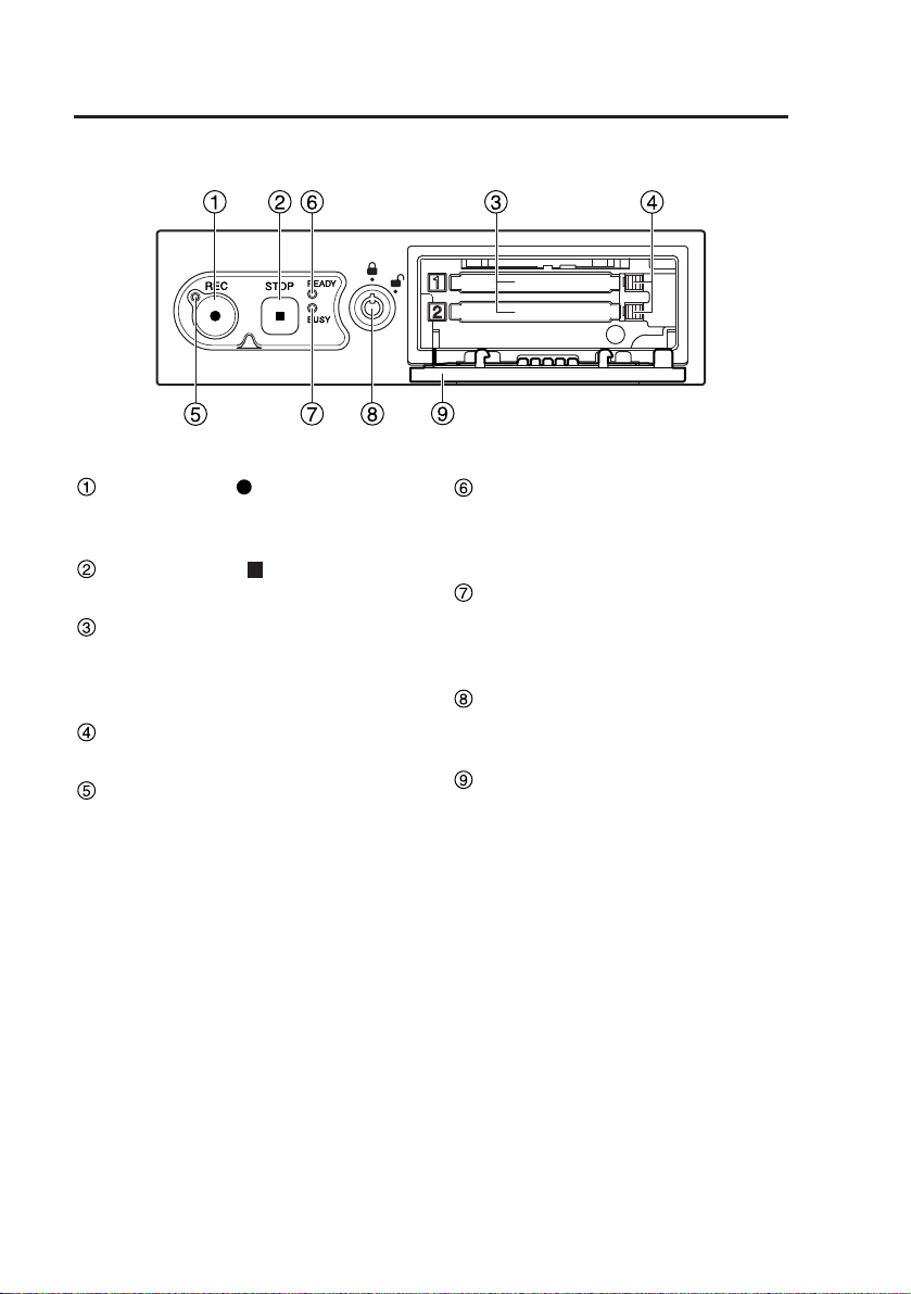
Control reference guide
Recorder front panel
REC button ( )
Starts recording of video and sound
to a P2 card.
STOP button ( )
Stops recording.
P2 card slots 1, 2
Insert P2 cards here. Up to two
cards can be inserted
simultaneously.
EJECT button
Serves to eject a P2 card.
REC LED
Lights up during recording. If the
combined remaining recording time
for the cards inserted in the P2 card
slots 1 and 2 is less than 30
minutes (see page 20), the LED
starts to flash.
READY LED
Lights up when recording is
possible on a P2 card inserted in a
P2 card slot (see page 20).
BUSY LED
Lights up or flashes while a P2 card
is accessed (recording or playback;
see page 20).
Lock
Serves to lock and unlock the cover
of the P2 card slots.
Cover
Protects the P2 card slots.
Page 9
9
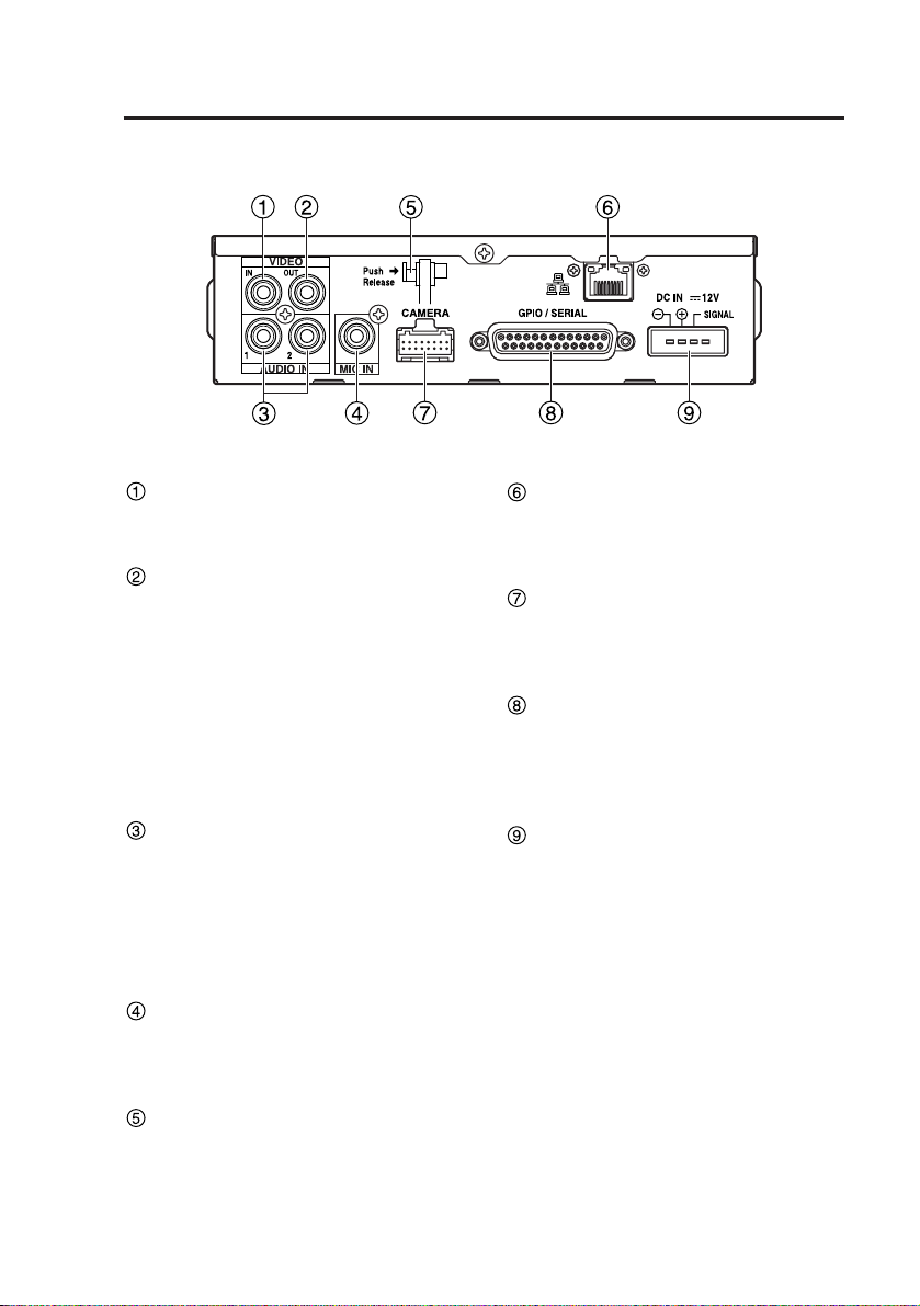
Control reference guide (continued)
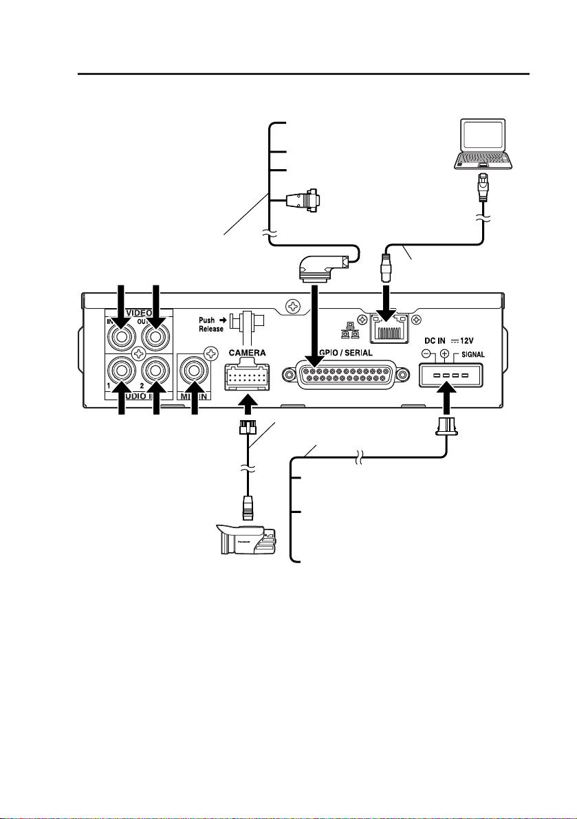
Recorder rear panel
VIDEO IN connector
(Pin jack)
This is a composite signal input.
VIDEO OUT connector
(Pin jack)
This is a composite signal output.
The signal from the camera cable
connector or the VIDEO IN
connector can be supplied here. For
information on how to select the
signal, see the documentation of the
Toughbook-Arbitrator Front End
Software.
AUDIO IN 1, 2 connectors
(Pin jack)
These are line level signal inputs.
The output signals of audio
components can be connected
here. For details on the connection,
see the installation manual.
MIC IN connector (Pin jack)
This is a microphone level signal
input. For details on the connection,
see the installation manual.
Cable clamp
This clamp can be used to fasten
the video cable, audio cable,
camera cable, and power cable.
LAN port
This port allows a 100BASE-TX
connection to a computer. Use the
supplied LAN cable.
Camera cable connector
Use the supplied camera cable to
connect the camera to the supplied
recorder.
GPIO/SERIAL connector
This connector serves as a
combined trigger signal input (8
lines), record tally output (1 line),
and serial port.
DC IN connector
This is the power supply connector.
Note:
Do not disconnect the power cable
while the recorder is operating. In
particular, if the power supply is
interrupted during recording, P2
card managing information and data
setting information may be lost or
damaged.
Page 10
10
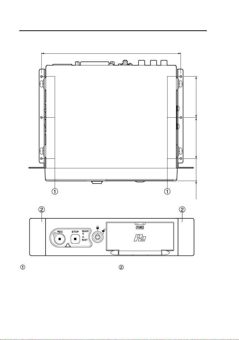
Control reference guide (continued)
Recorder mount adapter
55
55
187.4
(7-3/8 ")
(2-5/32 ")
(2-5/32 ")
30
(1-5/32 ")
Trunk mounting holes
These holes are used to mount the
recorder in the trunk.
For details, see the installation
manual.
Spaces for center console
mounting holes
In these spaces the holes can be
made to mount the recorder on the
center console.
For details, see the installation
manual.
Page 11
11
Control reference guide (continued)
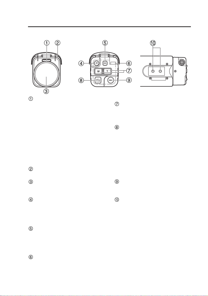
Camera front, rear, and top
REC LED
Lights up during recording.
The LED starts to flash when the
combined remaining recording time
for the cards inserted in the P2 card
slots 1 and 2 is less than 30
minutes (see page 20). The LED
can also be permanently turned off
using a Toughbook-Arbitrator Front
End Software setting. For details on
the setting procedure, see the
documentation of the ToughbookArbitrator Front End Software.
Sun shade
Protects the lens from direct sunlight.
Wide conversion lens
The wide conversion lens enables a wider
viewing angle when recording video.
Backlight compensation
button
Controls the backlight compensation
function. Each push of the button
switches the function ON or OFF.
Light button
Controls the camera operation
panel illumination. Each push of the
button switches the illumination ON
or OFF.
Camera cable connector
Use the supplied camera cable to
connect the camera to the supplied
recorder.
Zoom buttons
Control the zoom function. The W
button serves to zoom out and the
T button to zoom in.
Auto zoom button
Pressing this button causes the
camera to automatically zoom in,
pause for a certain period, and
zoom out. The zoom factor and
pause duration can be set. For
details on the setting procedure,
see the documentation of the
Toughbook-Arbitrator Front End
Software.
REC button
Pressing this button causes the
recorder to start recording.
Camera mount holes
The supplied camera mount can be
attached here.
When the wide conversion lens is
mounted, use the front hole (A).
When the wide conversion lens is
removed, use the rear hole (B).
Notes:
•Use only the wide conversion lens
that was mounted on the camera
when delivered.
•Use only the specified camera
mount positions to install the
camera.
A
B
Page 12

12
Connections
• Turn power to all components off and disconnect the power cables before making
any connections. Be sure to finish all other connections first, and then connect
the power cables last. Also refer to the connector signal diagram on page 29 and
to the documentation of the components that are to be connected.
•
Verify that recording is not in progress prior to disconnecting any cables from the recorder.
Be sure to disconnect the power cable first, and then disconnect any other cables.
• A wrong power cable connection will lead to malfunction. Make sure that the
power cable is connected correctly.
• To reduce the risk of fire or shock hazard, installation and wiring must only be
performed by a professional installer.
• To reduce the risk of fire, the red (BATT) and white (SIGNAL) wires of the
power cable must be connected via fuses (5 A – 20 A) having UL Listing.
• The provided power cable is not for use in the engine compartment.
Page 13
13
Video
Input Output
(line level) (mic level)
Audio input
Camera
(supplied)
Camera cable (supplied)
LAN cable (supplied)
External trigger
cable (supplied)
Power cable (supplied)
Computer
(available separately)
Others: Input signal lines
White (SIGNAL): Connect the signal line via
timer equipment and a fuse
Black (GND): Connect to the negative
terminal of the battery
Red (BATT):
Connect via a fuse to a power supply
that is constantly on, regardless of
ignition key ON/OFF status
White: Rec Tally output line
RS-232C: Connect to equipment
with serial connectors
Black: Connect to the negative
terminal of the battery
Connections (continued)
Page 14
14
P2 card insertion and removal
Never open the cover or remove the P2 card while the P2 card is being
accessed. Otherwise the data on the card may be lost or damaged, and the P2
card slot may become inoperative.
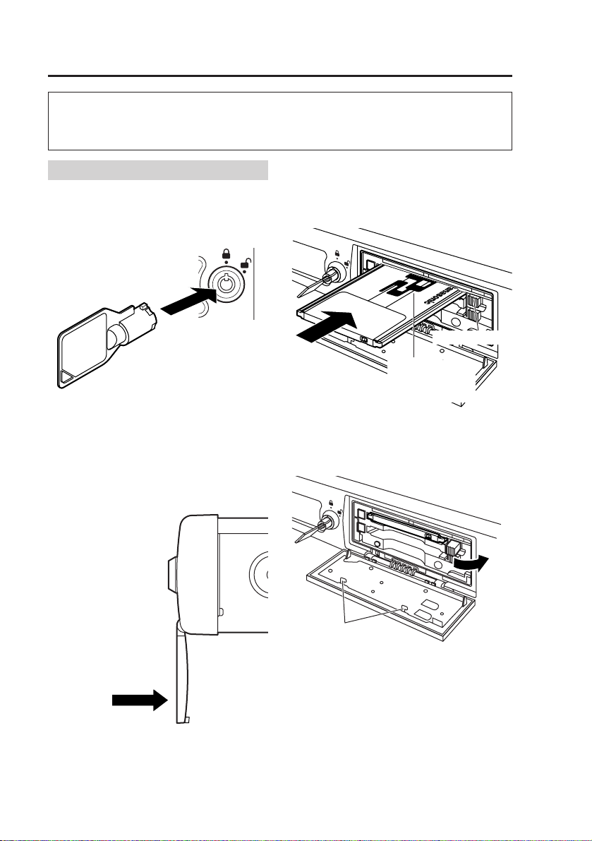
Inserting a P2 card
(1) Open the cover.
Insert the key into the lock and
turn it clockwise by 60 degrees.
(2) Insert a P2 card into the P2
card slot and push it in until
the EJECT button pops out.
Do not push in this
direction.
EJECT button
Insert the card
with the P2 logo
facing up.
Do not touch to avoid
the risk of injury.
Notes:
•To prevent damage, do not exert
undue force on the open cover.
•Do not try to turn the key further
than the stop position, and do not
move it unnecessarily, to prevent
damage to the key and lock.
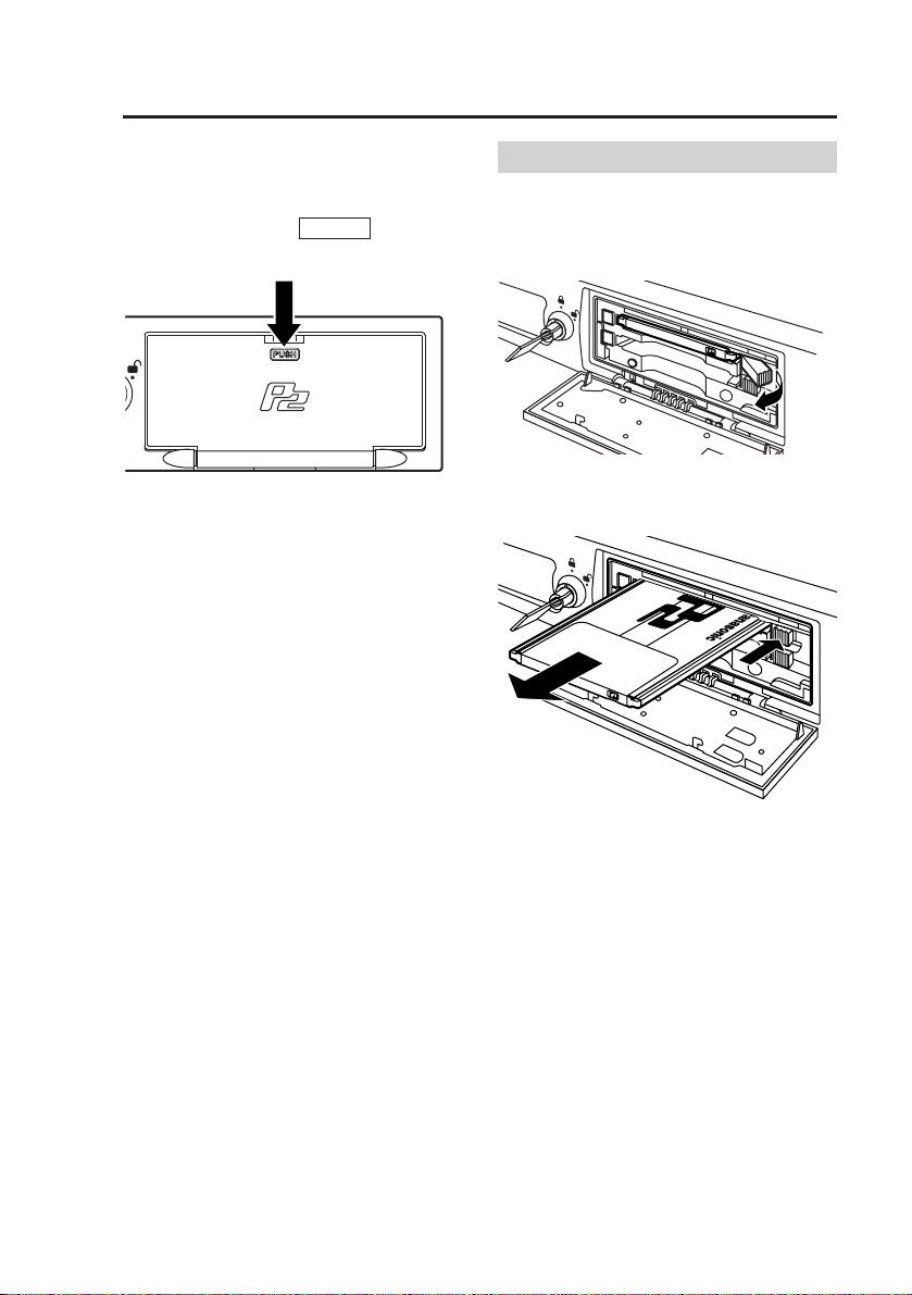
(3) Fold the protruding EJECT
button to the right.
Note:
Make sure that the EJECT button
has been properly positioned as
illustrated above before closing the
cover. Otherwise the EJECT button
will be damaged.
Page 15
15
P2 card insertion and removal (continued)
Note:
If a P2 card was removed while
data was being accessed, files may
be corrupted. In some rare cases,
the P2 card slot may become
inoperative. If this case, the files
must be restored by controlling the
recorder from the ToughbookArbitrator Front End Software.
When this is detected, the recorder
automatically restarts itself.
(4) Close the cover.
Return the cover to its original
closed position and press the
section marked .
PUSH
When you close the cover after
inserting a P2 card, the READY LED
indicates the recorder status (see page
20).
(5) Turn the key counterclockwise to
lock the cover and to allow
removal of the key from the lock.
Removing a P2 card
(2) Raise the EJECT button.
(1) Open the cover
(see previous page).
(3) Push the EJECT button so
that the P2 card pops out.
(4) Close the cover
(see top left of this page).
(5)
Turn the key counterclockwise
to lock the cover and to allow
removal of the key from the lock.
Page 16

16
Recording and stopping
Recording
Recording can be started by one of the
following methods:
•
Pressing the REC button on the recorder.
•
Pressing the REC button on the camera.
•Clicking the REC button in the
Toughbook-Arbitrator Front End
Software.
• Activating a recording start trigger
from a device connected via the
GPIO/SERIAL connector on the
recorder. (A setting must first be
made with the ToughbookArbitrator Front End Software.)
•
Setting the SIGNAL pin of the power
cable connected to the DC IN connector
of the recorder to ON. (A setting must
first be made with the ToughbookArbitrator Front End Software.)
When recording starts, the prerecording
function operates to ensure that material
from a certain interval before the start
point is included in the recording. (For
details on prerecording, see page 17.)
The duration of this interval can be set
with the Toughbook-Arbitrator Front End
Software. For details, see the
documentation of the ToughbookArbitrator Front End Software.
Make sure that the camera cable,
external trigger cable, and audio cables
(available separately) as well as any
other cables are connected correctly, as
described in the installation manual.
Notes:
•Recording can be started only if
the READY LED on the recorder is
lit. If recording is not possible when
the REC button is pressed or the
recording start trigger signal is
activated, the REC LED on the
recorder and the camera will flash
for about 1 second.
•The video signal from the input
selected with the ToughbookArbitrator Front End Software will
be recorded (see page 18).
Recording can be stopped by one of
the following methods:
•Pressing the STOP button on the
recorder.
•
Clicking the STOP button in the ToughbookArbitrator Front End Software.
When recording is stopped, the postrecording function operates to ensure
that material from a certain interval
after the stop point is included in the
recording. The duration of this interval
can be set with the ToughbookArbitrator Front End Software.
Notes:
•The entire video and audio content
of the recording period, including
the prerecording and postrecording intervals, is stored as
one file on the P2 card.
•When recording on a 4 GB P2 card
at 512 kbps recording rate, the
recording time may be 17 hours or
more, if there is no great change in
the recorded image. In such a
case, the recorded file will be
automatically split.
•
When recording is started by a
recording start trigger signal, the
recorded video signal will always be
the signal originating from the
camera unit, via the camera input
cable. If a recording start trigger
signal is activated while recording a
video signal from the VIDEO IN
connector, recording will
automatically switch to the video
signal originating from the camera
unit, via the camera input cable.
•The audio signal from the input
selected with the ToughbookArbitrator Front End Software will
be recorded (see page 18).
•If the cover is opened during
recording, recording will stop.
•If the cover is not closed, recording
cannot be restarted.
Stopping
Page 17

17
Recording and stopping (continued)
Write-protect switch
The P2 card is equipped with a writeprotect switch. If you set this switch to
the PROTECT position, no data can
be written to the P2 card and no
existing file can be deleted.
PROTECT
write-protect switch
Prerecording and post-recording
Prerecording is the capability of including
material from an interval before the
specified start point in a recording.
Similarly, post-recording is the capability of
including material from an interval after the
specified stop point in a recording. The
intervals (prerecord time and post-record
time) can be set using the ToughbookArbitrator Front End Software.
If recording is started
immediately after system startup
Prerecord time will be shorter.
If recording is started during
post-record interval
Post-recording will be terminated
and next recording starts. There is
no prerecording interval for the
second recording.
REC button pressed
(Recording starts)
STOP button pressed
(Recording stops)
Actual recording time
Prerecord time Post-record time
Prerecord time Post-record time
REC button pressed
(Post-recording halted and
next recording starts)
STOP button
pressed
(Recording stops)
STOP
button
pressed
Actual recording time
REC button pressed
(Recording starts)
STOP button pressed
(Recording stops)
Startup
completed
Post-record time Post-record time
In the cases shown below, the actual
prerecord and post-record time may be
shorter than the respective setting.
Notes:
•
If you press the REC button and
STOP button alternately in rapid
succession, the system may not
separate the two recording sessions,
resulting in a single video file.
•
If the remaining capacity of the P2
card is low, the prerecord time or postrecord time may become shorter.
Notes:
•Any attempt to change the position
of the write-protect switch during
power-on will have no effect. To
produce the effect, turn the power
off and then turn it on again or
remove the card and then insert it
again.
•If the write-protect switch is set to
the PROTECT position on any of
the cards in the two card slots,
recording will not start.
Actual recording time
Time
Time
Time
Page 18

18
Recording and stopping (continued)
Selecting the video source to record
You can select to record from either
the camera cable input signal or the
VIDEO IN connector input signal on
the rear panel. This selection is made
using the Toughbook-Arbitrator Front
End Software.
If a recording start trigger signal is
activated while recording a signal from
the VIDEO IN connector, recording of
the VIDEO IN signal will stop and
recording of the camera cable input
signal will begin. In this case, separate
files will be created. When recording is
started by trigger activation, there will
be no prerecording or post-recording.
Recording start trigger activation
Recording of signal
from VIDEO IN
connector
Recording of signal from
camera cable connector
Notes:
•If switching was performed by
supplying a recording start trigger,
the input signal immediately after
switching will not be recorded.
•
If the video signal selection is
changed during post-recording, postrecording will be halted
.
•If recording is started immediately
after selecting the video signal, the
prerecord time may be shorter
than the setting.
•When the recorder is restarted, the
default video signal input setting is
always the camera cable
connector, regardless of which
selection was active before
shutdown.
Note:
When the recorder is restarted, the
default audio signal setting is
always the MIC, regardless of which
selection was active before
shutdown.
Time
The recorder can record up to two
audio channels (L-CH and R-CH). Out
of the three audio input connectors on
the rear panel (AUDIO IN 1, 2, and
MIC IN), the signal of the source
connected to the AUDIO IN 1
connector will always be recorded on
the left channel (L-CH). For the right
channel (R-CH), you can select either
the signal from the AUDIO IN 2
connector or the MIC IN connector.
This selection is made using the
Toughbook-Arbitrator Front End
Software.
The following two audio recording
modes are available: AUDIO IN 2 and
MIC
AUDIO IN2
During recording, the audio signal
from the AUDIO IN 2 connector will
always be recorded on the right
channel (R-CH).
MIC
During recording, the audio signal
from the MIC IN connector will
always be recorded on the right
channel (R-CH).
Audio sources when recording
Page 19

19
Zoom function
The camera has the capability for
optical zoom (x22) and digital zoom
(x10). The zoom function is controlled
with the W button and the T button.
The maximum zoom factor is x220.
When zooming in on a subject from
the wide end, zooming automatically
pauses at the x22 limit of the optical
zoom. To zoom beyond this limit with
the digital zoom, release the zoom
button momentarily and press it
again, holding it down until the
desired zoom factor is reached. The
same process is used to zoom out
from the telephoto end.
Auto zoom function
When you press the auto zoom
button, the camera will
automatically zoom in, pause for a
certain period, and zoom out. The
zoom factor and pause duration can
be set with the ToughbookArbitrator Front End Software.
Camera operation
Backlight compensation function
When you press the backlight
compensation button, the backlight
compensation function is activated.
Each push of the button toggles the
function between ON and OFF.
Light button
Pressing this button activates the
camera operation panel illumination.
Each push of the button toggles the
illumination between ON and OFF.
Page 20

20
LEDs and recorder status
The relationship between the on/flashing status of the indicator LEDs on the recorder
and camera and the operation status of the recorder is shown in the table below.
: LED lit : LED flashing : LED out
1
“REC LED” refers to the following indicators and pins:
•REC LED on recorder
•REC LED on camera
•GPIO9 (pin 25) output of GPIO/SERIAL port (Rec Tally)
The REC LED on the camera and the GPIO9 output connector will not flash
immediately after power-on.
2
Shows the following P2 card status information:
• No P2 card is inserted.
• P2 card does not have sufficient free space.
• Write-protect switch is set to the PROTECT position on at least one card.
3
Carried out by the recorder in response to a request by the Toughbook
Arbitrator Front End Software.
4
If the P2 card does not have sufficient free space, the READY LED does not light.
5
Recorder administrator settings can be changed from the Toughbook-Arbitrator
Front End Software.
• If recording is already in progress or if recording cannot be started when the
REC button is pressed or a recording start trigger is activated via the
GPIO/SERIAL port, the REC LED flashes for about 1 second.
• During card access immediately after the cover was opened or closed, the
BUSY LED flashes.
LED status
REC1READY BUSY
Immediately after power-on
During startup
Standby (recording possible)
Standby (recording impossible)
2
Recording in progress
Recording in progress (remaining capacity less than. 30 minutes)
Post-recording in progress
File restoration in progress
3
Playback (upload) in progress
4
Setting change in progress
5
Cover is open
Shutdown in progress
Recorder status
Page 21

21
Notes on handling
Installation
• Install the recorder and camera
properly as described in the
installation manual, so that the
units cannot come loose or fall off.
• Do not place heavy objects on the
power cable and other connection
cables.
• Do not exceed the rating of any
connection cables and other wiring
parts.
• Use only the supplied accessories
and specified optional accessories.
• Keep the recorder, camera, P2
card, power cable and connection
cables away from heat sources.
• Protect the recorder, camera and
P2 cards from oily smoke,
humidity, moisture, and dust.
• Do not touch the power supply
connector with wet hands.
• Do not block the ventilation holes
of the recorder.
Usage
• The recorder is designed to be
powered from a 12-volt source. It
cannot be used in vehicles with a
different electrical source voltage.
(Never connect the recorder to a
24-volt source.)
• When using the recorder for the
first time or after reconnecting it to
the power supply, be sure to set
the date, time, and time zone of
the internal clock using the
Toughbook-Arbitrator Front End
Software.
• Do not place any container with
liquid or any small metal objects
on top of the recorder, camera, or
P2 card.
• Do not insert any foreign objects
into the openings of the unit.
• Do not attempt to modify the
recorder, camera, or P2 card.
• Take care not to damage the
power cable or connection cables.
Do not modify, bend, twist, curl, or
pull these parts or subject them to
a strong stress force. Also avoid
exposure to high temperatures.
• Protect the recorder, camera, and
P2 cards from moisture and do not
expose them to water.
• Do not place heavy objects on the
recorder or camera and do not
step on these parts. Do not
suspend any heavy objects from
the mounted camera.
• Before moving the recorder or
camera, be sure to disconnect the
power cable and other connection
cables.
• Do not handle the recorder or
camera while driving a vehicle.
• Only P2 type memory cards can
be used in the recorder. Do not
use any other type of card,
because this will damage the
recorder.
• When inserting a P2 card, proceed
carefully and do not use excessive
force. Otherwise the P2 card or
the card slot will be damaged.
• Do not insert the P2 card upside
down.
• Do not insert a damaged or
deformed P2 card.
Page 22

22
• Do not disconnect the power cable
while the recorder is operating. Be
sure to perform recorder shutdown
before disconnecting the cable.
Otherwise recorder setting files
and P2 card managing information
may be lost or damaged.
When the SIGNAL pin at the DC
IN connector goes OFF, the
recorder will perform shutdown
after an interval set with the
Toughbook-Arbitrator Front End
Software.
• Do not open the cover during P2
card access (BUSY LED is lit or
flashing). Do not exert undue force
on the cover to prevent damage.
• Never remove the P2 card from
the card slot during P2 card
access (BUSY LED is lit or
flashing). Otherwise data on the
P2 card will be destroyed.
• Take care not to pinch your fingers
in the P2 card slots or the cover.
• Protect the connector section of
the P2 card from dust, sand,
moisture etc. If a card has been
exposed to any of these, do not
insert it in the P2 card slot.
• Take care that no dust, sand,
moisture etc. can enter a P2 card
slot.
• Before closing the cover, make
sure that the EJECT button is
folded to the right.
• Do not exert undue force on the
EJECT button to prevent damage.
What to do in case of a problem
• If the recorder or camera was
dropped, or if a foreign substance
has entered a unit, stop recording,
shut down the unit and disconnect
the power cable.
• If a component emits smoke,
unusual smell or noise, or if
another problem occurs,
disconnect the power cable.
Maintenance
• Before performing any
maintenance operation, make sure
that the recorder is not operating
and then disconnect the power
cable.
• Regularly check the ventilation
holes for blockage by dust etc.
Notes on handling (continued)
Page 23

23
Factory default settings
The factory default settings are listed in the table below. To change any of these
settings, use the Toughbook-Arbitrator Front End Software, but “17 IP Address”
will not be changed.
Item Value Description
(Recorder related settings)
Shift
Shift Start 2005-01-01 Shift start date, time and day
1
09:00
SAT
Shift End 2005-01-01 Shift end date, time and day
1
17:00
SAT
Shift Pattern ---- Shift pattern
Officer
Officer1 first name
---- Officer 1 first name
Officer1 mid name
- Officer 1 middle name
Officer1 last name
---- Officer 1 last name
Officer1 ID -------- Officer 1 ID
Officer2 first name
---- Officer 2 first name
Officer2 mid name
- Officer 2 middle name
Officer2 last name
---- Officer 2 last name
Officer2 ID -------- Officer 2 ID
3 Vehicle ID -------- Patrol car ID
4 Area ---- Area number
5 Record Rate 512 K Recording bit rate
Setting values 1M: 1 Mbps
512 K: 512 Kbps
6 Time and Date (undefined) Year Month/Day Hour/Minutes Seconds
7 Time Zone
Pacific Daylight
Time zone
Saving Time
Setting values:
Hawaii Standard Time
Yukon Standard (Daylight Saving) Time
Pacific Standard (Daylight Saving) Time
Mountain Standard (Daylight Saving) Time
Central Standard (Daylight Saving) Time
Eastern Standard (Daylight Saving) Time
Atlantic Standard (Daylight Saving) Time
Asia Tokyo
1
2
1
Displayed values differ depending on the Time Zone setting.
Page 24

24
Factory default settings (continued)
8 V-CH 1 Video input
Setting values1: Camera cable connector input
2: VIDEO IN connector input
9 AUDIO2 MIC Audio input
Setting values: AUDIO IN2
MIC
(For information on audio settings, see page 18.)
10 Pre Time 120 Prerecord time (seconds)
Setting values: 0 - 180
11 Post Time 120 Post-record time (seconds)
Setting values: 0 - 180
12 Power On/Off 120 Time lag between SIGNAL off and
recorder shutdown (minutes)
Setting values: 0 - 180
1
13 P-Rec OFF
Automatically start recording at SIGNAL ON
Setting values: ON
OFF
GPIO
Settings for GPIO ports 1 - 8 (common to all ports)
GPIO On/Off ON Enable/disable global GPIO
Setting values:
ON (Globally enable GPIO input)
OFF (Globally disable GPIO input)
DETECTION H
Individual trigger settings for GPIO 1 - 8
Setting values: N (No input)
H (High-edge trigger)
L (Low-edge trigger)
B (Both-edge trigger)
Name ---- GPIO 1 - 8 names
Setup ON
Individual OSD display settings for GPIO 1 - 8
Setting values: ON (OSD on)
OFF (OSD off)
Printable - OSD character string for GPIO 1 - 8
15 AUDIO2 REC ON Audio R-CH recording
Setting values: ON
OFF
14
1
When set to “0”, the recorder will perform shutdown after about one minute.
Page 25

25
Factory default settings (continued)
OSD
OSD On/Off OSD On OSD enable/disable
GPIO On
Setting values: OSD OFF
TimeDate On
OSD ON, GPIO ON, TimeDate ON
OSD ON, GPIO ON, TimeDate OFF
OSD ON, GPIO OFF, TimeDate ON
TIME-DATE ISO Time/Date display format
STYLE Setting values: ISO (ISO format)
USA (USA format)
--- 1lineUpper Display position
Setting values:
1lineUpperEnd:1-line display, upper end
1lineUpper
:
1-line display, top
1lineBottom
:
1-line display, bottom
1lineBottomEnd
:
1-line display, bottom end
2linesL-upper
:
2-line display, upper left
2linesR-upper
:
2-line display, upper right
2linesL-bottom
:
2-line display, bottom left
2linesR-bottom
:
2-line display, bottom right
3linesL-upper
:
3-line display, upper left
3linesR-upper
:
3-line display, upper right
3linesL-bottom
:
3-line display, bottom left
3linesR-bottom
:
3-line display, bottom right
16
Page 26

26
Factory default settings (continued)
R-Protocol
Baud Rate 4800 Radar gun communication rate (bps)
Setting value: 50 - 230400
Bit Length 8 Communication word length (bits)
Setting values: 8
7
Stop Bit 1 Stop bits (bit)
Setting value: 1,2
Parity NON Parity
Setting values: ODD
NON
EVEN
Delimit OFF Delimiter
Character
Setting value: OFF
\D
\ A
Buffer Size 255 Transfer buffer size (bytes)
Setting value: 0 - 256
Data timeout 1 Transfer timeout (100 msec.)
Setting value: 1 - 999
IP Address
192.168.10.10/24
IP Address of the recorder
(This will not be changed.)
17
18
Page 27

27
Factory default settings (continued)
(Camera related settings)
1 ZOOM-LIM 22 Maximum zoom factor
Target Magnification
Setting values: 22 - 220
(The values except 22 are multiples of 20.)
1 - 220
(Values from 1 to 22 are integers, and values
of 40 and above are multiples of 20.)
2 AUTO ZOOM 10
Target zoom factor when AutoZoom command is received
Target Magnification
Setting values: 1 - 22 (integers)
3 AUTO ZOOM 3
Interval of maintaining target zoom
Maintenance Time
factor when AutoZoom command is received
Setting values: 0 - 9 (integers)
4 Back Light OFF Backlight compensation enable/disable
Setting values:
ON (Backlight compensation enabled)
OFF (Backlight compensation disabled)
5 Camera LED ON
Camera REC LED enable/disable
Setting values:
ON (Camera REC LED lights up during recording)
OFF (Camera REC LED is always off)
6 Flip OFF
Camera output image top/bottom flip enable/disable
Setting values:
ON (Top/bottom flip enabled)
OFF (Top/bottom flip disabled)
Page 28

28
Factory default settings (continued)
7 Infra Red AUTO
IR function auto switch/always ON/always OFF
2
Setting values:
AUTO (IR function is automatically switched on and off)
ON (IR function is always on)
OFF (IR function is always off)
8 IR-Level LOW
Level setting for IR auto switching mode
2
Setting values: LOW
HIGH
9 IR-Time 30 Detection time setting for IR auto
switching mode (seconds)
2
Setting values: 10: 10 seconds
30: 30 seconds
60: 60 seconds
300: 300 seconds
10 AGC HIGH Camera input gain setting
Setting values: LOW
MID
HIGH
OFF
11 AE Shift 0 Auto exposure shift
3
Setting values: –2, –1, 0, 1, 2
2
The IR-Level and IR-Time settings are only available when IR is set to AUTO.
3
When the “AE Shift” value is “2” and the object is fairly dark, the image may not
be updated at the 30 frames per second rate.
The default AE shift value is always 0, when the recorder is restarted.
Page 29

29
Connector signals
1 N.C.
2 V_OUT
3 BL_L
4 AUTO_ZOOM_L
5 REC_L
6 GND (DC_IN)
7 DC_IN
8 N.C.
9 GND (SHIELD)
10 GND (V_OUT)
11 GND (TxD/RxD)
12 TxD
13 RxD
14 REC_LED_L
15 GND (SHIELD)
16 GND (SHIELD)
Camera cable connector
(recorder/female)
1 GND Black
2 BATT Red
3 SIGNAL White
4 N.C.
DC IN connector
(recorder/female)
Pin
number
Signal
Pin
number
Signal Cable color
1
916
8
1
4
Power cable (supplied)
Red
Black
White
The SIGNAL pin can be used to turn power to the recorder on and off. When an
OFF signal is input at this pin while the recorder is powered, the recorder will
turn off after an interval set with the Toughbook-Arbitrator Front End Software.
Page 30

30
Connector signals (continued)
1 N.C.
2 TxD Serial
3 RxD Serial
4 RTS Serial
5 CTS Serial
6 DSR Serial
7 SG Serial
8 CD Serial
9 GND GPIO Black
10 GPIO1 In Brown
11 GPIO2 In Red
12 GPIO3 In Orange
13 GPIO4 In Yellow
14 N.C.
15 N.C.
16 N.C.
17 N.C.
18 N.C.
19 N.C.
20 DTR Serial
21 GPIO5 In Green
22 GPIO6 In Blue
23 GPIO7 In Purple
24 GPIO8 In Gray
25 GPIO9 Out White
GPIO/Serial connector
(recorder/female)
Pin
number
Signal Remarks
Cable
color
25 14
1
External
trigger cable
(supplied)
Brown
Red
Orange
Yellow
Green
Blue
Purple
Gray
White
Black
RS-232C
Page 31

31
Connector signals (continued)
Camera cable connector
(camera/female)
1 GND (SHIELD)
2 REC_LED_L
3 RxD
4 TxD
5 GND (TxD/RxD)
6 GND (V_OUT)
7 DC_IN
8 GND (DC_IN)
9 REC_L
10 AUTO_ZOOM_L
11 BL_L
12 V_OUT
Pin
number
Signal
9
12
5
10
1
11
Page 32

32
Troubleshooting
Before requesting service, check the points listed below. If the problem persists,
contact your local Panasonic dealer.
Starting up
• Check whether power cable is connected
correctly.
• Check whether a timer device is inserted in the
power supply for the recorder. Refer to the
installation manual and connect the timer
equipment correctly.
• Check the time lag setting between SIGNAL off
and recorder power-off. For details, see the
documentation of the Toughbook-Arbitrator
Front End Software.
Operation
• Are you using the supplied key?
• Is the cover closed? The key can only be
removed if the cover is closed.
• Is a P2 card inserted correctly in a P2 card slot?
• Is the EJECT button folded to the right?
• Is the supplied LAN cable (crossing type) being
used? Connect the recorder and the computer
on which the Toughbook-Arbitrator Front End
Software is running directly, not via a hub.
• Are the network settings on the computer
correct? Subnet mask of the recorder and that
of the computer must be the same. For details,
see the documentation of the ToughbookArbitrator Front End Software.
• When you press and hold the REC button and
STOP button on the recorder simultaneously for
about 10 seconds, the recorder will restart.
Reset the computer after this.
•
To reset the unit, hold down the REC button and STOP
button on the front panel together for about 10 seconds.
All LEDs go out for 1 - 2 seconds and then light
up for 1 - 2 seconds. Reset is now possible.
• If you remove the P2 card during P2 card
access (BUSY LED is lit), the P2 card slot may
become inoperative. In such a case, the
recorder automatically restarts itself, and the
card slot will become operative again.
Recorder
Cover cannot be opened.
Power does not come on.
Power gets turned off
automatically.
Key cannot be removed
from lock.
Control from ToughbookArbitrator Front End
Software is not possible.
The unit does not respond
or another problem has
occurred.
Recorder was restarted
without performing a
reset.
Cover cannot be closed.
Page 33

33
Recorded data have
become totally or partially
unusable.
Troubleshooting (continued)
Recording
(Check this with the Toughbook-Arbitrator Front
End Software.)
• Is a P2 card inserted?
• Does the P2 card have sufficient free space?
Check the free space with the ToughbookArbitrator Front End Software. Upload files and
free up space.
• Make sure that the write-protect switch of the P2
card is not set to PROTECT.
• Is the GPIO cable connected properly? Also
connect the ground line of the GPIO cable. For
details, see the installation manual.
• Are the settings for the GPIO/SERIAL port
correct? For details, see the documentation of
the Toughbook-Arbitrator Front End Software.
• Is the P2 card usable? If file information cannot
be obtained using the Toughbook-Arbitrator
Front End Software, you should format the P2
card. For information on formatting, see the
installation manual. (When you format a P2
card, all existing data on it will be erased.)
• If the power source was interrupted or if the
power cable was disconnected during recording,
data may become corrupted. Ensure that power
is never interrupted during recording. In some
cases, it may be possible to restore corrupted
data using the Toughbook-Arbitrator Front End
Software.
Cannot start recording.
Page 34

34
Troubleshooting (continued)
(Check this with the Toughbook-Arbitrator Front
End Software.)
• Are camera and video monitoring equipment
connected properly?
• Are both the video input connector selection and
the input selection made with the ToughbookArbitrator Front End Software the same?
• Are the video output settings correct for the
connected equipment? Connect a monitor to the
VIDEO OUT connector on the rear panel of the
recorder and check the picture.
(Check this with the Toughbook-Arbitrator Front
End Software.)
• Is the cable connection to the audio input
correct?
• Are both the audio input connector selection
and the input selection made with the
Toughbook-Arbitrator Front End Software the
same?
• Are the audio output settings correct for the
connected equipment? Consult the
documentation of the connected equipment to
check this.
• Check the audio settings at the computer.
(Check this with the Toughbook-Arbitrator Front
End Software.)
• Are the communication settings of the
connected equipment and the settings for the
SERIAL port of the recorder the same? Check
this while referring to the documentation for
connected equipment and the ToughbookArbitrator Front End Software.
Video is distorted or not
recorded.
Sound is distorted or not
recorded.
Information from
equipment connected via
the GPIO/SERIAL port is
not recorded in the meta
data file
Page 35

35
Video is distorted or not
recorded.
Troubleshooting (continued)
Power does not come on.
Starting up and during operating
• Is the camera cable connected correctly? Check
this while referring to the installation manual.
• Immediately after power-on or when switching
to IR mode, a mechanical operation sound will
be heard. This is not a malfunction of the
camera.
• During zoom, some operation noise will be
heard. This is not a defect.
Picture
(Check this with the Toughbook-Arbitrator Front
End Software.)
• Are camera and video monitoring equipment
connected properly?
• Are both the video input connector selection and
the input selection made with the ToughbookArbitrator Front End Software the same?
• Are the video output settings correct for the
connected equipment? Connect a monitor to the
VIDEO OUT connector on the rear panel of the
recorder and check the picture.
• The IR function was enabled, which results in a
B/W picture.
• Under some circumstances, correct focus may
be difficult to achieve with auto-focusing. A few
examples are listed below:
· The field of view includes both distant and
near objects.
· The camera is shooting through dirty window
glass.
· Ambient lighting is low.
· There are bright and reflective surfaces
around the object.
· The camera is shooting a rapidly moving
object.
· The object has little contrast.
· A close-by object is being shot at high zoom
ratio.
Camera
Recorded video is in
black and white.
Automatic focusing does
not work.
Unusual sound is heard.
Page 36

36
GPL
GNU GENERAL PUBLIC LICENSE
Version 2, June 1991
Copyright (C) 1989, 1991 Free Software Foundation, Inc.
59 Temple Place, Suite 330, Boston, MA 02111-1307 USA
Everyone is permitted to copy and distribute verbatim
copies of this license document, but changing it is not
allowed.
Preamble
The licenses for most software are designed to take away
your freedom to share and change it. By contrast, the
GNU General Public License is intended to guarantee
your freedom to share and change free software--to make
sure the software is free for all its users. This General
Public License applies to most of the Free Software
Foundation’s software and to any other program whose
authors commit to using it. (Some other Free Software
Foundation software is covered by the GNU Library
General Public License instead.) You can apply it to your
programs, too.
When we speak of free software, we are referring to
freedom, not price. Our General Public Licenses are
designed to make sure that you have the freedom to
distribute copies of free software (and charge for this
service if you wish), that you receive source code or can
get it if you want it, that you can change the software or
use pieces of it in new free programs; and that you know
you can do these things.
To protect your rights, we need to make restrictions that
forbid anyone to deny you these rights or to ask you to
surrender the rights. These restrictions translate to certain
responsibilities for you if you distribute copies of the
software, or if you modify it.
For example, if you distribute copies of such a program,
whether gratis or for a fee, you must give the recipients all
the rights that you have. You must make sure that they,
too, receive or can get the source code. And you must
show them these terms so they know their rights.
We protect your rights with two steps: (1) copyright the
software, and (2) offer you this license which gives you
legal permission to copy, distribute and/or modify the
software.
Also, for each author's protection and ours, we want to
make certain that everyone understands that there is no
warranty for this free software. If the software is modified
by someone else and passed on, we want its recipients to
know that what they have is not the original, so that any
problems introduced by others will not reflect on the
original authors’ reputations.
Finally, any free program is threatened constantly by
software patents. We wish to avoid the danger that
redistributors of a free program will individually obtain
patent licenses, in effect making the program proprietary.
To prevent this, we have made it clear that any patent
must be licensed for everyone’s free use or not licensed at
all.
The precise terms and conditions for copying, distribution
and modification follow.
GNU GENERAL PUBLIC LICENSE
TERMS AND CONDITIONS FOR COPYING,
DISTRIBUTION AND MODIFICATION
0. This License applies to any program or other work
which contains a notice placed by the copyright holder
saying it may be distributed under the terms of this
General Public License. The “Program”, below, refers to
any such program or work, and a “work based on the
Program” means either the Program or any derivative
work under copyright law: that is to say, a work
containing the Program or a portion of it, either verbatim
or with modifications and/or translated into another
language. (Hereinafter, translation is included without
limitation in the term “modification”.) Each licensee is
addressed as “you”.
Activities other than copying, distribution and
modification are not covered by this License; they are
outside its scope. The act of running the Program is not
restricted, and the output from the Program is covered
only if its contents constitute a work based on the
Program (independent of having been made by running
the Program). Whether that is true depends on what the
Program does.
1. You may copy and distribute verbatim copies of the
Program’s source code as you receive it, in any
medium, provided that you conspicuously and
appropriately publish on each copy an appropriate
copyright notice and disclaimer of warranty; keep intact
all the notices that refer to this License and to the
absence of any warranty; and give any other recipients
of the Program a copy of this License along with the
Program.
You may charge a fee for the physical act of transferring
a copy, and you may at your option offer warranty
protection in exchange for a fee.
2. You may modify your copy or copies of the Program or
any portion of it, thus forming a work based on the
Program, and copy and distribute such modifications or
work under the terms of Section 1 above, provided that
you also meet all of these conditions:
a) You must cause the modified files to carry prominent
notices stating that you changed the files and the
date of any change.
b) You must cause any work that you distribute or
publish, that in whole or in part contains or is derived
from the Program or any part thereof, to be licensed
as a whole at no charge to all third parties under the
terms of this License.
c) If the modified program normally reads commands
interactively when run, you must cause it, when
started running for such interactive use in the most
ordinary way, to print or display an announcement
including an appropriate copyright notice and a
notice that there is no warranty (or else, saying that
you provide a warranty) and that users may
redistribute the program under these conditions, and
telling the user how to view a copy of this License.
(Exception: if the Program itself is interactive but
does not normally print such an announcement, your
work based on the Program is not required to print an
announcement.)
Page 37

37
GPL (continued)
These requirements apply to the modified work as a
whole. If identifiable sections of that work are not derived
from the Program, and can be reasonably considered
independent and separate works in themselves, then this
License, and its terms, do not apply to those sections
when you distribute them as separate works. But when
you distribute the same sections as part of a whole which
is a work based on the Program, the distribution of the
whole must be on the terms of this License, whose
permissions for other licensees extend to the entire whole,
and thus to each and every part regardless of who wrote
it.
Thus, it is not the intent of this section to claim rights or
contest your rights to work written entirely by you; rather,
the intent is to exercise the right to control the distribution
of derivative or collective works based on the Program.
In addition, mere aggregation of another work not based
on the Program with the Program (or with a work based on
the Program) on a volume of a storage or distribution
medium does not bring the other work under the scope of
this License.
3. You may copy and distribute the Program (or a work
based on it,under Section 2) in object code or
executable form under the terms of Sections 1 and 2
above provided that you also do one of the following:
a) Accompany it with the complete corresponding
machine-readable source code, which must be
distributed under the terms of Sections 1 and 2
above on a medium customarily used for software
interchange; or,
b) Accompany it with a written offer, valid for at least
three years, to give any third party, for a charge no
more than your cost of physically performing source
distribution, a complete machine-readable copy of
the corresponding source code, to be distributed
under the terms of Sections 1 and 2 above on a
medium customarily used for software interchange;
or,
c) Accompany it with the information you received as to
the offer to distribute corresponding source code.
(This alternative is allowed only for noncommercial
distribution and only if you received the program in
object code or executable form with such an offer, in
accord with Subsection b above.)
The source code for a work means the preferred form of
the work for making modifications to it. For an executable
work, complete source code means all the source code for
all modules it contains, plus any associated interface
definition files, plus the scripts used to control compilation
and installation of the executable. However, as a special
exception, the source code distributed need not include
anything that is normally distributed (in either source or
binary form) with the major components (compiler, kernel,
and so on) of the operating system on which the
executable runs, unless that component itself
accompanies the executable.
If distribution of executable or object code is made by
offering access to copy from a designated place, then
offering equivalent access to copy the source code from
the same place counts as distribution of the source code,
even though third parties are not compelled to copy the
source along with the object code.
4. You may not copy, modify, sublicense, or distribute the
Program except as expressly provided under this
License. Any attempt otherwise to copy, modify,
sublicense or distribute the Program is void, and will
automatically terminate your rights under this License.
However, parties who have received copies, or rights,
from you under this License will not have their licenses
terminated so long as such parties remain in full
compliance.
5. You are not required to accept this License, since you
have not signed it. However, nothing else grants you
permission to modify or distribute the Program or its
derivative works. These actions are prohibited by law if
you do not accept this License. Therefore, by modifying
or distributing the Program (or any work based on the
Program), you indicate your acceptance of this License
to do so, and all its terms and conditions for copying,
distributing or modifying the Program or works based on
it.
6. Each time you redistribute the Program (or any work
based on the Program), the recipient automatically
receives a license from the original licensor to copy,
distribute or modify the Program subject to these terms
and conditions. You may not impose any further
restrictions on the recipients’ exercise of the rights
granted herein. You are not responsible for enforcing
compliance by third parties to this License.
7. If, as a consequence of a court judgment or allegation
of patent infringement or for any other reason (not
limited to patent issues), conditions are imposed on you
(whether by court order, agreement or otherwise) that
contradict the conditions of this License, they do not
excuse you from the conditions of this License. If you
cannot distribute so as to satisfy simultaneously your
obligations under this License and any other pertinent
obligations, then as a consequence you may not
distribute the Program at all. For example, if a patent
license would not permit royalty-free redistribution of the
Program by all those who receive copies directly or
indirectly through you, then the only way you could
satisfy both it and this License would be to refrain
entirely from distribution of the Program.
If any portion of this section is held invalid or
unenforceable under any particular circumstance, the
balance of the section is intended to apply and the section
as a whole is intended to apply in other circumstances.
It is not the purpose of this section to induce you to
infringe any patents or other property right claims or to
contest validity of any such claims; this section has the
sole purpose of protecting the integrity of the free software
distribution system, which is implemented by public
license practices. Many people have made generous
contributions to the wide range of software distributed
through that system in reliance on consistent application of
that system; it is up to the author/donor to decide if he or
she is willing to distribute software through any other
system and a licensee cannot impose that choice.
This section is intended to make thoroughly clear what is
Page 38

38
GPL (continued)
believed to be a consequence of the rest of this License.
8. If the distribution and/or use of the Program is restricted
in certain countries either by patents or by copyrighted
interfaces, the original copyright holder who places the
Program under this License may add an explicit
geographical distribution limitation excluding those
countries, so that distribution is permitted only in or
among countries not thus excluded. In such case, this
License incorporates the limitation as if written in the
body of this License.
9. The Free Software Foundation may publish revised
and/or new versions of the General Public License from
time to time. Such new versions will be similar in spirit
to the present version, but may differ in detail to
address new problems or concerns.
Each version is given a distinguishing version number. If
the Program specifies a version number of this License
which applies to it and “any later version”, you have the
option of following the terms and conditions either of that
version or of any later version published by the Free
Software Foundation. If the Program does not specify a
version number of this License, you may choose any
version ever published by the Free Software Foundation.
10. If you wish to incorporate parts of the Program into
other free programs whose distribution conditions are
different, write to the author to ask for permission. For
software which is copyrighted by the Free Software
Foundation, write to the Free Software Foundation; we
sometimes make exceptions for this. Our decision will
be guided by the two goals of preserving the free status
of all derivatives of our free software and of promoting
the sharing and reuse of software generally.
NO WARRANTY
11. BECAUSE THE PROGRAM IS LICENSED FREE OF
CHARGE, THERE IS NO WARRANTY FOR THE
PROGRAM, TO THE EXTENT PERMITTED BY
APPLICABLE LAW. EXCEPT WHEN OTHERWISE
STATED IN WRITING THE COPYRIGHT HOLDERS
AND/OR OTHER PARTIES PROVIDE THE
PROGRAM “AS IS” WITHOUT WARRANTY OF ANY
KIND, EITHER EXPRESSED OR IMPLIED,
INCLUDING, BUT NOT LIMITED TO, THE IMPLIED
WARRANTIES OF MERCHANTABILITY AND
FITNESS FOR A PARTICULAR PURPOSE. THE
ENTIRE RISK AS TO THE QUALITY AND
PERFORMANCE OF THE PROGRAM IS WITH YOU.
SHOULD THE PROGRAM PROVE DEFECTIVE, YOU
ASSUME THE COST OF ALL NECESSARY
SERVICING, REPAIR OR CORRECTION.
12. IN NO EVENT UNLESS REQUIRED BY APPLICABLE
LAW OR AGREED TO IN WRITING WILL ANY
COPYRIGHT HOLDER, OR ANY OTHER PARTY
WHO MAY MODIFY AND/OR REDISTRIBUTE THE
PROGRAM AS PERMITTED ABOVE, BE LIABLE TO
YOU FOR DAMAGES, INCLUDING ANY GENERAL,
SPECIAL, INCIDENTAL OR CONSEQUENTIAL
DAMAGES ARISING OUT OF THE USE OR
INABILITY TO USE THE PROGRAM (INCLUDING
BUT NOT LIMITED TO LOSS OF DATA OR DATA
BEING RENDERED INACCURATE OR LOSSES
SUSTAINED BY YOU OR THIRD PARTIES OR A
FAILURE OF THE PROGRAM TO OPERATE WITH
ANY OTHER PROGRAMS), EVEN IF SUCH HOLDER
OR OTHER PARTY HAS BEEN ADVISED OF THE
POSSIBILITY OF SUCH DAMAGES.
END OF TERMS AND CONDITIONS
Page 39

39
LGPL
GNU LESSER GENERAL PUBLIC LICENSE
Version 2.1, February 1999
Copyright (C) 1991, 1999 Free Software Foundation, Inc.
59 Temple Place, Suite 330, Boston, MA 02111-1307
USA
Everyone is permitted to copy and distribute verbatim
copies of this license document, but changing it is not
allowed.
[This is the first released version of the Lesser GPL. It also
counts as the successor of the GNU Library Public
License, version 2, hence the version number 2.1.]
Preamble
The licenses for most software are designed to take away
your freedom to share and change it. By contrast, the
GNU General Public Licenses are intended to guarantee
your freedom to share and change free software--to make
sure the software is free for all its users.
This license, the Lesser General Public License, applies to
some specially designated software packages--typically
libraries--of the Free Software Foundation and other
authors who decide to use it. You can use it too, but we
suggest you first think carefully about whether this license
or the ordinary General Public License is the better
strategy to use in any particular case, based on the
explanations below.
When we speak of free software, we are referring to
freedom of use, not price. Our General Public Licenses
are designed to make sure that you have the freedom to
distribute copies of free software (and charge for this
service if you wish); that you receive source code or can
get it if you want it; that you can change the software and
use pieces of it in new free programs; and that you are
informed that you can do these things.
To protect your rights, we need to make restrictions that
forbid distributors to deny you these rights or to ask you to
surrender these rights. These restrictions translate to
certain responsibilities for you if you distribute copies of
the library or if you modify it.
For example, if you distribute copies of the library, whether
gratis or for a fee, you must give the recipients all the
rights that we gave you. You must make sure that they,
too, receive or can get the source code. If you link other
code with the library, you must provide complete object
files to the recipients, so that they can relink them with the
library after making changes to the library and recompiling
it. And you must show them these terms so they know
their rights.
We protect your rights with a two-step method: (1) we
copyright the library, and (2) we offer you this license,
which gives you legal permission to copy, distribute and/or
modify the library.
To protect each distributor, we want to make it very clear
that there is no warranty for the free library. Also, if the
library is modified by someone else and passed on, the
recipients should know that what they have is not the
original version, so that the original author’s reputation will
not be affected by problems that might be introduced by
others.
Finally, software patents pose a constant threat to the
existence of any free program. We wish to make sure that
a company cannot effectively restrict the users of a free
program by obtaining a restrictive license from a patent
holder. Therefore, we insist that any patent license
obtained for a version of the library must be consistent
with the full freedom of use specified in this license.
Most GNU software, including some libraries, is covered
by the ordinary GNU General Public License. This license,
the GNU Lesser General Public License, applies to certain
designated libraries, and is quite different from the
ordinary General Public License. We use this license for
certain libraries in order to permit linking those libraries
into non-free programs.
When a program is linked with a library, whether statically
or using a shared library, the combination of the two is
legally speaking a combined work, a derivative of the
original library. The ordinary General Public License
therefore permits such linking only if the entire
combination fits its criteria of freedom. The Lesser General
Public License permits more lax criteria for linking other
code with the library.
We call this license the “Lesser” General Public License
because it does Less to protect the user’s freedom than
the ordinary General Public License. It also provides other
free software developers Less of an advantage over
competing non-free programs. These disadvantages are
the reason we use the ordinary General Public License for
many libraries. However, the Lesser license provides
advantages in certain special circumstances.
For example, on rare occasions, there may be a special
need to encourage the widest possible use of a certain
library, so that it becomes a de-facto standard. To achieve
this, non-free programs must be allowed to use the library.
A more frequent case is that a free library does the same
job as widely used non-free libraries. In this case, there is
little to gain by limiting the free library to free software
only, so we use the Lesser General Public License.
In other cases, permission to use a particular library in
non-free programs enables a greater number of people to
use a large body of free software. For example,
permission to use the GNU C Library in non-free programs
enables many more people to use the whole GNU
operating system, as well as its variant, the GNU/Linux
operating system.
Although the Lesser General Public License is Less
protective of the users’ freedom, it does ensure that the
user of a program that is linked with the Library has the
freedom and the wherewithal to run that program using a
modified version of the Library.
The precise terms and conditions for copying, distribution
and modification follow. Pay close attention to the
difference between a “work based on the library” and a
“work that uses the library”. The former contains code
derived from the library, whereas the latter must be
combined with the library in order to run.
GNU LESSER GENERAL PUBLIC LICENSE
TERMS AND CONDITIONS FOR COPYING,
DISTRIBUTION AND MODIFICATION
0. This License Agreement applies to any software library
or other program which contains a notice placed by the
copyright holder or other authorized party saying it may
be distributed under the terms of this Lesser General
Public License (also called “this License” ). Each
licensee is addressed as “you”.
A “library” means a collection of software functions and/or
Page 40

40
LGPL (continued)
data prepared so as to be conveniently linked with
application programs (which use some of those functions
and data) to form executables.
The “Library”, below, refers to any such software library or
work which has been distributed under these terms. A
“work based on the Library” means either the Library or
any derivative work under copyright law: that is to say, a
work containing the Library or a portion of it, either
verbatim or with modifications and/or translated
straightforwardly into another language. (Hereinafter,
translation is included without limitation in the term
“modification”.)
“Source code” for a work means the preferred form of the
work for making modifications to it. For a library, complete
source code means all the source code for all modules it
contains, plus any associated interface definition files, plus
the scripts used to control compilation and installation of
the library.
Activities other than copying, distribution and modification
are not covered by this License; they are outside its
scope. The act of running a program using the Library is
not restricted, and output from such a program is covered
only if its contents constitute a work based on the Library
(independent of the use of the Library in a tool for writing
it). Whether that is true depends on what the Library does
and what the program that uses the Library does.
1. You may copy and distribute verbatim copies of the
Library’s complete source code as you receive it, in any
medium, provided that you conspicuously and
appropriately publish on each copy an appropriate
copyright notice and disclaimer of warranty; keep intact
all the notices that refer to this License and to the
absence of any warranty; and distribute a copy of this
License along with the Library.
You may charge a fee for the physical act of transferring a
copy, and you may at your option offer warranty protection
in exchange for a fee.
2. You may modify your copy or copies of the Library or
any portion of it, thus forming a work based on the
Library, and copy and distribute such modifications or
work under the terms of Section 1 above, provided that
you also meet all of these conditions:
a) The modified work must itself be a software library.
b) You must cause the files modified to carry prominent
notices stating that you changed the files and the
date of any change.
c) You must cause the whole of the work to be licensed
at no charge to all third parties under the terms of this
License.
d) If a facility in the modified Library refers to a function
or a table of data to be supplied by an application
program that uses the facility, other than as an
argument passed when the facility is invoked, then
you must make a good faith effort to ensure that, in
the event an application does not supply such
function or table, the facility still operates, and
performs whatever part of its purpose remains
meaningful.
(For example, a function in a library to compute square
roots has a purpose that is entirely well-defined
independent of the application. Therefore, Subsection
2d requires that any application-supplied function or
table used by this function must be optional: if the
application does not supply it, the square root function
must still compute square roots.)
These requirements apply to the modified work as a
whole. If identifiable sections of that work are not derived
from the Library, and can be reasonably considered
independent and separate works in themselves, then this
License, and its terms, do not apply to those sections
when you distribute them as separate works. But when
you distribute the same sections as part of a whole which
is a work based on the Library, the distribution of the
whole must be on the terms of this License, whose
permissions for other licensees extend to the entire whole,
and thus to each and every part regardless of who wrote
it.
Thus, it is not the intent of this section to claim rights or
contest your rights to work written entirely by you; rather,
the intent is to exercise the right to control the distribution
of derivative or collective works based on the Library.
In addition, mere aggregation of another work not based
on the Library with the Library (or with a work based on
the Library) on a volume of a storage or distribution
medium does not bring the other work under the scope of
this License.
3. You may opt to apply the terms of the ordinary GNU
General Public License instead of this License to a
given copy of the Library. To do this, you must alter all
the notices that refer to this License, so that they refer
to the ordinary GNU General Public License, version 2,
instead of to this License. (If a newer version than
version 2 of the ordinary GNU General Public License
has appeared, then you can specify that version instead
if you wish.) Do not make any other change in these
notices.
Once this change is made in a given copy, it is irreversible
for that copy, so the ordinary GNU General Public License
applies to all subsequent copies and derivative works
made from that copy.
This option is useful when you wish to copy part of the
code of the Library into a program that is not a library.
4. You may copy and distribute the Library (or a portion or
derivative of it, under Section 2) in object code or
executable form under the terms of Sections 1 and 2
above provided that you accompany it with the
complete corresponding machine-readable source
code, which must be distributed under the terms of
Sections 1 and 2 above on a medium customarily used
for software interchange.
If distribution of object code is made by offering access to
copy from a designated place, then offering equivalent
access to copy the source code from the same place
satisfies the requirement to distribute the source code,
even though third parties are not compelled to copy the
source along with the object code.
5. A program that contains no derivative of any portion of
the Library, but is designed to work with the Library by
being compiled or linked with it, is called a “work that
uses the Library”. Such a work, in isolation, is not a
derivative work of the Library, and therefore falls outside
the scope of this License.
However, linking a “work that uses the Library” with the
Library creates an executable that is a derivative of the
Library (because it contains portions of the Library), rather
Page 41

41
LGPL (continued)
than a “work that uses the library”. The executable is
therefore covered by this License. Section 6 states terms
for distribution of such executables.
When a “work that uses the Library” uses material from a
header file that is part of the Library, the object code for
the work may be a derivative work of the Library even
though the source code is not. Whether this is true is
especially significant if the work can be linked without the
Library, or if the work is itself a library. The threshold for
this to be true is not precisely defined by law.
If such an object file uses only numerical parameters, data
structure layouts and accessors, and small macros and
small inline functions (ten lines or less in length), then the
use of the object file is unrestricted, regardless of whether
it is legally a derivative work. (Executables containing this
object code plus portions of the Library will still fall under
Section 6.)
Otherwise, if the work is a derivative of the Library, you
may distribute the object code for the work under the
terms of Section 6. Any executables containing that work
also fall under Section 6, whether or not they are linked
directly with the Library itself.
6. As an exception to the Sections above, you may also
combine or link a “work that uses the Library” with the
Library to produce a work containing portions of the
Library, and distribute that work under terms of your
choice, provided that the terms permit modification of
the work for the customer’s own use and reverse
engineering for debugging such modifications.
You must give prominent notice with each copy of the
work that the Library is used in it and that the Library and
its use are covered by this License. You must supply a
copy of this License. If the work during execution displays
copyright notices, you must include the copyright notice for
the Library among them, as well as a reference directing
the user to the copy of this License. Also, you must do
one of these things:
a) Accompany the work with the complete
corresponding machine-readable source code for the
Library including whatever changes were used in the
work (which must be distributed under Sections 1
and 2 above); and, if the work is an executable linked
with the Library, with the complete machine-readable
“work that uses the Library”, as object code and/or
source code, so that the user can modify the Library
and then relink to produce a modified executable
containing the modified Library. (It is understood that
the user who changes the contents of definitions files
in the Library will not necessarily be able to recompile
the application to use the modified definitions.)
b) Use a suitable shared library mechanism for linking
with the Library. A suitable mechanism is one that (1)
uses at run time a copy of the library already present
on the user's computer system, rather than copying
library functions into the executable, and (2) will
operate properly with a modified version of the
library, if the user installs one, as long as the
modified version is interface-compatible with the
version that the work was made with.
c) Accompany the work with a written offer, valid for at
least three years, to give the same user the materials
specified in Subsection 6a, above, for a charge no
more than the cost of performing this distribution.
d) If distribution of the work is made by offering access
to copy from a designated place, offer equivalent
access to copy the above specified materials from
the same place.
e) Verify that the user has already received a copy of
these materials or that you have already sent this
user a copy.
For an executable, the required form of the “work that
uses the Library” must include any data and utility
programs needed for reproducing the executable from it.
However, as a special exception, the materials to be
distributed need not include anything that is normally
distributed (in either source or binary form) with the major
components (compiler, kernel, and so on) of the operating
system on which the executable runs, unless that
component itself accompanies the executable.
It may happen that this requirement contradicts the license
restrictions of other proprietary libraries that do not
normally accompany the operating system. Such a
contradiction means you cannot use both them and the
Library together in an executable that you distribute.
7. You may place library facilities that are a work based on
the Library side-by-side in a single library together with
other library facilities not covered by this License, and
distribute such a combined library, provided that the
separate distribution of the work based on the Library
and of the other library facilities is otherwise permitted,
and provided that you do these two things:
a) Accompany the combined library with a copy of the
same work based on the Library, uncombined with
any other library facilities. This must be distributed
under the terms of the Sections above.
b) Give prominent notice with the combined library of
the fact that part of it is a work based on the Library,
and explaining where to find the accompanying
uncombined form of the same work.
8. You may not copy, modify, sublicense, link with, or
distribute the Library except as expressly provided
under this License. Any attempt otherwise to copy,
modify, sublicense, link with, or distribute the Library is
void, and will automatically terminate your rights under
this License. However, parties who have received
copies, or rights, from you under this License will not
have their licenses terminated so long as such parties
remain in full compliance.
9. You are not required to accept this License, since you
have not signed it. However, nothing else grants you
permission to modify or distribute the Library or its
derivative works. These actions are prohibited by law if
you do not accept this License. Therefore, by modifying
or distributing the Library (or any work based on the
Library), you indicate your acceptance of this License to
do so, and all its terms and conditions for copying,
distributing or modifying the Library or works based on
it.
10. Each time you redistribute the Library (or any work
based on the Library), the recipient automatically
receives a license from the original licensor to copy,
distribute, link with or modify the Library subject to
these terms and conditions. You may not impose any
further restrictions on the recipients’ exercise of the
rights granted herein. You are not responsible for
enforcing compliance by third parties with this License.
Page 42

42
LGPL (continued)
11. If, as a consequence of a court judgment or allegation
of patent infringement or for any other reason (not
limited to patent issues), conditions are imposed on
you (whether by court order, agreement or otherwise)
that contradict the conditions of this License, they do
not excuse you from the conditions of this License. If
you cannot distribute so as to satisfy simultaneously
your obligations under this License and any other
pertinent obligations, then as a consequence you may
not distribute the Library at all. For example, if a patent
license would not permit royalty-free redistribution of
the Library by all those who receive copies directly or
indirectly through you, then the only way you could
satisfy both it and this License would be to refrain
entirely from distribution of the Library.
If any portion of this section is held invalid or
unenforceable under any particular circumstance, the
balance of the section is intended to apply, and the section
as a whole is intended to apply in other circumstances.
It is not the purpose of this section to induce you to
infringe any patents or other property right claims or to
contest validity of any such claims; this section has the
sole purpose of protecting the integrity of the free software
distribution system which is implemented by public license
practices. Many people have made generous contributions
to the wide range of software distributed through that
system in reliance on consistent application of that
system; it is up to the author/donor to decide if he or she is
willing to distribute software through any other system and
a licensee cannot impose that choice.
This section is intended to make thoroughly clear what is
believed to be a consequence of the rest of this License.
12. If the distribution and/or use of the Library is restricted
in certain countries either by patents or by copyrighted
interfaces, the original copyright holder who places the
Library under this License may add an explicit
geographical distribution limitation excluding those
countries, so that distribution is permitted only in or
among countries not thus excluded. In such case, this
License incorporates the limitation as if written in the
body of this License.
13. The Free Software Foundation may publish revised
and/or new versions of the Lesser General Public
License from time to time. Such new versions will be
similar in spirit to the present version, but may differ in
detail to address new problems or concerns.
Each version is given a distinguishing version number. If
the Library specifies a version number of this License
which applies to it and “any later version”, you have the
option of following the terms and conditions either of that
version or of any later version published by the Free
Software Foundation. If the Library does not specify a
license version number, you may choose any version ever
published by the Free Software Foundation.
14. If you wish to incorporate parts of the Library into other
free programs whose distribution conditions are
incompatible with these, write to the author to ask for
permission. For software which is copyrighted by the
Free Software Foundation, write to the Free Software
Foundation; we sometimes make exceptions for this.
Our decision will be guided by the two goals of
preserving the free status of all derivatives of our free
software and of promoting the sharing and reuse of
software generally.
NO WARRANTY
15. BECAUSE THE LIBRARY IS LICENSED FREE OF
CHARGE, THERE IS NO WARRANTY FOR THE
LIBRARY, TO THE EXTENT PERMITTED BY
APPLICABLE LAW. EXCEPT WHEN OTHERWISE
STATED IN WRITING THE COPYRIGHT HOLDERS
AND/OR OTHER PARTIES PROVIDE THE LIBRARY
“AS IS” WITHOUT WARRANTY OF ANY KIND,
EITHER EXPRESSED OR IMPLIED, INCLUDING,
BUT NOT LIMITED TO, THE IMPLIED WARRANTIES
OF MERCHANTABILITY AND FITNESS FOR A
PARTICULAR PURPOSE. THE ENTIRE RISK AS TO
THE QUALITY AND PERFORMANCE OF THE
LIBRARY IS WITH YOU. SHOULD THE LIBRARY
PROVE DEFECTIVE, YOU ASSUME THE COST OF
ALL NECESSARY SERVICING, REPAIR OR
CORRECTION.
16. IN NO EVENT UNLESS REQUIRED BY APPLICABLE
LAW OR AGREED TO IN WRITING WILL ANY
COPYRIGHT HOLDER, OR ANY OTHER PARTY
WHO MAY MODIFY AND/OR REDISTRIBUTE THE
LIBRARY AS PERMITTED ABOVE, BE LIABLE TO
YOU FOR DAMAGES, INCLUDING ANY GENERAL,
SPECIAL, INCIDENTAL OR CONSEQUENTIAL
DAMAGES ARISING OUT OF THE USE OR
INABILITY TO USE THE LIBRARY (INCLUDING BUT
NOT LIMITED TO LOSS OF DATA OR DATA BEING
RENDERED INACCURATE OR LOSSES
SUSTAINED BY YOU OR THIRD PARTIES OR A
FAILURE OF THE LIBRARY TO OPERATE WITH
ANY OTHER SOFTWARE), EVEN IF SUCH HOLDER
OR OTHER PARTY HAS BEEN ADVISED OF THE
POSSIBILITY OF SUCH DAMAGES.
END OF TERMS AND CONDITIONS
Page 43

43
OpenSSL License
LICENSE ISSUES
The OpenSSL toolkit stays under a dual license, i.e. both
the conditions of the OpenSSL License and the original
SSLeay license apply to the toolkit.
See below for the actual license texts. Actually both
licenses are BSD-style Open Source licenses. In case of
any license issues related to OpenSSL please contact
openssl-core@openssl.org.
OpenSSL License
Copyright (c) 1998-2002 The OpenSSL Project. All rights
reserved.
Redistribution and use in source and binary forms, with or
without modification, are permitted provided that the
following conditions are met:
1. Redistributions of source code must retain the above
copyright notice, this list of conditions and the following
disclaimer.
2. Redistributions in binary form must reproduce the above
copyright notice, this list of conditions and the following
disclaimer in the documentation and/or other materials
provided with the distribution.
3. All advertising materials mentioning features or use of
this software must display the following
acknowledgment: “ This product includes software
developed by the OpenSSL Project for use in the
OpenSSL Toolkit. (http://www.openssl.org/)”
4. The names “OpenSSL Toolkit” and “OpenSSL Project”
must not be used to endorse or promote products
derived from this software without prior written
permission. For written permission, please contact
openssl-core@openssl.org.
5. Products derived from this software may not be called
“OpenSSL” nor may “OpenSSL” appear in their names
without prior written permission of the OpenSSL Project.
6. Redistributions of any form whatsoever must retain the
following acknowledgment: “This product includes
software developed by the OpenSSL Project for use in
the OpenSSL Toolkit (http://www.openssl.org/)”
THIS SOFTWARE IS PROVIDED BY THE OpenSSL
PROJECT “AS IS” AND ANY EXPRESSED OR IMPLIED
WARRANTIES, INCLUDING, BUT NOT LIMITED TO,
THE IMPLIED WARRANTIES OF MERCHANTABILITY
AND FITNESS FOR A PARTICULAR PURPOSE ARE
DISCLAIMED. IN NO EVENT SHALL THE OpenSSL
PROJECT OR ITS CONTRIBUTORS BE LIABLE FOR
ANY DIRECT, INDIRECT, INCIDENTAL, SPECIAL,
EXEMPLARY, OR CONSEQUENTIAL DAMAGES
(INCLUDING, BUT NOT LIMITED TO, PROCUREMENT
OF SUBSTITUTE GOODS OR SERVICES; LOSS OF
USE, DATA, OR PROFITS; OR BUSINESS
INTERRUPTION) HOWEVER CAUSED AND ON ANY
THEORY OF LIABILITY, WHETHER IN CONTRACT,
STRICT LIABILITY, OR TORT (INCLUDING
NEGLIGENCE OR OTHERWISE) ARISING IN ANY WAY
OUT OF THE USE OF THIS SOFTWARE, EVEN IF
ADVISED OF THE POSSIBILITY OF SUCH DAMAGE.
This product includes cryptographic software written by
Eric Young (eay@cryptsoft.com). This product includes
software written by Tim Hudson (tjh@cryptsoft.com).
Original SSLeay License
Copyright (C) 1995-1998 Eric Young (eay@cryptsoft.com)
All rights reserved.
This package is an SSL implementation written by Eric
Young (eay@cryptsoft.com).
The implementation was written so as to conform with
Netscapes SSL.
This library is free for commercial and non-commercial use
as long as the following conditions are aheared to. The
following conditions apply to all code found in this
distribution, be it the RC4, RSA, lhash, DES, etc., code;
not just the SSL code. The SSL documentation included
with this distribution is covered by the same copyright
terms except that the holder is Tim Hudson
(tjh@cryptsoft.com).
Copyright remains Eric Young’s, and as such any
Copyright notices in the code are not to be removed.
If this package is used in a product, Eric Young should be
given attribution as the author of the parts of the library
used.
This can be in the form of a textual message at program
startup or in documentation (online or textual) provided
with the package.
Redistribution and use in source and binary forms, with or
without modification, are permitted provided that the
following conditions are met:
1. Redistributions of source code must retain the copyright
notice, this list of conditions and the following
disclaimer.
2. Redistributions in binary form must reproduce the above
copyright notice, this list of conditions and the following
disclaimer in the documentation and/or other materials
provided with the distribution.
3. All advertising materials mentioning features or use of
this software must display the following
acknowledgement: “This product includes cryptographic
software written by Eric Young (eay@cryptsoft.com)”
The word “cryptographic” can be left out if the rouines
from the library being used are not cryptographic
related :-).
4. If you include any Windows specific code (or a
derivative thereof) from the apps directory (application
code) you must include an acknowledgement: “This
product includes software written by Tim Hudson
(tjh@cryptsoft.com)”
THIS SOFTWARE IS PROVIDED BY ERIC YOUNG “AS
IS” AND ANY EXPRESS OR IMPLIED WARRANTIES,
INCLUDING, BUT NOT LIMITED TO, THE IMPLIED
WARRANTIES OF MERCHANTABILITY AND FITNESS
FOR A PARTICULAR PURPOSE ARE DISCLAIMED. IN
NO EVENT SHALL THE AUTHOR OR CONTRIBUTORS
BE LIABLE FOR ANY DIRECT, INDIRECT, INCIDENTAL,
SPECIAL, EXEMPLARY, OR CONSEQUENTIAL
DAMAGES (INCLUDING, BUT NOT LIMITED TO,
PROCUREMENT OF SUBSTITUTE GOODS OR
SERVICES; LOSS OF USE, DATA, OR PROFITS; OR
BUSINESS INTERRUPTION) HOWEVER CAUSED AND
ON ANY THEORY OF LIABILITY, WHETHER IN
CONTRACT, STRICT LIABILITY, OR TORT (INCLUDING
NEGLIGENCE OR OTHERWISE) ARISING IN ANY WAY
OUT OF THE USE OF THIS SOFTWARE, EVEN IF
ADVISED OF THE POSSIBILITY OF SUCH DAMAGE.
The licence and distribution terms for any publically
available version or derivative of this code cannot be
changed. i.e. this code cannot simply be copied and put
under another distribution licence [including the GNU
Public Licence.]
Page 44

44
Blowfish License
DES License
Copyright (C) 1995-1997 Eric Young (eay@cryptsoft.com)
All rights reserved.
This package is an Blowfish implementation written by Eric
Young (eay@cryptsoft.com).
This library is free for commercial and non-commercial use
as long as the following conditions are aheared to. The
following conditions apply to all code found in this
distribution.
Copyright remains Eric Young's, and as such any
Copyright notices in the code are not to be removed.
Redistribution and use in source and binary forms, with or
without modification, are permitted provided that the
following conditions are met:
1. Redistributions of source code must retain the copyright
notice, this list of conditions and the following
disclaimer.
2. Redistributions in binary form must reproduce the above
copyright notice, this list of conditions and the following
disclaimer in the documentation and/or other materials
provided with the distribution.
3. All advertising materials mentioning features or use of
this software must display the following
acknowledgement:
This product includes software developed by Eric
Young (eay@cryptsoft.com).
Copyright (C) 1995-1997 Eric Young (eay@cryptsoft.com)
All rights reserved.
This package is an DES implementation written by Eric
Young (eay@cryptsoft.com).
The implementation was written so as to conform with
MIT’s libdes.
This library is free for commercial and non-commercial use
as long as the following conditions are aheared to. The
following conditions apply to all code found in this
distribution.
Copyright remains Eric Young’s, and as such any
Copyright notices in the code are not to be removed.
If this package is used in a product, Eric Young should be
given attribution as the author of that the SSL library. This
can be in the form of a textual message at program startup
or in documentation (online or textual) provided with the
package.
Redistribution and use in source and binary forms, with or
without modification, are permitted provided that the
following conditions are met:
1. Redistributions of source code must retain the copyright
notice, this list of conditions and the following
disclaimer.
2. Redistributions in binary form must reproduce the above
copyright notice, this list of conditions and the following
disclaimer in the documentation and/or other materials
provided with the distribution.
3. All advertising materials mentioning features or use of
this software must display the following
acknowledgement:
This product includes software developed by Eric Young
(eay@cryptsoft.com)
THIS SOFTWARE IS PROVIDED BY ERIC YOUNG “AS
IS” AND ANY EXPRESS OR IMPLIED WARRANTIES,
INCLUDING, BUT NOT LIMITED TO, THE IMPLIED
WARRANTIES OF MERCHANTABILITY AND FITNESS
FOR A PARTICULAR PURPOSE ARE DISCLAIMED. IN
NO EVENT SHALL THE AUTHOR OR CONTRIBUTORS
BE LIABLE FOR ANY DIRECT, INDIRECT, INCIDENTAL,
SPECIAL, EXEMPLARY, OR CONSEQUENTIAL
DAMAGES (INCLUDING, BUT NOT LIMITED TO,
PROCUREMENT OF SUBSTITUTE GOODS OR
SERVICES; LOSS OF USE, DATA, OR PROFITS; OR
BUSINESS INTERRUPTION) HOWEVER CAUSED AND
ON ANY THEORY OF LIABILITY, WHETHER IN
CONTRACT, STRICT LIABILITY, OR TORT (INCLUDING
NEGLIGENCE OR OTHERWISE) ARISING IN ANY WAY
OUT OF THE USE OF THIS SOFTWARE, EVEN IF
ADVISED OF THE POSSIBILITY OF SUCH DAMAGE.
The license and distribution terms for any publically
available version or derivative of this code cannot be
changed. i.e. this code cannot simply be copied and put
under another distrubution license [including the GNU
Public License.]
The reason behind this being stated in this direct manner
is past experience in code simply being copied and the
attribution removed from it and then being distributed as
part of other packages. This implementation was a nontrivial and unpaid effort.
Page 45

45
Specifications
Power requirements:
12 V DC (11 V - 15 V DC)
Input current: 0.9 A
indicates a safety related item.
Operating temperature:
32
˚
F to 113
˚
F (0 ˚C to 45 ˚C)
Operating humidity:
10 % to 80 % (no condensation)
Mass
(recorder): 2.49 lb (1130 g)
(camera): 1.15 lb (520 g)
Dimensions (W x H x D)
(excluding protruding parts and
recorder mount adapters)
(recorder):
7 inches x1-
31
/32
inches x6-
3
/32
inches
(178 mm x 50 mm x 155 mm)
(camera):
2-27/32
inches x3-
7
/32
inches x6-
17
/32
inches
(72 mm x 82 mm x 166 mm)
Video format:
NTSC
(525 lines, 60 fields)
Recording media:
P2 card
Recording format:
Proprietary format
Video compression:
MPEG4
Audio compression:
G.726 2-channel
Recording time:
Approx. 32 hours (max.)
(using two 4-GB P2 cards at 512 kbps)
1 512 k approx.8
2 512 k approx.16
1 1 M approx.4
2 1 M approx.8
1 512 k approx.16
2 512 k approx.32
1 1 M approx.8
2 1 M approx.16
2GB
4GB
Card model
number
Capacity
Number
of cards
Recording
rate (bps)
Recording
time (hours)
AJP2C002SG
AJP2C004HG
Video
Inputs:
Line (CAMERA connector) x 1
1.0 Vp-p, 75 Ω, unbalanced
Line (Pin jack) x 1
1.0 Vp-p, 75 Ω, unbalanced
Output:
(outputs an original input signal)
Line (Pin jack) x 1
1.0 Vp-p, 75 Ω, unbalanced
Audio
Inputs:
Line (Pin jack) x 2
–10 dBV, 47 kΩ, unbalanced
Microphone
(Pin jack) x 1
–50 dBV, 3 kΩ, unbalanced
(plug-in power 4.5 V)
DC IN connector
SIGNAL port
Input voltage L: 1.0 V
H: 8 V- 15 V
Input current: 1 mA (max.)
Other I/O connectors
GPIO/SERIAL port
RS-232C
GPIO
Inputs: 8 ports
Input voltage L: 1.0 V
H: 4 V- 15 V
Input current: 15 mA (max.)
Output: 1 port
Output voltage: 5.0 V
Output current: 15 mA
CAMERA connector
10/100 Mbps Ethernet (RJ-45)
General Recorder
Page 46

46
Specifications (continued)
Image sensor
1/4 inch CCD
380,000 pixels (efective area)
Lens
Focal length
(optical zoom x22, digital zoom x10)
(without wide conversion lens):
f = 3.79 mm - 83.4 mm
(With wide conversion lens):
f = 2.65 mm - 58.4 mm
Maximum aperture ratio:
F1.6 (WIDE)
-
F3.0 (TELE)
Field angle
(without wide conversion lens):
(Horizontal) 2.6 ˚ (TELE) - 52.3 ˚ (WIDE)
(With wide conversion lens):
(Horizontal) 3.5 ˚ (TELE) - 68.4 ˚ (WIDE)
Sensitivity
0.7 lx (Color, AGC HIGH, SENS UP off)
0.04 lx (B/W, AGC HIGH, SENS UP off)
Camera
Page 47

47
LIMITED WARRANTY
For U.S.A.
Panasonic Computer Solutions Company (referred to as “Panasonic”) at it’s sole discretion,
will replace or repair the below listed “Arbitrator” video system product components with new
or rebuilt parts, free of charge in the U.S.A. for the period specified below from the date of
original purchase in the event of a defect in materials or workmanship. Coverage does not
include wear or cosmetic damage. Lost items are also not covered under the warranty.
1 Year - Video Camera
1 Year - Recorder Unit
1 Year - Wireless Receiver Unit
1 Year – P2 Card(s) (All Sizes)
90 Days - Wireless Microphone(s)
90 Days - All System Component Interconnect Cables
This warranty is extended solely to the original purchaser. A purchase receipt or other proof
of date of original purchase will be required before warranty performance is rendered.
This warranty only covers failures due to defects in materials or workmanship which occur
during normal use. It does not cover damage which occurs in shipment or failures which are
caused by products not supplied by Panasonic, or failures which result from alteration,
accident, misuse, introduction of liquid or other foreign matter into the unit, abuse, neglect,
installation, maladjustment of consumer controls, improper maintenance, modification or
service by anyone other than a Factory Service Center or authorized Panasonic Service
Dealer, or damage that is attributable to acts of God or War.
Limits and Exclusions:
There are no other express warranties except as listed above.
PANASONIC SHALL NOT BE LIABLE FOR LOSS OF DATA OR OTHER INCIDENTAL OR
CONSEQUENTIAL DAMAGES RESULTING FROM THE USE OF THIS PRODUCT, OR
ARISING OUT OF ANY BREACH OF THIS WARRANTY. ALL EXPRESS AND IMPLIED
WARRANTIES, INCLUDING THE WARRANTIES OF MERCHANTABILITY AND FITNESS
FOR A PARTICULAR PURPOSE ARE LIMITED TO THE APPLICABLE WARRANTY
PERIOD SET FORTH ABOVE. Some states do not allow the exclusion or limitation of
incidental or consequential damages, or limitations on how long an implied warranty lasts, so
the above limitations or exclusions may not apply to you.
This limited warranty gives you specific legal rights, and you may also have other rights
which vary from state to state.
If a problem with your product develops during or after the warranty period, you may contact
our representatives at 1-800-LAPTOP5.
Video System Hardware LIMITED WARRANTY
Page 48

Panasonic Computer Solutions Company
50 Meadowlands Parkway, Panazip 2F-5,
Secaucus, NJ 07094
© 2005 Matsushita Electric Industrial Co., Ltd. All Rights Reserved.
P
 Loading...