


DVD receiver
DR-UN7
Instruction Manual
Thank you for purchasing the Onkyo DR-UN7 DVD receiver. Read this manual carefully before using your new DVD receiver. A good understanding of its features and operation will allow you to achieve optimum performance and enjoyment.
Keep this manual for future reference.
Contents
Getting Started .......................... |
2 |
Connections ............................ |
16 |
Operations ............................... |
26 |
Playing a Disc.......................... |
29 |
Listening to the Radio ........... |
42 |
Enjoying Surround Sound ....... |
56 |
Listening Mode and Audio |
|
Adjust....................................... |
60 |
Setting Clock and Timer ......... |
62 |
Detailed Settings and |
|
Informations (DVD) ................. |
69 |
Miscellaneous ......................... |
78 |
En
WARNING:
TO REDUCE THE RISK OF FIRE OR ELECTRIC SHOCK, DO NOT EXPOSE THIS APPARATUS TO RAIN OR MOISTURE.
CAUTION:
TO REDUCE THE RISK OF ELECTRIC SHOCK, DO NOT REMOVE COVER (OR BACK). NO USER-SERVICEABLE PARTS INSIDE. REFER SERVICING TO QUALIFIED SERVICE PERSONNEL.
WARNING |
|
AVIS |
RISK OF ELECTRIC SHOCK |
|
RISQUE DE CHOC ELECTRIQUE |
DO NOT OPEN |
|
NE PAS OUVRIR |
The lightning flash with arrowhead symbol, within an equilateral triangle, is intended to alert the user to the presence of uninsulated “dangerous voltage” within the product’s enclosure that may be of sufficient
magnitude to constitute a risk of electric shock to persons.
The exclamation point within an equilateral triangle is intended to alert the user to the presence of important operating and maintenance (servicing) instructions in the literature accompanying the appliance.
Important Safety Instructions
1.Read these instructions.
2.Keep these instructions.
3.Heed all warnings.
4.Follow all instructions.
5.Do not use this apparatus near water.
6.Clean only with dry cloth.
7.Do not block any ventilation openings. Install in accordance with the manufacturer’s instructions.
8.Do not install near any heat sources such as radiators, heat registers, stoves, or other apparatus (including amplifiers) that produce heat.
9.Do not defeat the safety purpose of the polarized or grounding-type plug. A polarized plug has two blades with one wider than the other. A grounding type plug has two blades and a third grounding prong. The wide blade or the third prong are provided for your safety. If the provided plug does not fit into your outlet, consult an electrician for replacement of the obsolete outlet.
10.Protect the power cord from being walked on or pinched particularly at plugs, convenience receptacles, and the point where they exit from the apparatus.
11.Only use attachments/accessories specified by the manufacturer.
12. Use only with the cart, stand, tripod, bracket, or table specified by the manufacturer, or sold with the apparatus. When a cart is used, use caution when moving the cart/ apparatus combination to avoid injury from tip-over.
13.Unplug this apparatus during lightning storms or when unused for long periods of time.
14.Refer all servicing to qualified service personnel. Servicing is required when the apparatus has been damaged in any way, such as power-supply cord or plug is damaged, liquid has been spilled or objects have fallen into the apparatus, the apparatus has been exposed to rain or moisture, does not operate normally, or has been dropped.
15.Damage Requiring Service
Unplug the apparatus from the wall outlet and refer servicing to qualified service personnel under the following conditions:
A.When the power-supply cord or plug is damaged,
B.If liquid has been spilled, or objects have fallen into the apparatus,
C.If the apparatus has been exposed to rain or water,
D.If the apparatus does not operate normally by following the operating instructions. Adjust only those controls that are covered by the operating instructions as an improper adjustment of other controls may result in damage and will often require extensive work by a qualified technician to restore the apparatus to its normal operation,
E.If the apparatus has been dropped or damaged in any way, and
F.When the apparatus exhibits a distinct change in performance this indicates a need for service.
16.Object and Liquid Entry
Never push objects of any kind into the apparatus through openings as they may touch dangerous voltage points or short-out parts that could result in a fire or electric shock.
The apparatus shall not be exposed to dripping or splashing and no objects filled with liquids, such as vases shall be placed on the apparatus.
Don’t put candles or other burning objects on top of this unit.
17.Batteries
Always consider the environmental issues and follow local regulations when disposing of batteries.
18.If you install the apparatus in a built-in installation, such as a bookcase or rack, ensure that there is adequate ventilation.
Leave 20 cm (8") of free space at the top and sides and 10 cm (4") at the rear. The rear edge of the shelf or board above the apparatus shall be set 10 cm (4") away from the rear panel or wall, creating a flue-like gap for warm air to escape.
2

Precautions
1.Recording Copyright—Unless it’s for personal use only, recording copyrighted material is illegal without the permission of the copyright holder.
2.AC Fuse—The AC fuse inside the unit is not userserviceable. If you cannot turn on the unit, contact your Onkyo dealer.
3.Care—Occasionally you should dust the unit all over with a soft cloth. For stubborn stains, use a soft cloth dampened with a weak solution of mild detergent and water. Dry the unit immediately afterwards with a clean cloth. Don’t use abrasive cloths, thinners, alcohol, or other chemical solvents, because they may damage the finish or remove the panel lettering.
4.Power WARNING
BEFORE PLUGGING IN THE UNIT FOR THE FIRST TIME, READ THE FOLLOWING SECTION CAREFULLY.
AC outlet voltages vary from country to country. Make sure that the voltage in your area meets the voltage requirements printed on the unit’s rear panel (e.g., AC 230 V, 50 Hz or AC 120 V, 60 Hz).
Some models have a voltage selector switch for compatibility with power systems around the world. Before you plug in such a model, make sure that the voltage selector is set to the correct voltage for your area.
For American model
Setting the [STANDBY/ON] switch to STANDBY does not fully shutdown the unit. If you do not intend to use the unit for an extended period, remove the power cord from the AC outlet.
5.Never Touch this Unit with Wet Hands—Never handle this unit or its power cord while your hands are wet or damp. If water or any other liquid gets inside this unit, have it checked by your Onkyo dealer.
6.Handling Notes
•If you need to transport this unit, use the original packaging to pack it how it was when you originally bought it.
•Do not leave rubber or plastic items on this unit for a long time, because they may leave marks on the case.
•This unit’s top and rear panels may get warm after prolonged use. This is normal.
•If you do not use this unit for a long time, it may not work properly the next time you turn it on, so be sure to use it occasionally.
•When you’ve finished using this unit, remove all discs and turn off the power.
7.Installing this Unit
•Install this unit in a well-ventilated location.
•Ensure that there’s adequate ventilation all around this unit, especially if it’s installed in an
audio rack. If the ventilation is inadequate, the unit may overheat, leading to malfunction.
•Do not expose this unit to direct sunlight or heat sources, because its internal temperature may rise, shortening the life of the optical pickup.
•Avoid damp and dusty places, and places subject to vibrations from loudspeakers. Never put the unit on top of, or directly above a loudspeaker.
•Install this unit horizontally. Never use it on its side or on a sloping surface, because it may cause a malfunction.
•If you install this unit near a TV, radio, or VCR, the picture and sound quality may be affected. If this occurs, move this unit away from the TV, radio, or VCR.
8.To Obtain a Clear Picture—This unit is a hightech, precision device. If the lens on the optical pickup, or the disc drive mechanism becomes dirty or worn, the picture quality may be affected. To maintain the best picture quality, we recommend regular inspection and maintenance (cleaning or worn part replacement) every 1,000 hours of use depending on the operating environment. Contact your Onkyo dealer for details.
9.Moisture Condensation
Moisture condensation may damage this unit.
Read the following carefully:
Moisture may condense on the lens of the optical pickup, one of the most important parts inside this unit.
•Moisture condensation can occur in the following situations:
–The unit is moved from a cold place to a warm place.
–A heater is turned on, or cold air from an air conditioner is hitting the unit.
–In the summer, when this unit is moved from an air conditioned room to a hot and humid place.
–The unit is used in a humid place.
•Do not use this unit when there’s the possibility of moisture condensation occurring. Doing so may damage your discs and certain parts inside this unit.
If condensation does occur, remove all discs and leave this unit turned on for two to three hours. By this time, the unit will have warmed up and any condensation will have evaporated.
10.Region Numbers—The DVD standard uses region numbers to control how discs can be played around the world, the world being divided into six regions. This unit will only play DVD discs that match its region number, which can be found on its rear panel (e.g., 1 ).
3

Precautions—Continued
11.About this Manual—This manual explains how to use all of this unit’s functions. Although the DVD standard offers many special features, not all discs use them all, so depending on the disc being played, this unit may not respond to certain functions. See the disc’s sleeve notes for supported features. When you attempt to use a DVD feature
that is not available, this logo may appear onscreen, indicating that the feature is not supported by the current disc or this unit.
For U.S. models
FCC Information for User
CAUTION:
The user changes or modifications not expressly approved by the party responsible for compliance could void the user’s authority to operate the equipment.
NOTE:
This equipment has been tested and found to comply with the limits for a Class B digital device, pursuant to Part 15 of the FCC Rules. These limits are designed to provide reasonable protection against harmful interference in a residential installation.
This equipment generates, uses and can radiate radio frequency energy and, if not installed and used in accordance with the instructions, may cause harmful interference to radio communications. However, there is no guarantee that interference will not occur in a particular installation. If this equipment does cause harmful interference to radio or television reception, which can be determined by turning the equipment off and on, the user is encouraged to try to correct the interference by one or more of the following measures:
•Reorient or relocate the receiving antenna.
•Increase the separation between the equipment and receiver.
•Connect the equipment into an outlet on a circuit different from that to which the receiver is connected.
•Consult the dealer or an experienced radio/TV technician for help.
For Canadian Models
NOTE: THIS CLASS B DIGITAL APPARATUS COMPLIES WITH CANADIAN ICES-003.
For models having a power cord with a polarized plug: CAUTION: TO PREVENT ELECTRIC SHOCK, MATCH WIDE BLADE OF PLUG TO WIDE SLOT, FULLY INSERT.
Modèle canadien
REMARQUE: CET APPAREIL NUMÉRIQUE DE LA CLASSE B EST CONFORME À LA NORME NMB-003 DU CANADA.
Sur les modèles dont la fiche est polarisée: ATTENTION: POUR ÉVITER LES CHOCS ÉLECTRIQUES, INTRODUIRE LA LAME LA PLUS LARGE DE LA FICHE DANS LA BORNE CORRE-
SPONDANTE DE LA PRISE ET POUSSER JUSQU’AU FOND.
For Canadian model
NOTE: THIS CLASS B DIGITAL APPARATUS COMPLIES WITH CANADIAN ICES-003.
RSS-210, Low Power Licence-Exempt Radiocommunications Devices (All Frequency Bands)
For models having a power cord with a polarized plug:
CAUTION: TO PREVENT ELECTRIC SHOCK, MATCH WIDE BLADE OF PLUG TO WIDE SLOT, FULLY INSERT.
Modèle pour les Canadien
REMARQUE: CET APPAREIL NUMÉRIQUE DE LA CLASSE B EST CONFORME À LA NORME NMB-003 DU CANADA.
CNR-210, Dispositifs de radiocommunications de faible puissance, exempts de licence (pour toutes les bandes de fréquences)
Sur les modèles dont la fiche est polarisée:
ATTENTION: POUR ÉVITER LES CHOCS ÉLECTRIQUES, INTRODUIRE LA LAME LA PLUS LARGE DE LA FICHE DANS LA BORNE CORRESPONDANTE DE LA PRISE ET POUSSER JUSQU’AU FOND.
This unit contains a semiconductor laser system and is classified as a “CLASS 1 LASER PRODUCT”. So, to use this model properly, read this Instruction Manual carefully. In case of any trouble, please contact the store where you purchased the unit.
To prevent being exposed to the laser beam, do not try to open the enclosure.
DANGER:
VISIBLE AND/OR INVISIBLE LASER RADIATION WHEN OPEN AND INTERLOCK FAILED OR DEFEATED. DO NOT STARE INTO BEAM.
CAUTION:
THIS PRODUCT UTILIZES A LASER. USE OF CONTROLS OR ADJUSTMENTS OR PERFORMANCE OF PROCEDURES OTHER THAN THOSE SPECIFIED HEREIN MAY RESULT IN HAZARDOUS RADIATION EXPOSURE.
The label on the right is applied on the rear panel.
1.This unit is a CLASS 1 LASER PRODUCT and employs a laser inside the cabinet.
2.To prevent the laser from being exposed, do not remove the cover. Refer servicing to qualified personnel.
4

Features |
Supplied Accessories |
|
|
|
|
Receiver
•Built-in Dolby Pro Logic II, Dolby Digital and DTS
•On board Theater Dimensional Circuit
•Deep bass adjustable S. Bass feature
•Subwoofer or power amplifier connectable PRE-OUT terminals allowing 5.1ch playback with add on speakers
•WRAT (Wide Range Amplifier Technology) exploiting the broadband potential of next generation media
•VLSC (Vector Linear Shaping Circuitry) on the front left and right channels
•Up to 30 stations memory storable tuner with FM auto preset feature
•Program timer capable of multi settings for both playback and recording
•Optical digital In terminals (Input x 1)
DVD
•Dolby*1 Digital and DTS*2
•DVD-Video / Video CD / Audio CD playback
•CD-R, CD-RW (Video CD, audio CD, MP3/WMA*3/ JPEG)
•DVD-Audio and SACD compatible
•DVD-R (DVD-Video)
•DVD-RW (DVD-Video, VR format)
•5.1-channel analog audio output
Others
• Full-function remote controller
The letter displayed at the end of the product name found in catalogs and on package represents the color of the DR-UN7. Though the color varies, the specifications and operations are the same.
*1. Manufactured under license from Dolby Laboratories. “Dolby”, “Pro Logic” and the double-D symbol are trademarks of Dolby Laboratories.
*2. “DTS” and “DTS Digital Surround” are registered trademarks of Digital Theater Systems, Inc.
*3. Windows Media, and the Windows logo are trademarks, or registered trademarks of Microsoft Corporation in the United States and/or other countries.
4.Theater-Dimensional is a trademark of Onkyo Corporation.
Make sure you have the following accessories:
RC-640S
Remote controller & two batteries (AA/R6)
AM loop antenna x 1
Indoor FM antenna x 1
Video cable x 1
* In catalogs and on packaging, the letter at the end of the product name indicates the color. Specifications and operations are the same regardless of color.
5

Table of Contents
Getting Started |
|
Important Safety Instructions............................... |
2 |
Precautions ......................................................... |
3 |
Features .............................................................. |
5 |
Supplied Accessories .......................................... |
5 |
Table of Contents ................................................ |
6 |
Disc Notes ........................................................... |
8 |
Remote Controller ............................................. |
10 |
Installing the Batteries ................................... |
10 |
Using the Remote Controller ......................... |
10 |
Part Names and Functions................................ |
11 |
Front Panel .................................................... |
11 |
Display........................................................... |
12 |
Rear Panel..................................................... |
13 |
Remote Controller ......................................... |
14 |
Connections |
|
Connecting Antenna.......................................... |
16 |
Connecting Your Speakers ............................... |
18 |
Connecting Speaker ...................................... |
18 |
Speaker Connection Precautions .................. |
18 |
AV Cables and Connectors ............................... |
19 |
Before Making Any Connections ................... |
19 |
AV Cables & Connectors............................... |
19 |
Connecting Your TV .......................................... |
20 |
Connecting External Devices ............................ |
21 |
Connecting an Onkyo Stereo Cassette Tape |
|
Deck ...................................................... |
21 |
Connecting an RI Dock (Remote Interactive |
|
Dock) ..................................................... |
21 |
Connection for Listening to Sound from Digital |
|
Device through DVD receiver................... |
22 |
Connection for TV Audio Signal .................... |
23 |
Connecting a subwoofer................................ |
23 |
Enjoying Home Theater................................. |
24 |
Connection for Enjoying 5.1ch Playback ....... |
25 |
Operations |
|
Connecting the Power Cord .............................. |
26 |
Understanding Common Operations................. |
26 |
Turning the Unit On and Off .......................... |
26 |
Adjusting the Volume..................................... |
26 |
Selecting a Source ........................................ |
27 |
Muting the Sound .......................................... |
27 |
Controlling Display Brightness....................... |
27 |
Listening through the Headphones................ |
27 |
Customizing the Source Names........................ |
28 |
Playing a Disc |
|
Before Starting DVD Playback.......................... |
29 |
Using the On-screen Displays ...................... |
29 |
Setting Up the Player for Your TV................. |
29 |
Setting the Language of This Player’s On-screen |
|
Displays.......................................................... |
30 |
Playing Discs .................................................... |
31 |
Resume and Last Memory............................ |
31 |
Basic Playback Controls ............................... |
32 |
DVD Disc Menus........................................... |
32 |
Video CD PBC menus .................................. |
33 |
Scanning Discs ............................................. |
33 |
Playing in Slow Motion.................................. |
34 |
Frame Advance/Frame Reverse................... |
34 |
Switching Audio Language/Channel ............. |
35 |
Switching Subtitles........................................ |
35 |
Switching Camera Angles............................. |
35 |
Zooming the Screen...................................... |
35 |
Browsing Video Content with the Disc Navigator... |
36 |
Browsing WMA, MP3 and JPEG files with the |
|
Disc Navigator........................................ |
37 |
Creating a Program List ................................ |
38 |
Searching a Disc........................................... |
39 |
Using Random Play ...................................... |
39 |
Looping a Section of a Disc .......................... |
40 |
Using Repeat Play ........................................ |
40 |
Viewing a JPEG Slideshow........................... |
41 |
Displaying Disc Information .......................... |
41 |
Listening to the Radio |
|
Listening to the Radio ....................................... |
42 |
Manually Tuning a FM/AM Broadcast Station........ |
42 |
Adjusting the Antenna................................... |
43 |
Listening to XM Satellite Radio® .................. |
44 |
Programming FM Stations Automatically – Auto |
|
Preset ......................................................... |
48 |
Programming FM/AM Stations & XM Channels |
|
One by One – Preset Write ........................ |
49 |
Selecting Preset Stations.............................. |
50 |
Switching the Display Information................. |
51 |
Changing the Preset Channels......................... |
52 |
Tips for Changing the Preset Channels ........ |
52 |
Copying a Preset Channel – Preset Copy .... |
52 |
Erasing a Preset Channel – Preset Erase .... |
53 |
Naming Preset Channels.................................. |
54 |
Naming a Preset Channel............................. |
54 |
Entering a Name ........................................... |
54 |
Correcting and Erasing a Character ............. |
54 |
Inserting a Character .................................... |
55 |
Erasing the Name Assigned to a Preset Channel . 55 |
|
Inputting Characters from the Remote Controller... |
55 |
6

Table of Contents—Continued
Enjoying Surround Sound |
|
Enjoying Surround Sound ................................. |
56 |
Configuring Subwoofer and Setting Up the |
|
Number of Speakers............................ |
56 |
Setting Distance of Speakers........................ |
57 |
Speaker Level Calibration ............................. |
57 |
Enjoying Listening Modes ................................. |
58 |
Selecting Listening Mode .............................. |
59 |
Listening Mode and Audio Adjust |
|
Adjusting Sound................................................ |
60 |
Adjusting Individual Speaker Levels ............. |
60 |
Emphasizing the Low End Using the Remote |
|
Controller................................................ |
60 |
Using the Late Night Function (Dolby Digital |
|
only) ....................................................... |
60 |
Audio Adjust Function ............................... |
61 |
Setting Clock and Timer |
|
Setting the Clock............................................... |
62 |
Checking the Time and the Day of the Week .... |
62 |
To Switch between the 12-hour and 24-hour |
|
Displays................................................ |
62 |
Turning the Current Time Display On or Off |
|
while the Unit is in Standby Mode.......... |
62 |
Using the Timer Functions ................................ |
63 |
About the Timers........................................... |
63 |
About the Sleep Timer .................................. |
63 |
Using the Sleep Timer................................... |
64 |
Programming a Timer ................................... |
65 |
Switching the Timer On and Off .................... |
68 |
Viewing the Timer Settings ........................... |
68 |
Detailed Settings and Informations (DVD)
DVD Audio Settings and Video Adjust menus ..... |
69 |
Video Adjust menu ........................................ |
69 |
Initial Settings menu .......................................... |
70 |
Using the Initial Settings menu ...................... |
70 |
How to Use Parental Lock ............................. |
73 |
Additional information........................................ |
75 |
Screen sizes and disc formats....................... |
75 |
Setting the TV system (Not North American |
|
model) .................................................. |
75 |
Resetting the DVD player ........................ |
76 |
Titles, chapters and tracks............................. |
76 |
DVD-Video regions........................................ |
76 |
Selecting languages using the language code |
|
list.......................................................... |
76 |
Miscellaneous |
|
Input Source Names and Available Buttons on Remote |
|
Controller ..................................................................... |
78 |
Recording .......................................................... |
80 |
Troubleshooting................................................. |
81 |
Specifications .................................................... |
84 |
7
Disc Notes
Supported Discs
The DVD receiver supports the following discs.
Disc |
Logo |
Format or file type |
DVD-Video |
|
See page 76 for |
|
region information. |
|
DVD-Audio |
|
DVD-Audio |
|
|
|
|
|
Super Audio CD (sin- |
SACD |
|
gle layer, dual layer, |
|
|
hybrid) |
DVD-R |
|
DVD-Video |
|
|
|
DVD-RW |
|
DVD-Video, |
|
VR format |
|
Video CD |
|
Including PBC |
|
|
|
Audio CD |
|
PCM and DTS |
|
|
|
|
|
Video CD, audio CD, |
CD-R |
|
MP3, WMA, JPEG |
|
|
Video CD, audio CD, |
CD-RW |
|
MP3, WMA, JPEG |
•Some audio CDs feature copy protection that doesn’t conform to the official CD standard. Since these are nonstandard discs, they may not play properly in the DVD receiver.
•The DVD receiver supports CD-R and CD-RW discs recorded in Video CD format, audio CD format, or ISO 9660 Level 1 or 2 format with MP3, WMA, and JPEG files. It also supports DVD-R and DVD-RW discs recorded in DVD-Video format. However, some CD-R, CD-RW, DVD-R, and DVD-RW discs may not work properly for any of the following reasons: incomplete disc finalization, disc burner characteristics, disc characteristics, the disc is damaged or dirty. See the manual supplied with your disc burner for more information. Condensation or dirt on the optical pickup lens can also affect playback.
•The DVD receiver supports 8 cm and 12 cm discs.
•The DVD receiver does not support disc types not listed. If you load any disc for playback other than listed above, the DVD receiver may cause noise or may not operate properly.
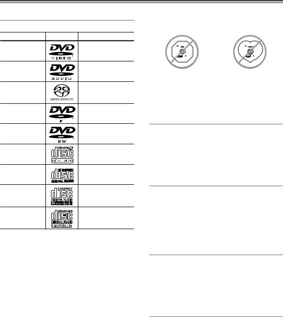
•Don’t use discs with an unusual shape, such as those shown below, because you may damage the DVD receiver.
•Don’t use discs that have residue from adhesive tape, rental discs with peeling labels, or discs with custommade labels or stickers. Doing so may damage the DVD receiver and you may not be able to remove the disc properly.
Discs Made on Personal Computers
Discs made on personal computers, including those of a compatible format, may not work properly in the DVD receiver because of incorrect settings in the disc burning software. Check the manuals supplied with your disc burning software for additional compatibility information.
CD-R/RW compatibility
•Compatible formats: CD-Audio, Video CD, ISO 9660 CD-ROM* containing MP3, WMA or JPEG files
*ISO 9660 Level 1 or 2 compliant. CD physical format: Mode1, Mode2 XA Form1. Romeo and Joliet file systems are both compatible with this player.
•Multi-session playback: No
•Unfinalized disc playback: No
DVD-R/RW compatibility
•Compatible formats: DVD-Video, Video Recording (VR)*
*Edit points may not play exactly as edited; screen may go momentarily blank at edited points.
•Unfinalized playback: No
•WMA/MP3/JPEG file playback on DVD-R/RW: No
Compressed audio compatibility
•Compatible formats: MPEG-1 Audio Layer 3 (MP3), Windows Media Audio (WMA)
•Sampling rates: 32, 44.1 or 48kHz
•Bit-rates: Any (128Kbps or higher recommended)
•VBR (variable bit rate) MP3 playback: No
•VBR WMA playback: No
•WMA lossless encoding compatible: No
•DRM (Digital Rights Management) compatible: Yes (DRM-protected audio files will not play in this player.)
•File extensions: .mp3, .wma (these must be used for the player to recognize MP3 and WMA files – do not use for other file types)
•File structure: Up to 299 folders; up to 648 folders and files combined
8
Disc Notes—Continued
About WMA
WMA is an acronym for Windows Media Audio and refers to an audio compression technology developed by Microsoft Corporation. WMA content can be encoded by using Windows Media® Player version 7, 7.1, Windows Media® Player for Windows® XP, or Windows Media® Player 9 Series.
JPEG file compatibility
•Compatible formats: Baseline JPEG and EXIF 2.2* still image files up to a resolution of 3072 x 2048.
*File format used by digital still cameras
•Progressive JPEG compatible: No
•File extensions: .jpg (must be used for the player to recognize JPEG files – do not use for other file types)
•File structure: Up to 299 folders; up to 648 folders and files combined
Copyright
It is forbidden by law to copy, broadcast, show, broadcast on cable, play in public, or rent copyrighted material without permission.
DVD-Video discs are copy-protected, and any recordings made from these discs will be distorted.
This product incorporates copyright protection technology that is protected by U.S. patents and other intellectual property rights. Use of this copyright protection technology must be authorized by Macrovision Corporation, and is intended for home and other limited consumer uses only unless otherwise authorized by Macrovision. Reverse engineering or disassembly is prohibited.
Handling Discs
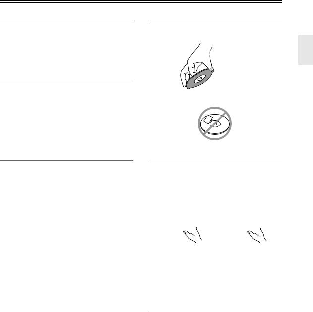
•Never touch the underside of a disc. Always hold discs by the edge, as shown.
 Underside
• Never attach adhesive tape or sticky labels to discs.
Cleaning Discs
•For best results, keep your discs clean. Fingerprints and dust can affect the sound and picture quality and should be removed as follows. Using a clean soft cloth, wipe from the center outwards, as shown. Never wipe in a circular direction.


•To remove stubborn dust or dirt, wipe the disc with a damp soft cloth, and then dry it with a dry cloth.
•Never use solvent-based cleaning fluids, such as thinner or benzine, commercially available cleaners, or antistatic sprays intended for vinyl records, because they may damage the disc.
Storing Discs
•Don’t store discs in places subject to direct sunlight, or near heat sources.
•Don’t store discs in places subject to moisture or dust, such as in a bathroom or near a humidifier.
•Always store discs in their cases and vertically. Stacking, or putting objects on unprotected discs may cause warping, scratches, or other damage.
9

Remote Controller
Installing the Batteries
1 To open the battery compartment, press the small hollow and slide off the cover.
2 Insert the two supplied batteries (AA/R6) in accordance with the polarity diagram inside the battery compartment.
3 Put the cover onto the remote controller and slide it shut.
Notes:
•If the remote controller doesn’t work reliably, try replacing the batteries.
•Don’t mix new and old batteries or different types of batteries.
•If you intend not to use the remote controller for a long time, remove the batteries to prevent damage from leakage or corrosion.
•Expired batteries should be removed as soon as possible to prevent damage from leakage or corrosion.
Using the Remote Controller
To use the remote controller, point it at the DVD receiver’s remote control sensor, as shown below.
Remote control sensor
. ft .16 Approx m) (5
DVD receiver
Notes:
•The remote controller may not work reliably if the DVD receiver is subjected to bright light, such as direct sunlight or inverter-type fluorescent lights. Keep this in mind when installing.
•If another remote controller of the same type is used in the same room, or the DVD receiver is installed close to equipment that uses infrared rays, the remote controller may not work reliably.
•Don’t put anything, such as a book, on the remote controller, because the buttons may be pressed inadvertently, thereby draining the batteries.
•The remote controller may not work reliably if the DVD receiver is installed in a rack behind colored glass doors. Keep this in mind when installing.
•The remote controller will not work if there’s an obstacle between it and the DVD receiver’s remote
control sensor.
10
Part Names and Functions
Front Panel
1 |
|
Display |
2 |
3 |
|
|
||||
|
|
|
||||||||
|
|
|
|
|
|
|
|
|
|
|
|
|
|
|
|
|
|
|
|
|
|
|
|
|
|
|
|
|
|
|
|
|
|
|
|
|
|
|
|
|
|
|
|
|
|
|
|
|
|
|
|
|
|
|
4 5 6 7 8 9 J K L M N O P Q R |
The page numbers in parentheses show where you can find the main explanation for each item.
ARemote control sensor (10)
Receives signals from the remote controller.
BINPUT/CURSOR buttons (27, 28, 44, 48, 50, 80)
Enable you to select an input source. These buttons also move the cursor when you input characters.
CVOLUME control (26)
Adjusts the volume level.
DSTANDBY indicator (26)
Lights up in Standby mode.
ESTANDBY/ON button (26, 62, 67)
Press this button to turn on the power to the unit or place the unit in Standby mode.
FPHONES jack (27)
Connect a headphone mini plug here.
GDVD disc tray (31)
Place a DVD in the disc tray.
HLISTENING MODE button (59)
Use this button to select the listening modes.
IS.BASS button (60)
Use this button to adjust the low end bass range.
J /
/ buttons (32, 44)
LTIMER button (62, 64, 65, 68)
Press this button to enable the timer function or set current time.
MMULTI JOG dial (28, 32, 33, 47, 48, 50)
Turn the dial to select a programmed station, playback track or groups. It also assists you to choose an edit type, and to select characters when you enter characters. Press it to confirm the current setting.
NYES/MODE button (42, 49, 54)
Press this button to confirm the displayed settings for playback and other editing operations.
OEDIT/NO/CLEAR button (28, 47-49, 52-54)
Enables you to adjust settings for playback and select editing operations. It also cancels the displayed setting.
PDVD  /
/ 
 button (32)
Starts or pauses DVD playback.When you press this button during playback, the unit enters Pause mode.
QDVD  button (32)
Stops DVD playback.
RDVD  button (31)
Ejects a loaded DVD.
Fast-forward or reverse the track being played. These buttons also move the cursor when you input characters.
KDISPLAY button (41, 46, 51, 54, 57)
Each time you press this button, the information on the display changes. This button also enables you to select the input character type.
11
Part Names and Functions—Continued
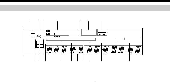
Display
1 2 3 |
4 |
5 |
6 |
7 |
MUTING |
DIGITAL DTS AAC PCM |
DVD - AUDIO |
D V D |
|
|||
S.BASS |
PL |
T - D DSP STEREO |
VCD SACD |
|
|
||
|
|
AUTO |
FM ST |
RDS |
|
|
|
TIMER |
MEM RDM |
NORMAL REPEAT 1 |
|
TRACK NAME |
|||
1 |
2 |
|
GROUP |
TITLE |
CHP TRACK |
PRGSV |
DISC TOTAL REMAIN |
3 |
4 |
|
|
|
|
|
|
SLEEP |
|
|
|
|
|
|
|
8 9 J K L M N O P |
Q |
AS.BASS indicator
This indicator lights up when the super bass is selected.
BMUTING indicator
This indicator flashes while the DVD receiver is muted.
CTuning indicators

 : This indicator lights up when the DVD receiver is tuned into a radio station.
AUTO: This indicator lights up when the Auto Tuning mode is selected, and disappears when the Manual Tuning mode is selected.
FM ST: This indicator lights up when the DVD receiver is tuned to a stereo FM station.
JTIMER indicators
These indicators show the status of the timers.
 : Lights up when timed recording has been set.
Numbers 1-4: Lights up when a timer has been set.
KGROUP indicators
This indicator lights up when the Group number is displayed.
LTITLE indicator
During playback, the number of the current title is displayed.
MMessage area
Various information is displayed here, including preset number, tuning frequency, time, volume level, sleep time, mode settings, and so on.
D Listening mode & format indicators |
N CHP indicator |
These indicators show the currently selected listening mode and the format of digital input signals.
EPlayback mode indicators
MEM: Lights up when memory playback is selected.
RDM: Lights up when random playback is selected.
NORMAL: Lights up when normal playback is selected.
This indicator appears while the number of the current chapter is being displayed.
OTRACK indicators
This indicator lights up when the track number is displayed.
PPRGSV (PROGRESSIVE) indicator
This indicator appears when the Progressive Scanning function is on.
QDVD information indicators
REPEAT: Lights up when repeat playback is selected for all the tracks.
REPEAT 1: Lights up when repeat playback is selected for a track.
FDisc type indicators
These indicators show the type of disc loaded.
GDVD operation indicators
These indicators show the status of DVD playback.
HCamera angle  indicator
This indicator appears if the DVD-Video disc being played features multiple camera angles.
ISLEEP indicator
This indicator lights up when the Sleep function has been set.
The item lights up, which corresponds to the information in the message area.
12
Part Names and Functions—Continued
Rear Panel
1BC D 5 |
|
6 |
|
||||||||||||||||||||||||||||||||||
|
|
|
|
|
|
|
|
|
|
|
|
|
|
|
|
|
|
|
|
|
|
|
|
|
|
|
|
|
|
|
|
|
|
|
|
|
|
|
|
|
|
|
|
|
|
|
|
|
|
|
|
|
|
|
|
|
|
|
|
|
|
|
|
|
|
|
|
|
|
|
|
|
|
|
|
|
|
|
|
|
|
|
|
|
|
|
|
|
|
|
|
|
|
|
|
|
|
|
|
|
|
|
|
|
|
|
|
|
|
|
|
|
|
|
|
|
|
|
|
|
|
|
|
|
|
|
|
|
|
|
|
|
|
|
|
|
|
|
|
|
|
|
|
|
|
|
|
|
|
|
|
|
|
|
|
|
|
|
|
|
|
|
|
|
|
|
|
|
|
|
|
|
|
|
|
|
|
|
|
|
|
|
|
|
|
|
|
|
|
|
|
|
|
|
|
|
|
|
|
|
|
|
|
|
|
|
|
|
|
|
|
|
|
|
|
|
|
|
|
|
|
|
|
|
|
|
|
|
|
|
|
|
|
|
|
|
|
|
|
|
|
|
|
|
|
|
|
|
|
|
|
|
|
|
|
|
|
|
|
|
|
|
|
|
|
|
|
|
|
|
|
|
|
|
|
|
|
|
|
|
|
|
|
|
|
|
|
|
|
|
|
|
|
|
|
|
|
|
|
|
|
|
|
|
|
|
|
|
|
|
|
|
|
|
|
|
|
|
|
|
|
|
|
|
|
|
|
|
|
|
|
|
|
|
|
|
|
|
|
|
|
G
8
9
J K L M
The page numbers in parentheses show where you can find the main explanation for each item.
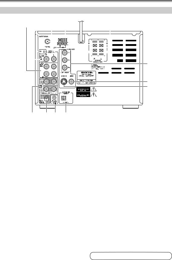
ATAPE/HDD IN/OUT (21, 22)
This analog audio input and output are for connecting a recorder with an analog audio input and output (cassette, Mini Disc, etc.). If you want to connect Onkyo RI Dock, connect the RI Doc output with the TAPE/HDD IN terminal.
BLINE/TV IN (23)
These terminals are for connecting audio output of external devices such as TV, DVD or turntable with a built-in phono equalizer.
CXM ANTENNA (44)
This jack is for connecting an XM antenna, sold separately.
DFM ANTENNA (16, 17)
This jack is for connecting an FM antenna.
EAM ANTENNA (16,17)
These push terminals are for connecting an AM antenna.
FFRONT SPEAKERS (18)
These terminals are for connecting speakers.
GVIDEO OUT COMPONENT VIDEO (20)
These jacks output component video and can be connected to an component video input on a TV or projector.
HVIDEO OUT VIDEO (20)
This RCA connector can be used to connect a TV or projector with a composite video input.
IVIDEO OUT S VIDEO OUT (20)
This connector can be used to connect a TV or projector with an S Video input.
JPRE OUT (23, 25)
These terminals are for connecting a power amplifier.
KSUBWOOFER CONTROL
This terminal is provided for future use with Onkyo subwoofer equipped with SUBWOOFER CONTROL terminals. No product is available as of August 2005.
L
 REMOTE CONTROL (21, 22)
This 
 (Remote Interactive) jack can be connected to an
 jack on another Onkyo AV component. The DVD receiver’s remote controller can
then be used to control that component. To use 
 , you must make an analog audio connection (RCA) between the DVD receiver and the other AV component, even if they are connected digitally.
MAUDIO IN DIGITAL OPTICAL (22)
This optical digital terminal can be used for connecting any game machine or satellite tuner equipped with digital output terminals. Connect any of them using a commercially available audio optical digital cable.
See pages 16-25 for connection information.
13
Part Names and Functions—Continued
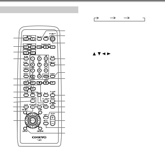
Remote Controller
This section describes the role of the individual buttons you use to control the amplifier and the tuner.
IDIMMER button (27)
Adjusts the display brightness.
normal dim dimmer
|
|
J TIMER button (62, 65, 68) |
|||||
|
M |
|
Press this button to enable the timer function or set |
||||
A |
N |
|
current time. |
|
|||
K RCV SETUP button (56, 61) |
|||||||
|
|||||||
|
O |
||||||
2 |
|
Press this button to configure settings for the DVD |
|||||
|
|
||||||
|
|
receiver. |
|
|
|||
3 |
|
|
|
|
|||
|
L |
/ |
/ |
/ |
/ENTER buttons (45, 46, 56, 57) |
||
|
|
||||||
4 |
P |
|
These buttons are used to select and adjust settings. |
||||
|
Q |
M CLOCK button (62) |
|||||
|
|
Press this button to display the current time. |
|||||
|
|
|
|||||
|
R |
N SLEEP button (64) |
|||||
5 |
S |
|
Used to program the Sleep timer, which turns off |
||||
6 |
|
|
the power to the unit at a specified time. |
||||
|
O STANDBY/ON button (26, 67) |
||||||
|
|
||||||
7 |
T |
|
Switches between power standby and on. |
||||
8 |
P NAME button (55) |
||||||
U |
|||||||
9 |
|
Used to input characters when you give a name to |
|||||
J |
V |
|
each FM/AM preset channel. |
||||
|
|
|
|
|
|||
K |
W |
Q DISPLAY button (46, 51, 55, 57, 62) |
|||||
|
|
|
Each time you press this button, the information on |
||||
L |
X |
|
the display changes. It also selects the character |
||||
|
Y |
|
input type. |
|
|||
|
R ENTER button (55) |
||||||
|
Z |
||||||
|
|
Press this button to confirm the current setting. |
|||||
The page numbers in parentheses show where you can find the main explanation for each item.
AINPUT buttons (27, 42, 45, 46, 80)
Each time you press these buttons, the input source switches.
BPRESET 
 /
/
 buttons (50)
These buttons select programmed stations.
CTUNING  /
/ buttons (42, 45, 46)
These buttons tune in a broadcast station or move the cursor when you input characters.
DMODE button (42, 45)
This button is used to select the Auto or Manual tuning mode.
ENumber buttons (50, 55)
Used to name a preset station.
FLATE NIGHT button (60)
Switches the dynamic range for playback at minimum volume.
GCH SEL button (60)
Selects the speakers.
HTEST TONE button (57)
Outputs the test tone.
SCLEAR button (54)
Cancels the settings, and erases a character.
TSTEREO/T-D button (59)
Switches over between Stereo Sound and Theater Dimensional Surround.
UALL CH STEREO button (59)
This button is used to select the All Ch Stereo listening mode. It is operable when center/surround speakers are connected.
VLISTENING MODE button (59)
Selects the listening mode.
WS.BASS button (60)
Adjusts the low end bass range.
XVOLUME +/– buttons (26)
Adjust the volume level.
YMUTING button (27)
Lowers the volume level temporarily.
ZRETURN button (45, 56, 57)
This button is used to return to the previously selected menu.
14
Part Names and Functions—Continued
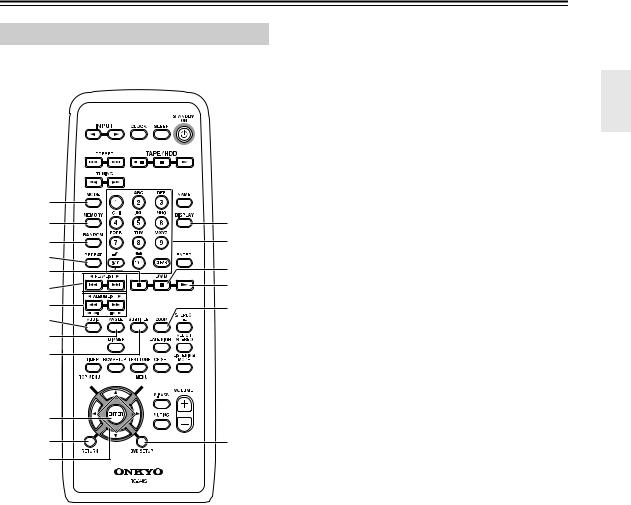
Remote Controller
This section describes the role of the individual buttons you use to control DVD and CD.
1 |
|
2 |
O |
3 |
P |
4 |
Q |
5 |
|
6 |
R |
|
|
7 |
S |
8 |
|
9 |
|
J |
|
K
 T
T
L |
|
M |
U |
N |
|
The page numbers in parentheses show where you can find the main explanation for each item.
AMODE button (38, 39, 40)
Switches the play mode while DVD is loaded.
BMEMORY button (38)
This button is used with the memory playback function, which allows you to create a custom playlist of titles, chapters, or tracks.
CRANDOM button (39)
This button is used with the random playback function.
DREPEAT button (40)
Repeats playback or RI Dock playback.
EPause 
 button (32, 34, 41)
This button is used to pause playback.
FPrevious/Next 
 /
/
 buttons (32, 33, 41)
The Previous button is used to select the previous chapter or track. During playback it selects the beginning of the current chapter or track.
The Next button is used to select the next chapter or track
G /
/ buttons (32, 34)
Fast-forward or reverve being played.
HAUDIO button (35)
This button is used to select foreign language soundtracks and audio formats (e.g., Dolby Digital or DTS) on DVD-Video discs.
For Video CDs you can select left-channel, rightchannel, or stereo.
IANGLE button (35)
This button is used to select camera angles on DVD-Video discs.
JSUBTITLE button (35)
This button is used to select subtitles on DVD-Video discs.
KTOP MENU button (32)
This button is used to display the top menu on a DVD-Video disc.
LENTER button (29, 32, 70, 73, 74)
This button is used to start playback of the selected title, chapter, or track, and to confirm settings.
MRETURN button (29, 32, 33)
This button is used to return to the main menu without saving your changes.
NArrow [ ]/[
]/[ ]/[
]/[ ]/[
]/[ ] buttons (29, 32, 41, 70, 76)
These buttons are used to select items on the onscreen setup menus.
ODISPLAY button (41)
Each time you press this button, the information on the display changes.
PNumber buttons and CLEAR button (32, 38, 73, 74)
You can select a track or sort tracks for Memory playback by using the number buttons. You can cancel the setting by pressing the CLEAR.
QStop  button (32)
This button is used to stop playback.
RPlay  button (31-34)
This button is used to start playback.
SZOOM button (35, 41)
This button is used with the Zoom function.
TMENU button (32, 41)
This button is used to display the menu on a DVD-Video disc or to open the Disc Navigator when using a Video CD, audio CD, WMA/MP3/ JPEG disc, or VR format DVD-RW disc.
UDVD SETUP button (29, 36, 37, 69, 70)
This button is used to access the DVD player’s onscreen setup menus.
15

Connecting Antenna
This section explains how to connect the supplied indoor FM antenna and AM loop antenna, and how to connect commercially available outdoor FM and AM antennas.
The DVD receiver won’t pick up any radio signals without any antenna connected, so you must connect the antenna to use the tuner.
AM antenna push terminals
FM antenna |
connector |
Connecting the Indoor FM Antenna
The supplied indoor FM antenna is for indoor use only.
1 |
Attach the FM antenna, as shown. |
|
■ North American Model |
Insert the plug fully into the jack.
■ Other Models
Insert the plug fully into the jack.
Once your DVD receiver is ready for use, you’ll need to tune into an FM radio station and adjust the position of the FM antenna to achieve the best possible reception.
2 Use thumbtacks or something similar to fix the FM antenna into position.
Thumbtacks, etc.
Caution: Be careful that you don’t injure yourself when using thumbtacks.
If you cannot achieve good reception with the supplied indoor FM antenna, try a commercially available outdoor FM antenna instead (see page 17).
Connecting the AM Loop Antenna
The supplied indoor AM loop antenna is for indoor use only.
1 Assemble the AM loop antenna, inserting the tabs into the base, as shown.
2 Connect both wires of the AM loop antenna to the AM push terminals, as shown.
(The antenna’s wires are not polarity sensitive, so they can be connected either way around.) Make sure that the wires are attached securely and that the push terminals are gripping the bare wires, not the insulation.
Push |
Insert wire |
Release |
Once your DVD receiver is ready for use, you’ll need to tune into an AM radio station and adjust the position of the AM antenna to achieve the best possible reception.
Keep the antenna as far away as possible from your DVD receiver, TV, speaker cables, and power cords.
If you cannot achieve good reception with the supplied indoor AM loop antenna, try using it with a commercially available outdoor AM antenna (see page 17).
16
Connecting Antenna—Continued
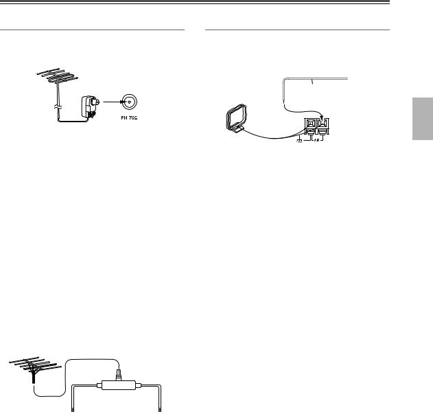
Connecting an Outdoor FM Antenna
If you cannot achieve good reception with the supplied indoor FM antenna, try a commercially available outdoor FM antenna instead.
Connecting an Outdoor AM Antenna
If good reception cannot be achieved using the supplied AM loop antenna, an outdoor AM antenna can be used in addition to the loop antenna, as shown.
Outdoor antenna
Insulated antenna cable
AM loop antenna
Notes:
•Outdoor FM antennas work best outside, but usable results can sometimes be obtained when installed in an attic or loft.
•For best results, install the outdoor FM antenna well away from tall buildings, preferably with a clear line of sight to your local FM transmitter.
•Outdoor antenna should be located away from possible noise sources, such as neon signs, busy roads, etc.
•For safety reasons, outdoor antenna should be situated well away from power lines and other high-voltage equipment.
•Outdoor antenna must be grounded in accordance with local regulations to prevent electrical shock hazards.
■ Using a TV/FM Antenna Splitter
It’s best not to use the same antenna for both FM and TV reception, as this can cause interference problems. If circumstances demand it, use a TV/FM antenna splitter, as shown.
Outdoor AM antennas work best when installed outside horizontally, but good results can sometimes be obtained indoors by mounting horizontally above a window. Note that the AM loop antenna should be left connected.
Outdoor antenna must be grounded in accordance with local regulations to prevent electrical shock hazards.
TV/FM antenna splitter
To DVD receiver |
To TV (or VCR) |
17

Connecting Your Speakers
Connecting Speaker
1 |
Strip 3/8" (10 mm) of insu- |
3/8" (10 mm) |
|
lation from the ends of the |
|
|
speaker cables, and twist the |
|
|
bare wires tightly, as shown. |
|
2 |
While pressing the lever, insert |
|
the wire into the hole, and then release the lever.
Make sure that the terminals are gripping the bare wires, not the insulation.
The following illustration shows which speaker should be connected to each pair of terminals.
Speaker Connection Precautions
Read the following before connecting your speakers:
•You can connect speakers with an impedance of
4 ohms or higher. If you use speakers with a lower impedance, and use the amplifier at high volume levels for a long period of time, the built-in protection circuit may be activated.
•Disconnect the power cord from the wall outlet before making any connections.
•Read the instructions supplied with your speakers.
•Pay close attention to speaker wiring polarity. In other words, connect positive (+) terminals to only positive
(+) terminals, and negative (–) terminals to only negative (–) terminals. If you get them the wrong way around, the sound will be out of phase and will sound unnatural.
•Unnecessarily long, or very thin speaker cables may affect the sound quality and should be avoided.
•Be careful not to short the positive and negative wires.
Doing so may damage the AV
receiver.
• Don’t connect more than one
cable to each speaker termi-
nal. Doing so may damage the AV receiver.
• Don’t connect one speaker to several terminals.
Front right |
Front left |
speaker |
speaker |
18

AV Cables and Connectors
Before Making Any Connections
•Read the manuals supplied with your AV components.
•Don’t connect the power cord until you’ve completed all audio and video connections.
• Do not place objects on the unit as they may interfere with proper ventilation.
Optical Digital Connectors
The DVD receiver’s optical digital connectors have a shutter-type cover that opens when an optical plug is inserted, and closes when it’s removed. Push the plug in all the way.
Caution: To prevent shutter damage, hold the optical plug straight when inserting and removing.
RCA AV Connection Color Coding
RCA AV connections are usually color coded: red, white, and yellow. Use red plugs to connect right-chan- nel audio inputs and outputs (typically labeled “R”). Use
white plugs to connect left-channel audio inputs and outputs (typically labeled “L”). And use yellow plugs to connect composite video inputs and outputs.
The supplied AV cable is made up of an analog audio cable and a composite video cable.
|
Analog audio |
Right (red) |
Right (red) |
Left (white) |
Left (white) |
|
Composite video |
(Yellow)
•Push each plug in all the way to make a good connection (loose connections can cause noise or malfunctions).
•To prevent interference, keep audio and video cables away from power cords and speaker cables.
 (Yellow)
 Right!
 Wrong!
AV Cables & Connectors
Video
|
Y |
Y |
Component video separates the luminance (Y) and |
|
|
color difference signals (PR, PB), providing the best |
|||
Component |
PB /CB |
PB / CB |
||
picture quality. Some TV manufacturers label their |
||||
video |
|
|
||
PR / CR |
PR / CR |
component video inputs differently. |
||
|
||||
|
|
|
S Video provides better picture quality than com- |
|
S Video |
|
|
posite video. |
|
Composite |
|
|
Composite video can be found on virtually all TVs, |
|
|
|
VCRs, and video equipment. |
||
video |
|
|
||
|
|
|
Audio
Optical digital
Analog
Optical digital audio connections provide better audio quality than analog connections.
RCA analog audio connectors can be found on virtually all AV components.
19
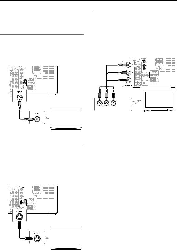
Connecting Your TV
Connect the DVD receiver to the TV directly. If you connect the DVD receiver to a VCR, TV/VCR combination, or video selector, the playback picture may be distorted as DVD videos are copy protected.
Using Video
Connect the VIDEO OUT to a set of VIDEO input on your TV.
Use the supplied video cable (RCA), connecting the yellow plug to the video output.
See the following page if you want to use a component or S Video cable for the video connection.
Using Component Video
You can use the component video output instead of the standard video out jack to connect this player to your TV (or other equipment).
This should give you the best quality picture from the three types of video output available.
•Use a component video cable (not supplied) to connect the COMPONENT VIDEO OUTPUT jacks to a component video input on your TV, monitor or AV receiver.
TV
COMPONENT
VIDEO IN
Y PB PR
TV
Video cable (Supplied)
Using S Video
If your TV (or other equipment) has an S Video input, you can use this instead of the standard (composite) output for a better quality picture.
•Use an S Video cable (supplied) to connect the S VIDEO OUTPUT to an S Video input on your TV (or monitor or AV receiver).
Line up the small triangle above the jack with the same mark on the plug before plugging in.
Note:
Watching progressive scan video from the component video outputs.
This player can output progressive scan video from the component video output. Compared to interlace video, progressive scan video effectively doubles the scanning rate of the picture, resulting in a very stable, flicker-free image. To set up the player for use with a progressive scan TV, see Video Output settings on page 70. When the player is set to output progressive scan video, the PRGSV indicator lights in the front panel display.
Important:
If you connect a TV that is not compatible with a progressive scan signal and switch the player to progressive, you will not be able to see any picture at all. In this case, return the setting from “Progressive” to “Interlace” by following the way described in Note on page 70.
TV
S-Video cable (Not supplied)
20
Connecting External Devices
Connect the white plugs of the audio cables to the L jacks and connect the red plugs of the audio cables to the R jacks. Tip: The source names appearing in the display can be customized for the connected component (see page 28).
Connecting an Onkyo Stereo Cassette Tape Deck
The following diagram illustrates how to connect an optional Onkyo stereo cassette tape deck.
Connect the DVD receiver’s TAPE/HDD OUT jacks to the tape deck’s INPUT (REC) jacks, and the DVD receiver’s TAPE/HDD IN jacks to the tape deck’s OUTPUT (PLAY) jacks.
DVD receiver’s rear panel |
Onkyo stereo cassette |
tape deck rear panel |
INPUT OUTPUT |
(REC) (PLAY) |
REMOTE |
red |
CONTROL |
L
 white
white
|
RCA/phono audio cable |
white |
|
red |
cable supplied |
|
with the Onkyo stereo |
|
cassette tape deck |
R
white red red white
: Signal flow |
Use either socket |
|
|
|
|
What does connecting an Onkyo stereo cassette tape deck using an |
cable enable you to do? |
|
•You can control a connected Onkyo stereo cassette tape deck using the supplied remote controller. You also need to connect the RCA/phono audio cable.
• To operate the  system, the source name in the display should be TAPE. (Since the default source name in the display is TAPE, you do not need to change the setting. See page 28 for further information.)
•When the connected Onkyo stereo cassette tape deck plays back, the Input Selector on the DVD receiver is automatically switched to TAPE.
Connecting an RI Dock (Remote Interactive Dock)
The following diagram illustrates how to connect the Onkyo DS-A1 which is sold separately. Connect the TAPE/HDD IN jacks on the DVD receiver to the AUDIO OUT jacks on the RI Dock.
DVD receiver’s rear panel |
|
white |
|
|
|
|
red |
|
|
|
RCA/phono audio cable |
|
|
|
|
red |
|
R ---- L |
|
|
|
S VIDEO OUT AUDIO OUT |
DC IN |
|
|
|
|
||
|
white |
|
Jacks on the RI Dock’s rear |
|
|
cable |
panel |
|
|
|
|
|
||
|
|
|
|
 : Signal flow
The jack connection enables you to use the following functions:
•You can control a connected Onkyo RI Dock using the supplied remote controller. You also need to connect the RCA/ phono audio cable.
• When a RI Dock and other |
|
-compatible devices are connected with the DVD receiver, you must also interconnect |
||
|
||||
the |
|
terminals between the two external devices. |
||
|
||||
|
||||
•You need to change the source name in the display to HDD. (The default source name in the display is TAPE. See page 28 for further information.) If the HDD device has a MODE switch, you must set the switch to HDD.
•When the connected Onkyo RI Dock plays back, the input selector on the DVD receiver is automatically switched to HDD.
21

Connecting External Devices—Continued
Connection for Listening to Sound from Digital Device through DVD receiver
Connect the DVD receiver’s DIGITAL IN terminal with a digital audio output terminal on any digital device such as satellite tuner or PC.
Optical digital audio cable |
Satellite tuner |
|
DIGITAL
OUTPUT
PC
: Signal flow
Connect the DVD receiver’s DIGITAL IN terminal with a digital audio output terminal on an audio processor.
If you want to connect an Onkyo audio processor equipped with RI terminal, make sure to connect the DVD receiver’s TAPE/HDD IN terminal with a line output terminal of the audio processor. And connect the DVD receiver’s TAPE/HDD OUT terminal with a line input terminal of the audio processor.
 cable
cable
|
Audio Processor |
|||
DIGITAL |
|
|
|
|
OUTPUT |
|
|
|
|
LINE |
R |
L |
R |
L |
|
|
|
LINE |
|
OUT |
|
|
|
IN |
Optical digital audio cable |
red |
white |
red |
white |
white red red white
: Signal flow
You can enjoy the following features by connecting the  terminal:
You can control a part of the DVD receiver’s operations by using the accompanying remote controller of the Onkyo audio processor. (Standby/On, Input switch over, Volume control, Muting, Tuner control and Sound quality adjustment.)
Notes:
•You must change the display title for the external input from “TAPE” to “PC”. (See “Customizing the Source Names” on page 28.)
•You can not control any Onkyo audio processor by using the supplied remote controller of the DVD receiver.
•If you have connected an optical audio digital cable and an audio pin code, you must change the display title from “DIGITAL” to “PC/dig”.
•If you playback your PC device through an Onkyo audio processor, the input of the DVD receiver will be changed to “PC” automatically.
22
Connecting External Devices—Continued
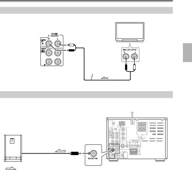
Connection for TV Audio Signal
Connect the LINE IN terminal on the DVD receiver and an audio output terminal on TV.
DVD receiver’s rear panel
white
red
RCA/phono |
red |
white |
audio cable |
|
|
 : Signal flow
Connecting a subwoofer
The DVD receiver has a SUBWOOFER PRE OUT jack. Connect an active subwoofer (a subwoofer that contains an amplifier).
DVD receiver
Active subwoofer
(with a built-in amplifier)
: Signal flow
Note:
If you want to connect any passive subwoofer, you must connect at first a power amplifier with the DVD receiver, and then connect a subwoofer to the power amplifier.
23
Connecting External Devices—Continued
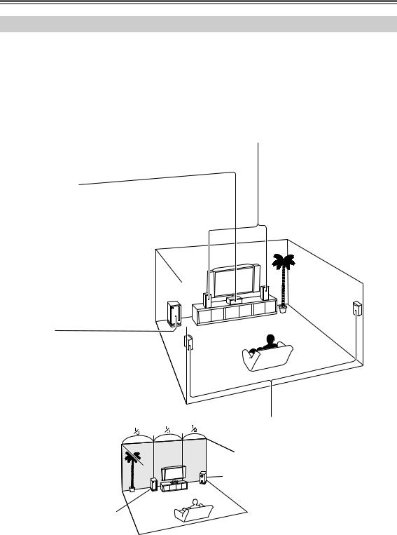
Enjoying Home Theater
The DVD receiver provides multi-channel playback with its theater dimensional feature, even under two front speaker conditions.
Certainly, it can provide full 5.1ch playback in combination with an add-on subwoofer, center and surround speakers off the shelf, so that you can enjoy more realistic, movie theater/concert hall-in-the-home sound effect.
With DVDs you can enjoy DTS and Dolby Digital. With analog and digital TV you can enjoy Onkyo’s own DSP surround listening modes.
Front left and right speakers
These output the overall sound. Their role in a home theater is to provide a solid anchor for the sound image. They should be positioned facing the listener at about ear level, and equidistant from the TV. Angle them inward so as to create a triangle, with the listener at the apex.
Center speaker
This speaker enhances the front left and right speakers, making sound movements distinct and providing a full sound image. In movies it’s used mainly for dialog.
Position it close to your TV (preferably on top) facing forward at about ear level, or at the same height as the front left and right speakers.
Subwoofer
The subwoofer handles the bass sounds of the LFE (Low-Frequency Effects) channel. The volume and quality of the bass output from your subwoofer will depend on its position, the shape of your listening room, and your listening position. In general, a good bass sound can be obtained by installing the subwoofer in a front corner, or at one-third the width of the wall, as shown.
1/3 wall length
Surround left and right speakers
These speakers are used for precise sound positioning and to add realistic ambience.
Position them at the sides of the lis-
tener, or slightly behind, about 2–3 Corner feet (60–100 cm) above ear level.
Ideally they should be equidistant from the listener.
•For optimum surround playback, set the distance between the listener and the speakers so that the time it takes the sound to reach the listener is same. Also, you need to set each speaker volume level individually in order to balance the volume level between speakers (see pages 56-57).
24

Connecting External Devices—Continued
Connection for Enjoying 5.1ch Playback
You can connect a center speaker and a left and a right surround speakers by adding on a power (main) amplifier. In addition to this configuration, you can add on a subwoofer to enjoy the 5.1ch surround sound. (See page 23.)
Once you have completed the connection, make sure to configure the settings for speakers, described on page 56, so that you can enjoy your favorite surround mode.
DVD receiver |
|
|
CENTER |
SURROUND |
SURROUND |
LEFT |
RIGHT |
|
MAIN IN |
MAIN IN |
MAIN IN |
OUTPUT |
OUTPUT |
OUTPUT |
Power amplifier
|
|
|
|
|
|
|
|
|
|
|
|
|
|
|
|
|
|
|
|
|
|
|
|
|
|
|
|
|
|
|
|
|
|
|
|
|
|
|
|
|
|
|
|
|
|
|
|
|
|
|
|
|
|
|
|
|
|
|
|
|
|
|
|
|
|
|
|
|
|
|
|
|
|
|
|
|
|
|
|
|
|
|
|
|
|
|
|
|
|
|
|
|
|
|
|
|
|
|
|
|
|
|
|
|
|
|
|
|
|
|
|
|
|
|
|
|
|
|
|
|
|
|
|
|
|
|
|
|
|
|
|
|
|
|
|
|
|
|
|
|
|
|
|
|
|
|
|
|
|
|
|
|
|
|
|
|
|
|
|
|
|
|
|
|
|
|
|
|
|
|
|
|
|
|
|
|
|
|
|
|
|
|
|
|
|
|
|
|
|
|
|
|
|
|
|
|
|
|
|
|
|
|
|
|
|
|
|
|
|
|
|
|
|
|
|
|
|
|
|
|
|
|
|
|
|
|
|
|
|
|
|
|
|
|
|
|
|
|
|
|
|
|
|
|
|
|
|
|
|
|
|
|
|
|
|
|
|
|
|
|
|
|
|
|
|
|
|
|
|
|
|
|
|
|
|
|
|
|
|
|
|
|
|
|
|
|
|
|
|
|
|
|
|
|
|
|
|
|
|
|
|
|
|
|
|
|
|
|
|
|
|
|
|
|
|
|
Active |
Front right |
Center speaker |
Front left |
Surround right |
Surround left |
|||||||||||||||||||||||||||||||||||||||||||||||||||||||
(Powered) |
speaker |
|
|
|
|
|
|
|
|
|
|
|
|
speaker |
speaker |
speaker |
||||||||||||||||||||||||||||||||||||||||||||||
subwoofer |
|
|
|
|
|
|
|
|
|
|
|
|
|
|
|
|
|
|
|
|
|
|
|
|
|
|
|
|
|
|
|
|
|
|
|
|
|
|
|
|
|
|
|
|
|
|
|
|
|
|
|
|
|
|
|
|
|
|
||||
25
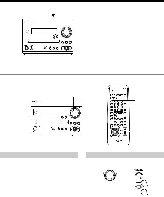
Connecting the Power Cord
|
|
|
|
When the power cord is connected to the AC outlet, the |
|
|
To wall outlet |
DVD receiver enters Standby mode. The STANDBY |
|
|
|
|
|
indicator lights up. |
|
|
|
|
|
|
|
|
|
|
|
|
|
|
|
STANDBY 


 indicator
Understanding Common Operations
VOLUME |
INPUT buttons
STANDBY/ON 

STANDBY indicator


 STANDBY/


 ON
ON
INPUT buttons
VOLUME |
+/– |
Turning the Unit On and Off
Press STANDBY/ON on the unit or on the remote controller.
If you press the same button again, the unit will turn off and enter Standby mode.
The DVD receiver is not completely shutdown in Standby mode.
To completely shut down the DVD receiver, disconnect the power cord from wall outlet.
Tip:
•When you start playing (or turn on the power to) an Onkyo RI Dock, CD recorder or cassette tape deck that is connected to the DVD receiver via an 
 cable and RCA/phono audio cables, the power to the DVD receiver is automatically turned on. Also, if you turn on or off the power to the DVD receiver, the power to such a device is automatically turned on or off (standby).
Adjusting the Volume
DVD receiver |
Remote |
|
controller |
Turn VOLUME clockwise to increase the volume or counterclockwise to decrease the volume on the DVD receiver.
Press VOLUME +/– on the remote controller.
26
 Loading...