


DVD Receiver
DR-2000
Instruction Manual
Thank you for purchasing the Onkyo DVD Receiver. Please read this manual thoroughly before making connections and turning on the power.
Following the instructions in this manual will enable you to obtain optimum performance and listening enjoyment from your new DVD Receiver.
Please retain this manual for future reference.
Contents
Before Using Your DVD Receiver 2
Getting Started
Basic Operation
Advanced DVD/VIDEO CD/
Audio CD Operation
Additional Operation
Other
WARNING:
TO REDUCE THE RISK OF FIRE OR ELECTRIC SHOCK, DO NOT EXPOSE THIS APPLIANCE TO RAIN OR MOISTURE.
CAUTION:
TO REDUCE THE RISK OF ELECTRIC SHOCK,
DO NOT REMOVE COVER (OR BACK). NO USER-SERVICEABLE PARTS INSIDE.
REFER SERVICING TO QUALIFIED SERVICE
PERSONNEL.
WARNING
RISK OF ELECTRIC SHOCK
DO NOT OPEN
AVIS
RISQUE DE CHOC ELECTRIQUE
NE PAS OUVRIR
The lightning flash with arrowhead symbol, within an equilateral triangle, is intended to alert the user to the presence of uninsulated “dangerous voltage” within the product’s enclosure that may be of sufficient magnitude to constitute a risk of electric shock to persons.
The exclamation point within an equilateral triangle is intended to alert the user to the presence of important operating and maintenance (servicing) instructions in the literature accompanying the appliance.
Important Safeguards
1.Read Instructions - All the safety and operating instructions should be read before the appliance is operated.
2.Retain Instructions - The safety and operating instructions should be retained for future reference.
3.Heed Warnings - All warnings on the appliance and in the operating instructions should be adhered to.
4.Follow Instructions - All operating and use instructions should be followed.
5.Water and Moisture - The appliance should not be used near water
- for example, near a bathtub, washbowl, kitchen sink, laundry tub, in a wet basement, or near a swimming pool, and the like.
6.Carts and Stands - The appliance should be used only with a cart or stand that is recommended by the
manufacturer.
6A. An appliance and cart combination should be moved with care. Quick stops, excessive force, and uneven surfaces may cause the appliance and cart combination to overturn.
S3125A
7.Wall or Ceiling Mounting - The appliance should be mounted to a wall or ceiling only as recommended by the manufacturer.
8.Ventilation - The appliance should be situated so that its location or position does not interfere with its proper ventilation. For example, the appliance should not be situated on a bed, sofa, rug, or similar surface that may block the ventilation openings; or if placed in a builtin installation, such as a bookcase or cabinet that may impede the flow of air through the ventilation openings, there should be free space of at least 20 cm (8 in.) and an opening behind the appliance.
9.Heat - The appliance should be situated away from heat sources such as radiators, heat registers, stoves, or other appliances (including amplifiers) that produce heat.
10.Power Sources - The appliance should be connected to a power supply only of the type described in the operating instructions or as marked on the appliance.
11.Polarization - If the appliance is provided with a polarized plug having one blade wider than the other, please read the following information:
The polarization of the plug is a safety feature. The polarized plug will only fit the outlet one way. If the plug does not fit fully into the outlet, try reversing it. If there is still trouble, the user should seek the services of a qualified electrician. Under no circumstances should the user attempt to defeat the polarization of the plug.
12.Power-Cord Protection - Power-supply cords (mains leads) should be routed so that they are not likely to be walked on or pinched by items placed upon or against them, especially near plugs, convenience receptacles, and the point where they exit from the appliance.
13.Cleaning - The appliance should be cleaned only as recommended by the manufacturer.
14.Power Lines - An outdoor antenna (aerial) should be located away from power lines.
2
15.Nonuse Periods - The power cord (mains lead) of the appliance should be unplugged from the outlet (the mains) when left unused for a long period of time.
16.Object and Liquid Entry - Care should be taken so that objects do not fall and liquids are not spilled into the enclosure through openings.
17.Damage Requiring Service - The appliance should be serviced by qualified service personnel when:
A.The power-supply cord (mains lead) or the plug has been damaged; or
B.Objects have fallen, or liquid has been spilled into the appliance; or
C.The appliance has been exposed to rain; or
D.The appliance does not appear to operate normally or exhibits a marked change in performance; or
E.The appliance has been dropped, or the enclosure damaged.
18.Servicing - The user should not attempt to service the appliance beyond that described in the operating instructions. All other servicing should be referred to qualified service personnel.
19.Outdoor Antenna (Aerial) Grounding - If an outside antenna (aerial) is connected to the receiver, be sure the antenna (aerial) system is grounded so as to provide some protection against voltage surges and built up static charges. Article 810 of the National Electrical Code, ANSI/NFPA 70, provides information with regard to proper grounding of the mast and supporting structure, grounding of the lead-in wire to an antenna- (aerial-) discharge unit, size of grounding conductors, location of antenna- (aerial-) discharge unit, connection to grounding electrodes, and requirements for the grounding electrode.
See FIGURE 1.
FIGURE 1:
EXAMPLE OF ANTENNA (AERIAL) GROUNDING AS PER NATIONAL
ELECTRICAL CODE, ANSI/NFPA 70
ANTENNA
LEAD IN
WIRE
GROUND
CLAMP
ANTENNA DISCHARGE UNIT (NEC SECTION 810-20)
ELECTRIC
SERVICE
EQUIPMENT
GROUNDING CONDUCTORS (NEC SECTION 810-21)

 GROUND CLAMPS

 POWER SERVICE GROUNDING
ELECTRODE SYSTEM
(NEC ART 250, PART H)
NEC – NATIONAL ELECTRICAL CODE
S2898A
CAUTION:
VISIBLE LASER RADIATION WHEN OPEN AND INTERLOCK FAILED OR DEFEATED. DO NOT STARE INTO BEAM.
CAUTION:
THIS PRODUCT UTILIZES A LASER. USE OF CONTROLS OR ADJUSTMENTS OR PERFORMANCE OF PROCEDURES
OTHER THAN THOSE SPECIFIED HEREIN MAY RESULT IN
HAZARDOUS RADIATION EXPOSURE.
This unit contains a semiconductor laser system and is classified as a “CLASS 1 LASER PRODUCT.” So, to use this model properly, read this Instruction Manual carefully. In case of any trouble, please contact the store where you purchased the unit. To prevent being exposed to the laser beam, do not try to open the enclosure.
“CLASS 1 LASER
PRODUCT ”
This label on the rear panel states that:
1.This unit is a CLASS 1 LASER PRODUCT and employs a laser inside the cabinet.
2.To prevent the laser from being exposed, do not remove the cover. Refer servicing to qualified personnel.
3

Precautions
1.Regional Restriction Codes (Region Number)
Regional restriction codes are built into DVD players and DVD videos for each sales region. If the regional code of the DVD Receiver does not match one of the regional codes on the DVD video, playback is not possible.
The regional number can be found on the rear panel of the DVD
Receiver. (e.g. 3 for Region 3)
2.About This Manual
This manual explains the basic procedures for operating the DVD
Receiver. Some DVD videos do not support the full potential of the
DVD technology. Your DVD Receiver may therefore not respond to all operating commands. Refer to instruction notes on discs.
A “ ” mark may appear on the TV screen during operation. It means that the operation is not permitted by the DVD Receiver or the disc.
3.Warranty Claim
You can find the serial number on the rear panel of the unit. In case of warranty claim, please report this number.
4.Recording Copyright
Recording of copyrighted material for other than personal use is illegal without permission of the copyright holder.
5.AC Fuse
The fuse is located inside the chassis and is not user-serviceable. If power does not come on, contact your Onkyo authorized service center.
6.Power WARNING
BEFORE PLUGGING IN THE UNIT FOR THE FIRST TIME, READ
THE FOLLOWING SECTION CAREFULLY.
The voltage of the available power supply differs according to country or region. Be sure that the power supply voltage of the area where the unit will be used meets the required voltage
(AC220-230V 50/60Hz or AC120V 60Hz) written on the rear panel.
7.Do not touch the unit with wet hands
Do not handle the unit or power cord (mains lead) when your hands are wet or damp. If water or any other liquid enters the case, take the unit to an authorized service center for inspection.
8.Location of the unit
•Place the unit in a well-ventilated location.
Take special care to provide plenty of ventilation on all sides of the unit especially when it is placed in an audio rack. If ventilation is blocked, the unit may overheat and malfunction.
•Do not expose the unit to direct sunlight or heating units as the unit's internal temperature may rise and shorten the life of the pickup.
•Avoid damp and dusty places and places directly affected by vibrations from the speakers. In particular, avoid placing the unit on or above one of the speakers.
•Be sure the unit is placed in a horizontal position. Never place it on its side or on a slanted surface as it may malfunction.
•When you place the unit near a TV, radio, or VCR, the playback picture may become poor and the sound may be distorted. In this case, place the unit away from the TV, radio, or VCR.
9.Care
From time to time you should wipe the front and rear panels and the cabinet with a soft cloth. For heavier dirt, dampen a soft cloth in a weak solution of mild detergent and water, wring it out dry, and wipe off the dirt. Following this, dry immediately with a clean cloth. Do not use rough material, thinners, alcohol or other chemical solvents or cloths since these could damage the finish or remove the panel lettering.
10.Notes on Handling
•When shipping the unit, use the original shipping carton and packing materials. For maximum protection, repack the unit as it was originally packed at the factory.
•Do not use volatile liquids, such as insect spray, near the unit.
Do not leave rubber or plastic products in contact with the unit for a long time. They will leave marks on the finish.
•The top and rear panels of the unit may become warm after a long period of use. This is not a malfunction.
•When the unit is not in use, be sure to remove the disc and turn off the power.
•If you do not use the unit for a long period, the unit may not function properly in the future. Turn on and use the unit occasionally.
11.To Obtain a Clear Picture
The unit is a high technology, precision device. If the optical pickup lens and disc drive parts are dirty or worn down, the picture quality becomes poor. To obtain a clear picture, we recommend regular inspection and maintenance (cleaning or parts replacement) every 1,000 hours of use depending on the operating environment. For details, contact your nearest dealer.
12.Notes on Moisture Condensation
Moisture condensation damages the unit. Please read the following carefully.
•What is moisture condensation?
Moisture condensation occurs, for example, when you pour a cold drink into a glass on a warm day. Drops of water form on the outside of the glass. In the same way, moisture may condense on the optical pick-up lens inside the unit, one of the most crucial internal parts of the unit.
•Moisture condensation occurs in the following cases.
–When you bring the unit directly from a cold place to a warm place.
–When you use the unit in a room where you just turned on the heater, or a place where the cold wind from the air conditioner directly hits the unit.
–In summer, when you use the unit in a hot and humid place just after you move the unit from an air conditioned room.
–When you use the unit in a humid place.
•Do not use the unit when moisture condensation may occur.
If you use the unit in such a situation, it may damage discs and internal parts. Remove the disc, connect the power cord (mains lead) of the unit to the wall outlet (the mains), turn on the unit, and leave it for two or three hours. After a few hours, the unit will have warmed up and evaporated any moisture. Keep the unit connected to the wall outlet (the mains) and moisture condensation will seldom occur.
4

Table of Contents |
|
Important Safeguards/Precautions/Table of Contents....................................... |
2–5 |
Getting Started |
|
Features ................................................................................................................ |
6 |
Supplied Accessories ............................................................................................ |
7 |
Preparing the Remote Controller .......................................................................... |
8 |
Notes on Discs ...................................................................................................... |
9 |
Connecting to a TV ............................................................................................. |
10 |
Connecting to Audio/Video Equipment ............................................................... |
11 |
zConnection for the Onkyo Cassette Tape Deck ............................................. |
12 |
Positioning Speakers ........................................................................................... |
12 |
Connecting Speakers .......................................................................................... |
13 |
Making Antenna (Aerial) Connections ................................................................ |
14 |
Connecting the Power/Turning on the DVD Receiver .......................................... |
16 |
Speaker Setup .................................................................................................... |
17 |
Basic Operation |
|
Playing DVD Videos/VIDEO CDs/Audio CDs ...................................................... |
22 |
Listening to the Radio ......................................................................................... |
28 |
Playing the Connected Source ............................................................................ |
30 |
Various Functions Common to all the Sources ................................................... |
32 |
Enjoying the Sound Effects ................................................................................. |
34 |
Advanced DVD/VIDEO CD/Audio CD Operation |
|
Playing Repeatedly ............................................................................................. |
41 |
Playing in a Favorite Order .................................................................................. |
42 |
Playing in Random Order .................................................................................... |
43 |
Zooming in on a Picture ...................................................................................... |
44 |
Selecting the Camera Angle ............................................................................... |
45 |
Turning on/off Subtitles/Selecting the Subtitle Language .................................... |
46 |
Selecting Audio Language/Sound Included on the Disc ..................................... |
47 |
Changing the Sound Signal Conversion Method ................................................ |
48 |
Using Information on the On-Screen Display and the DVD Receiver’s Display .. |
50 |
Customizing the Function Settings ..................................................................... |
52 |
Table of Languages ............................................................................................. |
60 |
Additional Operation |
|
Recording Using the Connected Equipment ....................................................... |
61 |
Programming the Remote Controller to Your TV ................................................. |
63 |
Other |
|
Troubleshooting ................................................................................................... |
65 |
Specifications ...................................................................................................... |
67 |
Index to Parts and Controls ............................................................................. |
68 |
5
Getting Started
Features
 Receiver Features
5 × 40 W/Ch into 6 ohms
96 kHz/24-Bit DAC System DTS* & Dolby** Digital Decoders Acoustic Control
2 Digital Inputs/1 Output Subwoofer Preout
4 Audio Inputs/2 Outputs
2 S-Video Inputs/2 Outputs Multichannel Theater-Dimensional*** Easy-Set Speaker Configuration
30 FM/AM Random Presets Full-Function Learning Remote
*Manufactured under license from Digital Theater Systems, Inc. US Pat. No.5,451,942 and other worldwide patents issues and pending, “DTS” and “DTS Digital Surround” are trademarks of Digital Theater Systems, Inc. ©1996 Digital Theater Systems, Inc. All Rights reserved.
**Manufactured under license from Dolby Laboratories. “Dolby”, “Pro Logic” and the double-D symbol are trademarks of Dolby Laboratories. Confidential Unpublished Works. ©1992-1997 Dolby Laboratories.
All rights reserved.
*** “Theater-Dimensional” and 
 are trademarks of Onkyo Corporation.
 DVD/CD Player Features
DTS, Dolby Digital, and PCM Compatible
Component-Video Output
27 MHz/10-Bit Video DAC
Plays DVDs, CDs, CD-Rs and Video CDs
Enhanced Black-Level Control
High-Resolution Onscreen Display
3-Mode Zoom Function
Program Memory Playback
Auto Last Play
Dual-Wavelength Optical Pickup
Sand-Blasted Aluminum Front Panel
Memory Preservation
This unit does not require memory preservation batteries. A built-in memory power backup system preserves the contents of memory during power failures and even when the POWER switch is set to OFF.
The POWER switch must be set to ON in order to charge the backups system. The memory preservation period after the unit has been turned off varies depending on climate and placement of the unit. On average, memory contents are protected over a period of a few weeks after the time the unit has been turned off. This period is shorter when the unit is exposed to a very humid climate.
6
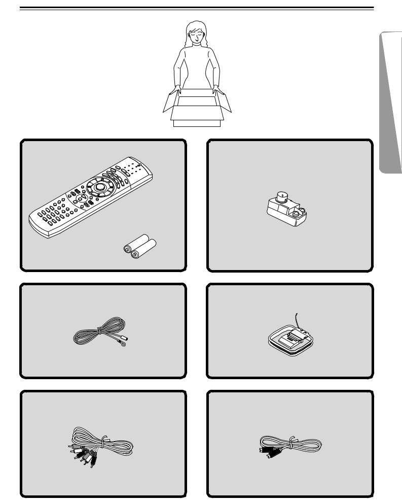
Supplied Accessories
Make sure your box contains everything listed below. If any pieces are missing, contact your nearest Onkyo dealer.
The number of accessories is indicated in brackets.
Remote controller (RC-437M) [1] |
FM outdoor antenna (aerial) adapter [1] |
Batteries (size AA/R6/UM3) [2]
FM antenna (aerial) [1] |
AM loop antenna (aerial) [1] |
Audio/video connection cable [1] |
S video cable [1] |
7
Preparing the Remote Controller
Inserting the Batteries
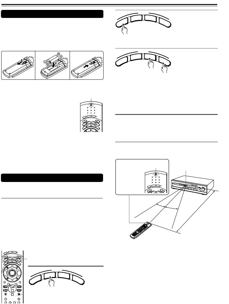
1 Detach the battery cover.
2Insert the two size AA/R6/UM3 batteries.
Be sure to match the + and – ends of the batteries with the diagram inside the battery compartment.
3 Attach the battery cover.
1 |
2 |
3 |
Notes
• When the batteries are getting weak, the SEND/ |
SEND/LEARN |
|||||
LEARN indicator on the remote controller starts |
indicator |
|
|
|
||
flashing. In this case, replace the batteries with |
|
|
|
|
|
|
new ones. |
|
SEND |
LEARN |
|
|
|
|
|
|
|
|
|
|
For the other functions of this indicator, see |
|
|
|
|
|
|
“Pointing the remote controller in the right |
|
|
|
|
|
|
direction” on the right, and page 63. |
P |
ON |
STNBY |
|
|
|
LEE |
|
|
|
|
|
|
S |
|
|
|
|
|
|
|
|
S L |
|
|
|
|
• Do not mix new batteries with old batteries or |
|
INPUT |
E ECTOR |
|
|
|
|
MODE |
|
|
|
||
|
|
T |
|
|
|
|
different kinds of batteries. |
|
DVD |
A/MD |
TV |
||
UDIO |
ENING MODE |
|||||
A IST |
T – D |
|
|
|||
L |
STEREO |
A. |
|
|||
|
R |
|
|
|
|
|
|
R |
|
|
|
C |
|
• To avoid corrosion, remove the batteries if the |
U |
|
|
|
|
TR |
S |
|
|
|
|
L |
|
|
E |
M |
ENU |
|
|
|
|
TITL |
|
|
|
||
remote controller is not to be used for a long time.
• Remove dead batteries immediately to avoid damage from corrosion. If the remote controller does not operate smoothly, replace both batteries at the same time.
• The life of the supplied batteries is about six months but this varies depending on usage.
Using the Remote Controller
 Switching the remote controller function modes
Some buttons on the remote controller have two or more functions. To set the functionality of these buttons, press one of the four MODE (AUDIO, DVD, TA/MD, TV) buttons in advance.
The function mode remains the same until another MODE button is pressed.
(Details about the functions and the related function modes are explained in each section.)
EEP |
ON |
STNBY |
|
|
|
|
|
|
||
|
|
|
|
|
|
|
|
|
|
|
SL |
|
|
|
|
|
|
|
|
|
|
|
INPUT SELECTOR |
|
|
|
|
|
|
|||
UDI |
|
MODE |
|
TV |
MODE buttons |
|
|
|||
ENING MODE |
|
|
|
|||||||
O |
DVD |
TA/MD |
|
|
|
|
|
|
||
A IST |
|
|
|
|
|
|
|
|
|
|
L |
STEREO T – D |
A. |
|
|
|
|
|
|||
R |
|
|
|
|
|
|
|
|
|
|
R |
|
|
|
|
C |
|
|
|
|
|
U |
|
|
|
|
|
TR |
|
|
|
|
S |
|
|
|
|
|
L |
|
|
|
|
|
|
LE |
ME |
NU |
|
|
|
|
|
|
|
TIT |
|
|
|
|
|
|
|
||
|
|
|
|
|
|
|
|
MODE |
|
|
CH |
|
ENTER |
|
VOL |
|
|
TA/ |
|
||
TUN |
|
|
|
|
|
|
|
D |
M |
|
|
|
|
|
|
|
|
|
|||
|
|
|
|
|
|
|
V |
|
||
|
|
|
|
|
|
|
D |
|
|
D |
|
RET |
|
|
UP |
|
|
IO |
|
|
T |
|
URN |
SET R |
|
|
|
|
||||
|
|
/VC |
|
|
U |
|
|
|||
REPEAT |
|
|
TV |
|
MUTING |
D |
|
|
V |
|
|
A – B |
DIMMER |
|
A |
|
|
|
|||
REC |
|
|
|
OPEN/CLOSE |
Press MODE DVD first before operating |
|||||
RANDOM |
|
|
|
SLOW |
the built-in DVD player. |
|||||
SUBTITLE – ON / OFF ANGLE |
ZOOM |
|
|
|
|
|||||
|
MODE |
|
|
|
D |
TA/ |
M |
V |
|
||
D |
|
|
D |
O |
|
|
T |
A |
|
|
V |
Press MODE AUDIO first before operating the speaker setting and sound related operations.
|
MODE |
|
|
|
D |
TA/ |
M |
V |
|
||
D |
|
|
D |
IO
D
U
A
Press MODE TA/MD first before operating the Onkyo MD recorder or z-connected cassette tape deck (see pages 12 and 31).
Press MODE TV first before operating your TV.
To operate the TV with the supplied remote controller, you need to let the remote controller learn the TV remote control signals (see pages 31 and 63).
 Pointing the remote controller in the right direction
Point the remote controller toward the remote control sensor.
This indicator is SEND/LEARN
lit while any |
indicator |
Remote control sensor |
|||||
|
|
||||||
button on the |
|
|
|||||
|
|
|
|
|
|
|
|
remote controller |
SEND |
LEARN |
|
|
|
|
|
|
|
|
|
|
|
|
|
is pressed. |
|
|
|
|
|
|
|
|
ON |
STNBY |
|
|
|
|
|
|
EEP |
|
|
|
|
|
|
|
SL |
|
|
|
|
|
|
|
INPUT SE LECTOR |
|
|
|
|
|
|
|
MODE |
|
|
|
|
|
|
|
DVD |
TA/MD |
|
|
|
|
|
|
|
|
|
|
|
|
eet) |
|
|
30˚ |
|
|
|
(16 |
f |
|
|
30˚ |
|
|
m |
|
|
|
|
|
|
5 |
|
|
|
|
|
|
About |
|
|
|
|
|
|
|
|
|
|
|
|
Notes
•Place the unit away from strong light such as direct sunlight or inverted fluorescent light which can prevent proper operation of the remote controller.
•Using another remote controller of the same type in the same room or using the unit near equipment which uses infrared rays may cause operational interference.
•Do not put any object (such as a book) on the remote controller. The buttons of the remote controller may be pressed by mistake and drain the batteries.
•Make sure the audio rack doors do not have colored glass. Placing the unit behind such doors may prevent proper remote controller operation.
•If there is any obstacle between the remote controller and the
remote control sensor, the remote controller will not operate.
8
Notes on Discs
This section shows you how to handle, clean, and store discs.
Playable Discs
This DVD Receiver can playback the following discs.
|
Disc mark |
Contents |
Disc |
Maximum |
|||
|
size |
playback time |
|||||
|
|
|
|
|
|
||
|
|
|
|
|
|
|
|
|
|
|
|
|
|
|
Approx. 4 hours |
|
|
|
|
|
Audio |
12 cm |
(single sided disc) |
|
|
|
|
|
Approx. 8 hours |
||
|
|
|
|
|
+ |
|
|
DVD |
|
|
|
|
|
(double sided disc) |
|
|
|
|
|
Video |
|
||
videos |
|
|
|
|
|
Approx. 80 minutes |
|
|
|
|
|
(moving |
|
||
|
|
|
|
|
8 cm |
(single sided disc) |
|
|
|
|
|
|
|||
|
|
|
|
|
pictures) |
|
|
|
|
|
|
|
Approx. 160 minutes |
||
|
|
|
|
|
|
||
|
|
|
|
|
|
|
(double sided disc) |
|
|
|
|
|
|
|
|
VIDEO |
|
|
|
|
Audio + |
12 cm |
Approx. 74 minutes |
|
|
|
|
Video |
|
|
|
CDs |
|
|
|
|
(moving |
8 cm |
Approx. 20 minutes |
|
|
|
|
|
pictures) |
||
|
|
|
|
|
|
|
|
Audio |
|
|
|
|
|
12 cm |
Approx. 74 minutes |
|
|
|
|
Audio |
|
|
|
|
|
|
|
8 cm (CD |
|
||
CDs* |
|
|
|
|
Approx. 20 minutes |
||
|
|
|
|
|
|||
|
|
|
|
|
|
single) |
|
|
|
|
|
|
|
|
|
|
|
|
|
|
|
|
|
*Finalized CD-Rs are also playable.
Such CD-Rs that TOC (Table of Contents) information (such as truck numbers) are recorded on to the PMA –– a special area in the disc is described as finalized CD-Rs.
•You cannot playback discs other than those listed above.
•You cannot play discs such as CD-RW, CD-ROM, DVDRAM, DVD-RW, etc., even if the marks in the above table are labeled on those discs.
•This DVD Receiver uses the PAL/NTSC color system, and cannot playback DVD videos recorded in any other color system (SECAM, etc.).
•Avoid using heart-shaped or octagonal discs. Playing irregularly shaped discs may damage the internal mechanism of the DVD Receiver.
•Do not use discs that have residue from adhesive tape, rental discs that have peeling labels, or discs that have custom labels or stickers. Otherwise, you may not be able to eject the discs or the DVD Receiver may become inoperative.
Cleaning Discs
•Fingerprints and dust on the disc cause picture and sound deterioration. Wipe the disc from the center outwards with a soft cloth. Always keep the disc clean.
•If you cannot wipe off the dust with a soft cloth, wipe the disc lightly with a slightly moistened soft cloth and finish with a dry cloth.
•Do not use any type of solvent such as thinner, benzine, commercially available cleaners or antistatic spray for vinyl LPs. It may damage the disc.
Storing Discs
•Do not store discs in a place subject to direct sunlight or near heat sources.
•Do not store discs in places subject to moisture and dust such as a bathroom or near a humidifier.
•Store discs vertically in a case. Stacking or placing objects on discs outside of their case may cause warping.
About VIDEO CDs
This DVD Receiver supports VIDEO CDs equipped with the PBC (Version 2.0) function. (PBC is the abbreviation for Playback Control.)
You can enjoy two playback variations depending on the type of disc.
•VIDEO CD not equipped with PBC function (Version 1.1)
Sound and movies can be played on this DVD Receiver in the same way as an audio CD.
•VIDEO CD equipped with PBC function (Version 2.0)
In addition to operation of a VIDEO CD not equipped with the PBC function, you can enjoy playback with interactive software and search function using the menu displayed on the TV screen (Menu Playback). Some of the functions described in this Instruction Manual may not work with some discs.
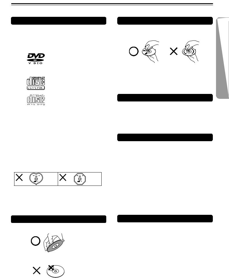
Handling Discs
• Do not touch the playback side of the disc.
 Playback side
• Do not attach paper or tape to discs.
Notes on Copyright
It is forbidden by law to copy, broadcast, show, broadcast on cable, play in public, and rent copyrighted material without permission.
DVD videos are copy protected, and any recordings made from these discs will be distorted.
This product incorporates copyright protection technology that is protected by method claims of certain U.S. patents and other intellectual property rights owned by Macrovision Corporation and other rights owners. Use of this copyright protection technology must be authorized by Macrovision Corporation, and is intended for home and other limited viewing uses only unless otherwise authorized by Macrovision Corporation. Reverse engineering or disassembly is prohibited.
9
Connecting to a TV
Before connecting
•Refer also to the instruction manual of the TV.
•When you connect the DVD Receiver to the TV, be sure to turn off the power and unplug both the units from the mains before making any connections.
•Connect the DVD Receiver to the TV directly. If you connect the DVD
Receiver to a VCR, TV/VCR combination, or video selector, the playback picture may be distorted as DVD videos are copy protected.
•Connect the plugs securely.
•Note that one audio/video connection cable and one S video connection cable are supplied.
Incomplete
 Insert completely
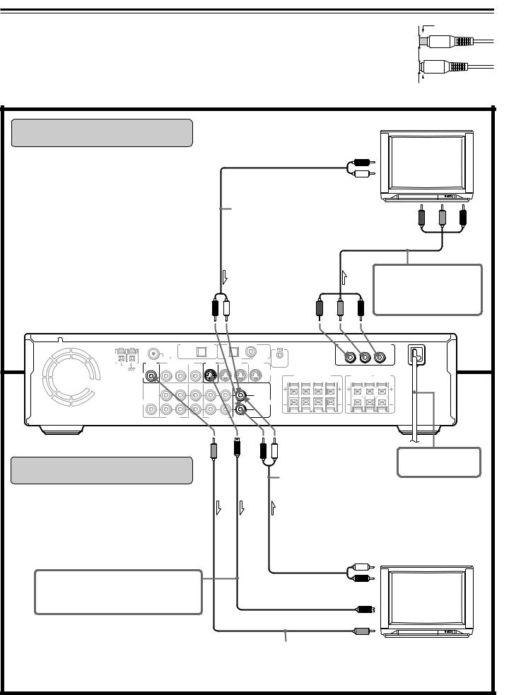
Connecting to a TV With Component Video Inputs
If the TV or monitor has component video inputs, make this connection. Connecting to these inputs allows you to enjoy higher quality picture playback compared to the connections explained in “Connecting to a TV Without Component Video Inputs” below.
Notes
•Actual labels for component video inputs may vary depending on the TV manufacturer (ex. Y/CB/CR, Y/ B-Y/R-Y, etc.).
•In some TVs, the color levels of the playback picture may be reduced slightly or the tint may change. In such a case, adjust the TV for optimum performance.
|
|
TV |
|
|
To audio outputs |
|
|
|
R (Red) |
|
|
|
L (White) |
|
|
Stereo audio connection cable |
To component |
|
|
|
video inputs Y |
PB |
PR |
Component video connection cable
|
|
Only pictures from a DVD video or |
|
(Red) |
(White) |
VIDEO CD played with the DVD |
|
Receiver will be output to the TV. |
|||
|
|
ANTENNA |
DIGITAL OUTPUT |
DIGITAL INPUT |
COMPONENT VIDEO OUTPUT |
|
|
|
|
(OPT) |
|
(OPT) |
|
(COAX) |
|
|
|
|
|
|
|
|
|
FM 75 |
|
|
|
VIDEO 1 |
VIDEO 2 |
REMOTE |
|
|
|
|
|
|
|
|
MON |
1 – VIDEO – 2 |
MON |
VIDEO 1 |
VIDEO 2 |
|
|
|
|
|
|
||||
AM |
CONTROL |
|
|
|
|
|
|
||||||||
OUT |
OUT |
IN |
IN |
OUT |
OUT |
IN |
IN |
|
|
|
|
|
|
|
|
|
|
|
|
|
|
|
|
||||||||
|
|
|
|
|
|
|
|
S VIDEO |
|
|
|
SURROUND |
CENTER |
||
|
VIDEO |
|
|
|
|
|
|
|
FRONT SPEAKERS |
||||||
|
|
|
|
|
|
|
|
SPEAKERS |
SPEAKER |
||||||
|
|
|
|
|
|
|
|
|
R |
A |
L |
R B L |
|||
|
|
|
|
|
|
|
|
|
R |
L |
|
||||
|
|
OUT |
IN |
IN |
OUT |
IN |
|
|
|
|
|
|
|
|
|
|
SUB |
|
|
|
(REC) |
(PLAY) |
|
|
|
|
|
|
|
|
|
|
|
|
|
|
|
|
|
|
|
|
|
|
|
|
|
|
WOOFER |
|
|
|
|
|
|
L |
|
|
|
|
|
|
|
|
PRE OUT |
|
|
|
|
|
|
|
|
|
|
|
|
|
|
AUDIO |
|
|
AUDIO |
|
|
|
R |
VIDEO |
VIDEO |
TAPE/MD |
TV/LINE |
1 |
2 |
|
|
Connecting to a TV Without
Component Video Inputs
If the TV or monitor has an S video input, make the S video connection. The S video connection will provide higher quality picture playback.
(Yellow) |
(Red) |
(White) |
Stereo audio connection cable
DO NOT connect the power cord (mains lead) at this time.
S video connection cable
Both the S video and video connections are necessary, otherwise the picture from equipment to be connected on the next page may not be output to the TV.
To audio outputs
L (White) TV
R (Red)
To S video input
To video input
(Yellow)
Video connection cable
 : Signal flow
10

Connecting to Audio/Video Equipment
Before connecting
•Refer also to the instruction manual of each component to be connected.
•When you connect the DVD Receiver to audio/video equipment, be sure to turn off the power and unplug all the units from the mains before making any connections.
•About the DIGITAL INPUT (OPT) and DIGITAL
OUTPUT (OPT) connectors
Remove the protective caps before making connections.
When not in use, be sure to replace them.
•About the VIDEO 1 and VIDEO 2 jacks/connectors
The video input/output connections are also necessary even if you
make the S video input/output connections. |
|
|
|
|
|
|
|
|
|
|
|
|
|
||
• Connect the plugs securely. |
|
|
|
|
Incomplete |
||||||||||
• Note that one audio/video connection cable |
|
|
|
|
|
|
|
|
|
|
|
|
|
|
|
and one S video connection cable are |
|
|
|
|
|
|
|
|
|
|
|
|
|
|
|
supplied (if not used in the connection on |
|
|
|
|
|
|
|
|
|
|
|
|
|
|
|
the opposite page). |
|
|
|
|
|
|
|
|
|
|
|
|
|
|
|
|
|
|
|
|
Insert completely |
||||||||||
|
|
|
|
|
|||||||||||
|
|
|
|
|
|||||||||||
VCR, DVD Recorder, etc. |
|
Set Top Box, LD Player, |
|
Video Cassette Player, etc. |
|
|
|
|
|
|
|
(Red)R |
(White)L |
To audio inputs
Audio/video connection cable
(Red) |
(White) |
(Yellow) |
(Yellow) |
input To video |
output To video |
(Yellow) |
(Yellow) |
(White)L |
(Red)R |
To audio outputs
(White) |
(Red) |
digital Tooutput audio optical
video S To input
DIGITAL OUTPUT |
DIGITAL INPUT |
(OPT) |
(OPT) |
(COAX) |
|
|
|
|
|
VIDEO 1 |
VIDEO 2 |
|
MON |
1 – VIDEO – 2 |
|
MON |
VIDEO 1 |
VIDEO 2 |
||
OUT |
OUT |
IN |
IN |
OUT |
OUT |
IN |
IN |
S VIDEO
VIDEO
OUT |
IN |
IN |
OUT |
IN |
IN |
SUB |
|
|
(REC) |
(PLAY) |
|
|
|
|
|
|
|
WOOFER |
|
|
|
|
L |
PRE OUT |
|
|
|
|
|
AUDIO |
|
|
|
|
AUDIO |
|
|
|
|
|
R |
VIDEO |
VIDEO |
TAPE/MD |
TV/LINE |
||
|
1 |
2 |
|
|
|
videoSTo output |
To audio |
(Red)R |
|
(Yellow) |
audiooutput Todigital coaxial |
output |
|
outputs |
|
(White)L |
output videoTo |
S video videoSTo |
|
|
cable |
|||||
|
Audio/video |
|
|
|
|
|
S video connection cable |
connection |
|
|
|
|
|
|
|
|
|
|
|
|
Optical fiber cable |
|
|
|
|
|
connection |
|
|
|
|
|
|
cable |
This connection is only for equipment with a digital optical/coaxial audio output.
Digital recording is not always possible; therefore, also connect to the analog audio jacks (see page 61 for recording sound).
To VIDEO 1
To VIDEO 2
|
|
|
Coaxial |
|
|
|
connection |
(Red) |
(White) |
(Yellow) |
cable |
|
|||
|
|
DIGITAL OUTPUT |
DIGITAL INPUT |
(OPT) |
(OPT) |
(COAX) |
|
|
|
|
|
VIDEO 1 |
VIDEO 2 |
|
MON |
1 – VIDEO – 2 |
|
MON |
VIDEO 1 |
VIDEO 2 |
||
OUT |
OUT |
IN |
IN |
OUT |
OUT |
IN |
IN |
S VIDEO
VIDEO
OUT |
IN |
IN |
OUT |
IN |
IN |
SUB |
|
|
(REC) |
(PLAY) |
|
|
|
|
|
|
|
WOOFER |
|
|
|
|
L |
PRE OUT |
|
|
|
|
|
AUDIO |
|
|
|
|
AUDIO |
|
|
|
|
|
R |
VIDEO |
VIDEO |
TAPE/MD |
TV/LINE |
||
|
1 |
2 |
|
|
|
|
ANTENNA |
|
AM |
MON |
|
OUT |
||
|
|
DIGITAL OUTPUT |
DIGITAL INPUT |
COMPONENT VIDEO OUTPUT |
||||||
|
|
(OPT) |
|
(OPT) |
|
(COAX) |
Y |
PB |
PR |
|
|
|
|
|
|
|
|||
FM 75 |
|
|
|
VIDEO 1 |
VIDEO 2 |
REMOTE |
|
|
|
1 – VIDEO – 2 |
MON |
VIDEO 1 |
VIDEO 2 |
CONTROL |
|
|
|||
OUT |
IN |
IN |
OUT |
OUT |
IN |
IN |
|
|
|
To TAPE/MD
|
|
|
|
S VIDEO |
|
SURROUND |
CENTER |
|
VIDEO |
|
|
|
FRONT SPEAKERS |
||||
|
|
|
SPEAKERS |
SPEAKER |
||||
|
|
|
|
R A L |
R B L |
|||
|
|
|
|
R |
L |
|
||
OUT IN |
IN |
OUT |
IN |
IN |
|
|
|
|
SUB |
|
(REC) |
(PLAY) |
|
|
|
|
|
|
|
|
|
|
|
|
|
|
WOOFER |
|
|
|
L |
|
|
|
|
PRE OUT |
|
|
|
|
|
|
DO NOT connect the |
|
AUDIO |
|
|
|
AUDIO |
|
|
|
|
|
|
|
|
|
|
power cord (mains lead) |
||
|
|
|
|
R |
|
|
|
|
|
|
|
|
|
|
|
at this time. |
|
VIDEO |
VIDEO |
TAPE/MD |
TV/LINE |
|
|
|
||
|
|
|
|
|||||
1 |
2 |
|
|
|
|
|
|
|
Optical fiber cable
DIGITAL OUTPUT |
DIGITAL INPUT |
(OPT) |
(OPT) |
(COAX) |
|
|
|
|
|
VIDEO 1 |
VIDEO 2 |
|
MON |
1 – VIDEO – 2 |
|
MON |
VIDEO 1 |
VIDEO 2 |
||
OUT |
OUT |
IN |
IN |
OUT |
OUT |
IN |
IN |
S VIDEO
VIDEO
OUT |
IN |
IN |
OUT |
IN |
IN |
SUB |
|
|
(REC) |
(PLAY) |
|
|
|
|
|
|
|
WOOFER |
|
|
|
|
L |
PRE OUT |
|
|
|
|
|
AUDIO |
|
|
|
|
AUDIO |
|
|
|
|
|
R |
VIDEO |
VIDEO |
TAPE/MD |
TV/LINE |
||
|
1 |
2 |
|
|
|
(White) |
(Red) |
(White)
(Red)
This connection is only for equipment with a digital optical audio input.
Digital recording is not always possible; therefore, also connect to the analog audio jacks (see page 61 for recording sound).
To digital optical audio input
To audio outputs (PLAY)
L (White)
R (Red)
Stereo audio connection cable
MD Recorder, DAT,
Cassette Tape Deck,
CD Recorder, etc.
R |
L |
To audio |
|
inputs (REC) |
|||
(Red) |
(White) |
||
|
 : Signal flow
11
zConnection for the Onkyo CassetteTape Deck
The supplied remote controller has the following three extended functions in addition to operating the DVD Receiver:
•First, operating the TV (see page 31),
•Second, operating the Onkyo MD recorder (no zconnection is needed) (see page 31), and
•Third, operating the zconnected Onkyo cassette tape deck through the DVD Receiver (see page 31).
To use the third function, you need to make the zconnection between the cassette tape deck and the DVD Receiver. The z cable to make the zconnection is supplied with the cassette tape deck.
If you start playing back the cassette tape deck after making the zconnection, the DVD Receiver automatically changes its input source to the cassette tape deck –– Direct Change function.
Onkyo cassette tape deck
|
REMOTE |
zcable |
CONTROL |
|
|
ANTENNA |
AM |
MON |
OUT |
|
|
VIDEO |
|
SUB |
|
WOOFER |
|
PRE OUT |
AUDIO
DIGITAL OUTPUT |
DIGITAL INPUT |
COMPONENT VIDEO OUTPUT |
(OPT) |
(OPT) |
(COAX) |
Y |
PB |
PR |
FM 75 |
|
|
MON |
VIDEO 1 |
VIDEO 2 |
REMOTE |
|
1 – VIDEO – 2 |
|
VIDEO 1 |
VIDEO 2 |
CONTROL |
|||
OUT |
IN |
IN |
OUT |
OUT |
IN |
IN |
|
|
|
|
|
|
S VIDEO |
|
|
|
|
SURROUND |
CENTER |
|
|
|
|
|
|
FRONT SPEAKERS |
L |
SPEAKERS |
SPEAKER |
||||
|
|
|
|
|
R |
A |
L |
R B |
R |
L |
|
|
OUT |
IN |
IN |
OUT |
IN |
IN |
|
|
|
|
|
|
|
|
|
|
(REC) |
(PLAY) |
|
|
|
|
|
|
|
|
|
|
|
|
|
L |
|
|
|
|
|
|
|
AUDIO
VIDEO VIDEO TAPE/MD TV/LINE R DO NOT
NOT connect the
1 2
power cord (mains lead) at this time. 
Notes
•Connect the plugs securely.
•Be sure to connect to the zconnectors using the zcable.
•The connections on page 11 are needed even if zconnection is made.
•Do not connect the DVD Receiver’s zconnector to any component other than an Onkyo product. It may cause malfunction.
Positioning Speakers
 Incomplete
 Insert completely
Two speaker systems (SPEAKERS A and SPEAKERS B) can be connected to the DVD Receiver.
The SPEAKERS A system is to be placed in the main room, and the SPEAKERS B system is to be placed in a second room.
The configuration of the SPEAKERS A system
The SPEAKERS A system consists of the front left, center, and right speakers, surround left and right speakers, and subwoofer.
You can reproduce the sounds such as Dolby surround and DTS surround.
The configuration of the SPEAKERS B system
The SPEAKERS B system consists of the front left and right speakers.
You can reproduce only monaural and stereo sounds.
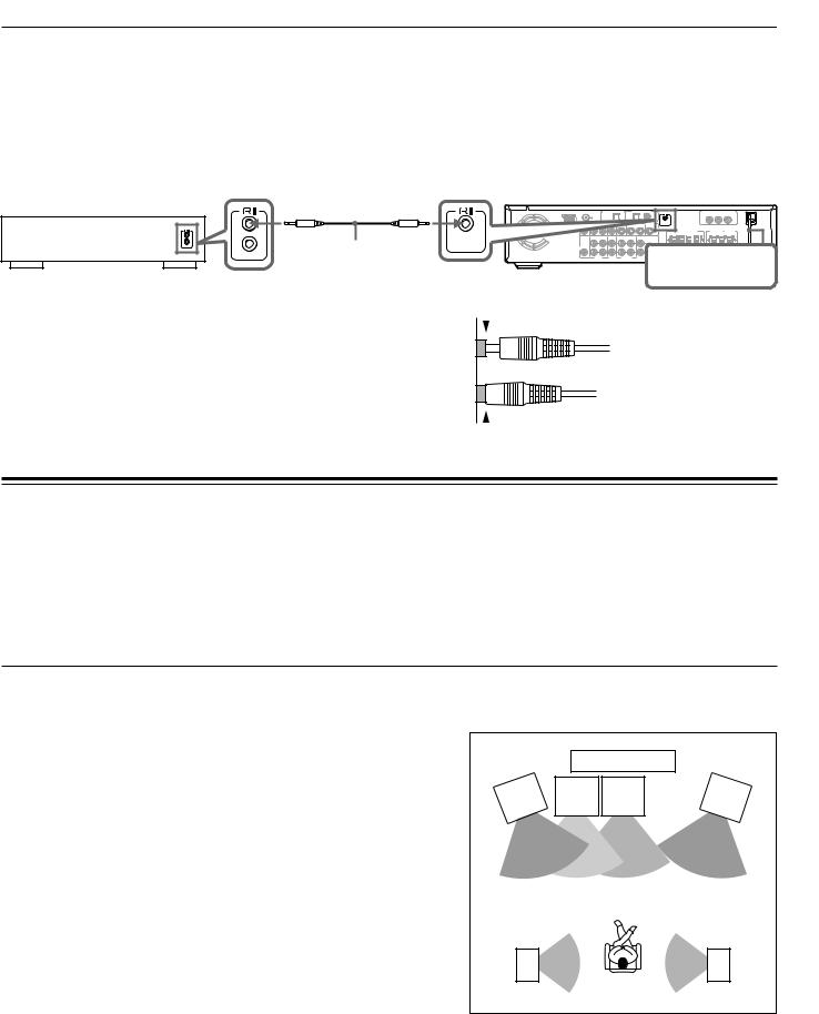
 Standard speaker placement of the SPEAKERS A system
Speaker placement plays an important role in the reproduction of Surround sound. The placement of the speakers varies depending on the size of the room and the wall coverings used in the room. The illustration below shows an example of a layout for standard speaker placement. Refer to this example when you position the speakers in order to experience the best of Surround sound.
For ideal Surround effects, all speakers should be installed.
If a center speaker or subwoofer is not connected, the sound from the unused channel is distributed to the connected speakers in order to reproduce the best Surround sound possible.
Front
The center speaker reproduces a richer sound image by enhancing the perception of the sound's source and movement.
The left, right, and center speakers should face the seated listener and be placed at ear level.
Surround
The surround speakers reproduce the feel of a moving sound while creating the sensation of being in the middle of the action.
Place the left and right surround speakers 1 meter (3 feet) above the listener's ear level and facing toward the sides of the room, making sure that the listener is within the speakers' dispersion angle.
Subwoofer
Install a subwoofer with a built-in power amplifier for powerful bass sounds.
|
|
|
TV |
|
Front |
|
Sub- |
Front |
Front |
left |
er |
woofer |
Center |
right |
|
Speaker |
Speaker |
||
Speak |
|
|||
Surround |
|
|
Surround |
|
left |
|
|
right |
|
Speaker |
|
|
Speaker |
|
The placement of the subwoofer does not affect the final quality of the sound image much, therefore, you can install it wherever it is convenient.
Refer to the speakers’ instruction manuals for details.
12
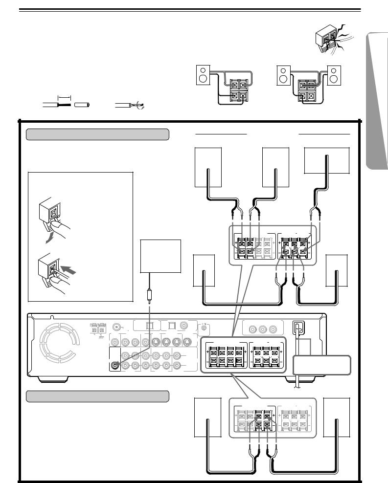
Connecting Speakers
Before connecting
•Refer also to the instruction manuals of the speakers.
•This DVD Receiver is designed to reproduce optimum sound quality when speakers with the impedances specified below are connected.
Please check the following information and choose speakers with appropriate impedances for the connections.
Front speakers: 6 ohms min. per speaker Center speaker: 6 ohms min.
Surround Speakers : 6 ohms min. per speaker
•Strip 10 mm from the end of each cord, then twist the exposed wires tightly.
10
mm
• To prevent damage to circuits, never short-circuit the positive (+) and negative (–) speaker wires.
• Do not connect the speaker cable to the L and R
connectors at the same time and do not connect |
NO! |
|||
more than one speaker to the same speaker |
||||
|
||||
connectors. |
|
|
|
|
|
R L |
R L |
|
|
+ |
|
+ |
|
|
– |
NO! |
– |
NO! |
|
|
|
|||
Connecting to SPEAKERS A |
|
|
|
Front speakers |
|
|
||
|
|
Right ch. |
|
Left ch. |
|
Center ch. |
||
The main speaker system is SPEAKERS A. |
|
|
|
|
|
|
|
|
Follow the illustration on the right. |
|
|
|
|
|
|
|
|
How to connect to the speaker |
|
|
|
|
|
|
|
– + |
connectors |
|
– |
+ |
|
– |
+ |
|
|
|
|
|
|
|
||||
Press and hold |
|
|
|
|
|
|
|
|
the lever. |
|
|
|
|
|
|
|
|
|
|
Surround |
R A L |
R B L |
SURROUND |
CENTER |
Surround |
|
|
|
R L |
|
|||||
|
|
|
|
FRONT SPEAKERS |
SPEAKERS |
SPEAKER |
|
|
|
|
|
|
|
|
|
||
|
|
speaker |
|
|
|
|
speaker |
|
|
Active |
Right ch. |
|
|
|
|
Left ch. |
|
Insert the stripped |
subwoofer |
|
|
|
|
|
|
|
end of the cord. |
|
|
|
|
|
|
|
|
By releasing the |
|
|
|
|
|
|
|
|
lever, the lever is |
|
|
|
|
|
|
|
|
replaced. |
|
– |
+ |
|
|
|
|
– + |
|
|
|
|
|
|
|||
ANTENNA |
DIGITAL OUTPUT |
DIGITAL INPUT |
|
|
|
|
(OPT) |
|
(OPT) |
|
(COAX) |
|
|
|
FM 75 |
|
|
|
VIDEO 1 |
VIDEO 2 |
REMOTE |
|
AM |
MON |
1 – VIDEO – 2 |
MON |
VIDEO 1 |
VIDEO 2 |
CONTROL |
|||
OUT |
OUT |
IN |
IN |
OUT |
OUT |
IN |
IN |
|
|
|
|
||||||||
|
|
|
|
|
|
|
|
S VIDEO |
|
VIDEO
OUT |
IN |
IN |
OUT |
IN |
IN |
SUB |
|
|
(REC) |
(PLAY) |
|
|
|
|
|
|
|
WOOFER |
|
|
|
|
L |
PRE OUT |
|
|
|
|
|
AUDIO |
|
|
|
|
AUDIO |
|
|
|
|
|
R |
VIDEO |
VIDEO |
TAPE/MD |
TV/LINE |
||
|
1 |
2 |
|
|
|
|
COMPONENT VIDEO OUTPUT |
|||
|
Y |
|
PB |
PR |
FRONT SPEAKERS |
SURROUND |
CENTER |
||
R A L |
R B L |
SPEAKERS |
SPEAKER |
|
R |
L |
|
||
DO NOT connect the power cord (mains lead) at this time.
|
Front speaker |
Front speaker |
Connecting to SPEAKERS B |
Right ch. |
Left ch. |
|
|
|
|
FRONT SPEAKERS |
SURROUND CENTER |
|
SPEAKERS SPEAKER |
|
|
R A L R B L |
|
To place the additional speaker system for the second |
R L |
|
|
|
|
room, make the SPEAKERS B connection on the right. |
|
|
|
– + |
– + |
13
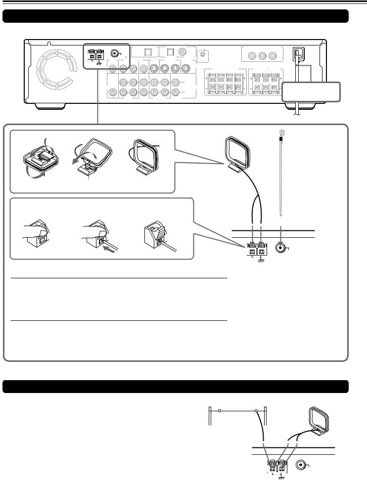
Making Antenna (Aerial) Connections
Connecting the Supplied FM and AM Indoor Antennas (Aerials)
ANTENNA |
DIGITAL OUTPUT |
DIGITAL INPUT |
|
|
|
|
(OPT) |
|
(OPT) |
|
(COAX) |
|
|
|
FM 75 |
|
|
|
VIDEO 1 |
VIDEO 2 |
REMOTE |
|
|
MON |
1 – VIDEO – 2 |
MON |
VIDEO 1 |
VIDEO 2 |
||||
AM |
CONTROL |
||||||||
OUT |
OUT |
IN |
IN |
OUT |
OUT |
IN |
IN |
|
|
|
|
||||||||
|
|
|
|
|
|
|
|
S VIDEO |
|
VIDEO
OUT |
IN |
IN |
OUT |
IN |
IN |
SUB |
|
|
(REC) |
(PLAY) |
|
|
|
|
|
|
|
WOOFER |
|
|
|
|
L |
PRE OUT |
|
|
|
|
|
AUDIO |
|
|
|
|
AUDIO |
|
|
|
|
|
R |
VIDEO |
VIDEO |
TAPE/MD |
TV/LINE |
||
|
1 |
2 |
|
|
|
|
COMPONENT VIDEO OUTPUT |
||||
|
Y |
|
PB |
PR |
|
FRONT SPEAKERS |
SURROUND |
CENTER |
|||
SPEAKERS |
SPEAKER |
||||
R A L |
R B L |
||||
R |
L |
|
|||
DO NOT connect the power cord (mains lead) at this time.
AM indoor antenna (aerial) |
FM indoor antenna |
|
(aerial) |
|
|
|
Insert into the hole. |
|
|
|
|
||
Press up and |
Insert the end of |
Release the lever to |
|
||||||
hold the lever. |
the cord. |
secure the connection. |
|
||||||
|
|
|
|
|
|
|
|
|
|
 Adjusting the position of the FM indoor antenna (aerial)
While listening to an FM program (see page 28), extend the antenna (aerial) and move it in various directions until the clearest signal is received, then secure the antenna (aerial) with push pins in the position with the least distortion.
 Adjusting the position of the AM indoor antenna (aerial)
While listening to an AM program (see page 28), set the antenna (aerial) in the direction and position where you receive the clearest sound.
Put it as far away as possible from the unit, TVs, speaker cables, and power cords (mains leads).
ANTENNA
FM 75
AM
Note
Insert one end of the AM antenna (aerial) cord to either of the AM antenna (aerial) connectors and the other end to the other connector. There is no difference between one end of the AM antenna (aerial) cord and the other end unlike the speaker cords which have positive and negative poles.
Connecting an AM Outdoor Antenna (Aerial)
An outdoor antenna (aerial) will be more effective if it is stretched |
Outdoor antenna (aerial) |
AM indoor antenna (aerial) |
horizontally above a window or outside. |
|
|
Leave the supplied AM indoor antenna (aerial) connected. |
|
|
Note
To avoid the risk of lightning and electrical shock, grounding is necessary. Follow item 19 of the "Important Safeguards" on page 2 when you install an outdoor antenna (aerial).
ANTENNA
FM 75
AM
14
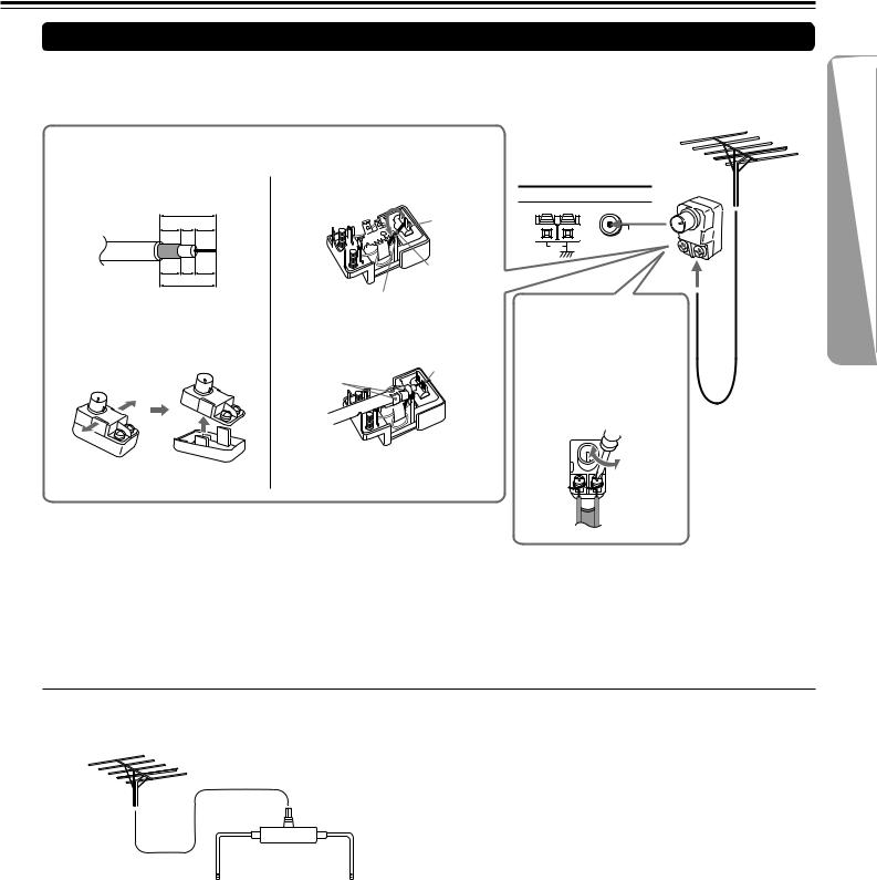
Connecting an FM Outdoor Antenna (Aerial)
If the FM reception is not very clear with the supplied antenna (aerial), connect an FM outdoor antenna (aerial) instead of the indoor FM antenna (aerial).
Connecting coaxial cable to a 75/300 ohm antenna (aerial) adapter
1 Strip the end of the coaxial cable.
15 mm
6 3 6
mm mm mm
1/4 |
1/8 |
1/4 |
in. in. in.
5/8 in.
2With your fingernail or a small screwdriver, press the stoppers outward and remove the cover.
3Remove the transformer wire A from slit B and insert it into slit C.
Slit B
Wire A
Slit C
4 Insert the end of the cable.
5 Clamp it in place with pliers.
4
5
6 Reinstall the cover.
Notes
FM outdoor antenna (aerial)
ANTENNA
FM 75
AM
Connecting 300 ohm ribbon wire to a supplied 75/300 ohm antenna (aerial) adapter
Loosen the screws and wrap the wire around these screws. Then tighten the screws with a screwdriver.
Tighten
Loosen
•Install the antenna (aerial) well away from tall buildings and in an area where FM stations can directly be received.
•Keep the antenna (aerial) away from noise sources (neon signs, busy roads, etc.).
•It is dangerous to put the antenna (aerial) close to power lines. Keep it well away from power lines, transformers, etc.
•To avoid the risk of lightning and electrical shock, grounding is necessary. Follow item 19 of the "Important Safeguards" on page 2 when you install the outdoor antenna (aerial).
 Directional Iinkage
Do not use the same antenna (aerial) for both FM and TV (or VCR) reception since the FM and TV (or VCR) signals can interfere with each other. If you must use a common FM/TV (or VCR) antenna (aerial), use a directional linkage type splitter.
Directional linkage type splitter
To DVD Receiver |
To TV (or VCR) |
15
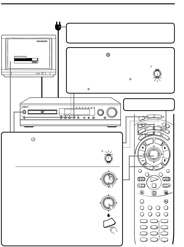
Connecting the Power/Turning on the DVD Receiver
Before connecting
•Make sure that all the connections from pages 10 to 15 are complete (the connection to the TV is required).
•Turning on the DVD Receiver may cause a momentary power surge, which might interfere with other electrical equipment such as computers. If this happens, use a wall outlet on a different circuit.
|
|
|
|
1 Connect the power cord (mains lead) |
|||||||||||||||||
|
|
|
|
to a wall outlet (the mains). |
|
|
|
|
|
|
|
|
|||||||||
Thank you for your purchase of Our DVD-Video Player. |
2 Press the |
|
|
|
|
|
|
|
|
|
|
|
|
|
|
|
|
||||
Please make a selection |
|
|
|
|
|
|
|
|
|
|
|
|
|
|
|
|
|
||||
for On-Screen Language and your TV shape and |
POWER switch to |
|
|
|
|
|
|||||||||||||||
press ENTER button on your remote control. |
|
|
|
|
|
||||||||||||||||
|
FIRST SETUP |
|
|
|
|
|
|
||||||||||||||
|
TV Shape |
4:3LB |
|
switch on the main power. |
|
|
|
|
|
|
|
|
|
||||||||
|
On-Screen Language ENG |
|
|
|
|
|
|
|
|
|
|
|
|
|
|
|
|
|
|
|
|
|
|
|
|
The DVD Receiver enters standby mode. |
|
|
|
|
|
|
|
STANDBY/ON |
|
|
|||||||
|
|
|
|
The STANDBY indicator lights up in red. |
|
|
|
|
|
|
|
|
ON |
|
|
||||||
|
|
|
|
|
|
|
|
|
|
|
|
|
|
|
|
|
|
||||
|
|
|
|
Notes |
|
|
|
|
|
|
|
|
|
|
|
|
|
|
|
|
|
|
|
|
|
• To switch off the main power, press the POWER |
|
|
|
|
STANDBY |
|
|
||||||||||
|
|
|
|
switch again. |
|
|
|
|
|
|
|
|
|
|
|
|
|
|
|
|
|
|
|
|
|
• The buttons on the remote controller don’t operate if |
|
|
|
|
|
|
|
|
|
|
|
||||||
|
|
|
|
the POWER switch is set to OFF. |
|
|
|
|
|
|
|
|
|
|
|
|
|
|
|
||
|
|
|
|
|
|
|
Before operating the cursor |
|
|
||||||||||||
|
|
|
|
DVD/CD VIDEO 1 VIDEO 2 TV/LINE TAPE/MD FM AM |
|
VOLUME |
Press MODE DVD or MODE AUDIO. |
||||||||||||||
|
STANDBY/ON |
|
INPUT |
|
|
|
|
|
|
|
|
|
|
|
|
|
|
|
|
|
|
|
ON |
|
|
|
|
|
|
|
|
|
|
|
|
|
|
|
|
|
|
|
|
|
STANDBY |
|
|
|
|
|
|
|
|
|
|
|
|
|
|
|
|
|
|
|
|
|
|
|
|
|
ACOUSTIC |
|
|
|
|
|
|
|
|
N |
ST |
|
|
|
|||
|
|
|
|
|
|
|
|
|
|
|
|
|
|
|
|
|
|||||
|
POWER |
|
SURROUND STEREO Theater-Dimensional |
CONTROL |
|
|
|
|
|
|
|
O |
|
|
|
NBY |
|
|
|||
|
|
|
|
|
|
|
|
|
EP |
|
|
|
|
|
|
|
|
|
|
|
|
|
ON |
OFF |
|
TUNER PRESET |
|
|
S |
E |
|
|
|
|
|
|
|
|
|
|
|
|
|
|
|
|
|
L |
|
|
|
|
|
|
|
|
|
|
|
|
|
||||
|
|
|
|
|
|
|
|
|
|
|
|
|
|
UT |
SEL |
|
|
|
|
|
|
|
|
|
|
|
|
|
|
|
|
|
|
|
|
ECT |
OR |
|
|
||||
|
|
|
|
|
|
|
|
|
|
|
|
|
INP |
|
|
|
|
|
|
||
|
|
|
|
|
|
|
|
|
|
|
|
|
|
MODE |
|
|
|
|
|||
|
|
|
|
|
|
|
|
|
|
|
|
|
|
VD |
TA/ |
|
|
|
|||
|
|
|
|
|
|
|
|
|
|
IO |
|
|
D |
|
|
|
MD |
T |
|
||
|
|
|
|
|
|
|
|
|
|
|
|
ING |
MOD |
E |
|
V |
|||||
|
|
|
|
|
|
|
|
D |
|
|
|
|
|
|
|||||||
|
|
|
|
|
|
|
U |
|
|
EN |
|
|
|
|
|
|
|
|
|||
3 |
|
|
|
|
|
|
A |
|
|
T |
|
|
|
|
|
|
|
|
|
||
|
|
|
|
|
|
|
|
|
IS |
|
|
EO |
T |
|
|
|
|
||||
|
|
|
|
|
|
|
|
|
L |
|
|
|
– |
|
|
|
|||||
|
|
|
|
|
|
|
|
|
|
|
|
ER |
|
|
|
D |
|
|
|||
|
|
|
|
|
|
|
|
|
|
|
|
ST |
|
|
|
|
|
|
|
||
|
|
|
|
|
|
|
|
|
|
|
|
T |
|
|
|
|
|
U |
|
|
|
|
|
|
|
|
|
|
|
|
|
R |
|
|
|
|
|
|
|
|
A. |
|
|
|
Press |
STANDBY/ON on the DVD |
|
|
|
|
R |
|
|
|
|
|
|
|
|
|
C |
|
|||
|
|
|
|
|
|
|
|
|
|
|
|
|
|
T |
|||||||
|
|
|
|
U |
|
|
|
|
LE |
|
ME |
|
|
R |
|||||||
|
|
|
|
|
|
|
S |
|
|
|
|
|
|
|
|
|
|
|
|
L |
|
|
Receiver or ON on the remote controller. |
|
|
|
|
|
|
IT |
|
|
|
|
N |
|
|
||||||
|
|
|
|
|
|
|
|
|
|
|
|
|
|
|
|
||||||
The DVD Receiver turns on. |
STANDBY/ON |
The ON indicator lights up in orange. |
ON |
|
|
At the same time, the STANDBY indicator goes off. |
|
|
STANDBY |
The first time you turn on the DVD Receiver, the FIRST SETUP screen appears. In the FIRST SETUP screen, select the On-Screen Language and TV Shape according to the aspect ratio of the TV screen (see pages 54 and 55).
1Press  /
/ to select “On-Screen Language,” then press ENTER.
2Select a language with  /
/ , then press ENTER.
3Press  to select “TV Shape,” then press ENTER.
4Press  /
/ to select the aspect ratio of the TV screen, then press ENTER.
5Finally press SETUP.
All of your selections are set and the FIRST SETUP screen disappears.
Notes
•To turn off the DVD Receiver, press  STANDBY/ON on the DVD
Receiver, or STNBY  on the remote controller. The DVD Receiver enters standby mode. Be sure to set the volume to minimum before turning off the DVD Receiver.
•You can change the above settings later with “Customizing the Function Settings” on page 52.
 ENTER
ENTER
↔
 ENTER
ENTER
|
|
P |
|
|
U |
|
|
T |
|
R |
|
SE |
|
|
|
T |
|
|
|
CH |
|
|
|
|
ENTER |
|
|
|
VOL |
|
TUN |
|
|
|
|
|
|
|
|||
|
|
|
|
|
|
|
|
|
|
|
|
R |
|
|
|
|
|
|
P |
|
|
|
E |
|
|
|
|
U |
|
|
||
|
|
T |
|
|
ET |
|
R |
|
||
|
|
|
U |
RN |
S |
|
|
|
||
|
|
|
|
|
|
C |
|
|||
REPEAT |
|
|
|
|
/V |
|
MUTING |
|||
|
|
|
|
|
TV |
|
|
|
||
|
A – B |
|
DIMMER |
|
||||||
REC |
|
OPEN/CLOSE |
|
RANDOM |
|
|
SLOW |
SUBTITLE – ON / OFF |
ANGLE |
ZOOM |
|
MEMORY CLEAR |
AUDIO |
DISPLAY |
|
SW MODE TEST TONE |
|
||
1 |
2 |
|
3 |
LATE NIGHT DISTANCE |
|
||
4 |
5 |
|
6 |
SP A |
CH SEL |
|
|
7 |
8 |
|
9 |
SP B |
T– D SETUP UP/ DOWN |
||
+10 |
0 |
|
SEARCH |
-- / ---
16

Speaker Setup
You need to set up the speaker configuration for the speaker system connected to the SPEAKERS A connectors (see page 13.)
(There is no speaker configuration setup for the SPEAKERS B system.)
Notes
•Speaker setup cannot be done if;
–Headphones are connected (see page 33), or
–The SPEAKERS B system is On (see page 32).
•It is not necessary to set the parameters again once you have completed the setup (with one exception*) unless you change the speaker configuration.
*See “To Listen to a High-Frequency/High-Quantization Format
Source in its Original Sound Quality – 96k Sound” on page 48.
Setting up the Onkyo Speakers –– Smart Configuration Setting
Check that your speakers are listed in the table below.
•If any of your speakers are listed in the tables, then follow the steps in “Setting up the speaker configuration using Smart Configuration” on the next page.
•If no speaker is listed, follow the steps in “Setting up Non-Onkyo Speakers” on page 19.
 Onkyo speakers and their identification numbers
The number to the left of each speaker model name in the tables is the speaker identification number you will use when setting the speaker configuration using Smart Configuration.
Front left and right |
Center Speaker |
|
Surround left and right |
|
Subwoofer |
|||||
speakers |
|
|
|
speakers |
|
|
|
|||
|
|
|
|
|
|
|
|
|
|
|
(Front left and right |
|
0 |
Set “0” if no center |
|
0 |
Set “0” if no surround |
|
0 |
Set “0” if no subwoofer |
|
speakers must be |
|
|
speaker is connected. |
|
|
speaker is connected. |
|
|
is connected. |
|
connected.) |
|
|
|
|
|
|
|
|
|
|
|
|
|
|
|
|
|
|
|
|
|
1 |
D-105F/D-30 |
|
1 |
D-105F/D-30 |
|
1 |
D-105F/D-30 |
|
1 |
SKW-205* |
|
|
|
|
|
|
|
|
|
|
|
2 |
D-205F |
|
2 |
D-205F |
|
2 |
D-205F |
|
2 |
SKW-305* |
|
|
|
|
|
|
|
|
|
|
|
3 |
D-305F |
|
3 |
D-305C |
|
3 |
D-305SR |
|
3 |
SKW-310* |
|
|
|
|
|
|
|
|
|
|
|
4 |
D-602F/D-40 |
|
4 |
D-602F/D-40 |
|
4 |
D-602F/D-40 |
|
4 |
SKW-320* |
|
|
|
|
|
|
|
|
|
|
|
5 |
D-605F |
|
5 |
D-605F |
|
5 |
D-605F |
|
5 |
SL-7 |
|
|
|
|
|
|
|
|
|
|
|
6 |
D-80 |
|
6 |
D-80 |
|
6 |
D-80 |
|
6 |
SL-10 |
|
|
|
|
|
|
|
|
|
|
|
7 |
D-202AX/D-202AXLTD |
|
7 |
SKC-301/305 |
|
7 |
SKR-301/305 |
|
|
|
|
|
|
|
|
|
|
|
|
|
|
|
|
|
8 |
D-30C |
|
|
|
|
|
|
|
|
|
|
|
|
|
|
|
|
|
9 |
Other Brand |
|
9 |
Other Brand |
|
9 |
Other Brand |
|
9 |
Other Brand |
|
|
|
|
|
|
|
|
|
|
|
* Set “MOVIE/MUSIC” (of the
subwoofer setting) to “MUSIC.”
17
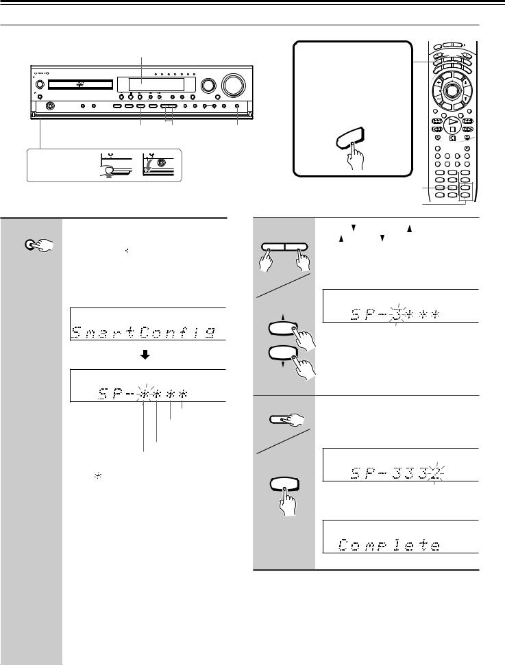
Speaker Setup
 Setting up the speaker configuration using Smart Configuration
Display
|
|
|
DVD/CD VIDEO 1 VIDEO 2 TV/LINE TAPE/MD FM AM |
VOLUME |
STANDBY/ON |
|
|
|
INPUT |
ON |
|
|
|
|
STANDBY |
|
|
|
|
POWER |
|
|
SURROUND STEREO Theater-Dimensional |
ACOUSTIC |
|
|
CONTROL |
||
ON OFF |
|
|
TUNER PRESET |
|
SPEAKER A/B SUBWOOFER |
TEST TONE DISTANCE CH SEL |
Theater-Dimensional DOWN UP FM MODE PRESET MEORY |
TUNING DISPLAY SPEAKER SETUP |
|
PHONES |
MODE |
|
SETUP |
|
|
|
3 |
2 |
1 |
Press the lower |
ON |
OFF |
ON OFF |
|
part of the cover |
|
|
PHONES |
|
to open. |
|
|
|
|
1 Unit only
SPEAKER SETUP
Press SPEAKER SETUP.
“SmartConfig” appears in the display, then “SP-


 ” appears shortly after.
Note
If any display appears other than “SmartConfig,” press the button repeatedly until “SmartConfig” appears.
Subwoofer field
Surround left and right speaker field
Center speaker field
Front left and right speaker field
Each “ ” is the field to enter the speaker identification number.
The flashing field is currently selected.
Before operating the remote controller
Press MODE AUDIO.
The remote controller remains in the AUDIO mode until another MODE button is pressed.
EEP |
|
ON |
|
STNBY |
|
|
||||
|
|
|
|
|
|
|
|
|
||
SL |
|
|
|
|
|
|
|
|
|
|
|
|
|
INPUT |
S |
L |
|
|
|
|
|
|
|
|
E ECTOR |
|
|
|||||
|
|
|
|
MO DE |
|
|
|
|
||
O |
|
DVD |
M |
TA/MD |
TV |
|||||
ENING |
|
|
|
|||||||
UDI |
|
ODE |
|
|
||||||
A |
IST |
|
|
|
T – D |
|
|
|
||
L |
STEREO |
|
A. |
|
||||||
R |
|
|
|
|
|
|
|
|
||
R |
|
|
|
|
|
|
|
|
C |
|
U |
|
|
|
|
|
|
|
|
|
TR |
S |
|
|
|
|
|
|
|
|
|
L |
|
|
|
|
LE |
|
ME |
NU |
|
|
|
|
|
TIT |
|
|
|
|
||||
CH |
|
|
|
ENTER |
|
|
VOL |
|||
TUN |
|
|
|
|
|
|||||
|
|
|
|
|
|
|
|
|
|
|
|
|
R |
|
|
|
|
P |
|
|
|
|
|
|
ET |
URN |
|
SE |
|
R |
|
|
REPEAT |
|
|
|
|
/VC |
MUTING |
||||
|
|
|
|
|
TV |
|
|
|||
|
|
A – B |
|
DIMMER |
|
|||||
IO |
REC |
|
|
OPEN/CLOSE |
|
|
|
|
|
|
|
D |
|
|
|
|
|
U |
|
|
|
|
|
A |
RANDOM |
|
|
|
SLOW |
|
SUBTITLE – ON / OFF |
ANGLE |
ZOOM |
||
|
MEMORY CLEAR |
AUDIO |
DISPLAY |
||
|
SW MODE TEST TONE |
|
|
||
|
1 |
2 |
|
|
3 |
|
LATE NIGHT DISTANCE |
|
|
||
3 |
4 |
5 |
|
|
6 |
SP A |
CH SEL |
|
|
||
7 |
8 |
|
|
9 |
|
SP B |
T– D SETUP |
UP/ DOWN |
|||
2 |
+10 |
0 |
|
|
SEARCH |
-- / --- |
|
|
|
|
|
|
|
|
|
|
|
2 Unit |
Press |
DOWN/UP |
on the unit or |
||||
UP |
/DOWN |
on the remote |
|||||
|
|
||||||
|
|
controller to enter the speaker |
|||||
|
DOWN UP |
identification number. |
|||||
|
|
|
|
|
|
||
|
|
Find the speaker identification number in |
|||||
|
|
the tables on the previous page. |
|||||
Remote controller |
|
|
|
|
|
||
|
9 |
Notes |
|
|
|
|
|
|
UP/ DOWN |
|
|
|
|
||
|
• If no speaker is connected, select “0.” |
||||||
|
|
||||||
|
SEARCH |
(There is no “0” setting for the front left and |
|||||
|
|
right speakers since they must be connected.) |
|||||
|
|
• If any speaker other than the speakers listed |
|||||
|
|
in the table is connected, select “9.” |
|||||
3 |
Unit |
Press CH SEL to select the next |
|||||
|
|||||||
|
|
field. |
|
|
|
|
|
|
CH SEL |
Repeat steps 2 and 3 until you finish the |
|||||
|
|
subwoofer field. |
|
|
|||
Remote controller |
|
|
|
|
|
||
|
CH SEL |
|
|
|
|
|
|
|
|
Smart Configuration is complete when the |
|||||
|
|
subwoofer field is set. |
|
||||
Tips
•If a speaker field is set to “9,” adjust its volume balance manually.
See “Adjusting Each Speaker's Relative Volume Balance– Test Tone” on page 21.
•For precise setting, carry out “Setting the Distance From the
Listening Position to Each Speaker” on page 20.
18
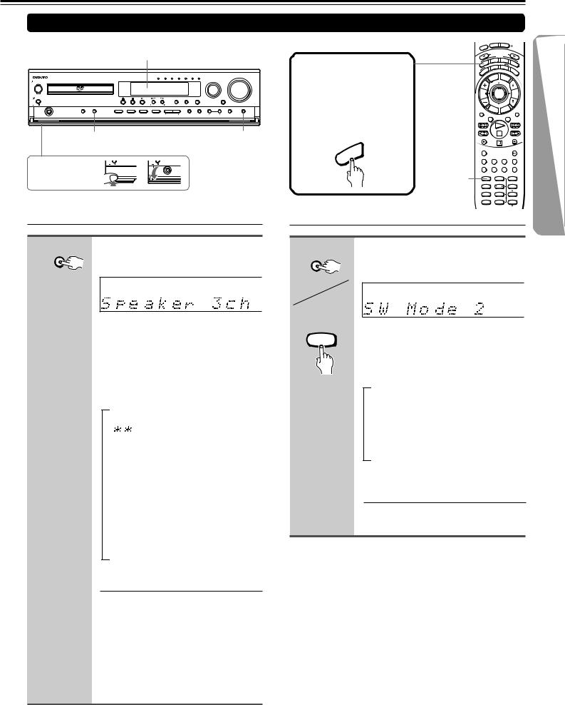
Setting up Non-Onkyo Speakers
Display
|
|
|
DVD/CD VIDEO 1 VIDEO 2 TV/LINE TAPE/MD |
FM |
AM |
|
VOLUME |
|
STANDBY/ON |
|
|
|
|
|
|
INPUT |
|
ON |
|
|
|
|
|
|
|
|
STANDBY |
|
|
|
|
|
|
|
|
POWER |
|
|
SURROUND |
STEREO |
Theater-Dimensional |
|
ACOUSTIC |
|
|
|
|
CONTROL |
|||||
ON OFF |
|
|
TUNER PRESET |
|
|
|
|
|
|
SPEAKER A/B SUBWOOFER |
TEST TONE DISTANCE |
CH SEL Theater-Dimensional DOWN UP |
FM MODE PRESET MEORY |
TUNING |
DISPLAY SPEAKER SETUP |
||
PHONES |
MODE |
|
SETUP |
|
|
|
|
|
SUBWOOFER |
SPEAKER |
|
MODE |
|
SETUP |
Press the lower |
ON OFF |
ON OFF |
part of the cover |
|
PHONES |
to open. |
|
|
 Selecting the number of speaker channels
Unit only |
Press SPEAKER SETUP repeatedly |
|
to select the number of channels |
SPEAKER SETUP |
for the SPEAKERS A system. |
|
Although “SmartConfig” may appear in the display, do not select “SmartConfig” in this step.
Within three seconds, press the button repeatedly. The number of channels changes as follows (the corresponding speaker configuration is described in parentheses):
→ SmartConfig
Do not select this in this step. If “SP-


 ” appears, you can move to the next setting by pressing SPEAKER SETUP.
↓
Speaker 2ch
(Front left and right speakers)
↓
Speaker 3ch
(Front left, center, and right speakers)
↓
Speaker 4ch
(Front left and right, plus surround left
and right speakers)
↓
Speaker 5ch
(Front left, center, and right, plus surround left and right speakers)
The normal display resumes in three seconds.
Notes
•The listening mode will automatically be set to “Stereo” (see page 38) once you set or reset the number of channels.
•To check the present setting while the normal display is displayed, press SPEAKER SETUP once. To change the setting, press the button repeatedly within three seconds.
Before operating the remote controller
Press MODE AUDIO.
The remote controller remains in the AUDIO mode until another MODE button is pressed.
EEP |
|
ON |
|
STNBY |
|
|
||||
|
|
|
|
|
|
|
|
|
||
SL |
|
|
|
|
|
|
|
|
|
|
|
|
|
INPUT |
S |
L |
|
|
|
|
|
|
|
|
E ECTOR |
|
|
|||||
|
|
|
|
MO DE |
|
|
|
|
||
O |
|
DVD |
M |
TA/MD |
TV |
|||||
ENING |
|
|
|
|||||||
UDI |
|
ODE |
|
|
||||||
A |
IST |
|
|
|
T – D |
|
|
|
||
L |
STEREO |
|
A. |
|
||||||
R |
|
|
|
|
|
|
|
|
||
R |
|
|
|
|
|
|
|
|
C |
|
U |
|
|
|
|
|
|
|
|
|
TR |
S |
|
|
|
|
|
|
|
|
|
L |
|
|
|
|
LE |
|
ME |
NU |
|
|
|
|
|
TIT |
|
|
|
|
||||
CH |
|
|
|
ENTER |
|
|
VOL |
|||
TUN |
|
|
|
|
|
|||||
|
|
|
|
|
|
|
|
|
|
|
|
|
R |
|
|
|
|
P |
|
|
|
|
|
|
ET |
URN |
|
SE |
|
R |
|
|
REPEAT |
|
|
|
|
|
TV |
|
|
MUTING |
|
|
|
A – B |
|
DIMMER |
|
|||||
REC |
|
|
|
|
|
|
OPEN/CLOSE |
|||
IO |
|
RANDOM |
|
|
SLOW |
|
|
|
|
|
|
D |
|
SUBTITLE – ON / OFF |
ANGLE |
ZOOM |
|
U |
|
||||
A |
|
|
|
|
|
|
|
MEMORY CLEAR |
AUDIO |
DISPLAY |
|
|
SW MODE |
SW MODE TEST TONE |
|
||
|
1 |
2 |
|
3 |
|
|
|
LATE NIGHT DISTANCE |
|
||
|
|
4 |
5 |
|
6 |
|
|
SP A |
CH SEL |
|
|
|
|
7 |
8 |
|
9 |
|
|
SP B |
T– D SETUP UP/ DOWN |
||
|
|
+10 |
0 |
|
SEARCH |
-- / ---
 Setting the Subwoofer Mode
Unit |
SUBWOOFER |
MODE |
Remote controller |
SW MODE |
1 |
Press SUBWOOFER MODE on the unit or SW MODE on the remote controller.
With the first press of the button, you can check the present setting. Then each press of the button changes the subwoofer mode as follows (a tip on how to select the right subwoofer mode is in parentheses):
→SW Mode 2
(When large–wideband–front speakers
are connected)
↓
SW Off
(When no subwoofer is connected)
↓
SW Mode 1
(When small–with limited bass signal handling–front speakers are connected)
The normal display resumes in three seconds.
19
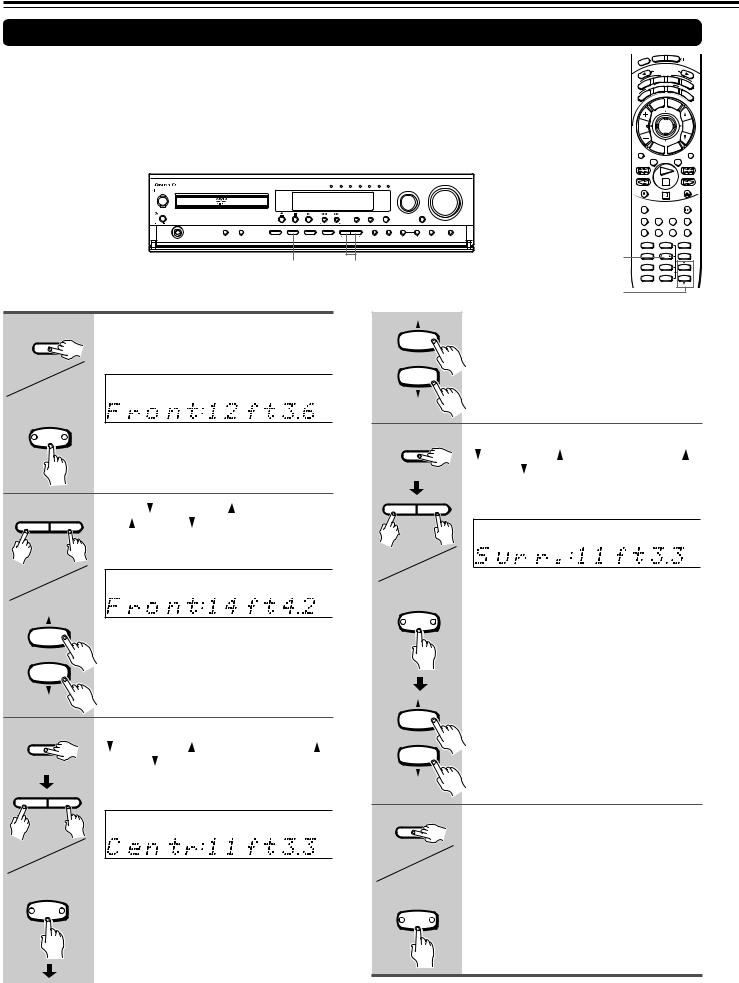
Speaker Setup
Setting the Distance From the Listening Position to Each Speaker
Before starting the procedure below, measure the distances from each speaker to the listening position.
For pair speakers such as front left and right speakers, the distance from the listening position to one speaker should be the same as the distance to the other.
In the procedure below, select the values which approximate the actual distances.
EEP |
|
ON |
|
STNBY |
|
|
||||
|
|
|
|
|
|
|
|
|
||
SL |
|
|
|
|
|
|
|
|
|
|
|
|
|
INPUT |
S |
L |
|
|
|
|
|
|
|
|
E ECTOR |
|
|
|||||
|
|
|
|
MO DE |
|
|
|
|
||
O |
|
DVD |
M |
TA/MD |
TV |
|||||
ENING |
|
|
|
|||||||
UDI |
|
ODE |
|
|
||||||
A |
IST |
|
|
|
T – D |
|
|
|
||
L |
STEREO |
|
A. |
|
||||||
R |
|
|
|
|
|
|
|
|
||
R |
|
|
|
|
|
|
|
|
C |
|
U |
|
|
|
|
|
|
|
|
|
TR |
S |
|
|
|
|
|
|
|
|
|
L |
|
|
|
|
LE |
|
ME |
NU |
|
|
|
|
|
TIT |
|
|
|
|
||||
CH |
|
|
|
ENTER |
|
|
VOL |
|||
TUN |
|
|
|
|
|
|||||
|
|
|
|
|
|
|
|
|
|
|
|
|
R |
|
|
|
|
P |
|
|
|
|
|
ET |
|
|
TU |
R |
|
|
||
REPEAT |
|
|
|
URN |
|
/VC |
MUTING |
|||
|
|
|
|
|
TV |
|
|
|||
|
|
A – B |
|
DIMMER |
|
|||||
DVD/CD VIDEO 1 VIDEO 2 TV/LINE TAPE/MD FM |
AM |
VOLUME |
|
|
|
|
STANDBY/ON |
|
|
|
|
|
|
INPUT |
|
|
|
|
REC |
|
|
OPEN/CLOSE |
|
|
|
|
ON |
|
|
|
|
|
|
|
|
|
|
|
|
|
|
|
|
|
|
|
|
|
|
|
|
|
|
|
|
|
|
|
RANDOM |
|
|
SLOW |
|
|
|
|
STANDBY |
|
|
|
|
|
|
|
|
|
|
|
|
|
|
|
|
|
|
|
POWER |
|
|
|
|
SURROUND STEREO Theater-Dimensional |
ACOUSTIC |
|
|
|
|
|
|
|
||
|
|
|
|
|
|
|
|
CONTROL |
|
|
|
SUBTITLE – ON / OFF |
ANGLE ZOOM |
||||||
|
|
|
|
ON OFF |
|
|
|
TUNER PRESET |
|
|
|
|
|
|
|
|
|
|
|
|
|
|
|
|
|
|
|
|
|
|
|
|
|
|
|
MEMORY CLEAR |
AUDIO DISPLAY |
||
|
|
|
|
|
SPEAKER A/B SUBWOOFER |
TEST TONE DISTANCE CH SEL |
Theater-Dimensional |
DOWN UP |
FM MODE PRESET MEORY |
TUNING |
DISPLAY SPEAKER SETUP |
|
|
|
|
|
|
|
|
|
|
|
|
PHONES |
|
MODE |
|
SETUP |
|
|
|
|
|
|
|
SW MODE TEST TONE |
|
||
|
|
|
|
|
|
|
|
|
|
|
|
|
|
|
1,3-5 |
1 |
2 |
|
3 |
|
|
|
|
|
|
|
|
|
|
|
|
|
|
|
SP A |
CH SEL |
|
||
|
|
|
|
|
|
|
|
|
|
|
|
|
|
|
|
LATE NIGHT DISTANCE |
|
||
|
|
|
|
|
|
|
1,3-5 |
2-4 |
|
|
|
|
|
4 |
5 |
|
6 |
||
|
|
|
|
|
|
|
|
|
|
|
|
+10 |
0 |
|
SEARCH |
||||
|
|
|
|
|
|
|
|
|
|
|
|
|
|
|
|
7 |
8 |
|
9 |
|
|
|
|
|
|
|
|
|
|
|
|
|
|
|
|
SP B T– D SETUP |
UP/ DOWN |
||
|
|
|
|
|
|
|
|
|
|
|
|
|
|
|
2-4 |
-- / --- |
|
|
|
|
|
|
|
|
|
|
|
|
|
|
|
|
|
|
|
|
|
|
|
1 |
Unit |
Press DISTANCE. |
|
|
|
|
|
|
|
Note |
|
|
|
|
|
|
|||
|
|
|
|
|
9 |
|
If you selected a speaker configuration with no |
||||||||||||
|
The distance entry display for the front left |
|
|
|
center speaker on the page 18 or 19, this step |
||||||||||||||
|
DISTANCE |
and right speakers appears. |
|
|
|
UP/ DOWN |
will be skipped. |
|
|
|
|
|
|||||||
|
|
|
|
|
|
|
|
|
|
|
|
|
|
|
|
|
|
|
|
|
|
|
|
|
|
|
|
|
|
SEARCH |
|
|
|
|
|
|
|
||
|
Remote |
|
|
|
|
|
|
|
|
|
|
|
|
|
|
|
|
|
|
|
controller |
|
|
|
|
|
|
m |
|
|
|
|
|
|
|
|
|
|
|
|
DISTANCE |
|
|
|
|
|
|
|
|
4 |
|
|
|
|
|
|
|
|
|
|
|
|
|
|
|
|
|
|
|
Unit |
Press DISTANCE, then press |
|
|
|
|||||
|
|
|
|
|
|
|
|
|
|
|
|
|
|
||||||
|
|
|
|
|
|
|
|
|
|
|
|
|
DOWN/UP |
on the unit or UP |
/ |
||||
|
|
|
|
|
|
|
|
|
|
DISTANCE |
DOWN |
on the remote controller |
|||||||
|
|
|
|
|
|
|
|
|
|
|
|
|
repeatedly to select the surround |
||||||
2 Unit |
Press |
DOWN/UP |
on the unit or |
|
|
|
|
left and right speaker distance. |
|
||||||||||
|
|
|
|
|
|
|
|
|
|
|
|||||||||
|
|
UP |
/DOWN |
on the remote |
|
|
DOWN |
UP |
|
|
|
|
|
|
|
||||
|
DOWN UP |
controller to select the front left and |
|
|
|
|
|
|
|
|
|
|
|
||||||
|
|
right speaker distance. |
|
|
|
|
|
|
|
|
|
|
|
|
m |
||||
|
|
|
|
|
|
|
|
|
|
|
|
|
|
|
|||||
|
|
|
|
|
|
|
|
|
|
|
Remote |
You cannot enter the following distances: |
|||||||
|
Remote |
|
|
|
|
|
|
|
|
|
controller |
||||||||
|
|
|
|
|
|
|
m |
|
DISTANCE |
• Distances longer than the distance set |
|||||||||
|
controller |
|
|
|
|
|
|
|
|
||||||||||
|
|
|
|
|
|
|
|
|
for the front speakers. |
|
|
|
|
||||||
|
|
|
|
|
|
|
|
|
|
|
|
|
|
|
|
|
|||
|
9 |
You can select a distance between 0.3 m |
|
|
|
|
• Distances shorter than the distance |
|
|||||||||||
|
|
|
|
|
obtained by subtracting “4.5 m (15 ft.)” |
||||||||||||||
|
UP/ DOWN |
and 9 m (1 ft. and 30 ft.). |
|
|
|
|
|
|
|
||||||||||
|
|
|
|
|
|
|
|
from the distance entered for the front |
|||||||||||
|
SEARCH |
|
|
|
|
|
|
|
|
|
|
|
|||||||
|
|
|
|
|
|
|
|
|
|
|
|
speakers. |
|
|
|
|
|
||
|
|
|
|
|
|
|
|
|
|
|
|
|
Note |
|
|
|
|
|
|
3 |
|
|
|
|
|
|
|
|
|
|
9 |
|
If you selected a speaker configuration with no |
||||||
Unit |
Press DISTANCE, then press |
|
|
|
|
surround speakers on page 18 or 19, this step |
|||||||||||||
|
|
UP/ DOWN |
will be skipped. |
|
|
|
|
|
|||||||||||
|
DOWN/UP |
on the unit or UP |
/ |
|
|
|
|
|
|
||||||||||
|
|
SEARCH |
|
|
|
|
|
|
|
||||||||||
|
|
DOWN |
on the remote controller |
|
|
|
|
|
|
|
|
||||||||
|
DISTANCE |
|
|
|
|
|
|
|
|
|
|
|
|||||||
|
|
repeatedly to select the center |
|
|
|
|
|
|
|
|
|
|
|
|
|||||
|
|
speaker distance. |
|
|
|
|
5 |
|
|
|
|
|
|
|
|
|
|||
|
DOWN UP |
|
|
|
|
|
|
|
|
Unit |
Press DISTANCE. |
|
|
|
|
||||
|
|
|
|
|
|
|
|
|
|
|
|
|
|
||||||
|
|
|
|
|
|
|
|
m |
|
|
|
|
The normal display resumes. |
|
|
|
|
||
|
|
|
|
|
|
|
|
|
DISTANCE |
|
|
|
|
|
|
|
|||
|
|
|
|
|
|
|
|
|
|
|
|
|
|
|
|
|
|||
|
Remote |
You cannot enter the following distances: |
|
|
Remote |
|
|
|
|
|
|
|
|||||||
|
controller |
|
|
|
|
|
|
|
|
|
|||||||||
|
|
controller |
|
|
|
|
|
|
|
||||||||||
DISTANCE |
• Distances longer than the distance set |
|
|
|
|
|
|
|
|
||||||||||
|
DISTANCE |
|
|
|
|
|
|
|
|||||||||||
|
|
for the front speakers. |
|
|
|
|
|
|
|
|
|
|
|
||||||
|
|
|
|
|
|
|
|
|
|
|
|
|
|
|
|
||||
|
|
• Distances shorter than the distance |
|
|
|
|
|
|
|
|
|
|
|
|
|||||
|
|
obtained by subtracting “1.5 m (5 ft.)” |
|
|
|
|
|
|
|
|
|
|
|
|
|||||
|
|
from the distance entered for the front |
|
|
|
|
|
|
|
|
|
|
|
|
|||||
|
|
speakers. |
|
|
|
|
|
|
|
|
|
|
|
|
|
|
|
||
20
Adjusting Each Speaker's Relative Volume Balance– Test Tone
Adjust each speaker’s relative volume balance so that the volumes of all speakers’ test tones sound equal at the listening position.
|
|
|
DVD/CD VIDEO 1 VIDEO 2 TV/LINE TAPE/MD |
FM |
AM |
|
VOLUME |
|
STANDBY/ON |
|
|
|
|
|
|
INPUT |
|
ON |
|
|
|
|
|
|
|
|
STANDBY |
|
|
|
|
|
|
|
|
POWER |
|
|
SURROUND |
STEREO |
Theater-Dimensional |
|
ACOUSTIC |
|
|
|
|
CONTROL |
|||||
ON OFF |
|
|
TUNER PRESET |
|
|
|
|
|
|
SPEAKER A/B SUBWOOFER |
TEST TONE DISTANCE |
CH SEL Theater-Dimensional DOWN UP |
FM MODE PRESET MEORY |
TUNING |
DISPLAY SPEAKER SETUP |
||
PHONES |
MODE |
|
SETUP |
|
|
|
|
|
1,3 2 2
|
|
EEP |
|
ON |
STNBY |
|
|
|||
|
|
|
|
|
|
|
|
|
|
|
|
SL |
|
|
|
|
|
|
|
|
|
|
|
|
|
|
S |
L |
|
|
|
|
|
|
|
|
INPUT E |
ECTOR |
|
|
|||
|
|
|
|
|
MO DE |
|
|
|
|
|
|
|
|
|
DVD |
TA/MD |
|
|
|||
|
|
O |
|
|
M |
|
|
|
TV |
|
|
UDI |
ENING ODE |
|
|
||||||
|
A |
IST |
|
|
T – D |
|
|
|
||
|
|
L |
STEREO |
|
A. |
|
||||
|
|
R |
|
|
|
|
|
|
|
|
|
|
R |
|
|
|
|
|
|
C |
|
|
|
U |
|
|
|
|
|
|
|
TR |
|
S |
|
|
|
|
|
|
|
L |
|
|
|
|
|
|
LE |
ME |
NU |
|
|
|
|
|
|
TIT |
|
|
|
||||
|
CH |
|
|
ENTER |
|
|
VOL |
|||
|
TUN |
|
|
|
|
|
|
|
|
|
|
|
|
R |
|
|
|
P |
|
|
|
|
|
|
|
ET |
URN |
SE |
|
R |
|
|
|
REPEAT |
|
|
|
TV |
|
|
MUTING |
||
|
|
A – B |
DIMMER |
|
||||||
|
REC |
|
|
|
|
|
OPEN/CLOSE |
|||
|
RANDOM |
|
|
|
|
|
|
SLOW |
||
|
SUBTITLE – ON / OFF |
ANGLE |
ZOOM |
|||||||
|
MEMORY CLEAR |
AUDIO |
DISPLAY |
|||||||
1,3 |
SW MODE TEST TONE |
|
|
|
||||||
|
1 |
|
|
2 |
|
|
|
3 |
|
|
LATE NIGHT DISTANCE |
|
|
|
|
||||||
2 |
|
4 |
|
|
5 |
|
|
|
6 |
|
|
SP A |
|
|
CH SEL |
|
|
|
|
||
|
7 |
|
|
8 |
|
|
|
9 |
|
|
|
SP B |
|
|
T– D SETUP |
|
UP/ DOWN |
||||
2 |
|
+10 |
|
|
0 |
|
|
|
SEARCH |
|
|
-- / --- |
|
|
|
|
|
|
|
||
|
|
|
|
|
|
|
|
|
|
|
1 Unit |
TEST TONE |
Remote controller |
TEST TONE |
2 |
Press TEST TONE.
Each speaker emits the test tone (pink noise) and the display shows the speaker emitting the test tone in the following order:
Left |
→ |
Center |
(Front left ch.) |
(Center ch.) |
|
↑ |
|
↓ |
Subwfr |
|
Right |
(Subwoofer) |
|
(Front right ch.) |
↑ |
← |
↓ |
Surr L |
Surr R |
|
(Surround left ch.) |
(Surround right ch.) |
|
dB
Note
No test tone will be emitted from the speaker which is not included in the speaker configuration on page 18 or 19 even if it is actually connected.
2 |
Unit |
Press CH SEL repeatedly to select |
||
|
|
the speaker, then press |
DOWN/ |
|
|
CH SEL |
UP |
on the unit or UP |
/DOWN |
|
on the remote controller to adjust |
|||
|
|
|||
|
|
the volume level. |
|
|
|
|
The volume level can be adjusted between |
||
|
DOWN UP |
–12dB and +12dB. |
|
|
Remote controller |
|
|
|
|
|
CH SEL |
|
|
|
|
9 |
|
|
|
|
UP/ DOWN |
|
|
|
|
SEARCH |
|
|
|
3 |
Unit |
When you have completed the |
||
|
adjustment by repeating step 2, |
|||
|
TEST TONE |
press TEST TONE. |
|
|
|
|
The test tone stops and the normal display |
||
|
|
resumes. |
|
|
Remote controller |
Note |
|
|
|
TEST TONE |
Even if you don’t press TEST TONE, the test |
|||
|
2 |
tone will stop after 10 cycles. |
|
|
|
|
|
|
|
21

Basic Operation
Playing DVDVideos /VIDEO CDs /Audio CDs
Before playing
•DVD Videos, VIDEO CDs, and audio CDs can be played with the DVD Receiver (see “Playable Discs” on page 9). Do not play anything else.
•When playing DVD videos and VIDEO CDs, turn on the TV and set the TV to the DVD Receiver’s input.
About the |
DVD |
, |
|
, and |
CD |
marks in the pages related to |
|||||||||||
VCD |
|||||||||||||||||
|
|
|
|||||||||||||||
|
|
|
|||||||||||||||
DVD video/VIDEO CD/audio CD operation |
|||||||||||||||||
|
|
DVD |
|
|
means “The function or title is related to DVD operation.” |
||||||||||||
|
|
|
|
|
|
|
|||||||||||
|
|
|
|
|
|
means “The function or title is related to VIDEO CD operation.” |
|||||||||||
VCD |
|||||||||||||||||
|
|
||||||||||||||||
|
|
|
CD |
|
|
means “The function or title is related to audio CD operation.” |
|||||||||||
|
|
|
|
|
|
||||||||||||
|
|
|
|
|
|
|
|
|
|
||||||||
|
DVD |
|
|||||||||||||||
|
|
|
|
VCD |
|
CD |
|||||||||||
DVD If the screen on the right appears – Screen Saver
If you pause a picture for a long while, the screen saver operates.
To resume normal display, press s.
(You can set this function to Off. See page 57.)
DVD To play NTSC discs (Multisystem TV is needed)
VCD Set “PAL/Auto” to “Auto” using the menu explained in “Customizing the Function Settings” starting from page 52. See page 55 for direct information.
Basic Playback
1 Press r. |
If the DVD Player is in standby mode when the button is pressed |
The DVD Player turns on and the disc tray opens. In this case, it takes |
|
The disc tray opens. |
several seconds until the disc tray opens. |
2 Place the disc on the disc tray.
STANDBY/ON
ON
Put the disc in the tray with the label side facing up. |
STANDBY |
Lit while the input source is |
There are two different disc sizes. Place the disc in |
POWER |
the built-in DVD player. |
ON OFF |
the correct guide on the disc tray.
|
|
DVD/CD VIDEO 1 VIDEO 2 TV/LINE TAPE/MD FM AM |
VOLUME |
|
CAUTION |
ON |
|
INPUT |
|
|
STANDBY/ON |
|
|
|
Keep your fingers well |
|
|
|
|
clear of the disc tray as |
STANDBY |
|
ACOUSTIC |
|
it is closing. |
POWER |
SURROUND STEREO Theater-Dimensional |
||
CONTROL |
||||
|
||||
Neglecting to do so may |
ON OFF |
TUNER PRESET |
|
|
cause serious personal |
|
|
|
|
injury. |
The r(open/close), e(stop), and |
s(play) |
|
|
|
|
|||
|
buttons/lamps are lit while the DVD Receiver is |
|
||
|
On. |
|
|
|
3 Press s.
The disc tray closes and playback starts.
If you press rto close the tray after step 2, playback may automatically start depending on the disc.
One of the indicators, which indicate the digital sound format of the playing source, lights.
DOLBY DIGITAL, DTS, MPEG (for MPEG2 sound), PCM (2 channel digital stereo)
DOLBY DIGITAL DTS MPEG PCM |
DVD |
The type of the inserted disc lights.
For the other information that appears in the display, see pages 50 and 51.
DVD
VCD
DVD
CD
If a title menu appears on the TV screen
The DVD video has a title menu, or the VIDEO CD is equipped with the PBC (Playback Control) function. Follow steps 2 and 3 in “Locating a title using the title menu” on page 25.
For details about the PBC function, see “About VIDEO CDs” on page 9. To start playback with or without using the PBC function, see page 59.
If a sound selection menu appears on the TV screen
See “Enjoying the Sound Effects” on page 34 for details of the sound systems. Select the appropriate sound using  /
/
 /
/ /
/ , then press ENTER (see the illustration of the remote controller on the opposite page).
For example, if you need to select either “DTS” or “Stereo,” select “DTS” since the DVD Receiver is able to reproduce DTS (Digital Theater System) Surround sound.
If the sound is not reproduced from the beginning of the disc
See the first note in the lower right corner of the opposite page.
22
 Loading...