


 Loading...
SafetyStock Technical Guide
Functional Overview and Implementation Instructions
© 2008 Omnicell, Inc. |
SafetyStock Technical Guide/67-3025 Rev C |

This guide is CONFIDENTIAL and designed only for Omnicell Technical personnel and/or designated representatives.
This guide and accompanying software and/or hardware described in it are protected under copyright laws and may not be copied, wholly or in part, without the express written consent of Omnicell, Inc. The same proprietary and copyright notices must be attached to any permitted copies as were attached to the original works.
Omnicell, Inc.
1201 Charleston Road Mountain View, CA 94043 (650) 251-6100 www.omnicell.com
OMNICELL, ANESTHESIA TT, DECISIONCENTER, FLEXBIN, MEDGUARD, OMNIBUYER, OMNICENTER, OMNIEVOLVE, OMNIFLOORSTOCK, OMNIGATE, OMNILINKRX, OMNIRX, OMNISCANNER, OMNISUPPLIER, OMNITRACK, ONSITE, OPEN TOUCH, OPTIFLEX, OPTIFLEX MOBILETRACK, PHARMACYCENTRAL, POINT-TO-POINT MEDICATION SAFETY, PROSERV1, SAFETYMED, SAFETYPAK, SAFETYSTOCK, SECUREVAULT, SEE & TOUCH, SINGLEPOINTE, SURE-MED, TOUCH & GO, VCOMMANDER, VDIRECTOR, VMANAGER, VSUITE, WORKFLOWRX, and the OMNICELL design mark are trademarks or registered trademarks of Omnicell, Inc. in the United States and internationally.
©1999 - 2008 All rights reserved.
SafetyStock Technical Guide/67-3025 Rev C |
© 2008 Omnicell, Inc. |

1-1
SafetyStock
SafetyStock™ is a bar code confirmation system that promotes patient safety by minimizing the opportunity for stocking and dispensing errors. SafetyStock users scan bar codes to confirm the identity of medication and supply products for restock, selected issues, and returns to the Color Touch cabinet.
Technical Overview
SafetyStock is an Omnicell option. It requires the purchase of an Option Key. Restock, Issue and
Bin Bar Code Confirmation functions will not work until SafetyStock is properly enabled. Other related features and enhancements, such as Automatic Stock-out, function independently of
SafetyStock and do not require an Option Key. The SafetyStock feature is primarily used for medication restocking and issuing functions, however, can also be used for supply items.
Existing cabinet functionality directs both the pharmacy technician and the nurse to the correct location during restock and issue transactions. SafetyStock provides an additional layer of safety, using bar code scanning to ensure that medication items are restocked correctly and, if so configured, that the correct medication is issued from the cabinet.
SafetyStock is also designed for facilities using Omnicell WorkflowRx. In such cases, SafetyStock uses the Restock Labels generated by WorkflowRx, and is able to receive restock information from and send restock confirmations to WorkflowRx. For non-WorkflowRx accounts, Pick and Restock labels and reports are generated at the OmniScanner Shelf Label Bar Code. In either case, an approved model of SATO printer is required (see System Requirements/Compatibility).
SafetyStock bar code confirmation involves three primary elements:
Labeling and scanning for restock confirmation
Labeling and scanning for issue and return confirmation (optional)
Labeling and scanning for bin location confirmation (optional)
In addition, the following restock options and enhancements are introduced with this feature:
Selective Restock
Allows users to manually generate a restock at the OmniCenter for select items, outside of the normal restock process.
Automatic stock-out restock generation
Automatically generates a restock for specified items that reach a zero quantity, within a configurable time period prior to normal restock.
Customizable default printer settings
Provide the ability to specify different default printers for various functions, such as restock reports and label printing.
Restock tab user interface changes
Feature separates screens for restock by route, by cabinet, by item (Selective Restock), and for reprints, along with numerous other UI enhancements.
© 2008 Omnicell, Inc. |
SafetyStock Technical Guide/67-3025 Rev C |

1-2 SafetyStock
Hardware Installation
Addition of Restock Configuration section to Administration tab, Setup Admin Type.
New Restock Configuration screens allow users to set defaults for various restock functions, such as default printer settings.
System Requirements/Compatibility
OmniCenter and Color Touch cabinets running Omnicell 8100 software or higher. Blue Screen and Sure-Med DOS cabinets are not supported.
A supported Symbol bar code scanner at the OmniCenter.
A supported Symbol bar code scanner at each cabinet.
One scanner per software host, maximum distance equal to three cells, side-by-side.
A SATO printer to generate restock labels.
A valid Omnicell Option Key (encrypted with the allowable number of cabinets).
Hardware Installation
This section covers the hardware installation of the SafetyStock scanner (for various cabinet types). Installation can be performed at the customer facility by a qualified Omnicell representative.
Important: SafetyStock is only supported on Color Touch cabinets running Omnicell 8100 software (5.5.1.x) or higher.
Overview
Hardware installation procedures vary by product. Each type uses a different kit:
OmniRX, Half-Cell, or OmniRX TT [kit #20-6032]
Implant Tracking [kit #12-6006]
OmniSupplier [kit #20-6033]
OmniCenter or OCRA (OmniCenter Remote Access) machines [kit #20-6031]
SecureVault [kit #20-6039]
OmniRx, Half Cell, or OmniRx TT
The following instructions apply to SafetyStock scanner for OmniRx, Half Cell, or the OmniRX
TT using kit #20-6032.
Required Tools
T-10 Torx driver
ESD wristband
Cam lock key #2036
SafetyStock Technical Guide/67-3025 Rev C |
© 2008 Omnicell, Inc. |
SafetyStock 1-3
Hardware Installation
Required Kit/Parts
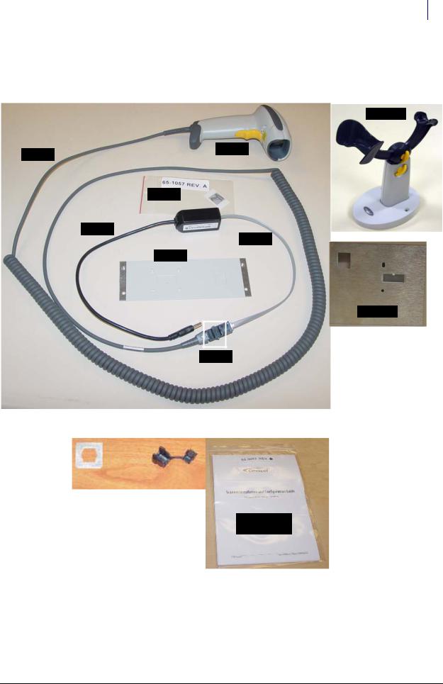
The following figures display the contents of the scanner kit (#20-6032). See “Parts/Kit List” on page A-1 for more kit details.
#70-6049
#70-6048
#88-6026
#65-1057
#88-0022
#42-1303
#53-3081
#53-1109
#82-6071
Figure 1-1. Kit #12-1266
|
|
Strain Relief |
AUX Cutout Bracket |
|
|
|
#91-2052 |
|
#53-7156 |
|
|
|
|
|
|
|
|
Scanner Document
#60-3003
Figure 1-2. Parts from kits #14-1244, #20-6032
Cabinet Preparation
1.Log on to the Administration menu.
2.Press Exit To Shell.
© 2008 Omnicell, Inc. |
SafetyStock Technical Guide/67-3025 Rev C |
1-4 SafetyStock
Hardware Installation
3.Press OK on the confirmation window.
4.Select the Shutdown On Exit option in the Exit the Shell section.
5.Press Exit The Shell.
6.Power down the cabinet and disconnect the power cord.
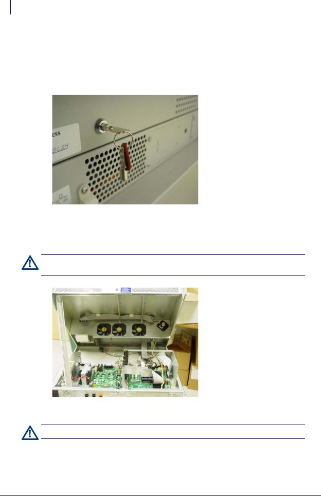
7.Unlock the cabinet top in the back using cam lock key #2036 (#92-1008).
Figure 1-3. Unlocking the cabinet top
8.Lift the cabinet top from the back on its hinge. The top is not removed.
9.Prop up the cabinet top with a stand. A switch panel extrusion can be used.
Caution: The cabinet lid is heavy and must be propped up securely. If it came down on its own, it could cause injury.
Figure 1-4. Accessing the electronics sled
Caution: Put on an ESD wristband and secure it to a ground before working in the electronics sled.
SafetyStock Technical Guide/67-3025 Rev C |
© 2008 Omnicell, Inc. |
SafetyStock 1-5
Hardware Installation
Cable Connections
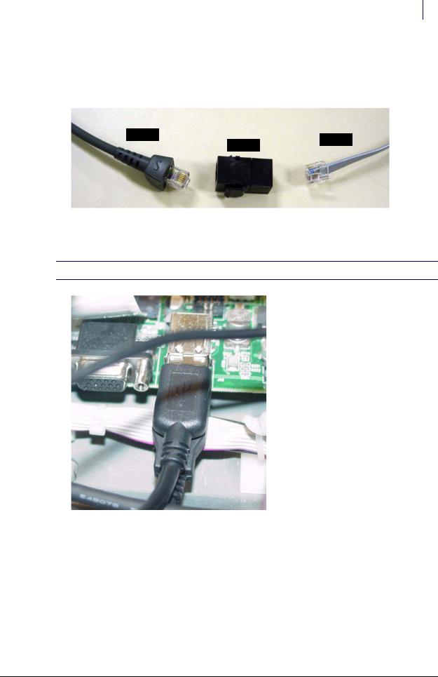
1.Disconnect the RJ-12 coupler from the #12-1266 Bar Code Scanner Manufacturing Assembly
Kit. The adapter cable (#42-1303) remains connected to the Synapse adapter and the USB cable (#88-0022). The scanner cable (#88-6026) remains connected to the scanner (#70-6048).
#88-6026
#42-1303
#82-6071
Figure 1-5. RJ-12 coupler from kit
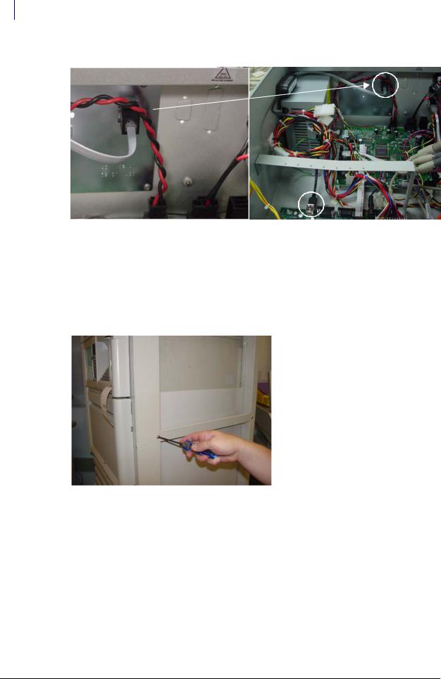
2. Connect the USB Synapse cable (#88-0022) from the kit into the mother board.
 Note: It may be necessary to move any existing USB cables to the lower USB port for ease of installment.
Figure 1-6. Connecting the USB cable to the motherboard
© 2008 Omnicell, Inc. |
SafetyStock Technical Guide/67-3025 Rev C |

1-6 SafetyStock
Hardware Installation
A number situations are possible concerning the coupler on the OmniRx. See the following table for the procedure that goes with the given situation. For all other cabinet types, go to Step 6.
|
|
Cutout big enough for |
|
Rear plate bracket present |
Aux Port Available |
RJ-12 Connector |
Next Step |
|
|
|
|
No |
Yes |
Yes |
Step 3 |
|
|
|
|
No |
Yes |
No |
Step 4 |
|
|
|
|
No |
No |
N/A |
Step 5 |
|
|
|
|
Yes |
N/A |
N/A |
Step 6 |
|
|
|
|
Table 1-1. OmniRx situations and related steps
 Important: Always use the kit’s plate to replace the rear plate bracket on the OmniRx (step 6) if it exists. This will avoid extra work later or sacrificing an Aux port for a future peripheral addition. Existing back plate brackets may not have a cutout for a remote antenna in case the OmniTT were to be made wireless later.
Available cutouts in the back of the sled may need to be punched out if there is no Aux port in place and no back plate bracket. These cutouts may be large enough for the RJ-12 coupler (step 3). If not, a strain relief is used to secure the cable to the sled (step 4) with the cable connected to the coupler outside the sled. Care is needed to ensure the cable is not easily disconnected.
Step 5 is used where there is no back plate bracket and no open Aux ports/cutouts. The scanner and Aux port share the same sled opening with cables connected to their couplers outside the sled. This method allows the addition of the scanner without sacrificing the use of the peripheral. Care is needed to ensure cables are not easily disconnected.
3.[OmniRX] If there is no rear plate bracket and the available Aux port cutout is large enough for the RJ-12 coupler, perform the following steps:
a.Disconnect the left most AUX coupler (as viewed from the back) and set it inside the sled with its cable (or) punch out the available cutout if there is no Aux port in place.
b.Install the RJ-12 coupler in the AUX coupler’s place.
c.Connect the adapter cable (#42-1303) to the in side of the RJ-12 coupler.
d.Proceed to Step 7.
4.[OmniRx] If there is no rear plate bracket and the available Aux port cutout is not large enough for the RJ-12 coupler, perform the following steps:
a.Disconnect the left most AUX coupler (as viewed from the back) and set it inside the sled with its cable (or) punch out the available cutout if there is no Aux port in place.
b.Thread the adapter cable (#42-1303) through the cutout bracket (#53-7156) inside the sled.
SafetyStock Technical Guide/67-3025 Rev C |
© 2008 Omnicell, Inc. |

SafetyStock 1-7
Hardware Installation
c. Feed the adapter cable (#42-1303) through the cutout opening.
Figure 1-7. Threading the communications cable (OmniRx)
d.Place the strain relief (#91-2052) around the cable on the exterior side.
e.Secure the strain relief around the cable in the cutout opening.
f.Secure cable position on sled interior with a cable tie (#95-6007). This prevents the cable from being pulled out during scanner use.
Cutout bracket and cable tie
Figure 1-8. Securing the adapter cable (#42-1303) (OmniRx)
g. Connect the adapter cable (#42-1303) to the RJ-12 coupler.
© 2008 Omnicell, Inc. |
SafetyStock Technical Guide/67-3025 Rev C |
1-8 SafetyStock
Hardware Installation
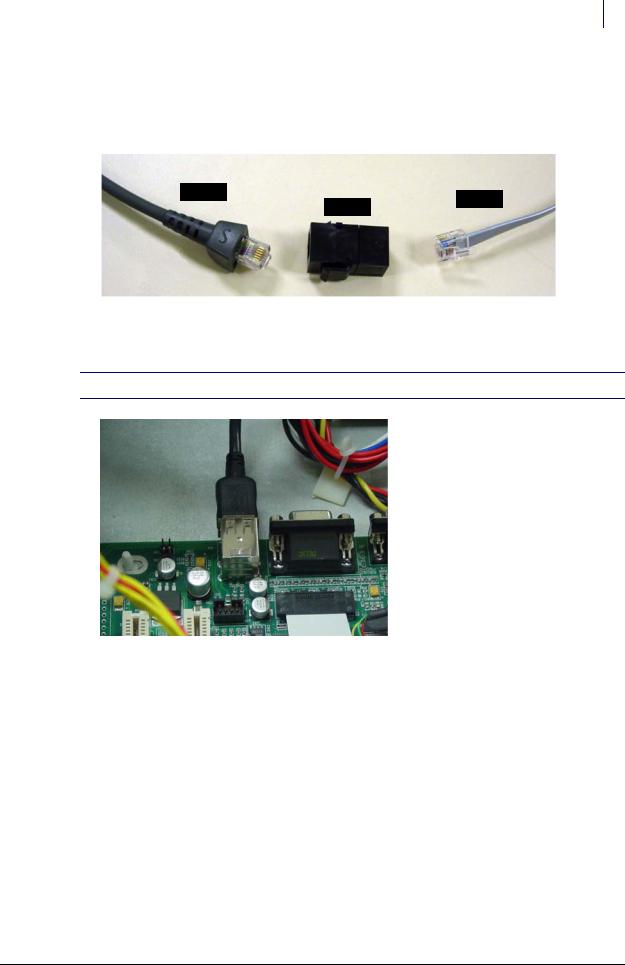
RJ12
Connector
Adapter
Cable
Scanner
Cable
Figure 1-9. Connecting the adapter cable (#42-1303) to the RJ-12 connector (OmniRx)
h.Proceed to Step 7.
5.[OmniRx] If there is no rear plate bracket and all coupler positions are being used, perform the following steps:
a.Disconnect the AUX cable inside the sled from right-most coupler (as viewed from the front) and remove the existing coupler.
b.Route both the adapter cable (#42-1303) and the AUX cable through the empty coupler hole.
c.Connect the cables to their coupler (adapter to RJ12, AUX to RJ-12) outside the sled, then bundle and secure the cables with a cable tie inside the sled.
d.Proceed to Step 7.
6.If there is a rear plate bracket, perform the following steps:
Note: This step is used for all cabinets (Half Cell, Anesthesia TT and OmniRX TT) and OmniRx with a rear plate bracket.
SafetyStock Technical Guide/67-3025 Rev C |
© 2008 Omnicell, Inc. |
SafetyStock 1-9
Hardware Installation
a. Punch out the cutout on the kit’s rear plate bracket (#53-3081).
Figure 1-10. Punching out the cutout
b.[Other cabinets] Remove the existing rear plate bracket.
c.Install the rear plate bracket with the cutout opening.
Figure 1-11. Installing the rear plate bracket with a cutout opening
© 2008 Omnicell, Inc. |
SafetyStock Technical Guide/67-3025 Rev C |

1-10 SafetyStock
Hardware Installation
d. Install the RJ-12 coupler (#82-6071) in the port opening.
Figure 1-12. Installing the RJ-12 coupler
e. Connect the adapter cable (#42-1303) to the RJ-12 coupler.
Figure 1-13. Connecting the adapter cable to the RJ-12 coupler
f.Route and bundle the cables neatly with existing communications cables using the ties provided in the kit as needed.
7.Remove the stand (switch panel extrusion) used to prop the cabinet lid.
8.Carefully lower the lid on its hinge from the back.
9.Lock the lid in back with the cam lock key.
SafetyStock Technical Guide/67-3025 Rev C |
© 2008 Omnicell, Inc. |

SafetyStock 1-11
Hardware Installation
Scanner Connection
1.Remove the ESD wristband.
2.Place the scanner stand (#70-6049) in the desired location on the lid.
Figure 1-14. Placing the scanner stand
Caution: The scanner cable must be connected correctly or the scanner will not work. The 10-pin RJ-45 end of the scanner cable connects in the scanner handle. The 6-pin RJ-12 end of the scanner cable connects to the RJ12 connector in the back plate where the scanner label (65-1057) is placed. See Figure 1-16.
3.Connect the 10-pin end of the scanner cable (#88-6026) to the scanner (#70-6048) at the base of the handle, then place the scanner in its cradle.
Figure 1-15. Connecting the scanner cable to the scanner
© 2008 Omnicell, Inc. |
SafetyStock Technical Guide/67-3025 Rev C |
1-12 SafetyStock
Hardware Installation
4. Connect the 6-pin end of the scanner cable to the RJ-12 coupler in the back of the sled.
Figure 1-16. Connecting the scanner cable to the RJ-12 coupler and attaching the scanner label
5. Place the scanner label/sticker (#65-1057) next to the scanner’s coupler.
Final Procedures
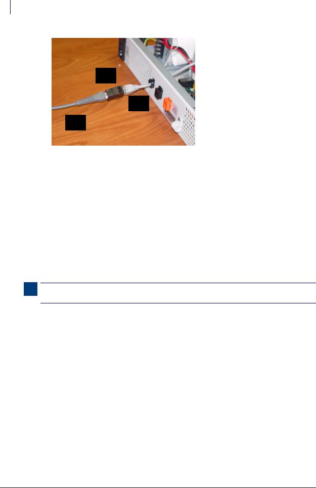
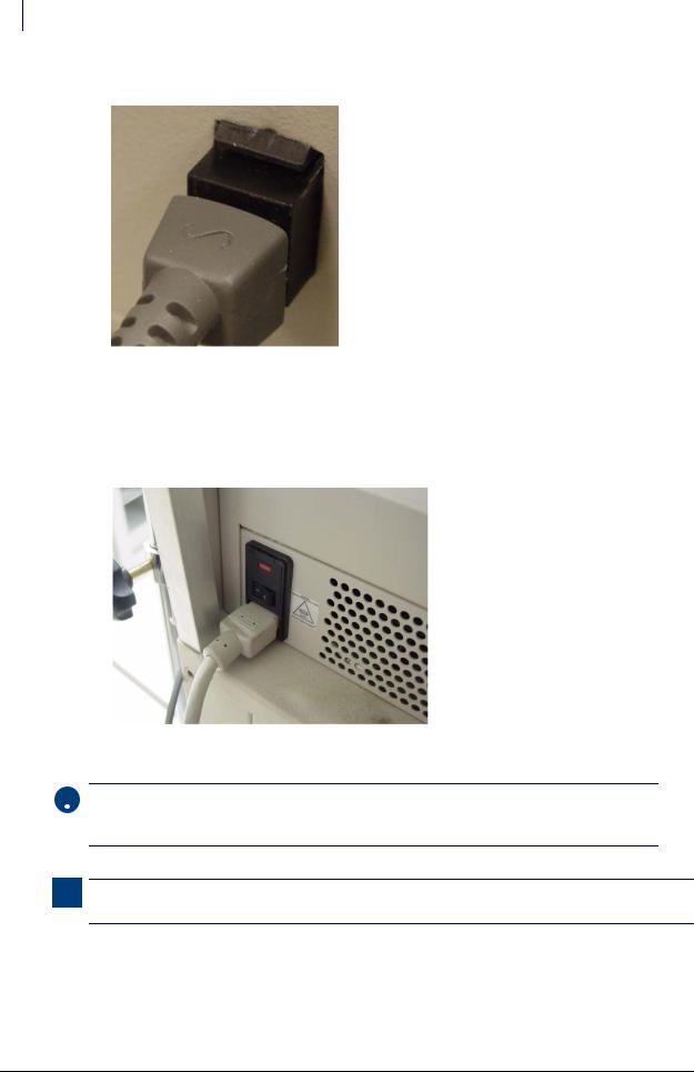
1. Connect the power cord and power up the cabinet.
Figure 1-17. Turning on the power
 Important: The scanner is programmed prior to initial use. Should the scanner fail to recognize supported bar code types, reprogramming may be required. For more scanner-specific information, see the Symbol documentation shipped with the scanner.
Note: Depending on the cabinet’s operating system version, it may be necessary to install files or drivers associated with the USB Human Interface Devices.
2.Test the scanner by reading a test bar code twice while the logon screen is displayed. The window changes to an error message after the first read, then returns to the login screen on the second read. The bar code information should be listed in the User ID box.
3.Perform the software implementation procedures. See “Implementation” on page 1-53.
SafetyStock Technical Guide/67-3025 Rev C |
© 2008 Omnicell, Inc. |
SafetyStock 1-13
Hardware Installation
OmniSupplier
The following instructions apply to SafetyStock scanner installation for OmniSupplier Color Touch cabinets, using manufacturing kit #20-6033.
Required Tools
T10 torx driver
9/64 Allen wrench
Pliers
ESD wristband
Cam lock key #2036
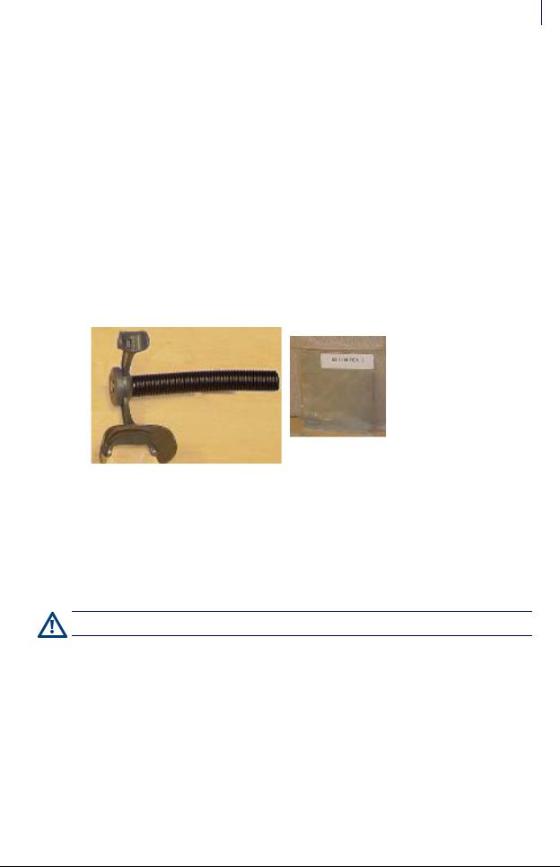
Required Kit/Parts
The OmniSupplier requires kit #20-6033, which contains: kit #12-1266 (items shown on
“Required Kit/Parts” on page 1-3), #14-1245 (items shown below).
Figure 1-18. Gooseneck assembly and back plate
Cabinet Preparation
1.Perform a graceful shutdown of the cabinet software, then power down the cabinet and disconnect the power cord.
2.Remove the screws securing the PC box to the frame, and slide the PC box forward.
3.Using key #2036, unlock and remove the PC box cover.
Caution: Put on an ESD wristband and secure it to a ground before working on the PC box.
© 2008 Omnicell, Inc. |
SafetyStock Technical Guide/67-3025 Rev C |
1-14 SafetyStock
Hardware Installation
4.Use the T-10 Torx driver to remove the four 6-32 pan head screws which secure the connector panel plate to the rear of the PC box.
Figure 1-19. Removing the connector plate screws
5.Punch out the cutout on the kit’s connector panel plate (#53-1109) or the existing plate if applicable.
6.Install the connector panel plate (from the kit or the existing plate) with the cutout removed with four 6-32 pan head screws and the T-10 Torx driver.
7.Insert the RJ-12 coupler (#82-6071) into the back plate from inside the PC box. The larger section faces inside the electronics tray. The connector’s outer connector has the locking tab space facing down. The connector’s inner connector has the locking tab space facing up.
Figure 1-20. Insert RJ-12 coupler
SafetyStock Technical Guide/67-3025 Rev C |
© 2008 Omnicell, Inc. |
SafetyStock 1-15
Hardware Installation
Cable Connections
1.Disconnect the RJ-12 coupler from the conversion kit (#12-1266). The adapter cable (#42-
1303) remains connected to the Synapse adapter and the USB cable (#88-0022). The scanner cable (#88-6026) remains connected to the scanner (#70-6048).
#88-6026
#42-1303
#82-6071
Figure 1-21. RJ-12 coupler from kit
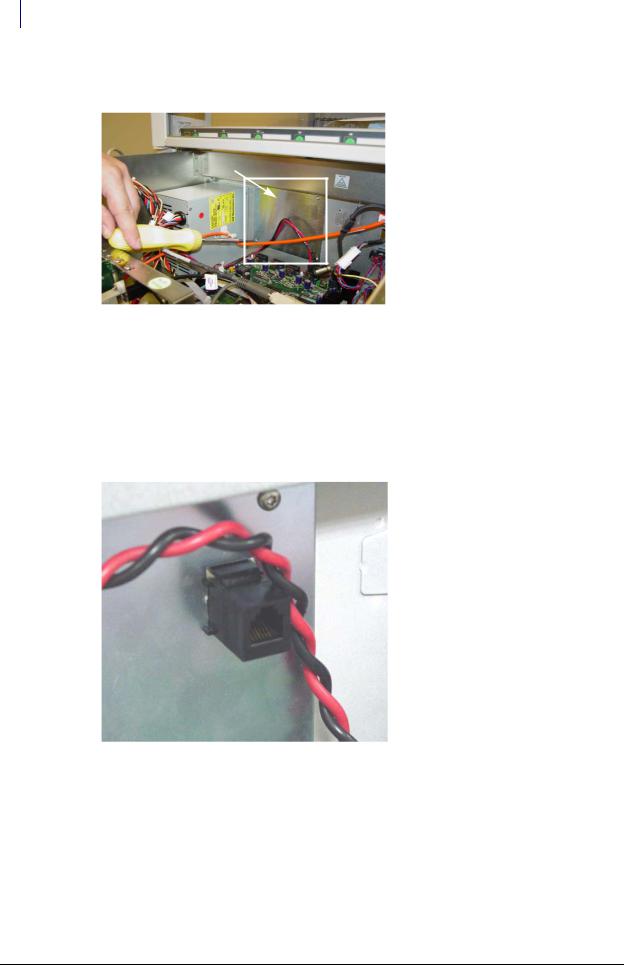
2. Connect the USB Synapse cable (#88-0022) from the kit to the mother board.
 Note: It may be necessary to move any existing USB cables to the lower USB port for ease of installment.
Figure 1-22. USB Synapse cable
3. Properly route the cable. Use cable ties to secure cables as needed.
© 2008 Omnicell, Inc. |
SafetyStock Technical Guide/67-3025 Rev C |
1-16 SafetyStock
Hardware Installation
4. Route and connect the adapter cable (#42-1303) to the RJ-12 coupler inside the PC box.
Figure 1-23. Connecting the cable to the coupler inside the PC box; completing cable routing in PC box
5.Replace the PC box lid, then slide in and re-secure the PC box.
6.Remove the ESD wristband.
Scanner Connection
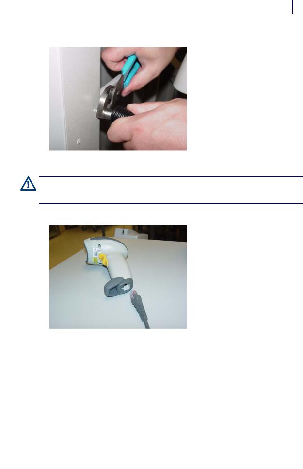
1.Use the 9/64 Allen wrench to remove the front screw (5/16 button head) from the transport handle on the side of the cabinet.
Figure 1-24. Removing the transport handle screw
2. Screw the gooseneck cradle (#15-6002) into the transport handle until it is secure.
SafetyStock Technical Guide/67-3025 Rev C |
© 2008 Omnicell, Inc. |
SafetyStock 1-17
Hardware Installation
3. Pull back the accordion sleeve and tighten the gooseneck base with pliers.
Figure 1-25. Tightening the gooseneck base
Caution: The scanner cable must be connected correctly or the scanner will not work. The 10-pin RJ 45 sized end of the scanner cable connects in the scanner handle. The 6-pin RJ-12 sized end of the scanner cable connects to the RJ-12 connector in the back plate.
4. Connect the scanner cable (#88-6026) to the scanner (#70-6048) at the base of the handle.
Figure 1-26. Connecting the scanner cable to the scanner
© 2008 Omnicell, Inc. |
SafetyStock Technical Guide/67-3025 Rev C |

1-18 SafetyStock
Hardware Installation
5. Connect the new scanner cable (#88-6026) into the RJ-12 coupler on the back plate.
Figure 1-27. Connect scanner cable to RJ-12 coupler
6. Attach the scanner label/sticker (#65-1057) near the coupler.
Final Procedures
1. Reconnect power and reboot the cabinet software.
 Important: The scanner is programmed prior to initial use. Should the scanner fail to recognize supported bar code types, reprogramming may be required. For more scanner-specific information, see the Symbol documentation shipped with the scanner.
Note: Depending on the cabinet’s operating system version, it may be necessary to install files or drivers associated with the USB Human Interface Devices.
2.Test the scanner by reading a test bar code twice while the logon screen is displayed. The window changes to an error message after the first read, then returns to the login screen on the second read. The bar code information should be listed in the User ID box.
3.Perform the software implementation procedures. See “Implementation” on page 1-53.
OmniCenter/Implant Tracking/OCRA Machines/SecureVault
The following instructions apply to:
OmniCenter servers and OCRA machines, (kit #20-6031)
Implant Tracking (kit #12-6006)
SecureVault (kit #20-6039)
Required Tools
None
SafetyStock Technical Guide/67-3025 Rev C |
© 2008 Omnicell, Inc. |
SafetyStock 1-19
Hardware Installation
Required Kit/Parts
OmniCenter Servers and OCRA machines use kit #20-6031. See “Required Kit/Parts” on page 1-3.
Scanner
Stand #70-6049
Scanner #70-6048
|
|
Scanner |
Scanner |
|
USB Cable |
Document |
|
#88-6152 |
#60-3003 |
|
|
|
|
|
Figure 1-28. Scanner kit items for OmniCenter server and OCRA machines
Implant Tracking uses kit #12-6006.
Figure 1-29. Mount bracket and wall mount
SecureVault uses kit #20-6039. The items in this kit are similar to those in kit #14-1243.
Procedure
1. Perform a graceful shutdown of the OmniCenter computer.
© 2008 Omnicell, Inc. |
SafetyStock Technical Guide/67-3025 Rev C |
1-20 SafetyStock
Hardware Installation
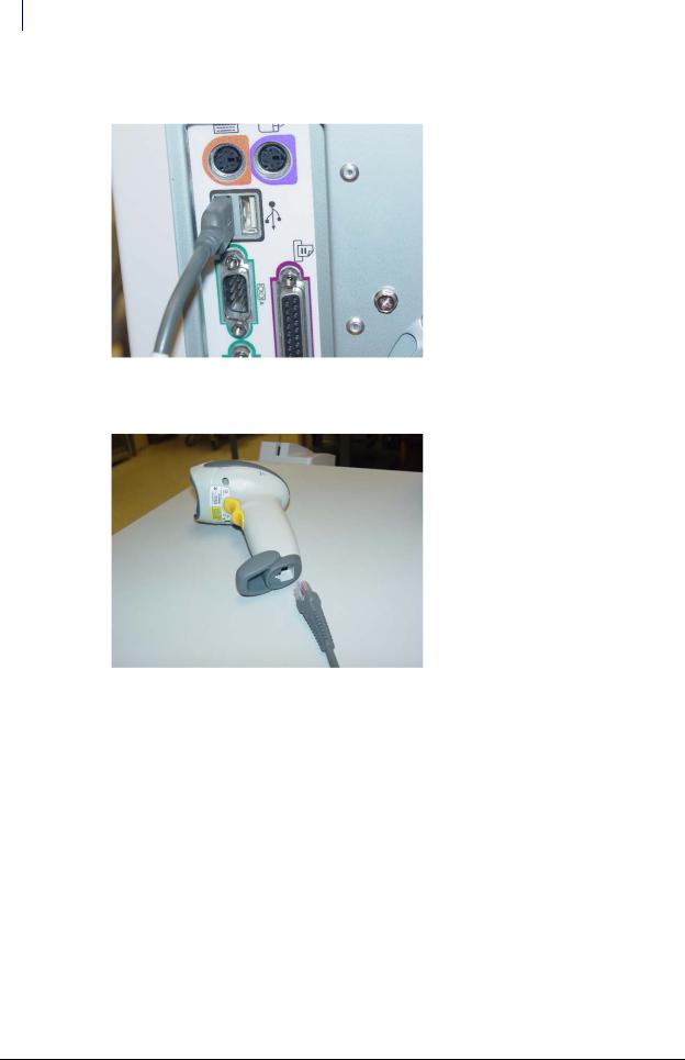
2.Connect the USB end of the scanner cable (#88-6152) into the USB slot in back of the computer.
Figure 1-30. Connecting the scanner cable to the keyboard port
3. Connect the other end of the scanner cable (#88-6152) into the base of the scanner handle.
Figure 1-31. Connecting the scanner cable into the scanner
4. Place the scanner stand (#70-6049) near the OmniCenter.
SafetyStock Technical Guide/67-3025 Rev C |
© 2008 Omnicell, Inc. |

SafetyStock 1-21
Software Functionality
5. Place the scanner (#70-6048) in the stand.
Figure 1-32. Placing the scanner into the stand
6. Turn on the computer power.
 Important: The scanner is programmed prior to initial use. Should the scanner fail to recognize supported bar code types, reprogramming may be required. For more scanner-specific information, see the Symbol documentation shipped with the scanner.
Note: Depending on the cabinet’s operating system version, it may be necessary to install files or drivers associated with the USB Human Interface Devices.
7.Test the scanner by reading a test bar code twice while the logon screen is displayed. The window changes to an error message after the first read, then returns to the login screen on the second read. The bar code information should be listed in the User ID box.
8.Perform the software implementation procedures. Refer to “Implementation” on page 1-53.
Software Functionality
OmniCenter
In order to support the SafetyStock feature—for both WorkflowRx and non-WorkflowRx customers—a number of changes have been made at the OmniCenter. These include modifications to the Administration tab, Restock tab, Database tab Items table, and OmniSupplier and Transactions tables, as well as new and modified reports.
Administration Tab Modifications
Administration tab modifications include the ability to print Bin Confirmation Labels
(Administration > OmniSuppliers), and the addition of a Restock Configuration Setup section (Administration > Setup).
© 2008 Omnicell, Inc. |
SafetyStock Technical Guide/67-3025 Rev C |
1-22 SafetyStock
Software Functionality
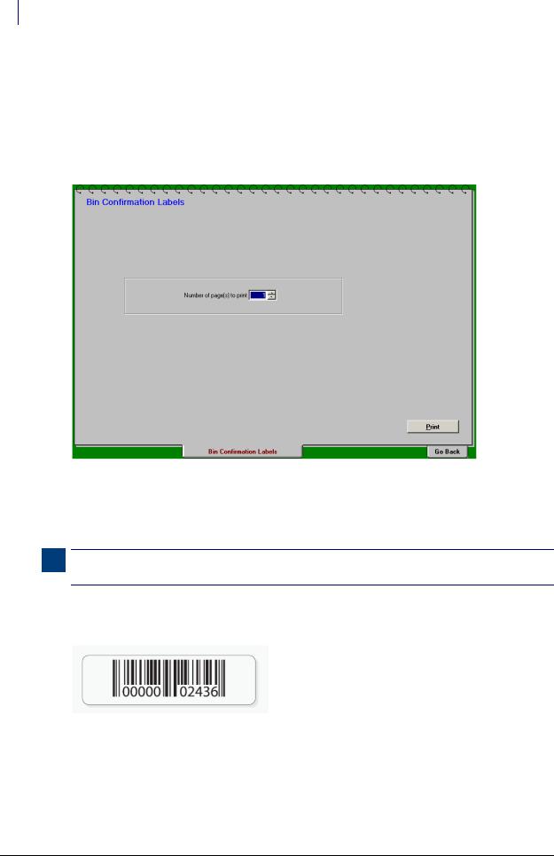
Printing Bin Confirmation Labels A Bin Confirmation Labels option has been added to the
Administration tab, OmniSuppliers Administration type. This allows users to generate and print bin bar code labels, for use with the bin confirmation restock function. Bin confirmation labels are formatted for Avery 5167 or 5267 labels and print to a standard laser printer (8 1/2” x 11” sheet, White, Laser, Permanent-Adhesive; 80 labels per sheet.).
To print one or more sheets of labels, the user selects the Bin Confirmation Labels option, types in the number of pages desired, then clicks Print.
Figure 1-33. Administration Tab, OmniSupplier Admin Type—Print Bin Confirmation Labels
The labels are printed in sequential order. If labels have been printed in the past, numbering for subsequent jobs start where the last print job left off. The OmniCenter retains this information, to prevent duplication of bin bar codes.
Note: ID numbers are generated sequentially, starting from 1 and ending at 2,147,483,647. If the maximum number is reached the sequence starts again at 1.
Once printed, labels are placed in the desired bins. Bin association is performed via the Color
Touch software and scanner. See sample label below.
Figure 1-34. Sample bin confirmation label
SafetyStock Technical Guide/67-3025 Rev C |
© 2008 Omnicell, Inc. |
SafetyStock 1-23
Software Functionality
Restock Configuration Setup A Restock Configuration Setup screen has been added to the Administration tab, Setup Administration type. Restock Configuration Setup contains three screens:
Restock Printing
Report Setup
Miscellaneous Restock Settings
Note: The detailed explanation of the Restock Configuration Setup provided here is only for fields with a new or revised function. For more information on restock functions, see the Omnicell 9000 Technical Release Guide (P/N 60-0077, Rev. C or higher) and Omnicell 9000 Color Touch 5.6 User Guide (P/N 60-0095).
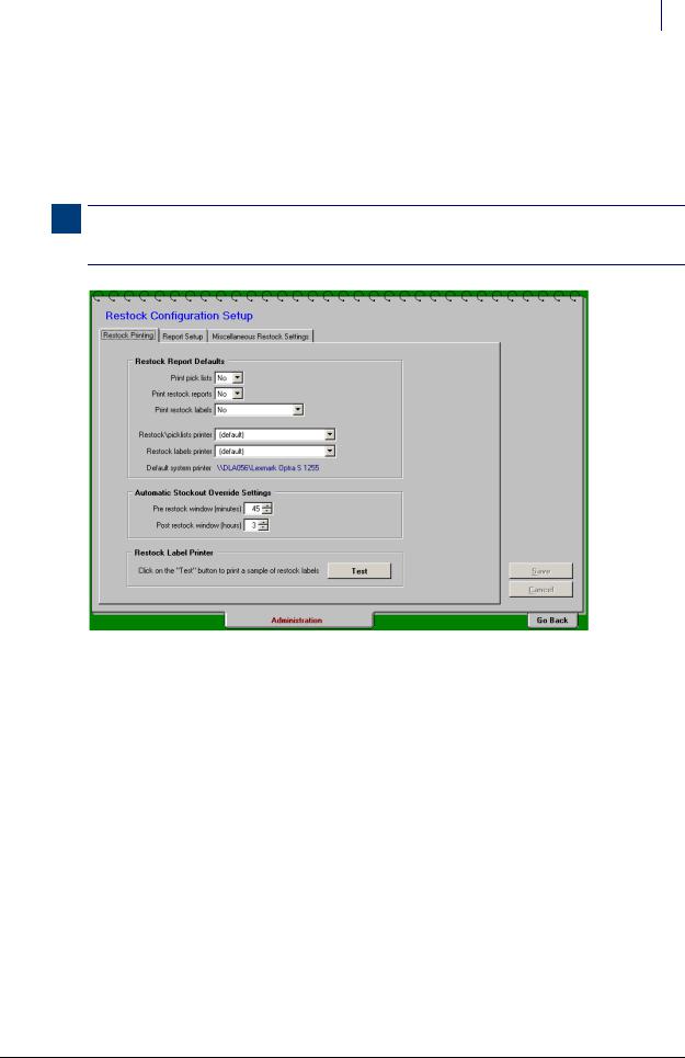
Figure 1-35. Administration Tab, Setup Admin Type—Restock Configuration Setup Screens
Restock Printing Screen The Restock Printing screen (see Figure 1-35) allows the user to control the following settings:
Restock Report Defaults
Print pick lists (Yes/No)
Print restock reports (Yes/No)
Print restock labels (Yes/No/SafetyStock Items Only)
Restock/picklists printer
Restock labels printer
Default system printer (read-only field)
Automatic Stockout Override Settings
Pre-restock window, in minutes (0-720)
Post-restock window, in hours (0-24)
Restock Label Printer (Test button)
For user to test the SafetyStock label printer
© 2008 Omnicell, Inc. |
SafetyStock Technical Guide/67-3025 Rev C |

1-24 SafetyStock
Software Functionality
The Restock Report Defaults section has been added to allow users to specify whether or not to print pick lists, restock reports and/or restock labels. The Print restock labels option determines if restock labels will be printed, by default, when generating restocks, and if so, whether to print labels only for SafetyStock items. If this option is set to Yes or SafetyStock Items Only, restock labels are generated, by default, at the designated SATO label printer. If SafetyStock Items Only is selected, labels are only printed for items set to Confirm Restock: ...scan required in the Items database.
The Automatic Stockout Override Settings allow the user to specify the time periods, prior to normal restock generation and fulfillment, that Automatic Stockout restock generation should not occur. The Prerestock window setting determines the amount of time prior to normal restock generation that Automatic Restock triggers will be ignored. The Post-restock window setting determines the amount of time after normal restock generation that Automatic Restock triggers will be ignored.
The Restock/picklists printer and Restock labels printer fields allow the user to specify the default printer for restock reports and picklists, and the default printer for restock labels. The Default system printer field is read-only; it displays the designated OmniCenter/system printer.
Report Setup Screen The Report Setup screen allows the user to control the following settings:
Restock Report (sort order/report type defaults)
Restock report
Standard option provides options by item with on-order info or Standard (by bin) Custom option selects a custom report
Order restock list
By Omni Bin/Stock Bin/item ID/Item Name
Pick List (sort order/report type defaults)
Pick list report
Standard option includes Standard (by Source); By Omni; By source w/costs; By source w/ item bar codes; By source w/par
Custom option selects a custom report
Order pick list
By Bin Location; Item ID; Item Name
Show quantity
By Unit of Stocking; Unit of Issue
Split
By Omni; Consolidated (read-only field controlled by Pick List Report setting)
Miscellaneous Restock Settings Screen The Miscellaneous Restock Settings screen allows the user to control the following settings:
Generate restocks (Yes/No) (Yes if selected; No if de-selected)
Days to accumulate restock quantities, in days (0-365)
Restock critically low items to (Par/Reorder Point)
Restock Tab Modifications
The Restock tab now features separate screens for restock by route, by omni (cabinet), and by item (Selective Restock), as well as for reprints. It also has numerous other user interface enhancements.
SafetyStock Technical Guide/67-3025 Rev C |
© 2008 Omnicell, Inc. |

SafetyStock 1-25
Software Functionality
Note: Detailed explanation is provided here only for fields related to new features (i.e. SafetyStock, Automatic Stockout, etc.). For more information on restock functions, see the Omnicell 9000 Technical Release Guide (P/N 60-0077, Rev. C or higher) and Omnicell 9000 Color Touch 5.6 User Guide (P/N 60-0095).
The feature enhancements specifically related to and/or useful for SafetyStock include:
The addition of a Restock By Item option (Selective Restock).
The addition of a Print Labels option, including the ability to limit printing to SafetyStock items. The Labels option is used to print restock labels to the SATO printer.
The Reprint option provides the ability to reprint restocks for selected items (see “Reprint Restock” on page 1-29).
General User Interface Changes The restock screens now function like other OmniCenter screens. Following are some of the general user interface changes:
Note: A detailed explanation of Restock Configuration Setup is provided here only for fields with new or revised functionality. For more information on restock functions, see the Omnicell 9000 Technical Release Guide (P/N 60-0077, Rev. C or higher) and Omnicell 9000 Color Touch 5.6 User Guide (P/N 60-0095).
Sort lists in ascending or descending order by clicking the header columns (marked with an up/down arrow).
All and Clear All functions help manage lists.
User selected items are retained when users leave, then return to the page. Once the restock is generated, the selections are cleared automatically.
Additionally, each Restock option page includes the ability to select/de-select Print options.
Although the default settings for these fields are controlled by the Restock Configuration Settings
(Administration tab, Setup Admin Type), the user can choose whether or not to print picklists, restock reports and/or labels as needed.
© 2008 Omnicell, Inc. |
SafetyStock Technical Guide/67-3025 Rev C |

1-26 SafetyStock
Software Functionality
Restock By Route
Figure 1-36. Restock Tab—Restock By Route (default view)
Restock By Omni
Figure 1-37. Restock Tab—Restock By Omni
Restock By Item (Selective Restock) The Restock By Item option, or selective restock, allows users to generate a restock at the OmniCenter for specific items, apart from the normal restock process. To do so, the user selects the Restock tab, Restock By Item option, then clicks Add to search for and add individual items to the list.
SafetyStock Technical Guide/67-3025 Rev C |
© 2008 Omnicell, Inc. |
Loading...