


 Loading...
OmniRx Service Guide
67-2023 Rev D

This guide is CONFIDENTIAL and designed only for Omnicell Technical personnel and/or designated representatives.
This guide and accompanying software and/or hardware described in it are protected under copyright laws and may not be copied, wholly or in part, without the express written consent of Omnicell, Inc. The same proprietary and copyright notices must be attached to any permitted copies as were attached to the original documents.
Omnicell, Inc.
1201 Charleston Road Mountain View, CA 94043 (650) 251-6100 www.omnicell.com
Omnicell and the Omnicell design mark, OmniBuyer, OmniCenter, OmniRx, OmniSupplier, SafetyMed, SafetyPak, SafetyStock, and Sure-Med are registered trademarks. Anesthesia TT, Anesthesia Workstation, Anywhere RN, Executive Advisor, Flexbin, Medication Surveillance, OmniDispenser, OmniLinkRx, OmniScanner, OmniTrack, Omni TT, Open Touch, OptiFlex, OptiFlex MobileTrack, Point-to-Point Medication Safety, SecureVault, See & Touch, SinglePointe, TempCheck, Touch & Go, VSuite, and WorkflowRx are trademarks of Omnicell, Inc. in the United States and internationally. All other trademarks and trade names are the property of their respective owners
Copyright 2010 Omnicell, Inc. All rights reserved.
OmniRx Service Guide/67-2023 Rev D |
© 2010 Omnicell, Inc. |

iii
Table of Contents
Electronics Sled . . . . . . . . . . . . . . . . . . . . . . . . . . . . . . . . . . . . . . . . . . . . . . . . . . . . . . . . . . . . . . 1-1
Tools List . . . . . . . . . . . . . . . . . . . . . . . . . . . . . . . . . . . . . . . . . . . . . . . . . . . . . . . . . . . . . . . . . . . . 1-1
General Shutdown. . . . . . . . . . . . . . . . . . . . . . . . . . . . . . . . . . . . . . . . . . . . . . . . . . . . . . . . . . . . 1-1
LCD Screen Removal . . . . . . . . . . . . . . . . . . . . . . . . . . . . . . . . . . . . . . . . . . . . . . . . . . . . . . . . . 1-2
Speaker Removal . . . . . . . . . . . . . . . . . . . . . . . . . . . . . . . . . . . . . . . . . . . . . . . . . . . . . . . . . . . . . 1-3
Printer Removal. . . . . . . . . . . . . . . . . . . . . . . . . . . . . . . . . . . . . . . . . . . . . . . . . . . . . . . . . . . . . . 1-4
Seiko Printer. . . . . . . . . . . . . . . . . . . . . . . . . . . . . . . . . . . . . . . . . . . . . . . . . . . . . . . . . . . . . . 1-4
APS Printer. . . . . . . . . . . . . . . . . . . . . . . . . . . . . . . . . . . . . . . . . . . . . . . . . . . . . . . . . . . . . . . 1-7
Keyboard Service . . . . . . . . . . . . . . . . . . . . . . . . . . . . . . . . . . . . . . . . . . . . . . . . . . . . . . . . . . . . 1-10
PS/2 Keyboard . . . . . . . . . . . . . . . . . . . . . . . . . . . . . . . . . . . . . . . . . . . . . . . . . . . . . . . . . . . 1-11
USB Keyboard . . . . . . . . . . . . . . . . . . . . . . . . . . . . . . . . . . . . . . . . . . . . . . . . . . . . . . . . . . . 1-13
PC Tray Upgrade . . . . . . . . . . . . . . . . . . . . . . . . . . . . . . . . . . . . . . . . . . . . . . . . . . . . . . . . . . . . 1-14
PowerCom2 Tray . . . . . . . . . . . . . . . . . . . . . . . . . . . . . . . . . . . . . . . . . . . . . . . . . . . . . . . . 1-14
PowerCom3 Tray . . . . . . . . . . . . . . . . . . . . . . . . . . . . . . . . . . . . . . . . . . . . . . . . . . . . . . . . 1-16
Standardization Changes. . . . . . . . . . . . . . . . . . . . . . . . . . . . . . . . . . . . . . . . . . . . . . . . . . . . . 1-21
Final Steps . . . . . . . . . . . . . . . . . . . . . . . . . . . . . . . . . . . . . . . . . . . . . . . . . . . . . . . . . . . . . . . . . . 1-21
Frames and Wireways . . . . . . . . . . . . . . . . . . . . . . . . . . . . . . . . . . . . . . . . . . . . . . . . . . . . . . . . 2-1
Wireway Removal . . . . . . . . . . . . . . . . . . . . . . . . . . . . . . . . . . . . . . . . . . . . . . . . . . . . . . . . . . . . 2-1
Manual Override Cable Service . . . . . . . . . . . . . . . . . . . . . . . . . . . . . . . . . . . . . . . . . . . . . . . . 2-4
Removal . . . . . . . . . . . . . . . . . . . . . . . . . . . . . . . . . . . . . . . . . . . . . . . . . . . . . . . . . . . . . . . . . 2-4
Replacement. . . . . . . . . . . . . . . . . . . . . . . . . . . . . . . . . . . . . . . . . . . . . . . . . . . . . . . . . . . . . . 2-7
Drawers . . . . . . . . . . . . . . . . . . . . . . . . . . . . . . . . . . . . . . . . . . . . . . . . . . . . . . . . . . . . . . . . . . . . . 3-1
Overview . . . . . . . . . . . . . . . . . . . . . . . . . . . . . . . . . . . . . . . . . . . . . . . . . . . . . . . . . . . . . . . . . . . . 3-1
Tools List . . . . . . . . . . . . . . . . . . . . . . . . . . . . . . . . . . . . . . . . . . . . . . . . . . . . . . . . . . . . . . . . . . . . 3-1
Matrix Drawers . . . . . . . . . . . . . . . . . . . . . . . . . . . . . . . . . . . . . . . . . . . . . . . . . . . . . . . . . . . . . . 3-2
Bin Configuration . . . . . . . . . . . . . . . . . . . . . . . . . . . . . . . . . . . . . . . . . . . . . . . . . . . . . . . . . 3-2
Unlit Matrix Drawers . . . . . . . . . . . . . . . . . . . . . . . . . . . . . . . . . . . . . . . . . . . . . . . . . . 3-2
Lit Matrix Drawers . . . . . . . . . . . . . . . . . . . . . . . . . . . . . . . . . . . . . . . . . . . . . . . . . . . . 3-3
Double-Deep Matrix Drawer . . . . . . . . . . . . . . . . . . . . . . . . . . . . . . . . . . . . . . . . . . . . . . . 3-3
Matrix Drawers Labels . . . . . . . . . . . . . . . . . . . . . . . . . . . . . . . . . . . . . . . . . . . . . . . . . . . . . 3-4
Supply Drawer Installation . . . . . . . . . . . . . . . . . . . . . . . . . . . . . . . . . . . . . . . . . . . . . . . . . . . . 3-5
Pharmacy Drawer Installation . . . . . . . . . . . . . . . . . . . . . . . . . . . . . . . . . . . . . . . . . . . . . . . . . 3-5
Pharmacy Drawer Removal. . . . . . . . . . . . . . . . . . . . . . . . . . . . . . . . . . . . . . . . . . . . . . . . . . . . 3-8
Appendix A: Part List . . . . . . . . . . . . . . . . . . . . . . . . . . . . . . . . . . . . . . . . . . . . . . . . . . . . . . . . |
A-1 |
Index. . . . . . . . . . . . . . . . . . . . . . . . . . . . . . . . . . . . . . . . . . . . . . . . . . . . . . . . . . . . . . . . . . . . Index-1
© 2010 Omnicell, Inc. |
OmniRx Service Guide/67-2023 Rev D |

iv Table of Contents
Documentation Feedback . . . . . . . . . . . . . . . . . . . . . . . . . . . . . . . . . . . . . . . . . . . . . Feedback-1
OmniRx Service Guide/67-2023 Rev D |
© 2010 Omnicell, Inc. |
1-1
Electronics Sled
This chapter provides detailed instructions to remove specific parts in the electronics sled. To replace the item, reverse the removal steps with the new part.
The whole console is replaced when changing out the Seiko printer and PS/2 keyboard for the
APS printer and USB keyboard (with separate numeric pad) when spares are used up.
Tools List
The following tools are required to install the electronics tray:
T8 Torx Driver
T10 Torx Driver
T15 Torx Driver
9/64” Allen wrench
Standard adjustable wrench
General Shutdown
Perform shutdown procedures before doing any service.
1.Perform a graceful shutdown of the electronics sled.
2.Unplug the power cable to the OmniRx.
3.Unlock the console with the #2036 key.
4.Lift the console from the rear of the OmniRx, then prop it up.
Caution: Use an ESD wrist band while working inside the sled.
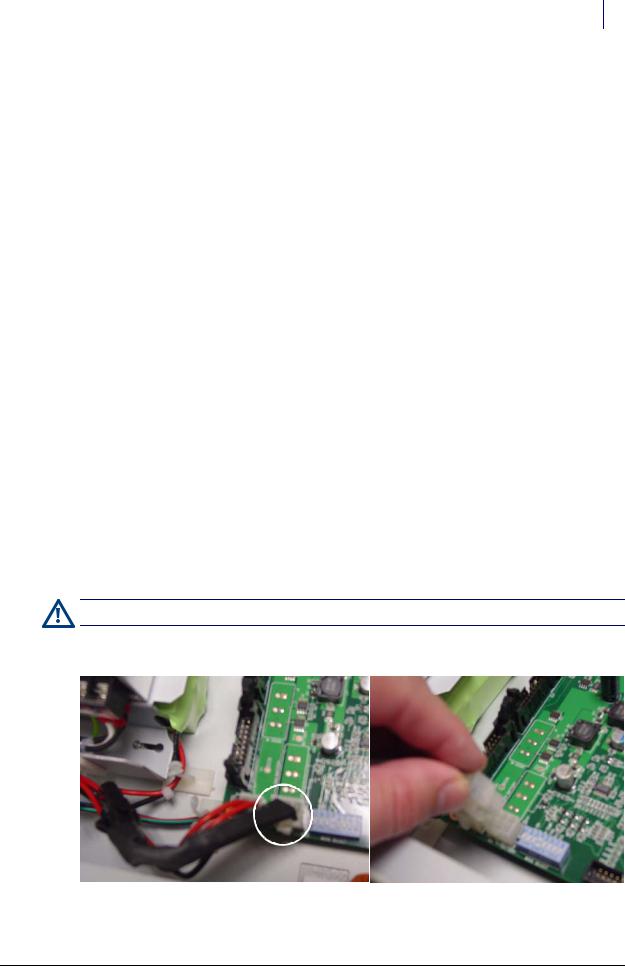
5. Disconnect the black battery cable.
Figure 1-1. Battery cable
© 2010 Omnicell, Inc. |
OmniRx Service Guide/67-2023 Rev D |
1-2 Electronics Sled
LCD Screen Removal
LCD Screen Removal
1.Lower the console into the closed position.
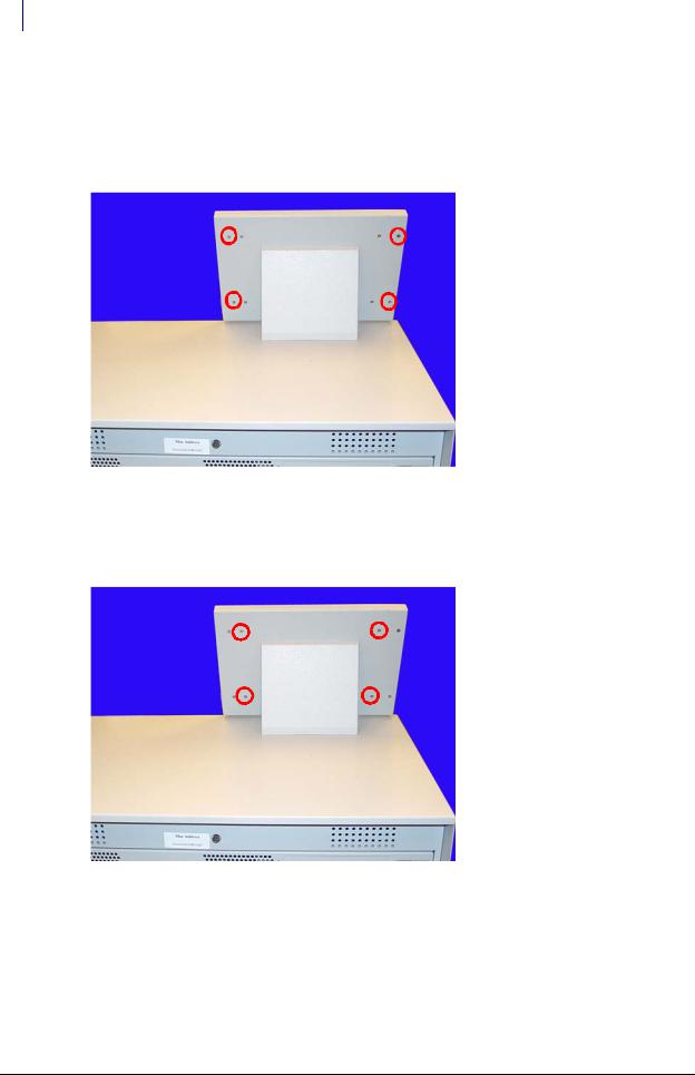
2.Remove the four outer screws that secure the LCD bezel to the console using a Torx T10 screwdriver.
Figure 1-2. Remove the four outer screws
3.Remove the bezel.
4.Remove the four inner screws at the back of the bezel. Hold onto the front of the LCD screen while removing the screws so that the assembly does not fall.
Figure 1-3. Remove the four inner screws
5.Tilt the LCD assembly forward and disconnect the cables from the back of the LCD assembly.
a.Disconnect the inverter to power cable.
b.Disconnect the flat panel cable.
6.Remove the LCD assembly from the LCD housing.
OmniRx Service Guide/67-2023 Rev D |
© 2010 Omnicell, Inc. |
Electronics Sled 1-3
Speaker Removal
Speaker Removal
1.Lift the console from the rear and prop it up if it is not already open.
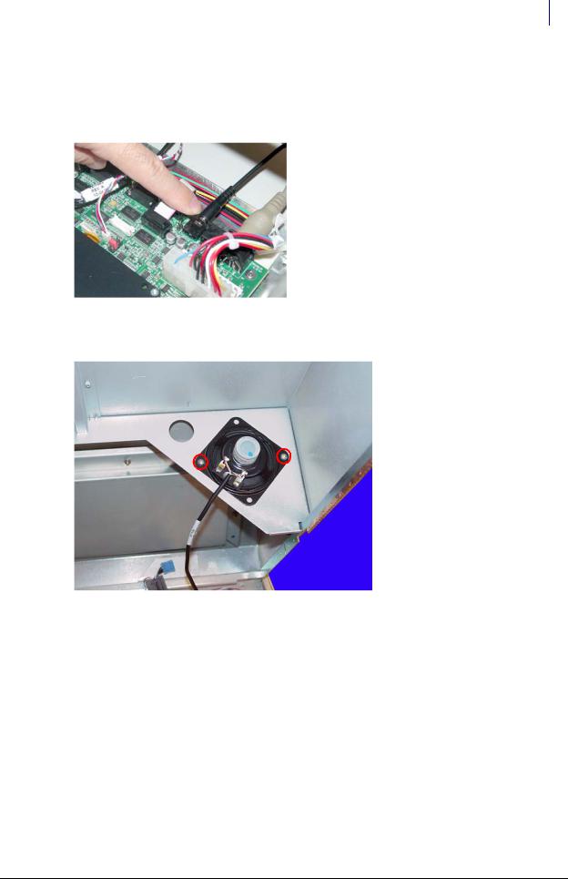
2.Disconnect the speaker cable from the motherboard.
Figure 1-4. Disconnect the speaker cable from the motherboard
3. Remove the two screws that hold the speaker in place using a Torx T10 screwdriver.
Figure 1-5. Remove the speaker
4. Disconnect the speaker from the console top.
© 2010 Omnicell, Inc. |
OmniRx Service Guide/67-2023 Rev D |
1-4 Electronics Sled
Printer Removal
Printer Removal
Seiko Printer
1.Lower the console into the closed position.
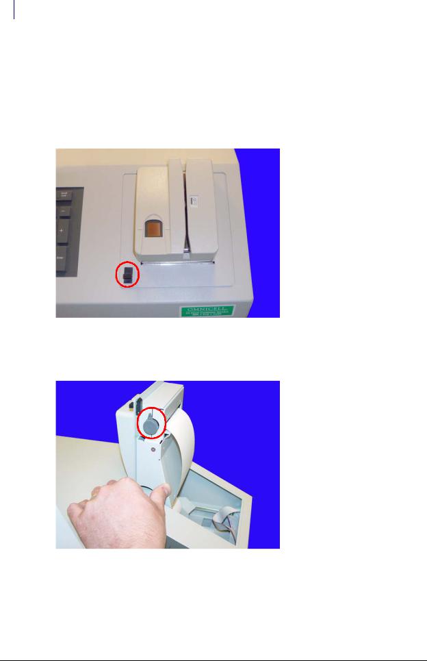
2.Open the printer cover by pushing the black release mechanism toward the rear of the machine and lifting the cover.
Figure 1-6. Open the printer cover
3.Remove the paper from the printer.
4.Push the platen lever to the left to the disengaged position.
Figure 1-7. Turn the platen lever
OmniRx Service Guide/67-2023 Rev D |
© 2010 Omnicell, Inc. |
Electronics Sled 1-5
Printer Removal
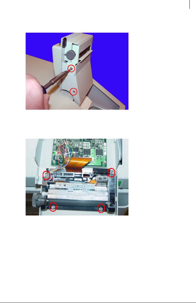
5. Remove the four screws (two on each side) that secure the printer assembly to the cover.
Figure 1-8. Remove the printer assembly screws
6.Remove the printer assembly.
7.Remove the four screws that secure the lower assembly to the frame.
Figure 1-9. Remove the lower assembly screws
© 2010 Omnicell, Inc. |
OmniRx Service Guide/67-2023 Rev D |
1-6 Electronics Sled
Printer Removal
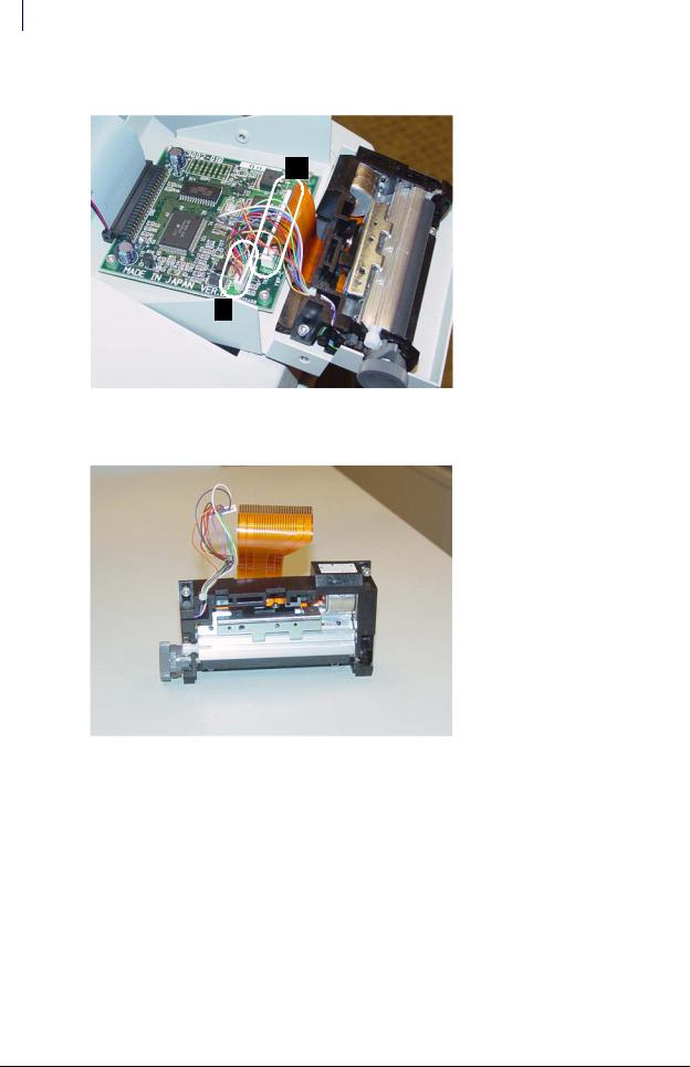
8. Disconnect the printer ribbon cable and the printer data cables from the printer PC Board.
A
B
Figure 1-10. Remove the printer cables
9. Remove the printer.
Figure 1-11. Remove the printer
OmniRx Service Guide/67-2023 Rev D |
© 2010 Omnicell, Inc. |
Electronics Sled 1-7
Printer Removal
10. Remove the four screws that secure the PC card to the frame.
Figure 1-12. Remove printer PC card screws
11. Lift the card off the frame slightly, then remove the printer ribbon cable.
APS Printer
This service procedure is similar to the Seiko printer.
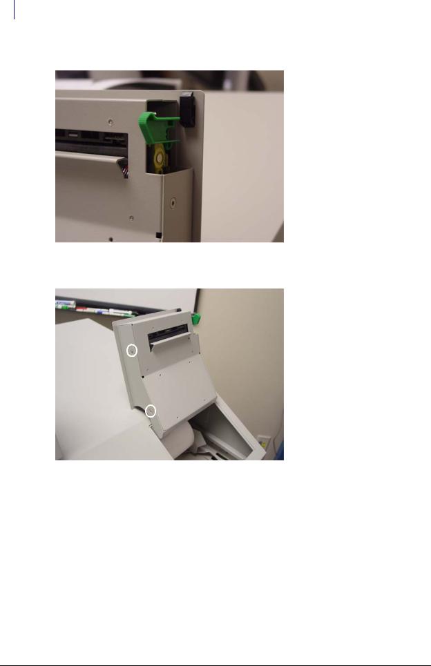
1.Open the printer cover by pushing the black release mechanism toward the rear of the machine and lifting the cover.
Figure 1-13. Open the printer cover
2. Remove the paper from the printer.
© 2010 Omnicell, Inc. |
OmniRx Service Guide/67-2023 Rev D |
1-8 Electronics Sled
Printer Removal
3. Lift the green platen lever on the right side to the disengaged position.
Figure 1-14. Lift the platen lever
4. Remove the four screws (two on each side) that secure the printer assembly to the cover.
Figure 1-15. Remove the Screws Securing the Printer Assembly
5. Remove the printer assembly.
OmniRx Service Guide/67-2023 Rev D |
© 2010 Omnicell, Inc. |
Electronics Sled 1-9
Printer Removal
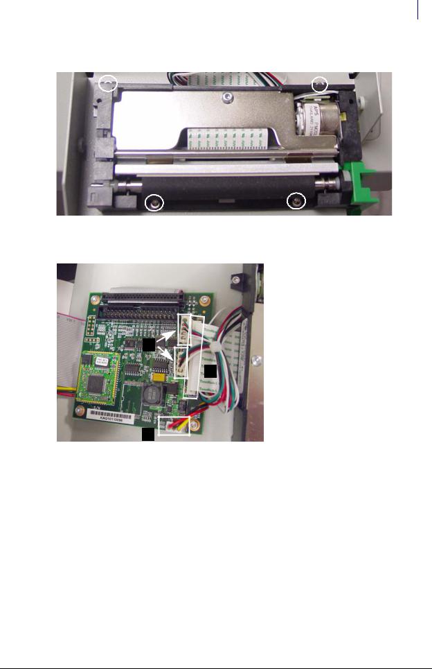
6. Remove the four screws that secure the lower assembly to the frame.
Figure 1-16. Remove the lower assembly screws (top screws partially hidden)
7. Disconnect the four printer cables from the printer PC Board.
B
A
C
Figure 1-17. Remove the printer cables: (a) ribbon cable (b) 2 data cables (c) power cable)
© 2010 Omnicell, Inc. |
OmniRx Service Guide/67-2023 Rev D |

1-10 Electronics Sled
Keyboard Service
8. Remove the printer.
Figure 1-18. Remove the printer
9. Remove the four screws that secure the PC card to the frame.
Figure 1-19. Remove the printer PC card screws
10. Lift the card off the frame slightly, then remove the printer ribbon cable.
Keyboard Service
1.Disconnect all console cables.
2.Remove the console and set it upside down in a work area.
OmniRx Service Guide/67-2023 Rev D |
© 2010 Omnicell, Inc. |

Electronics Sled 1-11
Keyboard Service
PS/2 Keyboard
1. Remove the 14 nuts that secure the keyboard cover to the tray.
Figure 1-20. Remove the nuts that secure the keyboard cover to the tray
2. Remove the keyboard cover.
Figure 1-21. Remove the keyboard cover
3. Remove the keyboard from the tray.
© 2010 Omnicell, Inc. |
OmniRx Service Guide/67-2023 Rev D |

1-12 Electronics Sled
Keyboard Service
4.Hold the keypad with the elastomer facing up and gently pull the elastomer up and off the keyboard.
Figure 1-22. Pull the elastomer up and off the keyboard
5.Gently place the new elastomer onto the keyboard and push the rubber tabs through the holes on the keyboard.
6.Keeping the keypad upright, reach underneath the keyboard and gently pull the tabs until the elastomer rests snugly on the keyboard.
Note: To prevent ripples in the elastomer, pull the tabs through going left to right, right to left, bottom to top or top to bottom. Do not pull the tabs through in a random order or in a circular pattern.
7.Remove any bubble or ripples in the elastomer and then place the new keypad and elastomer back into place on the tray.
8.Replace the keyboard cover.
9.Replace the screws that secure the keyboard cover to the tray.
10.Set the console back in place, then prop it up.
11.Re-connect all the cables.
OmniRx Service Guide/67-2023 Rev D |
© 2010 Omnicell, Inc. |
Loading...