


 Loading...
FlexLock Installation
and Configuration Guide
60-3002 Rev H
Includes TempCheck install, FlexLock service and Helmer fridge adjustment

This guide is CONFIDENTIAL and designed only for Omnicell Technical personnel and/or designated representatives.
This guide and accompanying software and/or hardware described in it are protected under copyright laws and may not be copied, wholly or in part, without the express written consent of Omnicell, Inc. The same proprietary and copyright notices must be attached to any permitted copies as were attached to the original documents.
Omnicell, Inc.
1201 Charleston Road Mountain View, CA 94043 (650) 251-6100 www.omnicell.com
Omnicell and the Omnicell design mark, OmniBuyer, OmniCenter, OmniRx, OmniSupplier, SafetyMed, SafetyPak, SafetyStock, and Sure-Med are registered trademarks. Anesthesia TT, Anesthesia Workstation, Anywhere RN, Executive Advisor, Flexbin, Medication Surveillance, OmniDispenser, OmniLinkRx, OmniScanner, OmniTrack, Omni TT, Open Touch, OptiFlex, OptiFlex MobileTrack, Point-to-Point Medication Safety, SecureVault, See & Touch, SinglePointe, TempCheck, Touch & Go, VSuite, and WorkflowRx are trademarks of Omnicell, Inc. in the United States and internationally. All other trademarks and trade names are the property of their respective owners
Copyright 1999-2011 Omnicell, Inc. All rights reserved.
FlexLock Installation and Configuration Guide/60-3002 Rev H |
© 2010 Omnicell, Inc. |

iii
Table of Contents
Product Overview . . . . . . . . . . . . . . . . . . . . . . . . . . . . . . . . . . . . . . . . . . . . . . . . . . . . . . . . . . . . 1-1
FlexLock. . . . . . . . . . . . . . . . . . . . . . . . . . . . . . . . . . . . . . . . . . . . . . . . . . . . . . . . . . . . . . . . . . . . . 1-1
System Requirements . . . . . . . . . . . . . . . . . . . . . . . . . . . . . . . . . . . . . . . . . . . . . . . . . . . . . . 1-1
TempCheck. . . . . . . . . . . . . . . . . . . . . . . . . . . . . . . . . . . . . . . . . . . . . . . . . . . . . . . . . . . . . . . . . . 1-1
System Requirements . . . . . . . . . . . . . . . . . . . . . . . . . . . . . . . . . . . . . . . . . . . . . . . . . . . . . . 1-2
Hardware Installation . . . . . . . . . . . . . . . . . . . . . . . . . . . . . . . . . . . . . . . . . . . . . . . . . . . . . . . . 2-1
Procedure Overview . . . . . . . . . . . . . . . . . . . . . . . . . . . . . . . . . . . . . . . . . . . . . . . . . . . . . . . . . . 2-1 Tools Required. . . . . . . . . . . . . . . . . . . . . . . . . . . . . . . . . . . . . . . . . . . . . . . . . . . . . . . . . . . . . . . 2-1 Kit/Parts Required . . . . . . . . . . . . . . . . . . . . . . . . . . . . . . . . . . . . . . . . . . . . . . . . . . . . . . . . . . . 2-2 Helmer Parts . . . . . . . . . . . . . . . . . . . . . . . . . . . . . . . . . . . . . . . . . . . . . . . . . . . . . . . . . . . . . 2-4 Under Counter Refrigerator. . . . . . . . . . . . . . . . . . . . . . . . . . . . . . . . . . . . . . . . . . . . . 2-4 11 Cubic Foot / 20-25 Cubic Foot Refrigerator. . . . . . . . . . . . . . . . . . . . . . . . . . . . . 2-4 Kits . . . . . . . . . . . . . . . . . . . . . . . . . . . . . . . . . . . . . . . . . . . . . . . . . . . . . . . . . . . . . . . . . . 2-5
Installation Instructions . . . . . . . . . . . . . . . . . . . . . . . . . . . . . . . . . . . . . . . . . . . . . . . . . . . . . . 2-6 Preparation. . . . . . . . . . . . . . . . . . . . . . . . . . . . . . . . . . . . . . . . . . . . . . . . . . . . . . . . . . . . . . . 2-6 FlexLock Assembly . . . . . . . . . . . . . . . . . . . . . . . . . . . . . . . . . . . . . . . . . . . . . . . . . . . . . . . . 2-6 Door Bracket Assembly . . . . . . . . . . . . . . . . . . . . . . . . . . . . . . . . . . . . . . . . . . . . . . . . 2-7 Test Fit. . . . . . . . . . . . . . . . . . . . . . . . . . . . . . . . . . . . . . . . . . . . . . . . . . . . . . . . . . . . . . . 2-8 Helmer Fridge Adjustment . . . . . . . . . . . . . . . . . . . . . . . . . . . . . . . . . . . . . . . . . . . . . 2-9 Mounting Bracket . . . . . . . . . . . . . . . . . . . . . . . . . . . . . . . . . . . . . . . . . . . . . . . . . . . . 2-10 Alignment Fixture . . . . . . . . . . . . . . . . . . . . . . . . . . . . . . . . . . . . . . . . . . . . . . . . . . . . 2-12 Bracket Assembly. . . . . . . . . . . . . . . . . . . . . . . . . . . . . . . . . . . . . . . . . . . . . . . . . . . . . 2-13 TempCheck Installation. . . . . . . . . . . . . . . . . . . . . . . . . . . . . . . . . . . . . . . . . . . . . . . . . . . 2-19 Inner Housing and Cover . . . . . . . . . . . . . . . . . . . . . . . . . . . . . . . . . . . . . . . . . . . . . . . . . 2-21 Alignment. . . . . . . . . . . . . . . . . . . . . . . . . . . . . . . . . . . . . . . . . . . . . . . . . . . . . . . . . . . . . . . 2-23
Cabling on G3 cabinets. . . . . . . . . . . . . . . . . . . . . . . . . . . . . . . . . . . . . . . . . . . . . . . . . . . . . . . 2-26 Cabling for the OmniTT G3 . . . . . . . . . . . . . . . . . . . . . . . . . . . . . . . . . . . . . . . . . . . . . . . 2-27 Cabling for the OmniSupplier G3. . . . . . . . . . . . . . . . . . . . . . . . . . . . . . . . . . . . . . . . . . . 2-32
Cabling on G3 Cabinets with G4 Console Upgrade . . . . . . . . . . . . . . . . . . . . . . . . . . . . . . 2-36 Cabling for the Anesthesia Workstation G3 with the G4 Upgrade . . . . . . . . . . . . . . . 2-37
© 2010 Omnicell, Inc. |
FlexLock Installation and Configuration Guide/60-3002 Rev H |

iv Table of Contents
Cabling on G4 Cabinets . . . . . . . . . . . . . . . . . . . . . . . . . . . . . . . . . . . . . . . . . . . . . . . . . . . . . . 2-43 Cabling for the OmniTT G4 . . . . . . . . . . . . . . . . . . . . . . . . . . . . . . . . . . . . . . . . . . . . . . . 2-44 Cabling for the FlexLock on the left side of the Cabinet . . . . . . . . . . . . . . . . . . . . 2-44 Cabling for the FlexLock on the right side of the Cabinet. . . . . . . . . . . . . . . . . . . 2-52 Cabling for the One-, Two-, Three-Cell G4 Cabinets . . . . . . . . . . . . . . . . . . . . . . . . . . 2-56 Cabling for the Anesthesia Workstation (AWS) G4 . . . . . . . . . . . . . . . . . . . . . . . . . . . 2-60 Accessing the E-box. . . . . . . . . . . . . . . . . . . . . . . . . . . . . . . . . . . . . . . . . . . . . . . . . . . 2-60 Alternate cable exit right-side, upper . . . . . . . . . . . . . . . . . . . . . . . . . . . . . . . . . . . . 2-64 Alternate cable exit, left-rear, upper . . . . . . . . . . . . . . . . . . . . . . . . . . . . . . . . . . . . . 2-65 Alternate cable exit right-side, lower . . . . . . . . . . . . . . . . . . . . . . . . . . . . . . . . . . . . 2-66 Closing the AWS G4 after connecting the FlexLock cable . . . . . . . . . . . . . . . . . . 2-68 External Return Bin. . . . . . . . . . . . . . . . . . . . . . . . . . . . . . . . . . . . . . . . . . . . . . . . . . . 2-70 FlexLock to FlexLock Chain. . . . . . . . . . . . . . . . . . . . . . . . . . . . . . . . . . . . . . . . . . . . 2-77 Retrofit TempCheck . . . . . . . . . . . . . . . . . . . . . . . . . . . . . . . . . . . . . . . . . . . . . . . . . . . . . . . . . 2-81
Software Implementation . . . . . . . . . . . . . . . . . . . . . . . . . . . . . . . . . . . . . . . . . . . . . . . . . . . . 3-1
FlexLock. . . . . . . . . . . . . . . . . . . . . . . . . . . . . . . . . . . . . . . . . . . . . . . . . . . . . . . . . . . . . . . . . . . . . 3-1
Implementation Overview . . . . . . . . . . . . . . . . . . . . . . . . . . . . . . . . . . . . . . . . . . . . . . . . . . 3-1
OmniCenter . . . . . . . . . . . . . . . . . . . . . . . . . . . . . . . . . . . . . . . . . . . . . . . . . . . . . . . . . . . . . . 3-1
Bin Addressing. . . . . . . . . . . . . . . . . . . . . . . . . . . . . . . . . . . . . . . . . . . . . . . . . . . . . . . . 3-1
Item Assignment . . . . . . . . . . . . . . . . . . . . . . . . . . . . . . . . . . . . . . . . . . . . . . . . . . . . . . 3-2
Reports . . . . . . . . . . . . . . . . . . . . . . . . . . . . . . . . . . . . . . . . . . . . . . . . . . . . . . . . . . . . . . 3-2
Color Touch . . . . . . . . . . . . . . . . . . . . . . . . . . . . . . . . . . . . . . . . . . . . . . . . . . . . . . . . . . . . . . 3-2
FlexLock Programming . . . . . . . . . . . . . . . . . . . . . . . . . . . . . . . . . . . . . . . . . . . . . . . . 3-2
Cabinet Configuration . . . . . . . . . . . . . . . . . . . . . . . . . . . . . . . . . . . . . . . . . . . . . . . . . 3-2
TempCheck. . . . . . . . . . . . . . . . . . . . . . . . . . . . . . . . . . . . . . . . . . . . . . . . . . . . . . . . . . . . . . . . . . 3-3
Implementation Overview . . . . . . . . . . . . . . . . . . . . . . . . . . . . . . . . . . . . . . . . . . . . . . . . . . 3-3
OmniCenter . . . . . . . . . . . . . . . . . . . . . . . . . . . . . . . . . . . . . . . . . . . . . . . . . . . . . . . . . . . . . . 3-3
Temperature Monitoring Parameters. . . . . . . . . . . . . . . . . . . . . . . . . . . . . . . . . . . . . 3-3
Color Touch . . . . . . . . . . . . . . . . . . . . . . . . . . . . . . . . . . . . . . . . . . . . . . . . . . . . . . . . . . . . . . 3-5
Cabinet Software Configuration . . . . . . . . . . . . . . . . . . . . . . . . . . . . . . . . . . . . . . . . . 3-5
Service . . . . . . . . . . . . . . . . . . . . . . . . . . . . . . . . . . . . . . . . . . . . . . . . . . . . . . . . . . . . . . . . . . . . . . 4-1
Product Overview . . . . . . . . . . . . . . . . . . . . . . . . . . . . . . . . . . . . . . . . . . . . . . . . . . . . . . . . . . . . 4-1
Service Overview . . . . . . . . . . . . . . . . . . . . . . . . . . . . . . . . . . . . . . . . . . . . . . . . . . . . . . . . . . . . . 4-1
Tools Required. . . . . . . . . . . . . . . . . . . . . . . . . . . . . . . . . . . . . . . . . . . . . . . . . . . . . . . . . . . . 4-2
Kit/Parts Required. . . . . . . . . . . . . . . . . . . . . . . . . . . . . . . . . . . . . . . . . . . . . . . . . . . . . . . . . 4-2
FlexLock Installation and Configuration Guide/60-3002 Rev H |
© 2010 Omnicell, Inc. |

Table of Contents v
General Service Instructions . . . . . . . . . . . . . . . . . . . . . . . . . . . . . . . . . . . . . . . . . . . . . . . . . . . 4-3
Service Preparation . . . . . . . . . . . . . . . . . . . . . . . . . . . . . . . . . . . . . . . . . . . . . . . . . . . . . . . . 4-3
FlexLock Manual Override/Cover Plate Removal . . . . . . . . . . . . . . . . . . . . . . . . . . . . . . 4-3
FlexLock Manual Override. . . . . . . . . . . . . . . . . . . . . . . . . . . . . . . . . . . . . . . . . . . . . . 4-3
Cover Plate Removal . . . . . . . . . . . . . . . . . . . . . . . . . . . . . . . . . . . . . . . . . . . . . . . . . . . 4-4
Cable Procedures. . . . . . . . . . . . . . . . . . . . . . . . . . . . . . . . . . . . . . . . . . . . . . . . . . . . . . . . . . 4-4
Electronic Sled . . . . . . . . . . . . . . . . . . . . . . . . . . . . . . . . . . . . . . . . . . . . . . . . . . . . . . . . 4-5
PC Box. . . . . . . . . . . . . . . . . . . . . . . . . . . . . . . . . . . . . . . . . . . . . . . . . . . . . . . . . . . . . . . 4-9
ERB . . . . . . . . . . . . . . . . . . . . . . . . . . . . . . . . . . . . . . . . . . . . . . . . . . . . . . . . . . . . . . . . 4-12
FlexLock . . . . . . . . . . . . . . . . . . . . . . . . . . . . . . . . . . . . . . . . . . . . . . . . . . . . . . . . . . . . 4-18
Alignment Adjustment . . . . . . . . . . . . . . . . . . . . . . . . . . . . . . . . . . . . . . . . . . . . . . . . . . . . . . 4-21
Lock Assembly Check. . . . . . . . . . . . . . . . . . . . . . . . . . . . . . . . . . . . . . . . . . . . . . . . . . . . . 4-21
Depth Adjustment. . . . . . . . . . . . . . . . . . . . . . . . . . . . . . . . . . . . . . . . . . . . . . . . . . . . . . . . 4-22
Lock Pawl Adjustments . . . . . . . . . . . . . . . . . . . . . . . . . . . . . . . . . . . . . . . . . . . . . . . . . . . 4-24
Vertical Alignment . . . . . . . . . . . . . . . . . . . . . . . . . . . . . . . . . . . . . . . . . . . . . . . . . . . . . . . 4-24
Final Steps. . . . . . . . . . . . . . . . . . . . . . . . . . . . . . . . . . . . . . . . . . . . . . . . . . . . . . . . . . . . . . . 4-24
Replace TempCheck . . . . . . . . . . . . . . . . . . . . . . . . . . . . . . . . . . . . . . . . . . . . . . . . . . . . . . . . . 4-25
FlexLock Inner Housing Replacement . . . . . . . . . . . . . . . . . . . . . . . . . . . . . . . . . . . . . . . . . 4-29
Inner Housing Removal . . . . . . . . . . . . . . . . . . . . . . . . . . . . . . . . . . . . . . . . . . . . . . . . . . . 4-29
Inner Housing Installation. . . . . . . . . . . . . . . . . . . . . . . . . . . . . . . . . . . . . . . . . . . . . . . . . 4-30
Cable Replacement . . . . . . . . . . . . . . . . . . . . . . . . . . . . . . . . . . . . . . . . . . . . . . . . . . . . . . . 4-30
FlexLock Assembly Replacement . . . . . . . . . . . . . . . . . . . . . . . . . . . . . . . . . . . . . . . . . . . . . . 4-31
Mounting Bracket Removal. . . . . . . . . . . . . . . . . . . . . . . . . . . . . . . . . . . . . . . . . . . . . . . . 4-31
Mounting Bracket Access . . . . . . . . . . . . . . . . . . . . . . . . . . . . . . . . . . . . . . . . . . . . . . 4-36
Alignment Fixture . . . . . . . . . . . . . . . . . . . . . . . . . . . . . . . . . . . . . . . . . . . . . . . . . . . . 4-38
Appendix A Parts/Kit List. . . . . . . . . . . . . . . . . . . . . . . . . . . . . . . . . . . . . . . . . . . . . . . . . . . . . A-1
Part Link Table. . . . . . . . . . . . . . . . . . . . . . . . . . . . . . . . . . . . . . . . . . . . . . . . . . . . . . . . . . . . . . A-1
Kit List . . . . . . . . . . . . . . . . . . . . . . . . . . . . . . . . . . . . . . . . . . . . . . . . . . . . . . . . . . . . . . . . . . . . . A-4
Compatible Refrigerators . . . . . . . . . . . . . . . . . . . . . . . . . . . . . . . . . . . . . . . . . . . . . . . . . . . . A-5
Refrigerator Lists . . . . . . . . . . . . . . . . . . . . . . . . . . . . . . . . . . . . . . . . . . . . . . . . . . . . . . . . . A-5
Diagnostics and Troubleshooting . . . . . . . . . . . . . . . . . . . . . . . . . . . . . . . . . . . . . . . . . . . . . |
B-1 |
FlexLock Testing . . . . . . . . . . . . . . . . . . . . . . . . . . . . . . . . . . . . . . . . . . . . . . . . . . . . . . . . . . . . B-1
TempCheck. . . . . . . . . . . . . . . . . . . . . . . . . . . . . . . . . . . . . . . . . . . . . . . . . . . . . . . . . . . . . . . . . B-2
Diagnostics . . . . . . . . . . . . . . . . . . . . . . . . . . . . . . . . . . . . . . . . . . . . . . . . . . . . . . . . . . . . . . B-2
Troubleshooting . . . . . . . . . . . . . . . . . . . . . . . . . . . . . . . . . . . . . . . . . . . . . . . . . . . . . . . . . B-2
Error Messages . . . . . . . . . . . . . . . . . . . . . . . . . . . . . . . . . . . . . . . . . . . . . . . . . . . . . . . B-3
Temperature Alerts . . . . . . . . . . . . . . . . . . . . . . . . . . . . . . . . . . . . . . . . . . . . . . . . . . . B-3
Misconfiguration Warnings. . . . . . . . . . . . . . . . . . . . . . . . . . . . . . . . . . . . . . . . . . . . B-3
Template . . . . . . . . . . . . . . . . . . . . . . . . . . . . . . . . . . . . . . . . . . . . . . . . . . . . . . . . . . . . . . . . . . . C-1
Index. . . . . . . . . . . . . . . . . . . . . . . . . . . . . . . . . . . . . . . . . . . . . . . . . . . . . . . . . . . . . . . . . . . . . . IN-1
Documentation Feedback . . . . . . . . . . . . . . . . . . . . . . . . . . . . . . . . . . . . . . . . . . . . . . . . . . . FB-1
© 2010 Omnicell, Inc. |
FlexLock Installation and Configuration Guide/60-3002 Rev H |

vi Table of Contents
FlexLock Installation and Configuration Guide/60-3002 Rev H |
© 2010 Omnicell, Inc. |

1-1
Product Overview
FlexLock
FlexLock offers security for refrigerated medications or supplies. It can be attached to a refrigerator storing thermal-sensitive medications or a supply cabinet. FlexLock is then cabled to an Omnicell cabinet. The Color Touch screen can display the status of the FlexLock (open/closed, locked/unlocked). A maximum of two FlexLocks can be attached to one Omnicell cabinet due to power supply considerations. The FlexLock should be located as close to the OmniSupplier as possible for best usage.
Other FlexLock features:
Up to 119 items can be assigned to each FlexLock
An internal bin address is associated with each item. External bin numbers are not used
An item cannot be assigned to the same FlexLock more than once
An item cannot be assigned to more than one FlexLock
An item cannot be assigned to a FlexLock and any other hardware locations at the same time
System Requirements
A refrigerator or cabinet that fits the FlexLock template; extra
Color Touch Cabinets running Omnicell 7000 software or higher
Spacing: 12” length, 6” height, 6” depth (2” depth okay if refrigerator/cabinet can be slid out to access the override lock)
TempCheck
The TempCheck temperature sensor is an optional component of the Omnicell FlexLock product. It can be included as part of a new FlexLock installation or retrofit to an existing FlexLock.
TempCheck automates monitoring of the storage temperature for thermal-sensitive medications. This product promotes increased patient safety, workflow efficiency, and regulatory compliance.
Alerts warn the staff (pharmacy, RN, security) when the storage temperature is outside the specified range for a better response time. Reports can be used to meet state and local agency regulations. The Color Touch screen can display real-time storage temperature readings through a diagnostics window.
© 2010 Omnicell, Inc. |
FlexLock Installation and Configuration Guide/60-3002 Rev H |

1-2 Product Overview
TempCheck
System Requirements
OmniCenter and Color Touch Cabinets running Omnicell 10.0 software or higher.
Email application enabled at the Omnicenter (SMTP server provided by the hospital IT department)
FlexLock installed and configured with FlexLock assembly #14-7043 and manufacturing assembly kit #20-6023
Retrofits for an existing FlexLock with TempCheck kit #20-6037
Note: Refer to the Omnicell 10.0 Technical Release Guide for more information on Email setup.
FlexLock Installation and Configuration Guide/60-3002 Rev H |
© 2010 Omnicell, Inc. |

2-1
Hardware Installation
Procedure Overview
This chapter details the installation of a FlexLock device on a refrigerator or cabinet. FlexLock installation includes retrofitting cables.
This guide covers both G3 and G4 product ranges.
Cabling between G3 and G4 is unique, and discrete sections describe each application. However, installation and general setup is identical across both ranges of cabinets. The FlexLock can be cabled to:
E-Box [G4 cabinets]
Electronic Sled [Omni TT, OmniRX, Anesthesia Workstation G3, Sure-Med, half-cell]
PC Box cabinets [one-two-three cells]
External Return Bin [ERB] (in a chain configuration)
FlexLock (in a chain configuration)
Also included are installation steps for the optional TempCheck temperature probe—used with FlexLock on a refrigerator. If doing a retrofit for an existing FlexLock, refer to “Retrofit TempCheck” on page 2-81.
Tools Required
The following tools are required to perform the FlexLock installation:
T-10 Torx Driver
Cam Lock Keys #2202 and #2232 [FlexLock]
Cam Lock Keys #2202 and #2204 [ERB]
ESD Wrist Strap
1/4” Hex Driver (with various bit sizes)
T8 Torx Driver
5/16 Nut Driver
Screwdriver (for vertical alignment)
Needle-nose Pliers (helpful with pealing adhesive cover)
Standard Phillips screw driver
© 2011 Omnicell, Inc. |
FlexLock Installation and Configuration Guide/60-3002 Rev H |
2-2 Hardware Installation
Kit/Parts Required
Kit/Parts Required
Initial FlexLock installation uses two kits. A third is needed for a TempCheck retrofit. Additional parts must be ordered from Helmer if attaching a FlexLock to one if its refrigerators.
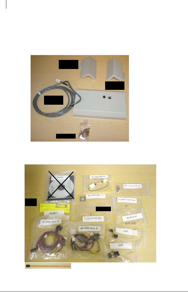
FlexLock Assembly #14-7043: Some FlexLock parts come pre-assembled for shipping purposes. They need to be separated to do the installation.
Curved Door
Bracket
Square Door
Bracket
FlexLock Unit
with cable
Cam Lock Keys
Figure 2-1. FlexLock Kit #14-7043
Installation Kit #20-6023: Includes the TempCheck temperature probe
|
|
Blue Screen |
|
|
Instruction |
|
|
||
|
|
Standoffs |
||
|
Power |
|
||
CD |
|
|
|
#94-6218 |
|
|
|
|
Bracket Cutout |
|
|
Alignmen |
|
|
#94-6233 |
|
|
t Fixture
#94-6138
|
|
|
|
|
|
#94-6158 |
|
|
|
|
|
|
|
||
|
|
#91-2052 |
|
|
|
||
|
|
|
|
||||
|
|
#91-2051 |
|
|
|||
AUX cables |
|||||||
|
|
|
|
|
|
||
Figure 2-2. FlexLock Installation Kit #20-6023 with TempCheck probe (#15-7105) [bottom]
FlexLock Installation and Configuration Guide/60-3002 Rev H |
© 2011 Omnicell, Inc. |
Hardware Installation 2-3
Kit/Parts Required
TempCheck Retrofit Kit #20-6037: Includes the FlexLock inner housing with the TempCheck compatible PCBA #40-3013
Figure 2-3. TempCheck Retrofit Kit #20-6037. Temperature probe shown wrapped in anti-static protection
Temperature probe shown un-wrapped from anti-static protection.
Figure 2-4. Temperature probe and attached ribbon-cable, ready for installation
© 2011 Omnicell, Inc. |
FlexLock Installation and Configuration Guide/60-3002 Rev H |

2-4 Hardware Installation
Kit/Parts Required
Helmer Parts
Under Counter Refrigerator
1 Spacer (321240-1)
2 Philip screws (230322)
11 Cubic Foot / 20-25 Cubic Foot Refrigerator
Omnicell FlexLock handle: (20-25 cu. ft. = 321132-1) (11 cu. ft. = 321132-2)
Spacer block (321133-1)
FlexLock Installation and Configuration Guide/60-3002 Rev H |
© 2011 Omnicell, Inc. |

Hardware Installation 2-5
Kit/Parts Required
Kits
Special accessories are available for facilities that install the Omnicell FlexLock on Helmer upright refrigerators, undercounter refrigerators, and undercounter freezers.
FlexLock Compatible Door Handles (Upright Models)
The door handle features a cutout and spacer which enable the FlexLock to wrap around the front and side of the door.
Available for single door upright refrigerators 11, 20, 25, and 26.5 cu ft. (326, 572, 714, 750 l)
Compatible with glass and solid doors
Factory or field installation
FlexLock Adapter Kit (Undercounter Models)
The adapter kit includes an extension bar that mounts to the door of the unit, allowing the FlexLock to be properly installed.
Adapter kits available for undercounter refrigerators and freezers (5 cu ft. / 142 l)
Compatible with glass and solid doors; powder coated and stainless steel exteriors
Factory installed or field installation kits available
Part # |
Description |
Size/Model |
Notes |
400848-2 |
Omnicell FlexLock Adapter Kit, Factory installed |
5 cubic feet (model 142 l) |
for UC Refrigerators and Freezers |
|
|
|
|
400782-2 |
Omnicell FlexLock Compatible Door Handle, Factory installed |
11 cubic feet (model 326 l) |
|
|
|
|
|
400782-1 |
Omnicell FlexLock Compatible Door Handle, Factory installed |
20 cubic feet (model 572) |
|
|
|
25 cubic feet (model 714) |
|
|
|
26.5 cubic feet (model 750 l) |
|
|
|
|
|
400848-1 |
Omnicell FlexLock Adapter Kit, Field installation |
5 cubic feet (model 142 l) |
for UC Refrigerators and Freezers) |
|
|
|
|
400875-2 |
Omnicell FlexLock Compatible Door Handle, Field installation |
11 cubic feet (model 326 l) |
|
|
|
|
|
400875-1 |
Omnicell FlexLock Compatible Door Handle, Field installation |
20 cubic feet (model 572) |
|
|
|
25 cubic feet (model 714) |
|
26.5 cubic feet (model 750 l)
© 2011 Omnicell, Inc. |
FlexLock Installation and Configuration Guide/60-3002 Rev H |

2-6 Hardware Installation
Installation Instructions
Installation Instructions
Preparation
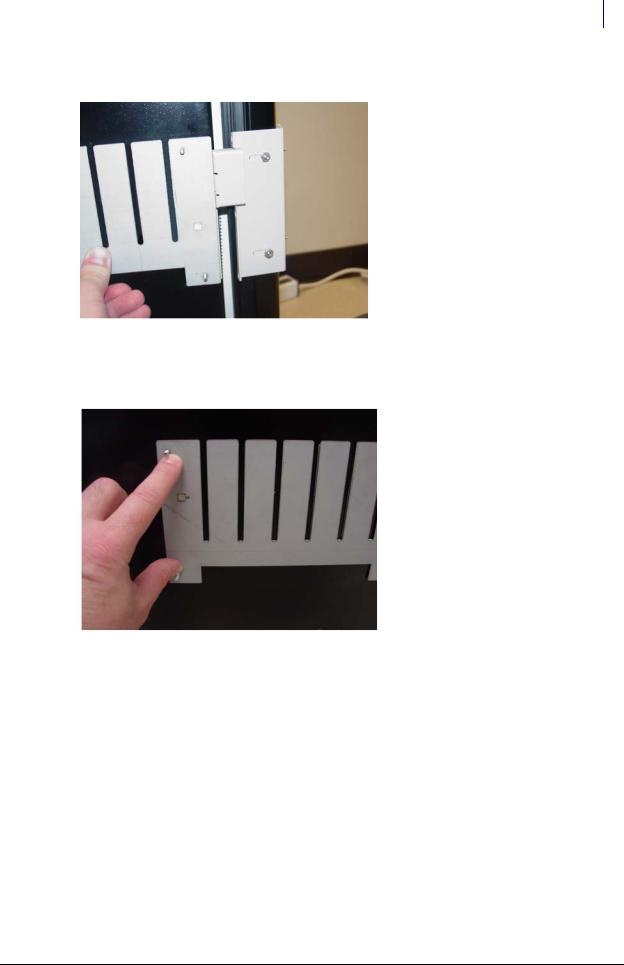
1.Use the template pattern (see “Template” on page C-1) to see if the cabinet or refrigerator is compatible with the FlexLock. There are two sides of the template—one for a square (90° angle) door, the other for a rounded door (used by such manufacturers as Sanyo or Kenmore).
a.Align the template to the door and side surface.
b.Make sure there are no gaps.
Figure 2-5. Using the template pattern
Important: Do not attempt to install the FlexLock if the refrigerator door does not fit the template pattern. See “Compatible Refrigerators” on page A-5 for space requirements and makes/models details.
2.Use an isopropyl alcohol/water mix to clean the refrigerator or cabinet surface where the FlexLock is to be placed (side where door opens—not the hinged side).
FlexLock Assembly
1.Choose a location on the refrigerator or cabinet—allowing room for the Flexlock and accessing the refrigerator/cabinet handle.
 Note: If installing the TempCheck probe, make sure the cross bar of the mounting bracket is not in line with a shelf inside the refrigerator. The TempCheck flex circuit should be able run along the inside wall of the refrigerator.
2. Select the correct door adapter for the door type.
FlexLock Installation and Configuration Guide/60-3002 Rev H |
© 2011 Omnicell, Inc. |
Hardware Installation 2-7
Installation Instructions
Door Bracket Assembly
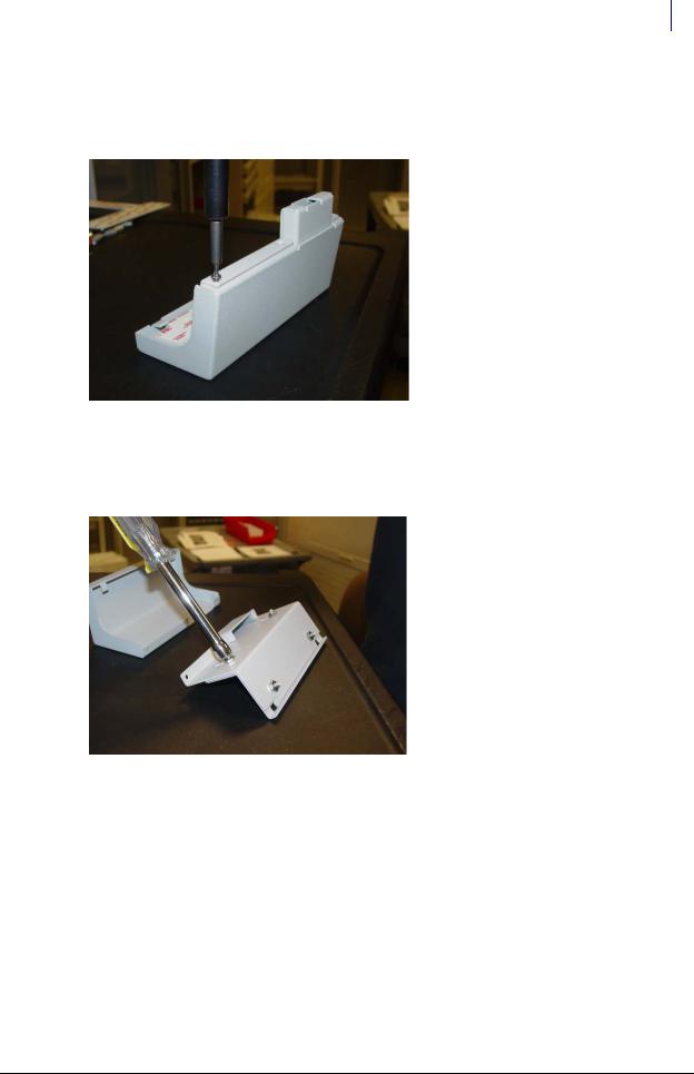
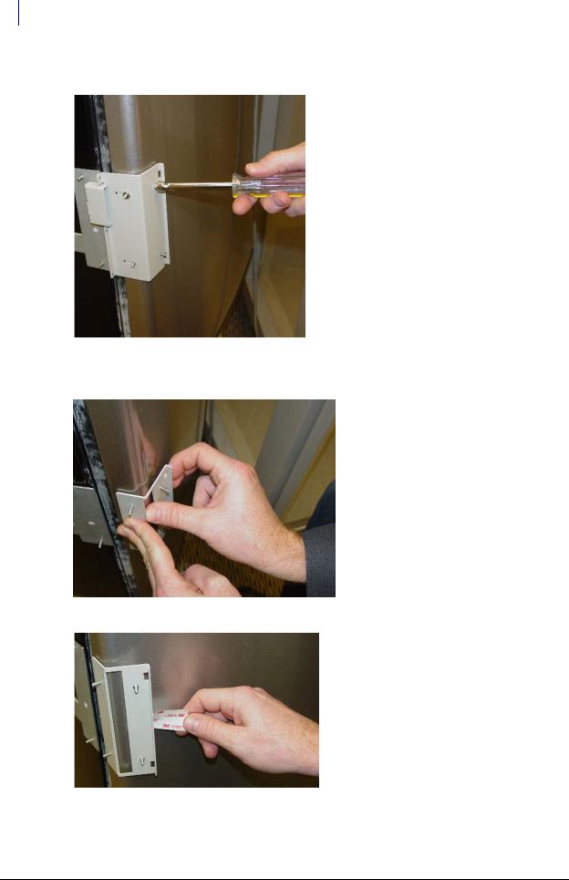
1.Remove the three T-8 screws which hold the cover plate to the door plate using a T-8 Torx Driver and retain them for later use.
Figure 2-6. Removing the cover plate
2.Remove the cover plate.
3.Remove the four 5/16 nuts which hold the door plate to the plate adapter using a 5/16 nut driver.
Figure 2-7. Removing the door plate from the plate adapter
4. Remove the door plate.
© 2011 Omnicell, Inc. |
FlexLock Installation and Configuration Guide/60-3002 Rev H |
2-8 Hardware Installation
Installation Instructions
Test Fit
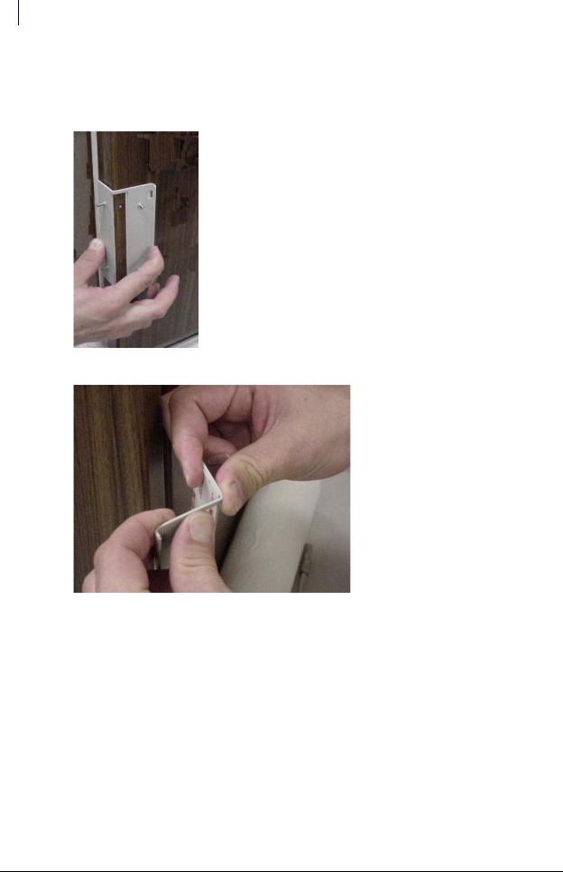
1.Test fit the door adapter against the door corner. Bend the adapter slightly to match the angle of the refrigerator if needed. A close fit is required for strength.
Figure 2-8. Testing the door adapter fit
Figure 2-9. Bending the door adapter
FlexLock Installation and Configuration Guide/60-3002 Rev H |
© 2011 Omnicell, Inc. |
Hardware Installation 2-9
Installation Instructions
2. Attach the door adapter to the correct door plate using four 5/16” Hex nuts. Hand tighten.
Figure 2-10. Assembling the door brackets
3. Test fit the door bracket assembly against the door corner.
Figure 2-11. Testing the door bracket assembly fit
Helmer Fridge Adjustment
If attaching the FlexLock to a Helmer refrigerator, extra steps and parts are needed. This setup can take up to 15 minutes. Secure the contents of the refrigerator (if any) in a secure, temperature controlled container/area during the procedure.
For the 11 cubic feet refrigerator, do the following steps:
1.Remove the existing handle from the door by removing the five mounting screws.
2.Secure the Omnicell Flexlock handle to the door using four of the original screws (two on top and two at the bottom).
3.Secure the spacer block to the door using the middle screw. Make sure that one edge lines up with the front face of door.
For the under counter refrigerator, do the following steps:
1. Remove two of the bottom door screws.
© 2011 Omnicell, Inc. |
FlexLock Installation and Configuration Guide/60-3002 Rev H |
2-10 Hardware Installation
Installation Instructions
2.Install the spacer by rotating it into position with the two screw holes aligning with the mounting holes.
3.Make sure the spacer is flush with the front of the door. If the spacer is not flush, rotate the spacer into position with the other two mounting holes to obtain the flush position.
4.Secure the spacer with two Phillips flat head screws provided with the kit.
Mounting Bracket
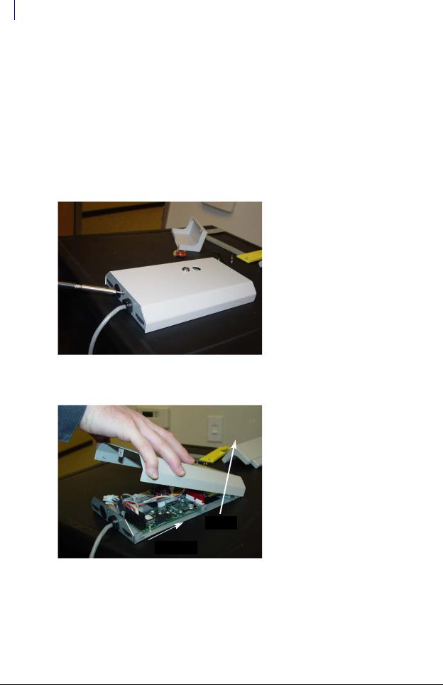
1.Use #2232 cam lock key to move the keyhole cover plate to the open (unlocked) position.
2.Remove the T-10 screw in back with a T-10 Torx driver.
3.Put on an ESD wrist strap and properly ground it.
Figure 2-12. Removing the back screw
4. Slide the outer housing back, then lift off.
2 - Lift up
1 - Slide back
Figure 2-13. Removing the outer housing
FlexLock Installation and Configuration Guide/60-3002 Rev H |
© 2011 Omnicell, Inc. |
Hardware Installation 2-11
Installation Instructions
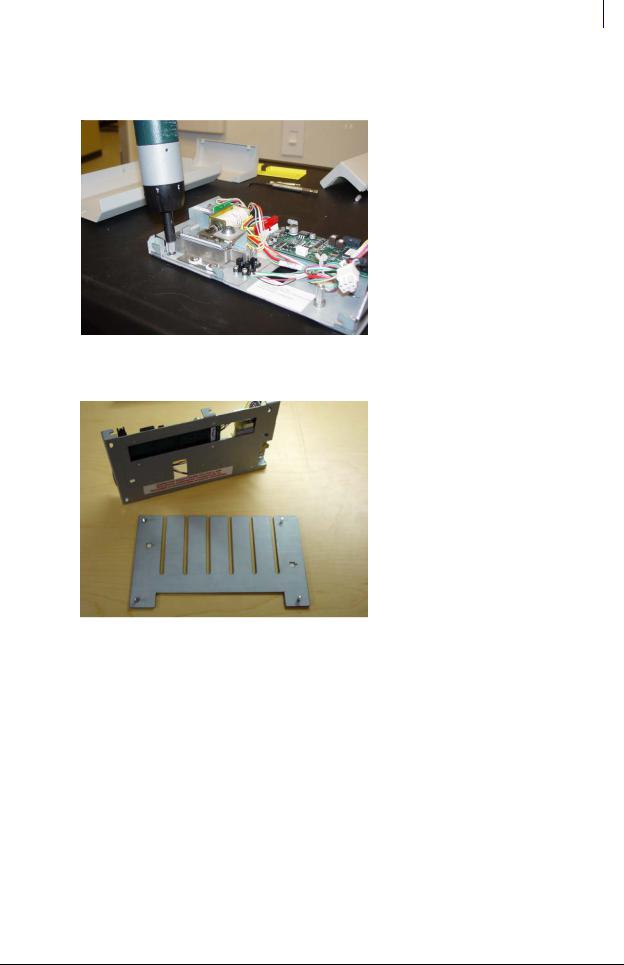
5.Remove the four 5/16” hex standoffs in each of the inner housing corners and retain them for later use.
Figure 2-14. Removing the standoffs
6. Lift the inner housing off.
Figure 2-15. Removing the inner housing
© 2011 Omnicell, Inc. |
FlexLock Installation and Configuration Guide/60-3002 Rev H |
2-12 Hardware Installation
Installation Instructions
Alignment Fixture
1.Place the mounting bracket so that the crossbar is toward the bottom and the threaded studs are facing up.
Figure 2-16. Arranging the bracket assembly
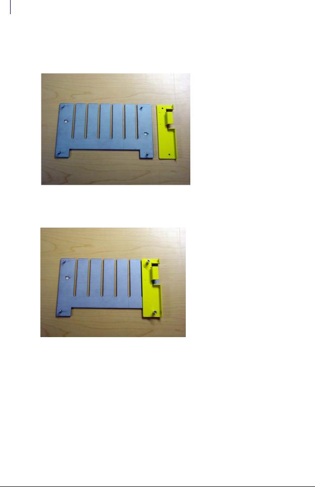
2.Lay the alignment fixture over the right side of the mounting bracket. Align the fixture’s offset stud holes with the bracket studs. The fixture’s cutout should be facing right.
Figure 2-17. Placing the alignment fixture on the mounting bracket
FlexLock Installation and Configuration Guide/60-3002 Rev H |
© 2011 Omnicell, Inc. |
Hardware Installation 2-13
Installation Instructions
3.Use two of the standoffs (removed from the inner housing) to keep the fixture in place. Do not tighten.
4.Slide in the door bracket assembly’s lock tab into the alignment fixture cutout.
5.Tighten the standoffs.
Figure 2-18. Completed bracket assembly with alignment fixture
Bracket Assembly
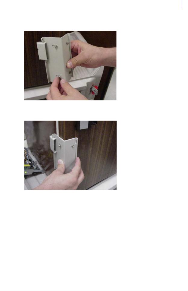
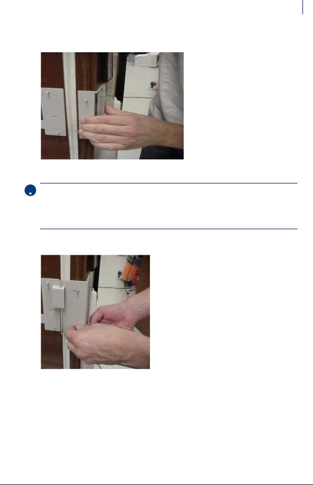
1. Fit the complete bracket assembly on the cabinet/refrigerator.
Figure 2-19. Fitting the whole bracket assembly
© 2011 Omnicell, Inc. |
FlexLock Installation and Configuration Guide/60-3002 Rev H |
2-14 Hardware Installation
Installation Instructions
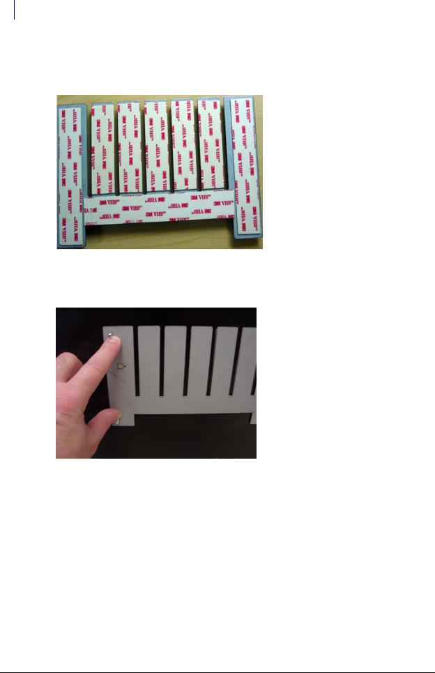
2.Turn the brackets over and remove the protective film from the adhesive strips for the mounting bracket and the side of the inner door bracket. Leave the film cover on the strip that will go on the front of the door.
Figure 2-20. Removing adhesive strip covers
3.Fit the door bracket assembly to the cabinet/refrigerator and press firmly on the mounting bracket and the side of the door bracket assembly.
Figure 2-21. Bonding the bracket assembly
FlexLock Installation and Configuration Guide/60-3002 Rev H |
© 2011 Omnicell, Inc. |
Hardware Installation 2-15
Installation Instructions
4. Remove the alignment fixture.
Figure 2-22. Bracket assembly without the alignment fixture
5.Open the refrigerator/cabinet door.
6.Press firmly on the mounting bracket to assure the adhesive has full contact.
Figure 2-23. Pressing the mounting bracket
7. Close the refrigerator/cabinet door.
© 2011 Omnicell, Inc. |
FlexLock Installation and Configuration Guide/60-3002 Rev H |
2-16 Hardware Installation
Installation Instructions
8. Remove the four 5/16” hex nuts to remove the door plate.
Figure 2-24. Removing the door plate
9. Bend the door adapter back slightly to peel off the adhesive strip cover.
Figure 2-25. Bending the door adapter
Figure 2-26. Stripping the adhesive cover
FlexLock Installation and Configuration Guide/60-3002 Rev H © 2011 Omnicell, Inc.
Hardware Installation 2-17
Installation Instructions
10. Press the door adapter firmly in place, to assure full contact from the adhesive.
Figure 2-27. Bonding the door adapter
 Important: Wait until the bond is set before proceeding to the next step. At room temperature, it will take 20 minutes for 50% bond strength; 24 hours for 90% bond strength; 72 hours for 100% bond strength. The process can be sped up by increasing the temperature 150° F for an hour.
If applicable, the TempCheck probe can be installed while waiting for the bonding process. Refer to“TempCheck Installation” on page 2-19.
11. Re-attach the door plate to the door adapter and tighten the four 5/16” nuts.
Figure 2-28. Re-attaching the door plate
12. Open the door of the refrigerator/cabinet.
© 2011 Omnicell, Inc. |
FlexLock Installation and Configuration Guide/60-3002 Rev H |
2-18 Hardware Installation
Installation Instructions
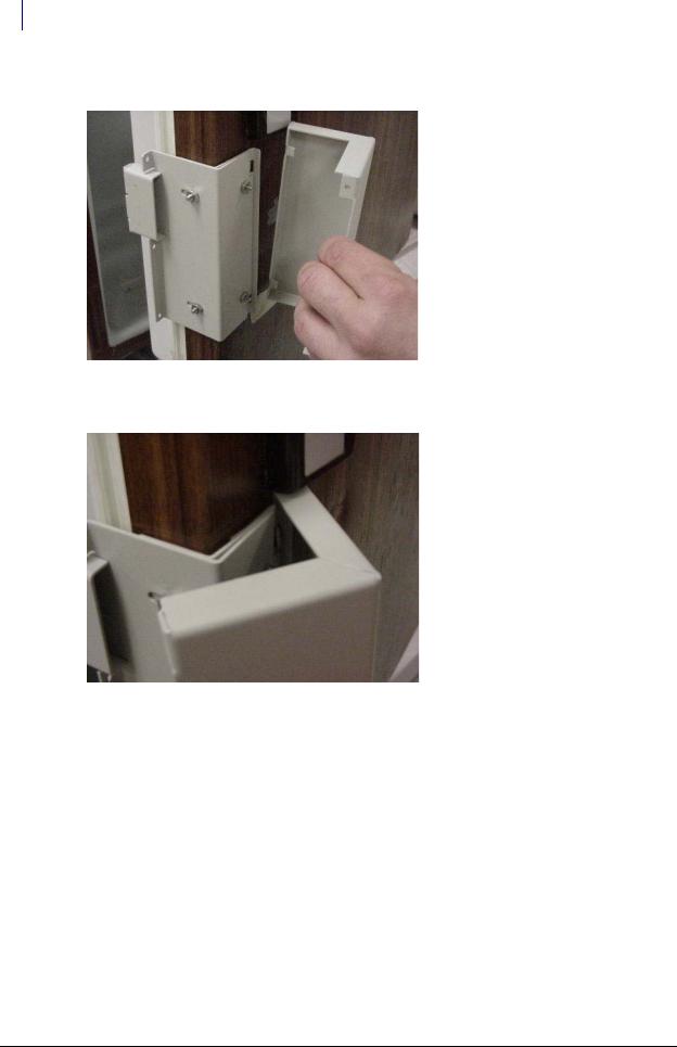
13. Match the notches on the cover plate to the door plate openings.
Figure 2-29. Matching notches
14. Move the cover plate forward until it fits without gaps.
Figure 2-30. Placing the cover plate
FlexLock Installation and Configuration Guide/60-3002 Rev H |
© 2011 Omnicell, Inc. |
Hardware Installation 2-19
Installation Instructions
15.Secure the cover plate to the door plate with the three retained T-8 Torx screws to the side of the front cover.
Figure 2-31. Securing the cover plate
TempCheck Installation
This section provides instructions for the optional installation of a TempCheck temperature probe with a new FlexLock. If performing a TempCheck retrofit for an existing FlexLock, refer to “Retrofit TempCheck” on page 2-81. If not using this optional feature, skip to the next section— “Inner Housing and Cover” on page 2-21.
Note: Most refrigerators have doors that open from the left (door hinges on the right side). If the door opens from the right side, some installation parts must be inverted.
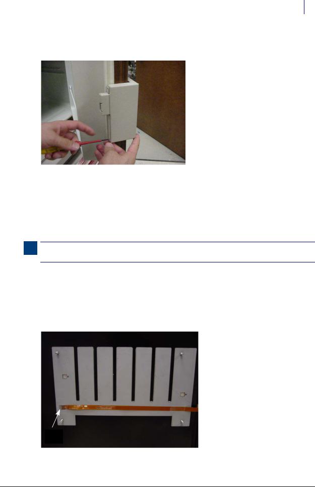
1.Clean the intended path of the TempCheck probe flex circuit inside the refrigerator with a isopropyl alcohol/water mix. The path should be level with the mounting bracket’s crossbar and not in line with a refrigerator shelf. The probe is placed on the side closest to the opening—opposite the hinges.
2.Align the contacts end of the flex circuit to the edge of the FlexLock mounting bracket and temporarily attach it with adhesive tape. Avoid taping over the circuit contacts at the end.
Circuit
Contacts
Figure 2-32. Aligning the end of the Flex Circuit with bracket.
© 2011 Omnicell, Inc. |
FlexLock Installation and Configuration Guide/60-3002 Rev H |
2-20 Hardware Installation
Installation Instructions
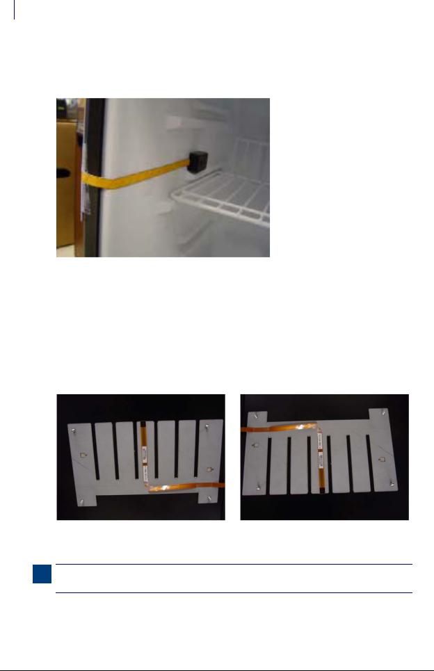
3.Pull the flex circuit tight inside the refrigerator door.
4.Install the temperature sensor end inside the refrigerator. Remove the self-adhesive cover and pull the flex circuit tight while sticking it in place.
Figure 2-33. Installing the sensor inside the refrigerator.
5.Remove the tape from the contacts end of the flex circuit.
6.Peel off the self-adhesive cover from the flex circuit.
7.Pull the flex circuit tight while carefully adhering it from inside the refrigerator to the mid point of the mounting bracket.
8.Bend the exposed end of the flex circuit at a ninety degree angle. Bend up for refrigerators that open from the left...or down for refrigerators that open from the right. The exposed contacts should be facing the refrigerator wall in either case.
Figure 2-34. Bending the Flex Circuit end up (refrigerator opens from left)............ |
or down (refrigerator opens from right). |
Note: Be sure to complete the “Bracket Assembly” steps before going to the “Inner Housing and Cover” section.
FlexLock Installation and Configuration Guide/60-3002 Rev H |
© 2011 Omnicell, Inc. |
Hardware Installation 2-21
Installation Instructions
Inner Housing and Cover
1.Place the inner housing over the mounting bracket’s threaded studs. If applicable, thread the TempCheck flex circuit through the inner housing opening.
Figure 2-35. Placing the Inner Housing in position.
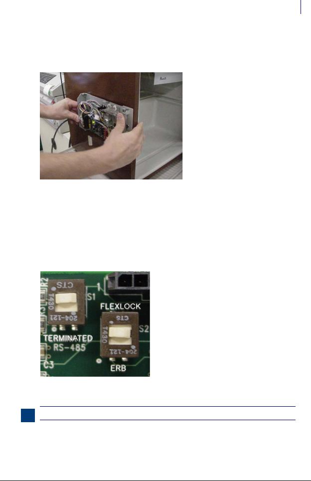
2.Place a washer on the threaded studs, then tighten the four standoffs.
3.Set the PCBA S1 slide switch to either: (see Figure 2-34)
Terminated—if the FlexLock is at the end of the AUX daisy chain or the only AUX device
Not Terminated (not marked on PCBA)—if in the middle of a daisy chain with an External Return Bin (ERB) or another FlexLock cabled to it
4.Set the PCBA S2 slide switch to FlexLock.
Figure 2-36. Checking the PCBA Switch Settings.
Note: The PCBA switch labels will be upside down when the inner housing is installed.
© 2011 Omnicell, Inc. |
FlexLock Installation and Configuration Guide/60-3002 Rev H |

2-22 Hardware Installation
Installation Instructions
5.If installing the TempCheck probe:
a.Pull out the Zero Insertion Force (ZIF) connector collar so that it is in the up (unlocked) position.
b.Loop the TempCheck probe flex circuit around without twisting to plug it into the ZIF connector. The flex circuit contacts should be facing down (if refrigerator opens from the left) or up (if refrigerator opens from the right).
c.Insert the flex circuit into the connector, then evenly press the ZIF connector collar down into the locked position.
ZIF Connector
ZIF Connector
Figure 2-37. Connecting the Flex Circuit in the Housing Assembly
6.Install the FlexLock housing cover by (1) placing it over the inner housing offset to the front, then (2) sliding it back.
2
1
Figure 2-38. Placing the Housing Cover in position.
FlexLock Installation and Configuration Guide/60-3002 Rev H |
© 2011 Omnicell, Inc. |
Loading...