

Page 1

Color Touch PC Box/Electronics Tray Upgrade
and Service Guide: PowerCom3
Overview of electronics changes and PowerCom2 to PowerCom3 swap instructions
© 2007 Omnicell, Inc. Color Touch PC Box/Electronics Tray Upgrade and Service Guide: PowerCom3/67-2015 Rev A
Page 2

This guide is CONFIDENTIAL and designed only for Omnicell Technical personnel and/or designated
representatives.
This guide and accompanying software and/or hardware described in it are protected under copyright laws and may
not be copied, wholly or in part, without the express written consent of Omnicell, Inc. The same proprietary and
copyright notices must be attached to any permitted copies as were attached to the original works.
Omnicell, Inc.
1201 Charleston Drive
Mountain View, CA 94043
(650) 251-6100
www.omnicell.com
OMNICELL, ANESTHESIA TT, DECISIONCENTER, FLEXBIN, MEDGUARD, OMNIBUYER, OMNICENTER,
OMNIEVOLVE, OMNIFLOORSTOCK, OMNIGATE, OMNILINKRX, OMNIRX, OMNISCANNER,
OMNISUPPLIER, OMNITRACK, OPEN TOUCH, OPTIFLEX, OPTIFLEX MOBILETRACK, POINT-TO-POINT
MEDICATION SAFETY, SAFETYMED, SAFETYPAK, SAFETYSTOCK, SECUREVAULT, SEE & TOUCH, SUREMED, TOUCH & GO, VCOMMANDER, VDIRECTOR, VMANAGER, VSUITE, WORKFLOWRX, and the
OMNICELL design mark are trademarks or registered trademarks of Omnicell, Inc. in the United States and
internationally.
©1999 - 2007 All rights reserved.
Color Touch PC Box/Electronics Tray Upgrade and Service Guide: PowerCom3/67-2015 Rev A © 2007 Omnicell, Inc.
Page 3

Table of Contents
Color Touch PC Box/Electronics Tray Upgrade and Service Guide: PowerCom3 . . . . . . 1-1
Overview . . . . . . . . . . . . . . . . . . . . . . . . . . . . . . . . . . . . . . . . . . . . . . . . . . . . . . . . . . . . . . . . . . . . 1-1
Features and Benefits . . . . . . . . . . . . . . . . . . . . . . . . . . . . . . . . . . . . . . . . . . . . . . . . . . . . . . 1-1
Pre-Implementation . . . . . . . . . . . . . . . . . . . . . . . . . . . . . . . . . . . . . . . . . . . . . . . . . . . . . . . 1-3
Tools List . . . . . . . . . . . . . . . . . . . . . . . . . . . . . . . . . . . . . . . . . . . . . . . . . . . . . . . . . . . . . . . . 1-4
Check the dip switches . . . . . . . . . . . . . . . . . . . . . . . . . . . . . . . . . . . . . . . . . . . . . . . . . . . . . 1-4
CTPC Box Installation . . . . . . . . . . . . . . . . . . . . . . . . . . . . . . . . . . . . . . . . . . . . . . . . . . . . . . . . 1-5
Remove the PowerCom2 CT PC Box. . . . . . . . . . . . . . . . . . . . . . . . . . . . . . . . . . . . . . . . . 1-5
Prepare the New CT PC Box for Installation . . . . . . . . . . . . . . . . . . . . . . . . . . . . . . . . . . 1-7
Install the CT PC Box . . . . . . . . . . . . . . . . . . . . . . . . . . . . . . . . . . . . . . . . . . . . . . . . . . . . . . 1-7
Field Installation of a New CT PC Tray . . . . . . . . . . . . . . . . . . . . . . . . . . . . . . . . . . . . . . . . . 1-7
Remove the PowerCom2 CT PC Tray . . . . . . . . . . . . . . . . . . . . . . . . . . . . . . . . . . . . . . . . 1-7
Remove the PowerCom2 tray from the Anesthesia Workstation . . . . . . . . . . . . 1-10
Remove the PowerCom2 tray from the Omni Rx/TT . . . . . . . . . . . . . . . . . . . . . . 1-10
Remove the PowerCom2 tray from the Omni Rx/TT . . . . . . . . . . . . . . . . . . . . . . 1-10
Install the PowerCom3 CT PC Tray. . . . . . . . . . . . . . . . . . . . . . . . . . . . . . . . . . . . . . . . . 1-11
Installing the tray into the Anethesia Workstation . . . . . . . . . . . . . . . . . . . . . . . . 1-11
Installing the tray into the Omni Rx/TT . . . . . . . . . . . . . . . . . . . . . . . . . . . . . . . . . 1-11
Installing the tray into the Half Cell . . . . . . . . . . . . . . . . . . . . . . . . . . . . . . . . . . . . . 1-11
Replace the cables . . . . . . . . . . . . . . . . . . . . . . . . . . . . . . . . . . . . . . . . . . . . . . . . . . . . 1-12
iii
We want to hear from you! . . . . . . . . . . . . . . . . . . . . . . . . . . . . . . . . . . . . . . . . . . . . Feedback-1
© 2007 Omnicell, Inc. Color Touch PC Box/Electronics Tray Upgrade and Service Guide: PowerCom3/67-2015 Rev A
Page 4

iv Table of Contents
Color Touch PC Box/Electronics Tray Upgrade and Service Guide: PowerCom3/67-2015 Rev A © 2007 Omnicell, Inc.
Page 5

Overview
Color Touch PC Box/Electronics Tray Upgrade and Service Guide: PowerCom3 1-1
Overview
Color Touch PC Box/Electronics
Tray Upgrade and Service Guide:
PowerCom3
This chapter identifies and describes the new hardware on the Color Touch PC Box (referred to
in this manual as the CT PC Box) and electronics tray.
The new CT PC Box has been redesigned to:
Increase efficiency
Decrese assembly costs
Minimize internal differences with the electronics Tray setups.
Features and Benefits
The new setup has:
A PowerCom3 board
A single 300W AC/DC Power Supply
A 20-minute battery backup
Metal friction Printed Circuit Board Assembly (PCBA) standoffs
A new Universal Serial Bus (USB) diagnostics port for laptop interface
Dual cooling fans
A 2500A Transient Voltage Suppressor (TVS) for surge protection
An added AUX termination switch for easier power on and off operation.
In addition, the CT PC Box hard disc drive (HDD) has been relocated and given added shock
absorbing mounts. The power supply and battery are mounted on the same bracket to save space.
A failure detection alarm has been installed to indicate fan failure and a battery status indicator
buzzer has been added to alert the user when the battery backup is getting low.
© 2007 Omnicell, Inc. Color Touch PC Box/Electronics Tray Upgrade and Service Guide: PowerCom3/67-2015 Rev A
Page 6
1-2 Color Touch PC Box/Electronics Tray Upgrade and Service Guide: PowerCom3
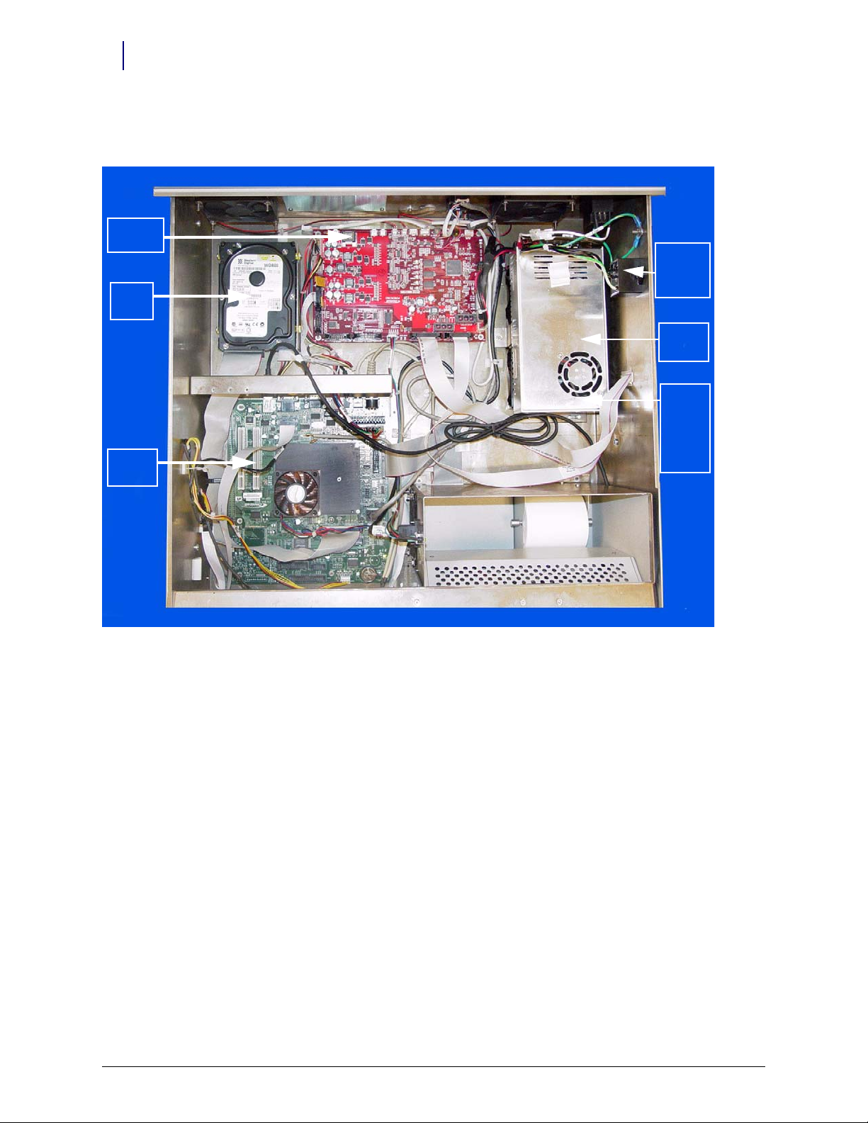
Hard
Drive
Mother
Board
Tra ns ie nt
Volt age
Suppressor
Power
Supply
Power Com3
Board
Backup
Battery
(Located
below
Power
Supply)
Overview
The DC/DC Power Supply has been integrated into the PowerCom3 board, increasing efficiency
and available space in the CT PC Box and tray.
Figure 1-1. Location of components within CT PC Box with PowerCom3 board
Color Touch PC Box/Electronics Tray Upgrade and Service Guide: PowerCom3/67-2015 Rev A © 2007 Omnicell, Inc.
Page 7
Color Touch PC Box/Electronics Tray Upgrade and Service Guide: PowerCom3 1-3
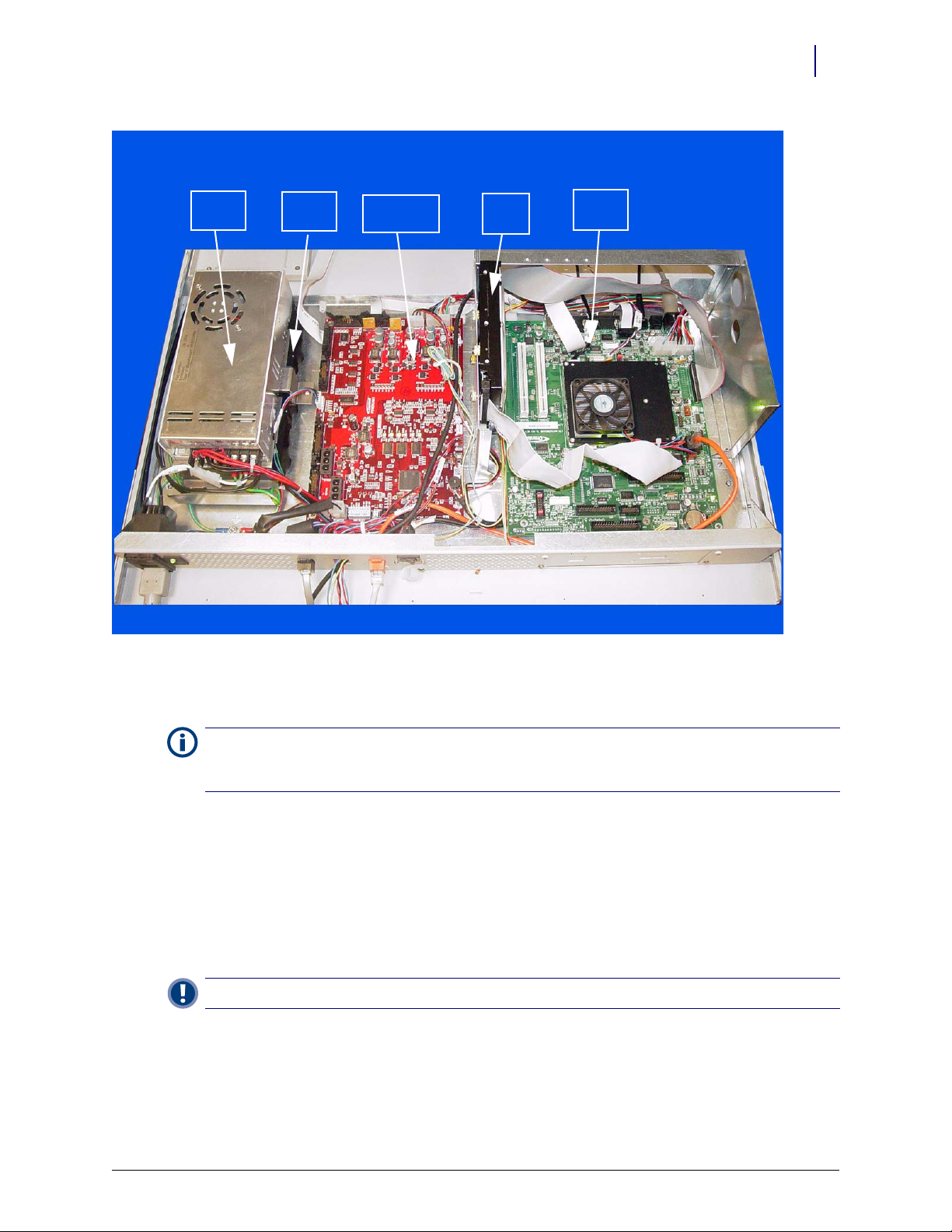
Power Com3
Board
Hard
Drive
Mother
Board
Power
Supply
Backup
Battery
Overview
Figure 1-2. CT PC Tray with PowerCom3 Board
Pre-Implementation
Note: To clear up any possible confusion in the following procedure, the CT PC Box with a PowerCom2 board
will be called the PowerCom2 CT PC Box. The CT PC Box with the new PowerCom3 board will be called the
PowerCom3 CT PC Box.
It is not possible to upgrade from a PowerCom2 CT PC Box to a PowerCom3 CT PC Box. The
entire unit must be swapped out. Before performing the swap in the field, be sure to review the
following documents and procedures:
Important: A Pharmacist must be present when servicing drawers where medications are present.
Refer to the Removing and Replacing Pharmacy II Drawers chapter in the OmniSupplier Manual
CD.
OmniSupplier Color Touch chapter in the Technical Manual for Color Touch Software
Version JT5.3x.
Omnicell Drug Handling Policy and Procedures for information regarding the removal of
drugs from the Pharmacy drawers.
© 2007 Omnicell, Inc. Color Touch PC Box/Electronics Tray Upgrade and Service Guide: PowerCom3/67-2015 Rev A
Page 8

1-4 Color Touch PC Box/Electronics Tray Upgrade and Service Guide: PowerCom3
Overview
Tools List
The following tools are needed to install the CT PC Box:
9/64” Allen Wrench
T15 Torx Driver
T10 Torx Driver
T8 Torx Driver
Check the dip switches
Switch labeled as SW1 MODE SELECT on the board determines the mode of PowerCom3
operation. Generally, all switches need to be off.
Special selection can be made in the following instances:
When PowerCom3 is used in old OmniRX sled with small 18V battery with power on/off
switch on the power entry module.
When PowerCom3 is used in AUX. In this case the main communication is coming from
AUX connector instead of the PC Interface connector.
When PowerCom3 is used in burn-in room to disable the shutdown if the temperature
reaches above 115 ºF.
When PowerCom3 is used in OmniRX sled with no FAN.
When two other mode selection switches are reserved for future implementation.
Pin Name Descriptions CTPC Rx Sled Aux Old Sled
1 OLD RX Set to old RX mode with small battery OFF OFF OFF ON OFF
2 AUX Set to AUX mode OFF OFF ON ON OFF
3HIGH
TEMP
4 NO FAN Disable fan error detection OFF ON OFF OFF ON
Disable high temperature shutdown OFF OFF OFF OFF OFF
Table 1-1. PowerCom3 Dip Switches
Supply
Mobile
Cart
Color Touch PC Box/Electronics Tray Upgrade and Service Guide: PowerCom3/67-2015 Rev A © 2007 Omnicell, Inc.
Page 9

Pin Name Descriptions CTPC Rx Sled Aux Old Sled
5 MOBILE Lithium Ion Battery Select OFF OFF OFF OFF ON
6 MODE 6 Not used OFF OFF OFF OFF OFF
7 Not used OFFOFFOFFOFFOFF
8 Not used OFFOFFOFFOFFOFF
Table 1-1. PowerCom3 Dip Switches
CTPC Box Installation
Remove the PowerCom2 CT PC Box
Prior to swapping the CT PC Box, establish a process for supply/medication removal so the
nurses can track transactions while the system is down. (Example forms are located in the
Implementation Guide.)
1. Perform a graceful shutdown of the cabinet software, then power down the cabinet and
disconnect the machine from the wall outlet.
2. Disconnect the LAN cable and the AUX cables from the rear of the CT PC Box.
Color Touch PC Box/Electronics Tray Upgrade and Service Guide: PowerCom3 1-5
CTPC Box Installation
Supply
Mobile
Cart
Figure 1-3. Location and labels for LAN and AUX cable connections on CT PC Box
© 2007 Omnicell, Inc. Color Touch PC Box/Electronics Tray Upgrade and Service Guide: PowerCom3/67-2015 Rev A
Page 10

1-6 Color Touch PC Box/Electronics Tray Upgrade and Service Guide: PowerCom3
Battery
Cable
CTPC Box Installation
3. Remove the PowerCom2 CT PC Box.
a. Pull open the keyboard door to access the screws fastening the CT PC Box to the frame.
b. Remove the buttonhead 8-32 x 7/8” and buttonhead 8-32 x 3/8” screws.
c. Slowly pull the CT PC Box from the frame until the side-mounted slides lock and stop.
d. Unlock the CT PC Box cover with the cam lock key #2036.
e. Remove the cover by lifting the front end and pulling away from the cabinet.
f. Disconnect the SPC cables from the PowerCom2 board. Remove the cables from
underneath the power supply and out of the shee metal enclosure.
g. Tuck the SPC cables - still connected to the wireway - under the transport handle on the
side of the OmniSupplier frame.
h. Release the CT PC Box from the slides, carefully remove it from the cabinet and set it on a
flat surface.
Caution:
person to help lift and remove the CT PC Box from the OmniSupplier cabinet.
The CT PC Box is heavy. Trying to lift or remove the box alone could result in injury. Use a second
4. Prepare the PowerCom2 CT PC Box for return.
a. Unplug the battery from J5 on the PowerCom2 board.
National Transportation Safety Board (NTSB) regulations prohibit an uninterrupted
power supply (UPS) from being connected during transport.
Figure 1-4. Location of battery cable on motherboard of PowerCom2 CT PC Box
b. Replace and lock the top cover.
c. Once the PowerCom3 CT PC Box has been removed from the shipping box and installed
in the cabinet, place the PowerCom2 CT PC Box in the shipping box and secure it for
return.
Color Touch PC Box/Electronics Tray Upgrade and Service Guide: PowerCom3/67-2015 Rev A © 2007 Omnicell, Inc.
Page 11

Color Touch PC Box/Electronics Tray Upgrade and Service Guide: PowerCom3 1-7
Prepare the New CT PC Box for Installation
The PowerCom3 CT PC box is lighter than the PowerCom2 box and does not require two people
for installation and/or removal.
Follow ESD safety procedures. Always wear an ESD strap when working with electronic components.
Note:
1. Unlock the PowerCom3 CT PC Box top cover with the cam lock key #2036.
2. Lift the front cover and slide it forward to remove.
3. Locate the cable to the battery and instert the connector into the PowerCom3 board at J2.
Field Installation of a New CT PC Tray
Figure 1-5. Connect the Battery Cable to J2 of the PowerCom3 Board
Install the CT PC Box
1. Remove the PowerCom3 CT PC Box from the shipping box and lift it onto the rail slides of the
cabinet. Do not slide the CT PC Box completely into the cabinet.
2. Thread the SPC cable into the CT PC Box and connect it to J12 and J13 of PowerCom3 board.
3. Replace the cover and lock it using the cam lock key #2036.
4. Slide the CT PC Box completely into the cabinet.
5. Pull open the keyboard door to access the screws fastening the CT PC Box to the frame.
6. Replace the buttonhead 8-32 x 7/8” and buttonhead 8-32 x 3/8” screws.
Field Installation of a New CT PC Tray
Remove the PowerCom2 CT PC Tray
1. Perform a graceful shutdown of the cabinet software, then power down the cabinet and
disconnect the machine from the wall outlet.
© 2007 Omnicell, Inc. Color Touch PC Box/Electronics Tray Upgrade and Service Guide: PowerCom3/67-2015 Rev A
Page 12

1-8 Color Touch PC Box/Electronics Tray Upgrade and Service Guide: PowerCom3
Field Installation of a New CT PC Tray
2. Disconnect the LAN cable and the AUX cables from the rear of the CT PC Box.
Figure 1-6. Location and labels for LAN and AUX cable connections on CT PC Tray
3. Access the electronics tray.
Color Touch PC Box/Electronics Tray Upgrade and Service Guide: PowerCom3/67-2015 Rev A © 2007 Omnicell, Inc.
Page 13

Color Touch PC Box/Electronics Tray Upgrade and Service Guide: PowerCom3 1-9
4. Disconnect the following cables (from tray only):
a. LCD data cable
b. Contrast cable
c. Inverter (backlight) cable
d. Touch screen data cable
e. Keyboard cable
f. Speaker cable
g. Card reader cable (if applicable–not shown)
h. Fan power cable (if applicable)
i. Printer cable (free cable from any clips)
j. Cabinet power/comm cable
Field Installation of a New CT PC Tray
Figure 1-7. Location of cables on the CT PC Tray with PowerCom2 Board
© 2007 Omnicell, Inc. Color Touch PC Box/Electronics Tray Upgrade and Service Guide: PowerCom3/67-2015 Rev A
Page 14

1-10 Color Touch PC Box/Electronics Tray Upgrade and Service Guide: PowerCom3
Field Installation of a New CT PC Tray
Remove the PowerCom2 tray from the Anesthesia Workstation
1. Turn the two 1/4-turn fastners securing the electronics tray counter-clockwise to unlock.
Figure 1-8. Lift and remove the CT PC Tray with from the Anesthesia Workstation
2. Lift the front edge of the tray over the two standoffs and pull the tray forward.
3. Lift the rear of the tray and twist slightly until the front tabs clear the frame.
4. Remove the electronics tray.
Remove the PowerCom2 tray from the Omni Rx/TT
1. Turn the two 1/4-turn fastners securing the electronics tray counter-clockwise to unlock.
2. Lift and remove the electronics tray.
Remove the PowerCom2 tray from the Omni Rx/TT
1. Lift and remove the electronics tray.
Color Touch PC Box/Electronics Tray Upgrade and Service Guide: PowerCom3/67-2015 Rev A © 2007 Omnicell, Inc.
Page 15

Install the PowerCom3 CT PC Tray
Installing the tray into the Anethesia Workstation
1. Place the new electronics tray into the cabinet. Place the rear of the tray in first and lower until
it touches the back of the tray.
Color Touch PC Box/Electronics Tray Upgrade and Service Guide: PowerCom3 1-11
Field Installation of a New CT PC Tray
Figure 1-9. Place the CT PC Tray into the Anesthesia Workstation
a. Ensure the front of the tray clears the frame of the tray and set the tray down.
b. Secure the tray onto the standoffs.
c. Turn the two 1/4-turn fastners securing the electronics tray clockwise to lock the tray into
place.
Installing the tray into the Omni Rx/TT
a. Place the new electronics tray into the cabinet.
b. Turn the two 1/4-turn fastners securing the electronics tray clockwise to lock the tray into
place.
Installing the tray into the Half Cell
a. Place the new electronics tray into the cabinet.
© 2007 Omnicell, Inc. Color Touch PC Box/Electronics Tray Upgrade and Service Guide: PowerCom3/67-2015 Rev A
Page 16

1-12 Color Touch PC Box/Electronics Tray Upgrade and Service Guide: PowerCom3
Field Installation of a New CT PC Tray
Replace the cables
1. Connect the wireway cable to the J10 of the PowerCom3 Board
.
Figure 1-10. Connect the Wireway Cable to J10 of the PowerCom3 Board
2. Connect the printer cable to J27 on the motherboard.
Figure 1-11. Connect the Printer Cable to J27 of the Motherboard
Note:
Ensure that the red wire is connected closest to Pin 1.
3. Connect the fan power cable to J17 on the UPS board (if applicable).
Color Touch PC Box/Electronics Tray Upgrade and Service Guide: PowerCom3/67-2015 Rev A © 2007 Omnicell, Inc.
Page 17

Color Touch PC Box/Electronics Tray Upgrade and Service Guide: PowerCom3 1-13
4. Connect the speaker cable to port J45 on the motherboard.
Field Installation of a New CT PC Tray
Figure 1-12. Connect the Speaker Cable to J45 of the Motherboard
5. Connect the keyboard cable to port J42 on the motherboard.
Figure 1-13. Connect the Keyboard Cable to J42 of the Motherboard
© 2007 Omnicell, Inc. Color Touch PC Box/Electronics Tray Upgrade and Service Guide: PowerCom3/67-2015 Rev A
Page 18

1-14 Color Touch PC Box/Electronics Tray Upgrade and Service Guide: PowerCom3
Field Installation of a New CT PC Tray
6. Connect the touch screen data cable to J2 on the motherboard:
a. Connect the extension cable provided in the kit to the touch screen data cable (red wire to
red wire).
b. Wrap the joined connectors with electrical tape to ensure that the cables do not become
disconnected.
c. Connect the touch screen data cable extension to J2 on the motherboard.
Figure 1-14. Connect the Touch Screen Data Cable to J2 of the Motherboard
7. Connect the inverter cable (backlight) to J32 on the motherboard.
Figure 1-15. Connect the Backlight Cable to J32 of the Motherboard
Color Touch PC Box/Electronics Tray Upgrade and Service Guide: PowerCom3/67-2015 Rev A © 2007 Omnicell, Inc.
Page 19

Color Touch PC Box/Electronics Tray Upgrade and Service Guide: PowerCom3 1-15
8. Connect the contrast cable to J31 on the motherboard.
Field Installation of a New CT PC Tray
Figure 1-16. Connect the Contrast Cable to J31 of the Motherboard
9. Connect the LCD data cable to J37 on the motherboard
Figure 1-17. Connect the LCD Data Cable to J37 of the Motherboard
10. If a card reader is present and needs to be reconnected:
a. Connect the card reader serial cable to J47 on the motherboard.
b. Connect the card reader power cable to the back of the card reader serial connector.
c. Insert card reader power cable pins into the disk drive power connector.
d. Align the red-stripe pin to the red cable and the gray-stripe pin to the gray cable in next
spot.
© 2007 Omnicell, Inc. Color Touch PC Box/Electronics Tray Upgrade and Service Guide: PowerCom3/67-2015 Rev A
Page 20

1-16 Color Touch PC Box/Electronics Tray Upgrade and Service Guide: PowerCom3
Field Installation of a New CT PC Tray
Color Touch PC Box/Electronics Tray Upgrade and Service Guide: PowerCom3/67-2015 Rev A © 2007 Omnicell, Inc.
Page 21

We want to hear from you!
This document is designed to provide relevant technical information to those responsible for the
implementation, service, and support of Omnicell products. The Documentation team needs
your input, so we can continue to improve our publications.
Please send us your feedback:
Did this document meet your needs? If so, please let us know what we’re doing right. If not, please
provide specific feedback. Email or fax your feedback as follows:
Email: Documentation Requests email group at documentationrequests@omnicell.com (specify the
document title or PN).
Fax: send this page, along with your feedback, to (650) 251-6266, attention: Documentation.
Name: Email:
Dept./Title: Phone:
Feed back:
© 2007 Omnicell, Inc. Color Touch PC Box/Electronics Tray Upgrade and Service Guide: PowerCom3/67-2015 Rev A
Page 22

 Loading...