

Page 1

OmniTrack Installation
Guide
67-2055 Rev A
Page 2

This guide is CONFIDENTIAL and designed only for Omnicell Technical personnel and/or designated
representatives.
This guide and accompanying software and/or hardware described in it are protected under copyright laws and may
not be copied, wholly or in part, without the express written consent of Omnicell, Inc. The same proprietary and
copyright notices must be attached to any permitted copies as were attached to the original documents.
Omnicell, Inc.
1201 Charleston Road
Mountain View, CA 94043
(650) 251-6100
www.omnicell.com
OMNICELL and the OMNICELL design mark, DECISIONCENTER, OMNIBUYER, OMNICENTER, OMNIRX,
OMNISUPPLIER, and SURE-MED, are registered trademarks. ANESTHESIA TT, FLEXBIN, MEDGUARD,
OMNIEVOLVE, OMNIFLOORSTOCK, OMNIGATE, OMNILINKRX, OMNISCANNER, OMNITRACK,
OPEN TOUCH, OPTIFLEX, OPTIFLEX MOBILETRACK, POINT-TO-POINT MEDICATION SAFETY,
PROSERV 1, SAFETYMED, SAFETYPAK, SAFETYSTOCK, SECUREVAULT, SEE & TOUCH, SINGLEPOINTE,
TEMPCHECK, TOUCH & GO, VCOMMANDER, VDIRECTOR, VMANAGER, VSUITE, and WORKFLOWRX are
trademarks of Omnicell, Inc. in the United States and internationally. All other trademarks and trade names are the
property of their respective owners.
Copyright 2009 Omnicell, Inc. All rights reserved.
OmniTrack Installation Guide/67-2055 Rev A © 2009 Omnicell, Inc.
Page 3

Table of Contents
OmniTrack Installation and Programming Instructions . . . . . . . . . . . . . . . . . . . . . . . . . . 1-1
Overview . . . . . . . . . . . . . . . . . . . . . . . . . . . . . . . . . . . . . . . . . . . . . . . . . . . . . . . . . . . . . . . . . . . . 1-1
Tools . . . . . . . . . . . . . . . . . . . . . . . . . . . . . . . . . . . . . . . . . . . . . . . . . . . . . . . . . . . . . . . . . . . . 1-1
Installing the OmniTrack . . . . . . . . . . . . . . . . . . . . . . . . . . . . . . . . . . . . . . . . . . . . . . . . . . . . . 1-1
Reassembling the OmniTrack. . . . . . . . . . . . . . . . . . . . . . . . . . . . . . . . . . . . . . . . . . . . . . . . . . 1-3
Programming the OmniTrack . . . . . . . . . . . . . . . . . . . . . . . . . . . . . . . . . . . . . . . . . . . . . . . . . 1-5
Set Programming Mode . . . . . . . . . . . . . . . . . . . . . . . . . . . . . . . . . . . . . . . . . . . . . . . . . . . . 1-5
Zone Address . . . . . . . . . . . . . . . . . . . . . . . . . . . . . . . . . . . . . . . . . . . . . . . . . . . . . . . . . . . . . 1-6
Host Zone Address . . . . . . . . . . . . . . . . . . . . . . . . . . . . . . . . . . . . . . . . . . . . . . . . . . . . . . . . 1-7
SecureTrack Association . . . . . . . . . . . . . . . . . . . . . . . . . . . . . . . . . . . . . . . . . . . . . . . . . . . 1-7
Bin Type . . . . . . . . . . . . . . . . . . . . . . . . . . . . . . . . . . . . . . . . . . . . . . . . . . . . . . . . . . . . . . . . . 1-7
Switchpanel Bin Type . . . . . . . . . . . . . . . . . . . . . . . . . . . . . . . . . . . . . . . . . . . . . . . . . . 1-8
Supply Drawer Bin Type . . . . . . . . . . . . . . . . . . . . . . . . . . . . . . . . . . . . . . . . . . . . . . . . . . . 1-8
Exit Programming Mode . . . . . . . . . . . . . . . . . . . . . . . . . . . . . . . . . . . . . . . . . . . . . . . . . . . 1-9
Configuring the OmniSupplier Software . . . . . . . . . . . . . . . . . . . . . . . . . . . . . . . . . . . . . . . 1-9
Special Considerations: . . . . . . . . . . . . . . . . . . . . . . . . . . . . . . . . . . . . . . . . . . . . . . . . . . . . 1-9
OmniTrack with SecureTrack . . . . . . . . . . . . . . . . . . . . . . . . . . . . . . . . . . . . . . . . . . . 1-9
OmniTrack with Pharmacy Zone . . . . . . . . . . . . . . . . . . . . . . . . . . . . . . . . . . . . . . . . 1-9
Example Configuration . . . . . . . . . . . . . . . . . . . . . . . . . . . . . . . . . . . . . . . . . . . . . . . . . . . . 1-9
iii
Documentation Feedback . . . . . . . . . . . . . . . . . . . . . . . . . . . . . . . . . . . . . . . . . . . . . . . . . . . FB-1
© 2009 Omnicell, Inc. Document_Title/##-#### Rev A
Page 4

iv Table of Contents
Document_Title/##-#### Rev A © 2009 Omnicell, Inc.
Page 5
Overview
OmniTrack Installation and Programming Instructions 1-1
Overview
OmniTrack Installation and
Programming Instructions
The OmniTrack was developed to track and record the use of items that reside outside as well as
inside the Omnicell cabinet. Because the OmniTrack panel can be added to any cabinet, it is an
ideal solution when space limitations prohibit the placement of additional storage racks.
Too ls
The following tools will be required t perform the procedure:
T15 Torx screwdriver
Phillips head screwdriver
Installing the OmniTrack
1. Remove the switchpanels and the corresponding shelves and brackets that are to be replaced by
the OmniTrack.
© 2009 Omnicell, Inc. OmniTrack Installation Guide/67-2055 Rev A
Page 6

1-2 OmniTrack Installation and Programming Instructions
Installing the OmniTrack
2. Attach the left and right brackets to the frame.
Figure 1-1. OmniTrack bracket
3. Connect the OmniTrack to the wireway using the flex connector.
To install the OmniTrack directly above the PC box check the wireway for a 10 pin or a 14 pin
Note:
connector. If there is a 10 pin connector, use the standard connector. If there is only a 14 pin connector,
use the 14-pin cable that came in the OmniTrack kit.
Figure 1-2. Flex connector and the cabinet wireway
4. Insert the OmniTrack into the brackets.
OmniTrack Installation Guide/67-2055 Rev A © 2009 Omnicell, Inc.
Page 7

OmniTrack Installation and Programming Instructions 1-3
Reassembling the OmniTrack
5. Secure the OmniTrack in place, using the screws provided with the kit. Use a Phillips head
screwdriver.
Figure 1-3. Secure the OmniTrack with the screws provided.
Note: If possible, use all eight screws provided; otherwise, use at least four screws in the top or bottom,
whichever is more accessible.
Reassembling the OmniTrack
1. Insert the switchpanel into the extrusion.
Figure 1-4.
Note: The notch on the right side of the extrusion is there to accomodate the cable connectors on the
switchpanel.
© 2009 Omnicell, Inc. OmniTrack Installation Guide/67-2055 Rev A
Page 8

1-4 OmniTrack Installation and Programming Instructions
Reassembling the OmniTrack
2. Connect each of the 32 button bar cable connectors to the controller board.
Figure 1-5.
Figure 1-6.
Wires must be connected and not rearranged. Note the orientation of PCBA within the extrusion.
Note:
3. Connect the “controller to SPC” (part # 42-7015) cable to the controller, or when installing the
OmniTrack directly above the PC Box, connect the flex connector (part # 42-31230).
OmniTrack Installation Guide/67-2055 Rev A © 2009 Omnicell, Inc.
Page 9

OmniTrack Installation and Programming Instructions 1-5
Programming the OmniTrack
4. Insert the controller cover plate into the outermost groove on the extrusion.
Figure 1-7.
5. Test the brackets to ensure that they fit snugly against the extrusion.
Programming the OmniTrack
The OmniTrack functions in the same manner as standard OmniSupplier switchpanels.
Programming the OmniTrack, however, is somewhat different. Please follow the instructions
below to program your OmniTrack:
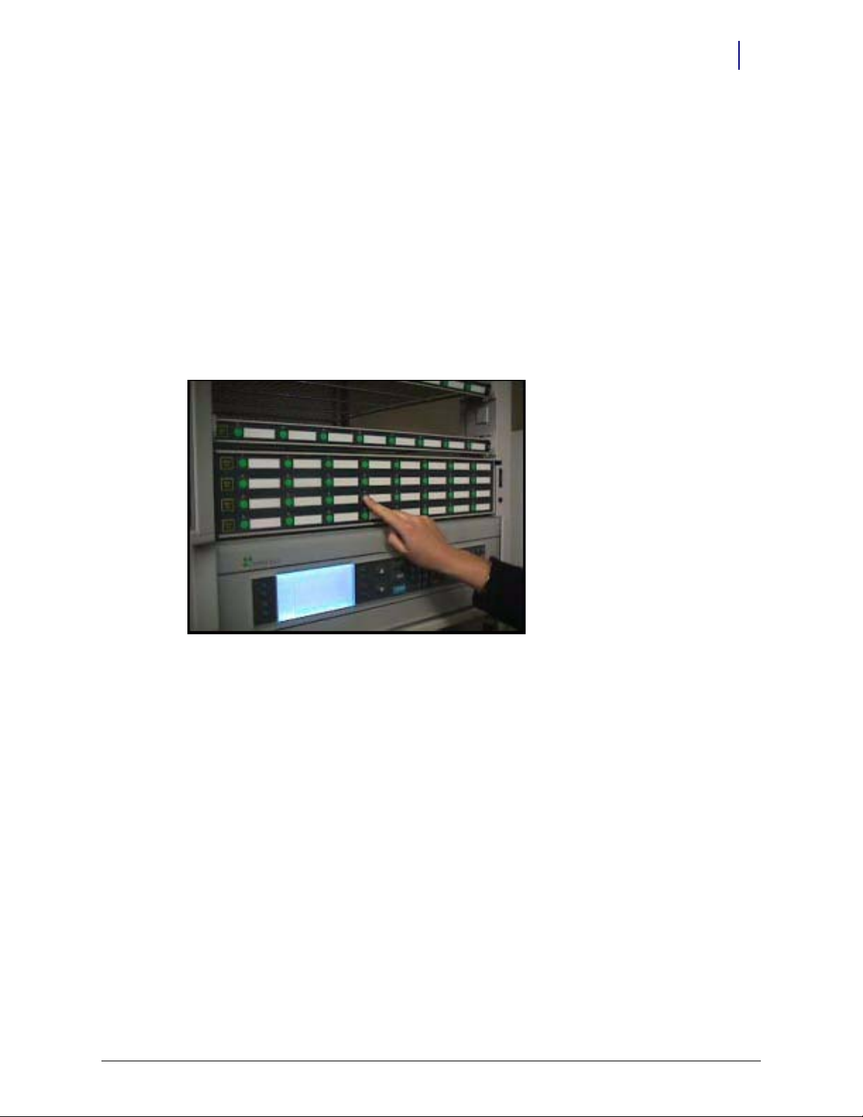
Set Programming Mode
1. Power on the cabinet.
2. Set the OmniTrack into programming mode by pressing and holding down the upper left
Return Item button for approximately ten seconds until the bottom row LEDs light up.
Figure 1-8.
In programming mode, the OmniTrack LEDs represent the following:
Row One: Zone address
© 2009 Omnicell, Inc. OmniTrack Installation Guide/67-2055 Rev A
Page 10

1-6 OmniTrack Installation and Programming Instructions
Row 1
Row 2
Row 3
Row 4
Programming the OmniTrack
Row Two: Host zone (physical location of the OmniTrack)
Row Three: Bin type (32 button switch panel or 32 button supply drawer)
Row Four: Exit buttons
Figure 1-9.
Program the OmniTrack for zone, physical location, and bin type using the following
directions:
Zone Address
Use the top row of LEDs to set the zone address. Binary numbering (starting from the far left
button; 1,2,4,8,16,32,64) is used.
The eighth button is not used.
Figure 1-10.
Several sample addresses are shown below:
Button# 1234567
Binary Value1248163264
off off off off off off off = Zone 0
ON off off off off off off = Zone 1
offONONoffoffoffoff= Zone 6 (2+4)
ON ON ON ON off off off = Zone 15 (1+2+4+8)
If the OmniTrack is being used for off-Omni items or for SecureTrack items, set the zone address
to Zone 9 or any other appropriate auxilliary/imaginary zone.
If the OmniTrack is being used for pharmacy items with a refrigerator either on or off the
OmniSupplier, set the zone address to the zone in which the OmniTrack is physically located.
OmniTrack Installation Guide/67-2055 Rev A © 2009 Omnicell, Inc.
Page 11

Host Zone Address
Use the second row of LEDs to set the host zone address. As above, binary numbering (starting
from the far left button; 1,2,4,8,16,32,64) is used.
Figure 1-11.
If the OmniTrack is being used for off-Omni items or for SecureTrack items, set the host zone
address to the zone in which it is physically located.
If the OmniTrack is being used in a pharmacy zone, this address is unimportant because the
OmniTrack needs to be set to a supply drawer address (not a host zone address). However, to
lessen confusion, it is suggested that the host zone address be set to the zone in which the
OmniTrack is physically located.
OmniTrack Installation and Programming Instructions 1-7
Programming the OmniTrack
SecureTrack Association
If the OmniTrack is being used to run a SecureTrack, turn on the first item button from the right
side of Row Two of the OmniTrack.
Figure 1-12.
Bin Type
Set the bin type using the fourth item button from the left on Row Three of the OmniTrack.
ON = Supply Drawer addressing OFF = Switchpanel addressing
Figure 1-13.
In this diagram, the OmniTrack is set up as a supply drawer in the first row of zone 0.
© 2009 Omnicell, Inc. OmniTrack Installation Guide/67-2055 Rev A
Page 12

1-8 OmniTrack Installation and Programming Instructions
Programming the OmniTrack
The OmniTrack can be addressed like a switchpanel with button numbers from 0-31 (one zone =
five switchpanels each having eight item buttons); or like a supply drawer with button numbers
from 40 - 199. These two types of addressing make it possible to use the OmniTrack in any zone
with any configuration.
Switchpanel Bin Type
Use the switchpanel bin addressing when using the OmniTrack with a SecureTrack or to keep
track of off-Omni supplies. In this instance, the OmniTrack is set to a different zone than its
actual physical location and will not conflict with shelves or drawers.
Note: Do not use pharmacy Pre-select in this configuration. When requesting drugs from a shelf and
an OmniTrack located behind the same door, you will have to open and close the door after getting the
drugs from the shelf before the drugs on the OmniTrack are available. (Problem: two zones behind one
door).
Supply Drawer Bin Type
Use supply drawer bin addressing when using the OmniTrack in a pharmacy zone, where Preselect is required. Supply drawer bin numbering enables the OmniTrack to be set to a zone on the
physical OmniSupplier and allows the OmniTrack to be used with other shelves and supply
drawers in that same zone. Set the Zone Address to the same zone as the Host Zone Address.
Note: If the OmniTrack is set for switchpanel addressing, it only leaves the fifth shelf location addresses
open. So there could only be one shelf, in the fifth position, and one OmniTrack. The controller on the
SPC wireway would also conflict with the controller on the OmniTrack. (Problem: conflicting addressing
and controllers.)
Note: Supply Drawer addressing does NOT work with SecureTrack. Drawers do not look for door
commands.
Using this bin type, the host location addressing set in the second row is not important. Instead
you must set the supply drawer location i.e. the row in which the OmniTrack is installed. The row
location is set by the first three item buttons from the left in the third row from the top. The same
type of binary numbering/addressing applies. With the current OmniSupplier software, only 5
supply drawers are possible. A supply drawer has 3 switchpanels, thus 5*3 = 15, the software can
recognize 15 switchpanels. Since the OmniTrack has 4 switchpanels, 15/4 = 3.75, only the first
three supply drawer locations can be used for addressing the OmniTrack.
Figure 1-14.
OmniTrack Installation Guide/67-2055 Rev A © 2009 Omnicell, Inc.
Page 13

Button# 1 2 3
Binary Value 124
Exit Programming Mode
Press any of the items in the bottom row (row four) of the OmniTrack. This will turn OFF all of
the LEDs and exit programming mode.
OmniTrack Installation and Programming Instructions 1-9
Configuring the OmniSupplier Software
off off off = button number range 40-71
ON off off = button number range 72-103
off ON off = button number range 104-135
ON ON = button number range 136-167 NOT VALID
off off ON = button number range 168-199 NOT VALID
Figure 1-15.
Configuring the OmniSupplier Software
For the most part, configuring the OmniSupplier for OmniTrack is done just like shelf
configuration. After the OmniTrack controller is programmed and the unit is installed in the
OmniSupplier, it acts just like a regular switchpanel. Items are addressed as usual. Pre-select
works if the OmniTrack is programmed as a supply drawer.
Special Considerations:
OmniTrack with SecureTrack
Create an extra cabinet with zone "9" and doors activated. The OmniTrack controller talks to the
SecureTrack controller and opens the SecureTrack doors when items are selected. (Enable a
second cabinet with zone 9 active).
OmniTrack with Pharmacy Zone
Program the zone in which the OmniTrack is located for pharmacy and assign drugs as usual.
Example Configuration
For the configuration shown in the illustration below, the OmniTrack would be programmed as
follows:
Zone 4
Host Zone 4
© 2009 Omnicell, Inc. OmniTrack Installation Guide/67-2055 Rev A
Page 14

1-10 OmniTrack Installation and Programming Instructions
Configuring the OmniSupplier Software
Supply Drawer Addressing
Figure 1-16.
Figure 1-17.
OmniTrack Installation Guide/67-2055 Rev A © 2009 Omnicell, Inc.
Page 15

Documentation Feedback
This document is designed to provide relevant technical information to those responsible for the
implementation, service, and support of Omnicell products. The Documentation team needs your
input, so we can continue to improve our publications.
Sending Comments to the Technical Documentation Team
Did this document meet your needs? If so, please let us know what we’re doing right. If not, please
provide specific feedback. Email or fax your feedback as follows:
Email: Documentation Requests email group at documentationrequests@omnicell.com (specify the
document title or PN).
Fax: Send this page, along with your feedback, to (650) 251-6266, attention: Documentation.
This document is designed to provide relevant technical information to Omnicell personnel
responsible for the implementation, service, and support of Omnicell Automation Systems.
Feedback Form
Name: Email:
Dept./Title: Phone:
Feed back:
© 2009 Omnicell, Inc. OmniTrack Installation Guide/67-2055 Rev A
Page 16

 Loading...