

Page 1

OmniScanner
Installation Guide
60-0124 Rev F
Includes troubleshooting
Page 2

This guide is CONFIDENTIAL and designed only for Omnicell Technical personnel and/or designated
representatives.
This guide and accompanying software and/or hardware described in it are protected under copyright laws and may
not be copied, wholly or in part, without the express written consent of Omnicell, Inc. The same proprietary and
copyright notices must be attached to any permitted copies as were attached to the original documents.
Omnicell, Inc.
1201 Charleston Road
Mountain View, CA 94043
(650) 251-6100
www.omnicell.com
Omnicell and the Omnicell design mark, OmniBuyer, OmniCenter, OmniRx, OmniSupplier, SafetyMed, SafetyPak,
SafetyStock, and Sure-Med are registered trademarks. Anesthesia TT, Anesthesia Workstation, Anywhere RN,
Executive Advisor, Flexbin, Medication Surveillance, OmniDispenser, OmniLinkRx, OmniScanner, OmniTrack,
Omni TT, Open Touch, OptiFlex, OptiFlex MobileTrack, Point-to-Point Medication Safety, SecureVault, See & Touch,
SinglePointe, TempCheck, Touch & Go, VSuite, and WorkflowRx are trademarks of Omnicell, Inc. in the United States
and internationally. All other trademarks and trade names are the property of their respective owners.
Copyright 2010 Omnicell, Inc. All rights reserved.
OmniScanner Installation Guide/60-0124 Rev F © 2010 Omnicell, Inc.
Page 3

Table of Contents
Installation . . . . . . . . . . . . . . . . . . . . . . . . . . . . . . . . . . . . . . . . . . . . . . . . . . . . . . . . . . . . . . . . . . 1-1
Overview . . . . . . . . . . . . . . . . . . . . . . . . . . . . . . . . . . . . . . . . . . . . . . . . . . . . . . . . . . . . . . . . . . . . 1-1
Requirements . . . . . . . . . . . . . . . . . . . . . . . . . . . . . . . . . . . . . . . . . . . . . . . . . . . . . . . . . . . . . . . . 1-1
Tools . . . . . . . . . . . . . . . . . . . . . . . . . . . . . . . . . . . . . . . . . . . . . . . . . . . . . . . . . . . . . . . . . . . . 1-1
Parts. . . . . . . . . . . . . . . . . . . . . . . . . . . . . . . . . . . . . . . . . . . . . . . . . . . . . . . . . . . . . . . . . . . . . 1-1
Software . . . . . . . . . . . . . . . . . . . . . . . . . . . . . . . . . . . . . . . . . . . . . . . . . . . . . . . . . . . . . . . . . 1-1
Procedures. . . . . . . . . . . . . . . . . . . . . . . . . . . . . . . . . . . . . . . . . . . . . . . . . . . . . . . . . . . . . . . . . . . 1-2
OmniCenter Settings . . . . . . . . . . . . . . . . . . . . . . . . . . . . . . . . . . . . . . . . . . . . . . . . . . . . . . 1-2
Remote Items Option (if applicable) . . . . . . . . . . . . . . . . . . . . . . . . . . . . . . . . . . . . . 1-2
OmniScanner Labels . . . . . . . . . . . . . . . . . . . . . . . . . . . . . . . . . . . . . . . . . . . . . . . . . . . 1-6
OmniScanner Options . . . . . . . . . . . . . . . . . . . . . . . . . . . . . . . . . . . . . . . . . . . . . . . . . 1-9
Cabinet/Cradle Wiring. . . . . . . . . . . . . . . . . . . . . . . . . . . . . . . . . . . . . . . . . . . . . . . . . . . . . 1-9
Older Color Touch PC Boxes. . . . . . . . . . . . . . . . . . . . . . . . . . . . . . . . . . . . . . . . . . . 1-11
Newer Color Touch PC Box with Backplate . . . . . . . . . . . . . . . . . . . . . . . . . . . . . . 1-12
Cable Connection to the Cradle . . . . . . . . . . . . . . . . . . . . . . . . . . . . . . . . . . . . . . . . 1-13
Cradle Mounting . . . . . . . . . . . . . . . . . . . . . . . . . . . . . . . . . . . . . . . . . . . . . . . . . . . . . . . . . 1-14
Shelf Mount . . . . . . . . . . . . . . . . . . . . . . . . . . . . . . . . . . . . . . . . . . . . . . . . . . . . . . . . . 1-14
Cabinet Mount . . . . . . . . . . . . . . . . . . . . . . . . . . . . . . . . . . . . . . . . . . . . . . . . . . . . . . . 1-15
Cradle to Wall . . . . . . . . . . . . . . . . . . . . . . . . . . . . . . . . . . . . . . . . . . . . . . . . . . . . . . . 1-16
Cradle On Desk/Table . . . . . . . . . . . . . . . . . . . . . . . . . . . . . . . . . . . . . . . . . . . . . . . . 1-16
Scanner Pairing . . . . . . . . . . . . . . . . . . . . . . . . . . . . . . . . . . . . . . . . . . . . . . . . . . . . . . . . . . 1-17
Connection Verification. . . . . . . . . . . . . . . . . . . . . . . . . . . . . . . . . . . . . . . . . . . . . . . . . . . 1-17
Connectivity Issues . . . . . . . . . . . . . . . . . . . . . . . . . . . . . . . . . . . . . . . . . . . . . . . . . . . 1-18
Version Upgrade . . . . . . . . . . . . . . . . . . . . . . . . . . . . . . . . . . . . . . . . . . . . . . . . . . . . . . . . . . . . 1-18
iii
Troubleshooting . . . . . . . . . . . . . . . . . . . . . . . . . . . . . . . . . . . . . . . . . . . . . . . . . . . . . . . . . . . . . 2-1
Communication Failure. . . . . . . . . . . . . . . . . . . . . . . . . . . . . . . . . . . . . . . . . . . . . . . . . . . . 2-1
Programming Test . . . . . . . . . . . . . . . . . . . . . . . . . . . . . . . . . . . . . . . . . . . . . . . . . . . . . . . . 2-2
Scanner Re-programming . . . . . . . . . . . . . . . . . . . . . . . . . . . . . . . . . . . . . . . . . . . . . . . . . . 2-3
Requirements . . . . . . . . . . . . . . . . . . . . . . . . . . . . . . . . . . . . . . . . . . . . . . . . . . . . . . . . . 2-3
Programming Station Setup. . . . . . . . . . . . . . . . . . . . . . . . . . . . . . . . . . . . . . . . . . . . . 2-4
Scanner Programming . . . . . . . . . . . . . . . . . . . . . . . . . . . . . . . . . . . . . . . . . . . . . . . . . 2-5
Program Revision Check . . . . . . . . . . . . . . . . . . . . . . . . . . . . . . . . . . . . . . . . . . . . . . . 2-8
Default Application Setting . . . . . . . . . . . . . . . . . . . . . . . . . . . . . . . . . . . . . . . . . . . . . . . . . 2-8
Parts List . . . . . . . . . . . . . . . . . . . . . . . . . . . . . . . . . . . . . . . . . . . . . . . . . . . . . . . . . . . . . . . . . . . A-1
Index. . . . . . . . . . . . . . . . . . . . . . . . . . . . . . . . . . . . . . . . . . . . . . . . . . . . . . . . . . . . . . . . . . . . . . IN-1
Documentation Feedback . . . . . . . . . . . . . . . . . . . . . . . . . . . . . . . . . . . . . . . . . . . . . . . . . . . FB-1
© 2010 Omnicell, Inc. OmniScanner Installation and Configuration Guide/60-0124 Rev F
Page 4

iv Table of Contents
OmniScanner Installation and Configuration Guide/60-0124 Rev F © 2010 Omnicell, Inc.
Page 5

Installation
USB Cable
Overview
This chapter describes how to:
Configure OmniCenter for OmniScanner
Install the OmniScanner into a cabinet
Mount the scanner cradle
Requirements
Too ls
ESDS Wrist Strap
Screwdriver
1/8 Drill Bit, Driver (for mounting cradle)
1-1
Parts
Software
See “Parts List” on page A-1 for more details.
Figure 1-1. OmniScanner Kit Parts
These are the minimum requirements to run OmniScanner.
OmniCenter software version 12 or above
Color Touch software version 5.9 or above
© 2010 Omnicell, Inc. OmniScanner Installation and Configuration Guide/60-0124 Rev F
Page 6
1-2 Installation
Procedures
For the latest OmniScanner features, use these specifications:
OmniCenter software version 12.0 or above
Color Touch software version 5.9 or above
This optional specification is the same regardless of the other software used.
Remote Items Option Key or Remote Item Omnis Option Key (when applicable)
Procedures
These procedures are for installing the OmniScanner when it is purchased separately.
OmniCenter Settings
To implement the OmniScanner product, the following steps must be taken at the OmniCenter.
Remote Items Option (if applicable)
If the number of assigned Remote Supply Items do not exceed 125, proceed to—Assign Items as
“Remote Items”.
If the client requests more than the default number of 125 supply remote items, the Omnicell SSD
must order the additional number (in increments of 250) by submitting a quote to Omnicell
Order Entry. Order Entry will then email new Option Keys to the Field Engineer.
The Option Keys are encrypted with the CSN# and expiration date. One key represents the
number of additional remote items and the second key allows the defined number of
OmniSuppliers access to the addition.
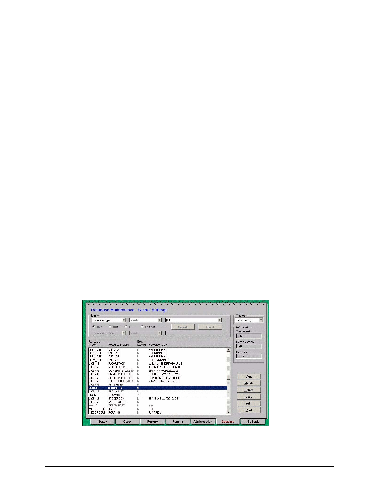
1. Enter the option keys in the OmniCenter application.
a. Click the Database tab, then select
b. Go to the Limits fields and select
c. Select Resource Subtype
RI ITEMS S, then click Modify.
Global Settings for Tables.
Resource Type, Equ als, License.
Figure 1-2. Database tab, Global Settings View—Resource Type Equals LICENSE List
OmniScanner Installation and Configuration Guide/60-0124 Rev F © 2010 Omnicell, Inc.
Page 7
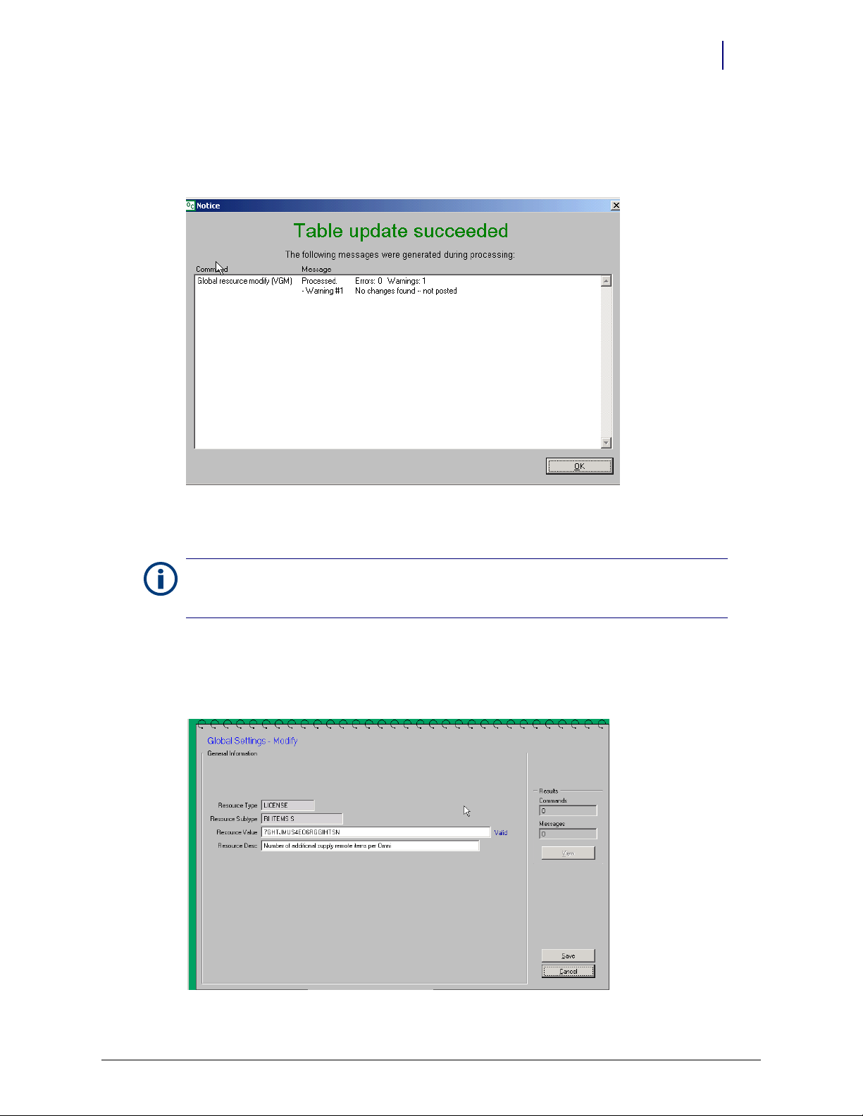
d. Go to the Resource Value field and enter the Remote Items Option Key.
e. Click Save.
f. Click OK on the update confirmation window.
Installation 1-3
Procedures
Figure 1-3. Save Confirmation
g. Click Go Back to return to the Global Settings list.
Note: If the entered Option Key is valid, the word “Valid” appears next to the Resource Value field once
Save is clicked. If the Option Key is incorrect or invalid, the word “Invalid” appears. If invalid, click Modify
to re-enter the Key.
h. Select Resource Subtype
RI OMNIS S, then click Modify.
i. Go to the Resource Value field and enter the Remote Items OmniSupplier Option Key.
j. Click Save.
Figure 1-4. Database tab, Global Settings View—Modify Resource Value
© 2010 Omnicell, Inc. OmniScanner Installation and Configuration Guide/60-0124 Rev F
Page 8
1-4 Installation
Procedures
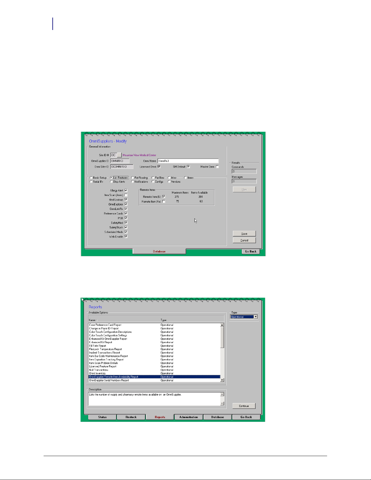
2. Enable remote items on the cabinets.
Once the appropriate Option Keys have been entered, the feature must be enabled on the
OmniSupplier record for each cabinet requiring the additional Remote Items.
a. Go to View Mode, then select the appropriate OmniSupplier from the table.
b. Select the Lic Features subtab (radio button).
c. Click Modify.
d. Go to the Remote Items section and select the Remote Item (S
) field.
e. Click Save.
Figure 1-5. Database tab, OmniSuppliers Modify
3. View the Remote Items Availability Report.
a. Click the Reports tab.
Figure 1-6. Report tab
OmniScanner Installation and Configuration Guide/60-0124 Rev F © 2010 Omnicell, Inc.
Page 9
b. Select Operational for the Type field.
c. Select
OmniSupplier Remote Items Availability Report for the Name field.
d. Click Continue.
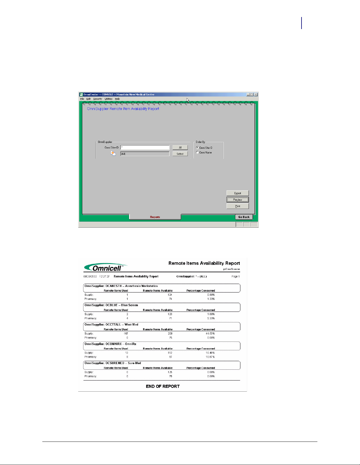
e. Specify OmniSupplier and order.
Installation 1-5
Procedures
Figure 1-7. Report Options
f. Click Print (for a hard copy) or Preview (to display the report on the screen).
Figure 1-8. Remote Item Availability Report
© 2010 Omnicell, Inc. OmniScanner Installation and Configuration Guide/60-0124 Rev F
Page 10
1-6 Installation
Procedures
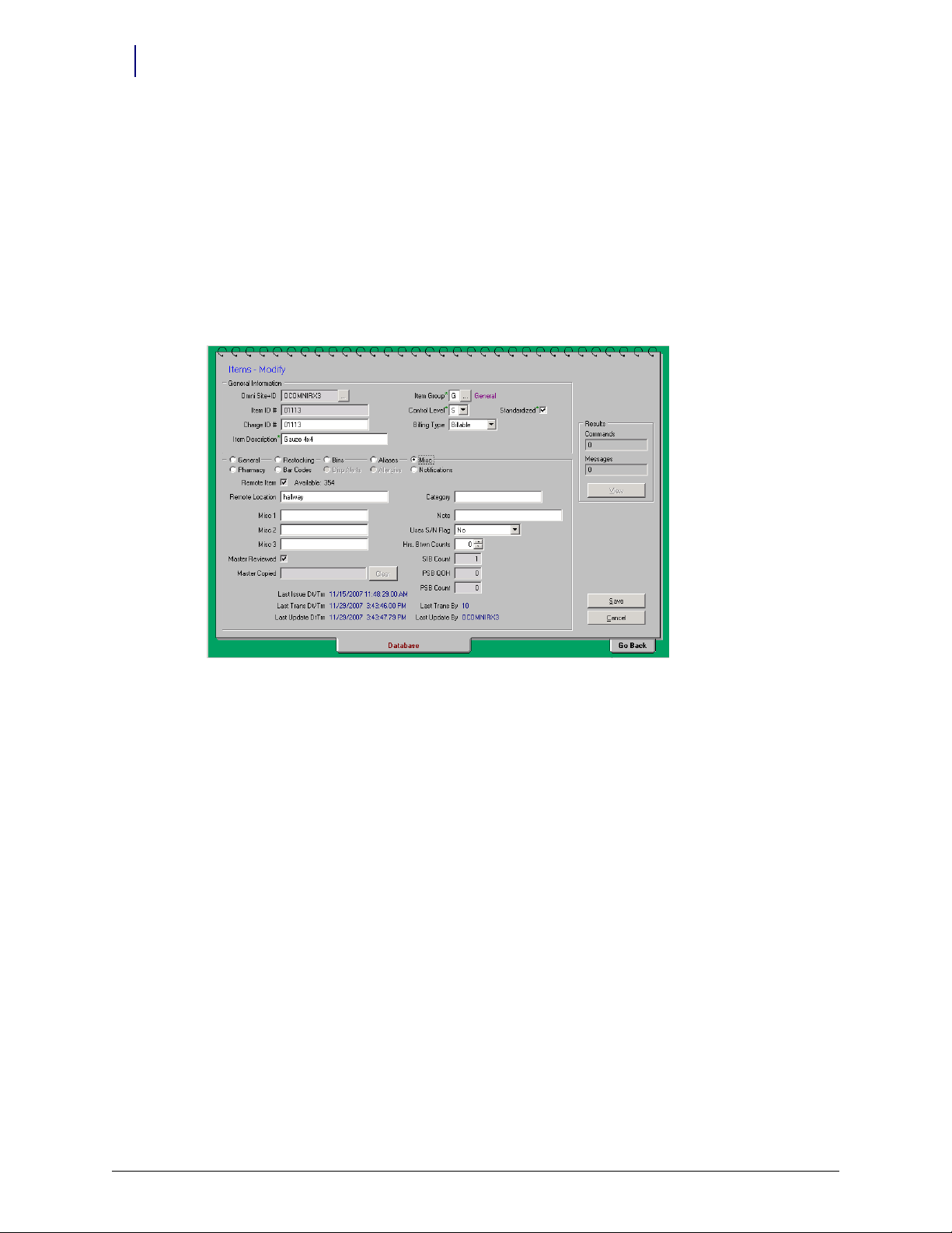
4. Assign items as remote items.
a. Click on the Database tab.
b. Select the Items table.
c. Click Search.
d. Click on the applicable item, then click Modify.
e. Select Misc. subtab (radio button).
f. Select the Remote Item field, then enter the location.
g. Click Save.
Figure 1-9. Database tab, Items Modify
OmniScanner Labels
Labels can only be set-up and printed from the OmniCenter.
1. Go to Administration tab > OmniSupplier Ty pe.
2. Select OmniSupplier Bin Labels.
3. Click Continue.
4. Select
5. Select the Omnisupplier name.
6. Select Supply under OmniSupplier.
7. Select the order by
8. Select the items
Remote - Avery for Label Type.
Item Name or Bin Number.
for which a label is needed by clicking on the item, then clicking Select or click
Select All.
OmniScanner Installation and Configuration Guide/60-0124 Rev F © 2010 Omnicell, Inc.
Page 11
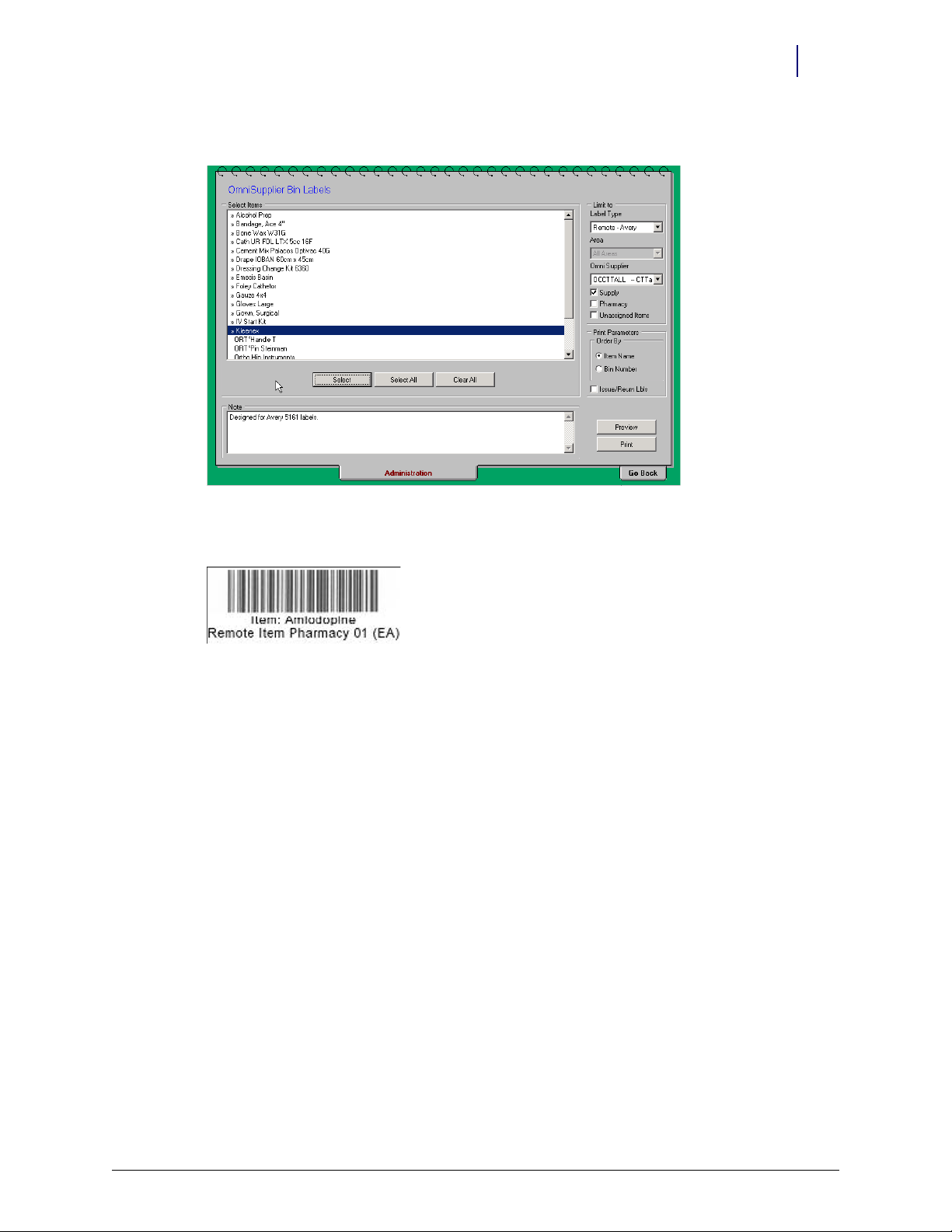
9. Click Preview to review label setup before printing.
Figure 1-10. Administration tab, OmniSupplier Bin Labels
Installation 1-7
Procedures
10. Click Print.
Figure 1-11. OmniScanner Bar Code
11. Create bar code labels for issue and return.
a. Go to Administration tab > OmniSupplier Ty pe .
b. Select OmniSupplier Bin Labels, then click Continue.
c. Select
Remote - Avery for Label Type.
d. Select the Omnisupplier name.
e. Select Supply under OmniSupplier.
f. Select the order by
Item Name or Bin Number.
© 2010 Omnicell, Inc. OmniScanner Installation and Configuration Guide/60-0124 Rev F
Page 12

1-8 Installation
Procedures
g. Select any item by clicking on the item, then clicking Select. The Issue and Return bar code
will not print without an item bar code selected to print.
h. Select Issue/Return Lbls.
Figure 1-12. OmniSupplier Bin Labels: Printing the Issue and Return bar codes
i. Click Preview to review label setup before printing.
j. Click Print.
Figure 1-13. Preview: Preview the Issue and Return bar code create Bar Code Labels for Issue and Return
OmniScanner Installation and Configuration Guide/60-0124 Rev F © 2010 Omnicell, Inc.
Page 13

OmniScanner Options
Installation 1-9
Procedures
Menu Name
Description
Value s
Default
Note
Table 1-1. Cabinet Type Configuration
Menu Name
Description
Value s
Default
Table 1-2. Items
Cabinet/Cradle Wiring
1. Power down the system and disconnect the power cord.
2. Put on an ESD wrist strap and secure it to ground.
3. Access the PC box.
Cabinet 0 Type
Designate the cabinet type
0-36
Var ies
For new and existing units, the Cabinet Type Configuration should already match the type of cabinet OmniScanner is
being installed on. For retrofit OmniScanner Color Touch Consoles, change the Cabinet Type to Color Touch Console
Omnicell Cabinet.
OmniScanner Support
Enables or disables OmniScanner support. Set this option to Yes, to enable OmniScanner functionality.
Yes / No
Nos
4. Plug both connectors of the Console-to-Keyboard cable (42-1201) to the USB Synapse cable.
.
Figure 1-14. USB cable connection with console-to-keyboard cable
© 2010 Omnicell, Inc. OmniScanner Installation and Configuration Guide/60-0124 Rev F
Page 14

1-10 Installation
auxiliary port
backplate cutout
Procedures
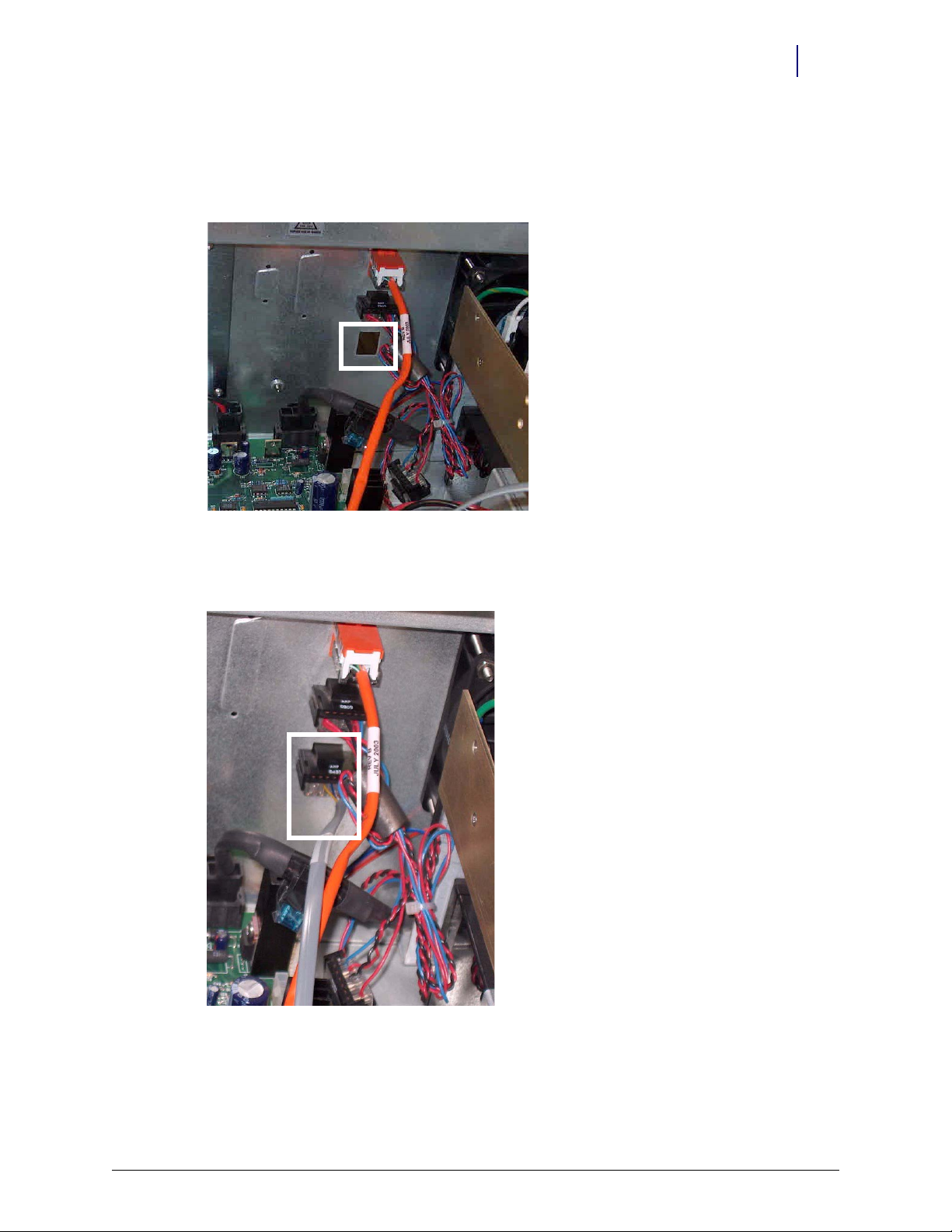
5. Attach the USB cable to the USB port on the motherboard.
.
Figure 1-15. USB connection to mother board
Note: There are two ways to connect the OmniScanner in back of the PC box depending on the model.
Older models use an auxiliary connector position. Newer models use a back plate (#53-1109) cutout to
save the auxiliary port.
Figure 1-16. Auxiliary Port vs. Backplate
OmniScanner Installation and Configuration Guide/60-0124 Rev F © 2010 Omnicell, Inc.
Page 15
Installation 1-11
Procedures
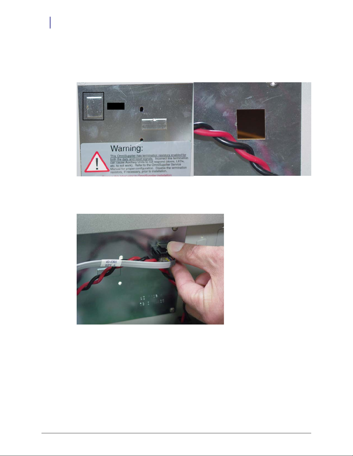
Older Color Touch PC Boxes
Use an auxiliary connector position for the OmniScanner cable.
1. Remove the bottom auxiliary connector from the sheet metal on the cabinet back.
.
Figure 1-17. Connector slot
2. Insert the port at the other end of the Console-to-Keyboard cable (42-1201) into the empty
auxiliary hole.
Figure 1-18. Scanner connector/internal cable
© 2010 Omnicell, Inc. OmniScanner Installation and Configuration Guide/60-0124 Rev F
Page 16
1-12 Installation
cutout
Procedures
Newer Color Touch PC Box with Backplate
Save the auxiliary port by using a backplate (#53-1109) cutout for the OmniScanner cable.
1. Punch out the backplate cutout.
Figure 1-19. Backplate cut out / Cutout punched out
2. Insert the port at the other end of the Console-to-Keyboard cable (42-1201) into the backplate
hole.
Figure 1-20. Connecting Console-to-Keyboard cable(#42-1201) to backplate
OmniScanner Installation and Configuration Guide/60-0124 Rev F © 2010 Omnicell, Inc.
Page 17
Installation 1-13
power
data port
Procedures
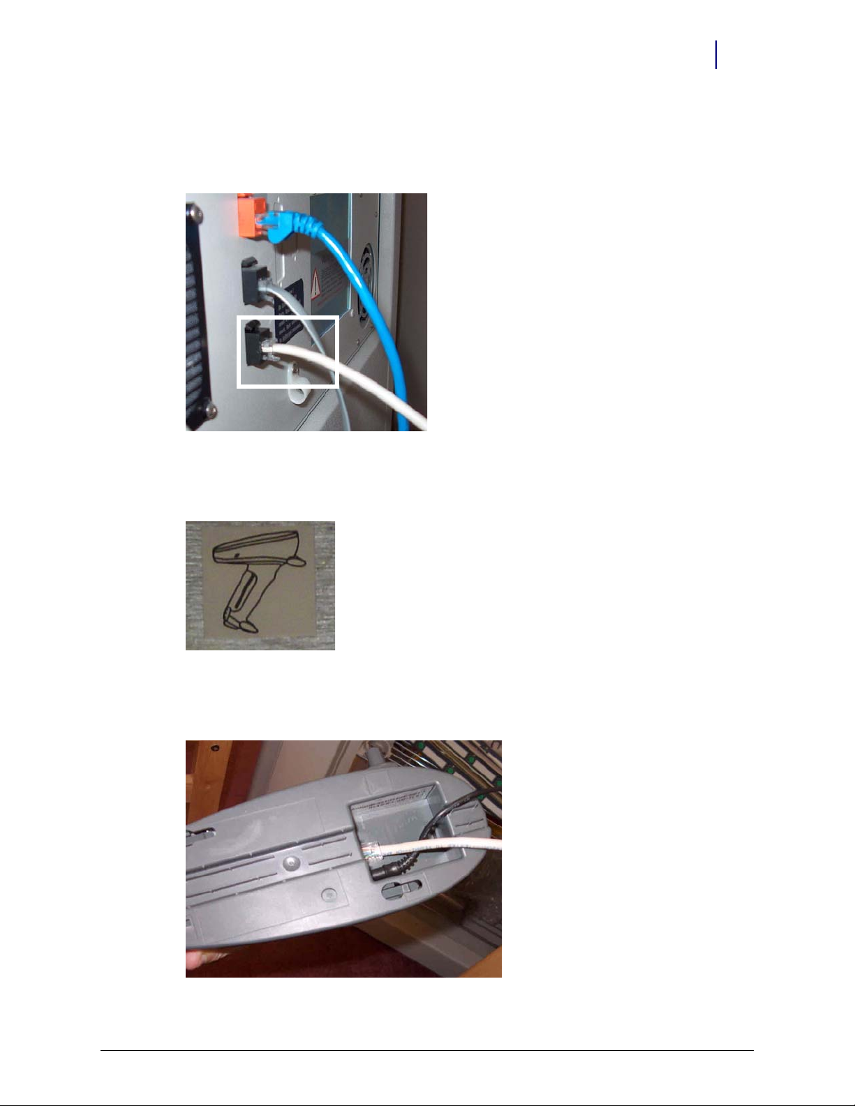
Cable Connection to the Cradle
1. Connect the six-wire RJ connector of the Scanner-to-Console cable (42-1200) to the Consoleto-Keyboard cable port (42-1201).
Figure 1-21. Scanner connector/external cable
2. Affix the scanner symbol label (#65-1057) on the back plate or PC box near the scanner
connector.
Figure 1-22. Scanner symbol sticker (#65-1057)
3. Plug the other end of the Scanner-to-Console cable (42-1200) into the RJ-45 data port of
scanner cradle.
Figure 1-23. Cradle connections
© 2010 Omnicell, Inc. OmniScanner Installation and Configuration Guide/60-0124 Rev F
Page 18
1-14 Installation
adapter
extension
Procedures
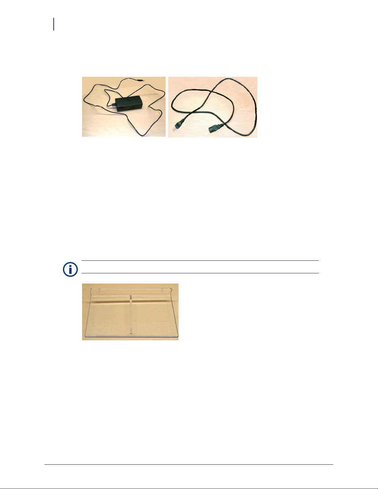
4. Plug the power adapter cord into the cradle base next to the RJ-45 port.
5. Connect the female end of the power extension to the power adapter cord.
Figure 1-24. Scanner power cable and adapter
6. Plug the male end of the power extension into a power outlet.
7. Secure the PC box in place.
8. Remove the ESD wrist strap.
9. Connect the cabinet power cord and power up the PC box.
Cradle Mounting
The cradle can be mounted to the cabinet, a wall or placed on a mounted shelf.
Shelf Mount
Note: Screws are not included with the wall mount (70-6030).
Figure 1-25. Shelf
1. Use two screws to secure the wall mount (shelf) to the wall.
2. Place the cradle on the wall mount.
3. Place the scanner in the cradle. Make sure the heel of the scanner is secure in the cradle.
4. Allow the scanner to charge for 4 hours before using.
OmniScanner Installation and Configuration Guide/60-0124 Rev F © 2010 Omnicell, Inc.
Page 19
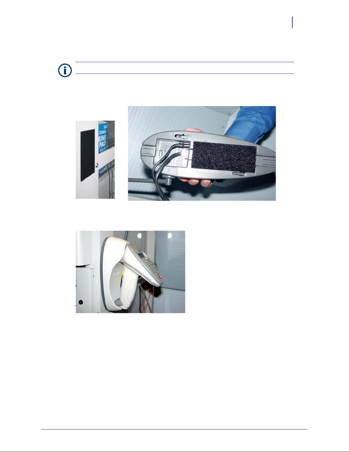
Cabinet Mount
Heavy-duty Velcro is not supplied with the kit.
Note:
1. Attach heavy-duty Velcro to the cabinet side with adhesive.
2. Attach heavy-duty Velcro to the bottom of the cradle with adhesive.
Installation 1-15
Procedures
Figure 1-26. Velcro applied to cabinet side and bottom of cradle
3. Attach the cradle to the Velcro on the cabinet.
Figure 1-27. Cradle secured to cabinet
4. lace the scanner in the cradle. Make sure the heel of the scanner is secure in the cradle.
© 2010 Omnicell, Inc. OmniScanner Installation and Configuration Guide/60-0124 Rev F
Page 20
1-16 Installation
screw slots
Procedures
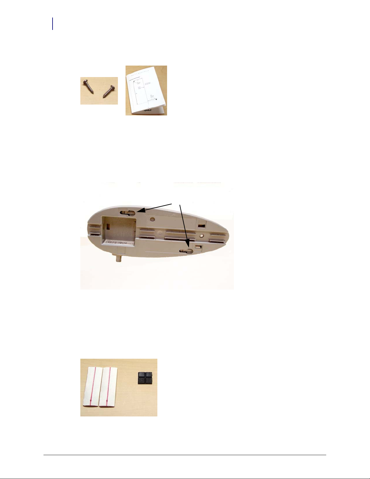
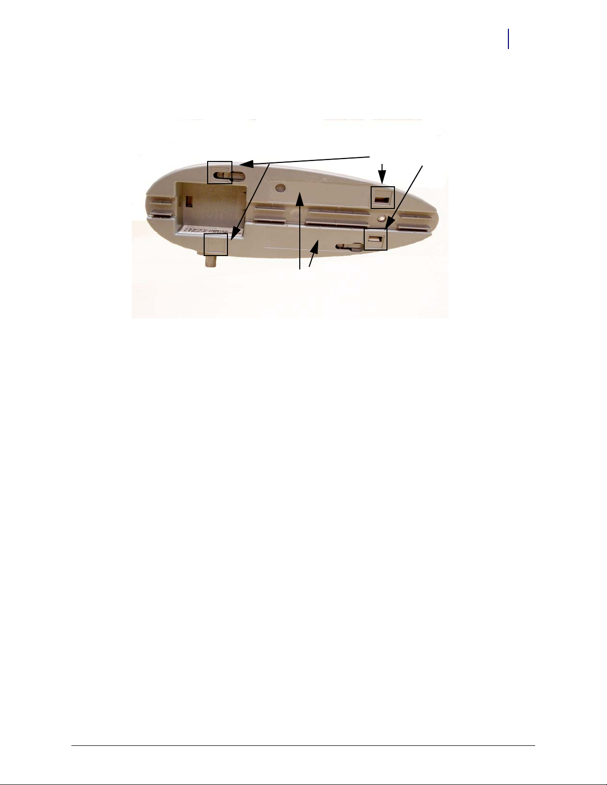
Cradle to Wall
Figure 1-28. Cradle screws and manufacturer instructions
1. Drill two screw holes into the wall using 1/8 drill bit according to the template in the scanner
documentation.
2. Insert and tighten the screws (supplied). The screw heads should extend from the wall.
3. Match the slots in the cradle back with the screw heads, then slide the cradle down over the
screw heads to secure the cradle.
Figure 1-29. Screw slots on bottom of cradle
4. Place the scanner in the cradle. Make sure the heel of the scanner is secure in the cradle
5. Allow the scanner to charge for 4 hours before using.
Cradle On Desk/Table
The cradle can be secured on a table or desk top using rubber feet or Velcro strips.
Figure 1-30. Velcro strips and rubber feet
OmniScanner Installation and Configuration Guide/60-0124 Rev F © 2010 Omnicell, Inc.
Page 21
Installation 1-17
feet indentions
Vel cro area s
Procedures
Rubber Feet. Attach four rubber feet (peel off adhesive cover) to the cradle bottom in the
designated indentions. The cradle can still be moved around on the desk or table surface.
Figure 1-31. Locations for feet or Velcro strips on bottom of cradle
Velcro Strips. The Velcro strips will anchor the cradle down in one spot on the table or desk
surface.
1. Attach Velcro strips (peel off adhesive cover) to bottom of cradle in the designated areas.
2. Attach Velcro strips to the desk top where the cradle is to be secured.
3. Align the Velcro strips on the cradle with those on the desk.
4. Press the cradle down to secure it.
Scanner Charging. The battery in the scanner may need charging.
1. Place the scanner in the cradle. Make sure the heel of the scanner is secure in the cradle
2. Allow the scanner to charge for 4 hours before using.
Scanner Pairing
1. Remove the scanner from the cradle.
2. Scan the pair barcode on the outside of the cradle or where the scanner nose is placed in the
cradle.
Connection Verification
1. Log in at the cabinet.
2. Press Diagnostics.
3. Press OmniScanner Diagnostics.
© 2010 Omnicell, Inc. OmniScanner Installation and Configuration Guide/60-0124 Rev F
Page 22
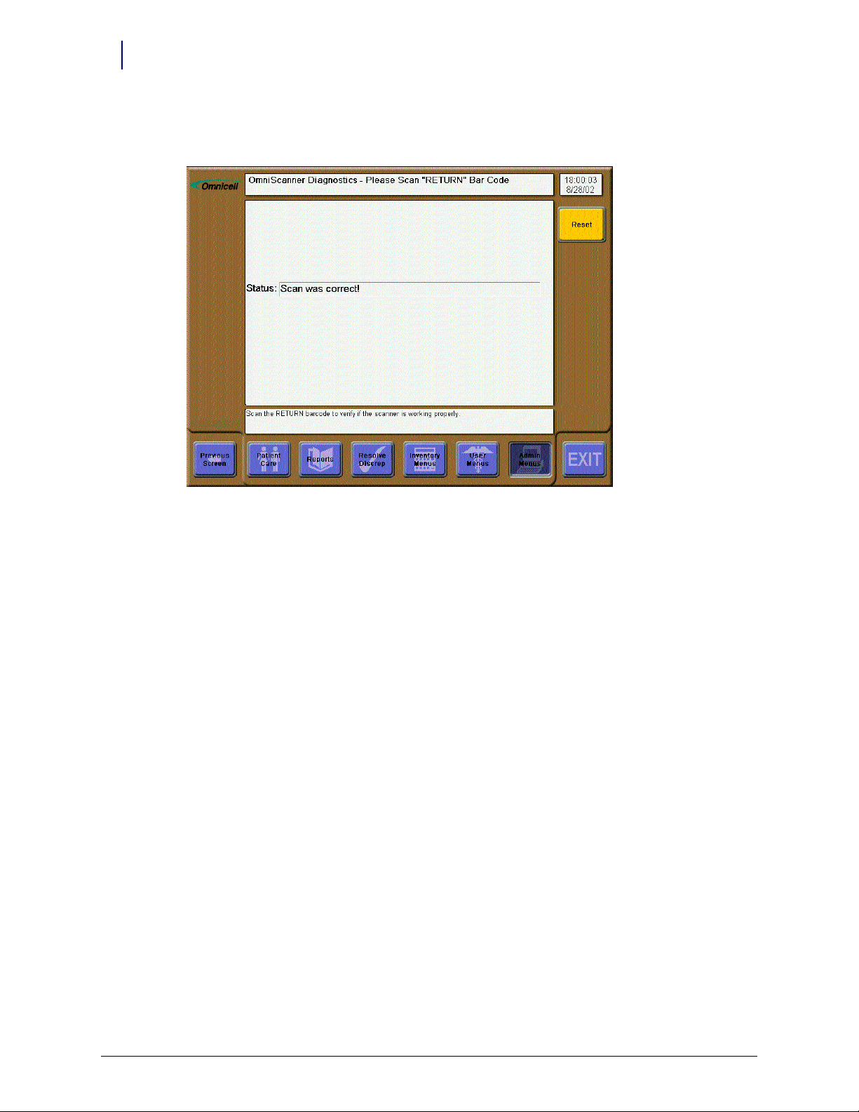
1-18 Installation
Version Upgrade
4. Press the down arrow button on the scanner or scan a Return barcode. The Status field should
Scan was correct!
read:
Figure 1-32. Diagnostic Menu - Scanner is enabled correctly
Connectivity Issues
If the Status field reads Wrong data scanned: Try again, scan a Return bar code.
If the Status field is blank, the hand held scanner may not be connected correctly.
1. Check the cradle wiring.
a. Disconnect the power cable.
b. Disconnect the communication cable.
c. Connect the communication cable.
d. Connect the power cable.
2. Re-initialize the scanner by pressing Func, then the star (*) keys.
3. Repeat the pairing process.
Version Upgrade
If upgrading from version1.0 to 2.0, see “Scanner Re-programming” on page 2-3. The scanner
version can be upgraded through re-programing.
OmniScanner Installation and Configuration Guide/60-0124 Rev F © 2010 Omnicell, Inc.
Page 23

Troubleshooting
Note:
The scanner is programmed at the factory. The scanner can be re-programmed in the field if necessary.
This chapter provides tests and response actions for specified conditions should the scanner not
work properly.
Communication Failure
If the scanner displays error messages after reading a bar code (sends no information to the
computer), perform a pairing of the scanner and its cradle.
1. Scan the PAIRING bar code on the cradle.
2. Place the scanner in the cradle and wait a few seconds for four short beeps.
If pairing fails, do the following steps:
a. Press the Func key then the * (asterisk/star) key to reset the scanner.
b. Scan the PAIRING bar code on the cradle.
c. Place the scanner in the cradle and wait a few seconds for four short beeps.
If pairing fails again, do the following steps:
a. Press the Func key then the * (asterisk/star) key to reset the scanner.
b. Disconnect the power cable from the cradle, then re-connect it.
c. Scan the PAIRING bar code on the cradle.
d. Place the scanner in the cradle and wait a few seconds for four short beeps.
If pairing still fails, do the following steps:
a. Press the Func key then the * (asterisk/star) key to reset the scanner.
b. Disconnect the serial cable from the cradle, then re-connect it.
c. Disconnect the power cable from the cradle, then re-connect it.
d. Scan the PAIRING bar code on the cradle.
e. Place the scanner in the cradle and wait a few seconds for four short beeps.
2-1
© 2010 Omnicell, Inc. OmniScanner Installation and Configuration Guide/60-0124 Rev F
Page 24
2-2 Troubleshooting
Programming Test
If the scanner reads a bar code with no errors, but the Color Touch software does not recognize
the item, do the following steps:
1. Go to the Color Touch OmniScanner Diagnostics window.
Note: The OmniScanner Support must be turned on from the Configuration / Items list.
a. Login as an OmniTech user.
b. Click on Diagnostics to display the general diagnostics window.
Figure 2-1. General Diagnostics window
OmniScanner Installation and Configuration Guide/60-0124 Rev F © 2010 Omnicell, Inc.
Page 25

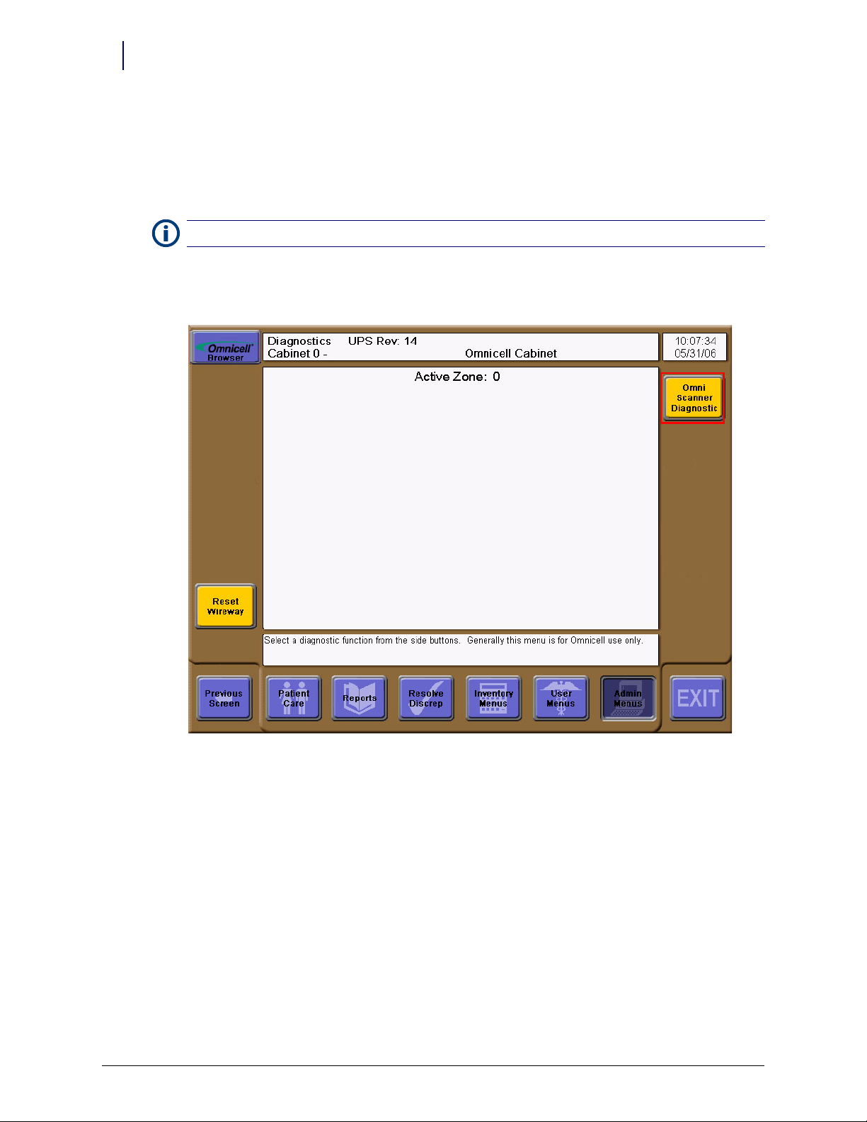
Troubleshooting 2-3
c. Click on OmniScanner Diagnostics to display the scanner diagnostics window.
Figure 2-2. Scanner Diagnostics
2. Scan the return label.
Important:
the “Scanner Re-programming” section.
If the Color Touch message says that the scanner is not programmed properly, follow the steps in
3. Click on Reset to clear the status.
4. Click on Previous Screen twice to return to the admin functions window.
Scanner Re-programming
Note: The re-programming steps can be used for upgrading an existing OmniScanner with version1.0
software to version 2.0.
Requirements
A special Symbol serial cable (#91-0009)
Symbol P370/P470 with cradle
© 2010 Omnicell, Inc. OmniScanner Installation and Configuration Guide/60-0124 Rev F
Page 26

2-4 Troubleshooting
Programming Station Setup
1. Insert the CD into the CR-ROM drive.
2. Open the CD drive, then double click on SBL_Link_W32_026003_lite.exe.
CD #30-1000
SBL_LINK_W32_026003_LITE.EXE
Omni2.PRJ folder
or files downloaded from Agile:
SBL_LINK_W32_026003_LITE.EXE
Omni2.PRJ.ZIP
Figure 2-3. Accessing the CD Drive
3. Accept all defaults. It installs the Link Lite program into C:\MCL\PHASER\linklite_2.60.03.
Figure 2-4. Starting the MCL linklite installation
OmniScanner Installation and Configuration Guide/60-0124 Rev F © 2010 Omnicell, Inc.
Page 27
Troubleshooting 2-5
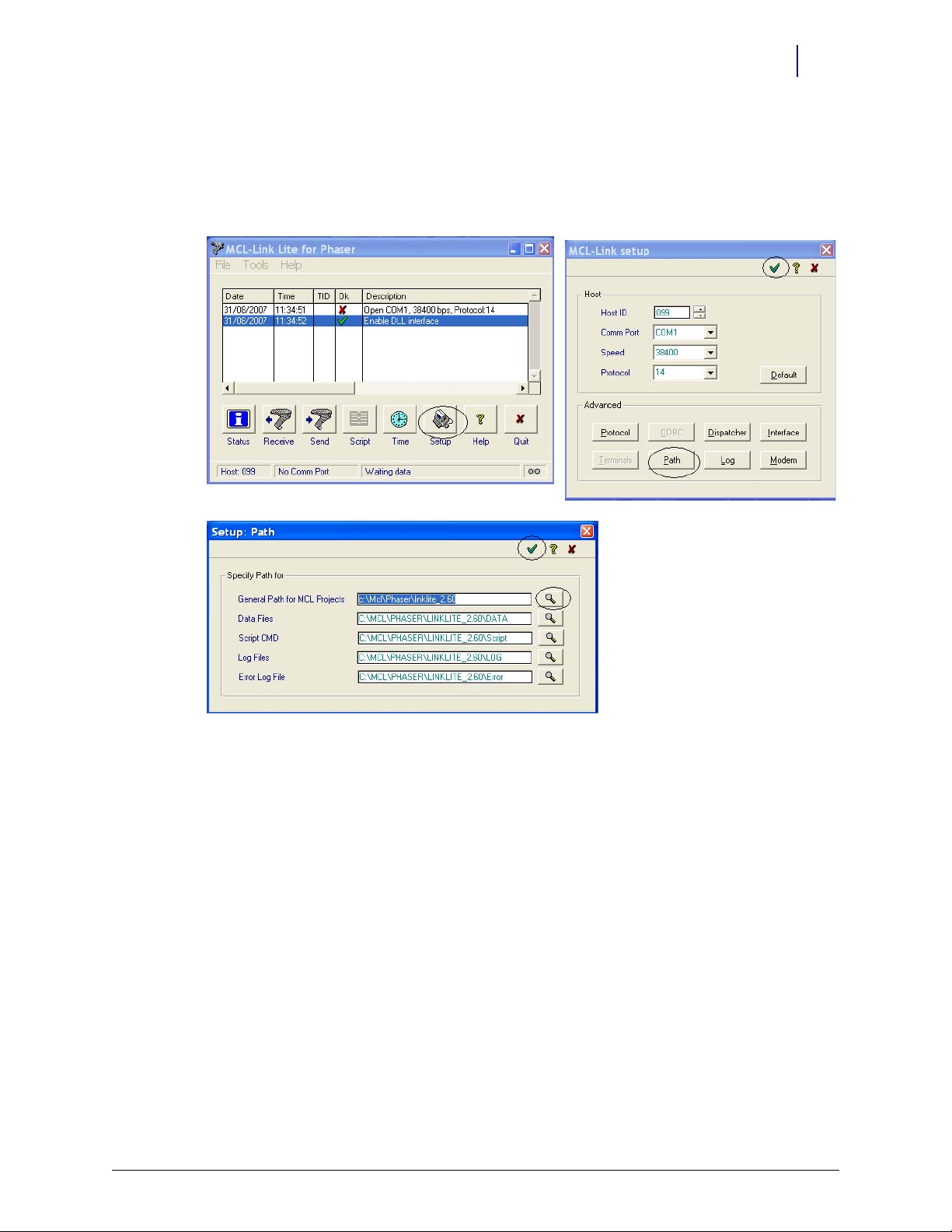
4. In the MCL-Link Lite for Phaser window, click Setup and then path. Verify that the General
Path for MCL Projects is as follows:
5. Use the browser (magnifying glass icon) to locate correct path if necessary.
6. Click the green arrow to accept the selection.
C:\MCL\PHASER\LINKLITE_2.60
Figure 2-5. MCL-Link, Path windows
7. Copy Omni2.PRJ folder From the CD drive into the following directory:
C:\MCL\PHASER\LINKLITE_2.60
8. If using files from Agile, unzip and drag the folder into the C:\MCL\PHASER\LINKLITE_2.60 directory
path.
9. Attach the special serial cable to the computer’s COM port and the scanner cradle.
10. Plug in the cradle’s power cable.
11. Place the scanner in its cradle and allow at least 1 hour for charging prior to programming.
Scanner Programming
1. Pair the scanner with its cradle.
a. Scan the PAIRING bar code on the cradle.
b. Place the scanner in the cradle and wait a few seconds for four short beeps.
2. Double click mcllink.exe in the C:\MCL\PHASER\linklite_2.60.03 directory.
3. If Open COMx (x is the port number), 38400 bps, Protocol 14 is accepted with a green check,
go to step 5.
© 2010 Omnicell, Inc. OmniScanner Installation and Configuration Guide/60-0124 Rev F
Page 28

2-6 Troubleshooting
4. If Open COMx, 38400 bps, Protocol 14 is not connected and a red X appears, do the following
steps:
a. Select Setup.
b. Change Comm Port to the appropriate communication port—every computer is different.
c. Select the green check to accept. The screen shots below illustrate a COM4 setup.
Figure 2-6. MCL Link Setup
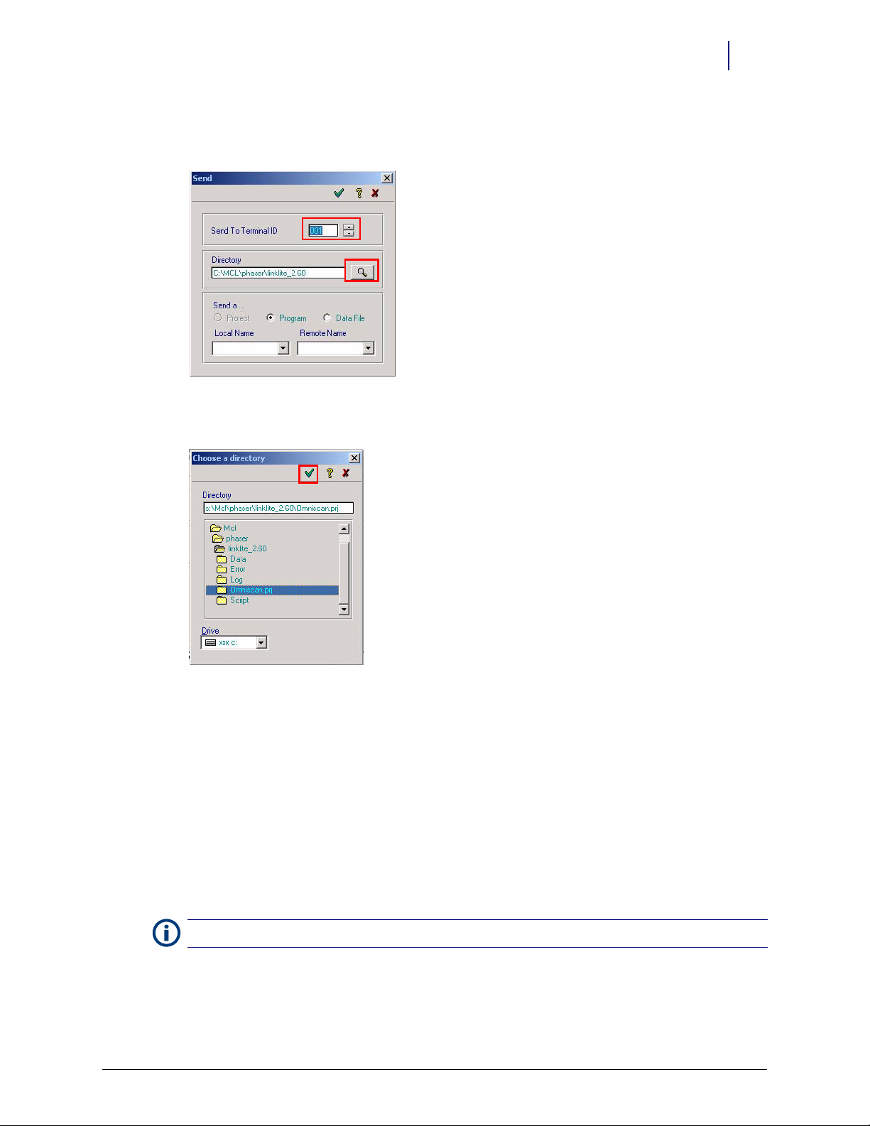
5. Select Send File from the Tools menu or the Send screen button.
Figure 2-7. Using the MCL linklite window
6. Make sure the proper COM port is selected.
OmniScanner Installation and Configuration Guide/60-0124 Rev F © 2010 Omnicell, Inc.
Page 29
Troubleshooting 2-7
step #4
step #5
7. Click on the browse button (with icon of magnifying glass) to find Omni2.prj. The file path
should be: c:/mcl/phaser/linklite_2.60.03/Omni2.prj
Figure 2-8. Opening the Send window
8. Click on the green check mark to select omniscan.prj.
Figure 2-9. Using the Search window
9. Place the scanner into download mode.
a. Press the Func key, then immediately press the * (asterisk/star) key.
b. Quickly press the Func key again, then the BK key.
c. Press the down arrow key to go from
System Setup to App Control.
d. Press the Enter key to see Load App menu item.
e. Press the Enter key again to see the Load New App menu item.
f. Press the Enter key again to initiate load mode.
g. Place the scanner in the cradle, then quickly press the green check mark in the Send
window [Figure 2-8].
Note:
It takes a few seconds for the download to be completed. The scanner will then reset itself.
© 2010 Omnicell, Inc. OmniScanner Installation and Configuration Guide/60-0124 Rev F
Page 30

2-8 Troubleshooting
Program Revision Check
1. Press the Func key then the * (asterisk/star) key to reset the scanner.
2. Look for the program revision which displays briefly when the program is re-started.
This concludes the programming procedure for a properly functioning scanner.
Important:
back to the default application setting (steps below) before re-starting the programming steps.
If there is a problem during programming and the scanner stops functioning properly, go
Default Application Setting
1. Press the Func key, then press the * (asterisk/star) key.
2. Quickly press the Func key again, then the BK key.
3. Press the down arrow key to go from
4. Press the Enter key, to see Load App menu item.
5. Press the down arrow key to go from
6. Press the Enter key to go from
7. Press the Enter key again to reset the default app, or press the BK key to cancel.
System Setup to App Control.
Load App to Set Default App.
Set Default App to Reset Default App?
OmniScanner Installation and Configuration Guide/60-0124 Rev F © 2010 Omnicell, Inc.
Page 31

Parts List
The following kits make up the OmniScanner assembly.
Kit # Item # Item Description Notes Qty
12-6014 OmniScanner Manufacturing Assembly
12-1254 Mfg. programmed Scanner Kit 1
42-1200 Console to Scanner Cable 1
42-1201 Keyboard to Console Cable 1
60-0132 OmniScanner 2.0 User Guide 1
65-1057 Scanner Console Label 1
88-0022 USB Synapse Cable 1
Table A-1. Kit # 12-6014
A-1
Kit # Item # Item Description Notes Qty
20-6000 Symbol P370 Scanner Kit cordless, handheld, RSS
70-0900 Scanner Cradle RSS Firmware 1
70-6050 P370 Scanner 1
74-1038 Power Supply Adapter 90-264V AC, 9V DC 2A, EPS, 2 Pos, ROHS 1
74-1039 Power Cord 6 ft., 18 AWG, ROHS 1
74-2001 Battery Pack 3.6V, 1620, P/N SY47L1-E 1
Table A-2. Kit # 20-6000
Kit # Item # Item Description Notes Qty
20-0122 KIT, P370 Scanner, Field Upgrade OmniScanner version, RSS
20-0117 KIT, P370 Scanner, Field Upgrade Non-OmniScanner version, RSS 1
30-1002 MCL Link Lite (2.0 software) with data files 1
60-0124 OmniScanner Installation Guide + troubleshooting 0
91-0009 RS232 Cable for Symbol P370/P470 1
Table A-3. Kit #20-0122 -RSS Upgrade Kit
The Rioux mounting shelf (70-6030) must be ordered separately. Velcro squares for cabinet
mounting is not available through Omnicell—it must be purchased from a third party. The
scanner cradle does comes with screws for wall mounting or feet tabs/Velcro strips for sitting on a
desk/table.
© 2010 Omnicell, Inc. OmniScanner Installation and Configuration Guide/60-0124 Rev F
Page 32

A-2 Parts List
OmniScanner Installation and Configuration Guide/60-0124 Rev F © 2010 Omnicell, Inc.
Page 33

Index
D
default application setting 2-8
I
installation
overview 1-1
procedures 1-2
requirements 1-1
O
OmniCenter settings 1-2
OmniScanner options 1-9
IN-1
P
parts list A-1
program revision check 2-8
programming station setup 2-4
R
requirements
reprogramming 2-3
software 1-1
tools 1-1
S
scanner re-programming 2-3
© 2010 Omnicell, Inc. OmniScanner Installation and Configuration Guide/60-0124 Rev F
Page 34

IN-2 Index
OmniScanner Installation and Configuration Guide/60-0124 Rev F © 2010 Omnicell, Inc.
Page 35

Documentation Feedback
This document is designed to provide relevant technical information to those responsible for the
implementation, service, and support of Omnicell products. The Documentation team needs your
input, so we can continue to improve our publications.
Sending Comments to the Technical Documentation Team
Did this document meet your needs? If so, please let us know what we’re doing right. If not, please
provide specific feedback. E-mail or fax your feedback as follows:
E-mail: Documentation Requests e-mail group at documentationrequests@omnicell.com (specify the
document title or PN).
Fax: Send this page, along with your feedback, to (650) 251-6266, attention: Documentation.
This document is designed to provide relevant technical information to Omnicell personnel
responsible for the implementation, service, and support of Omnicell Automation Systems.
Feedback Form
Name: E-mail:
Dept./Title: Phone:
Feed back:
© 2010 Omnicell, Inc. OmniScanner Installation and Configuration Guide/60-0124 Rev F
Page 36

 Loading...