

Page 1

OmniDispenser
Technical
Guide
60-3007 Rev G
Includes hardware,
software, and
implementation steps
Page 2

This guide is CONFIDENTIAL and designed only for Omnicell Technical personnel and/or designated
representatives.
This guide and accompanying software and/or hardware described in it are protected under copyright laws and may
not be copied, wholly or in part, without the express written consent of Omnicell, Inc. The same proprietary and
copyright notices must be attached to any permitted copies as were attached to the original documents.
Omnicell, Inc.
1201 Charleston Road
Mountain View, CA 94043
(650) 251-6100
www.omnicell.com
Omnicell and the Omnicell design mark, OmniBuyer, OmniCenter, OmniRx, OmniSupplier, SafetyMed, SafetyPak,
SafetyStock, and Sure-Med are registered trademarks. Anesthesia TT, Anesthesia Workstation, Anywhere RN,
Executive Advisor, Flexbin, Medication Surveillance, OmniDispenser, OmniLinkRx, OmniScanner, OmniTrack,
Omni TT, Open Touch, OptiFlex, OptiFlex MobileTrack, Point-to-Point Medication Safety, SecureVault, See & Touch,
SinglePointe, TempCheck, Touch & Go, VSuite, and WorkflowRx are trademarks of Omnicell, Inc. in the United States
and internationally. All other trademarks and trade names are the property of their respective owners
Copyright 2009-2012 Omnicell, Inc. All rights reserved.
OmniDispenser Technical Guide/60-3007 Rev G © 2012 Omnicell, Inc.
Page 3

iii
Table of Contents
Introduction . . . . . . . . . . . . . . . . . . . . . . . . . . . . . . . . . . . . . . . . . . . . . . . . . . . . . . . . . . . . . . . . . 1-1
About This Guide . . . . . . . . . . . . . . . . . . . . . . . . . . . . . . . . . . . . . . . . . . . . . . . . . . . . . . . . . . . . 1-1
Product Overview . . . . . . . . . . . . . . . . . . . . . . . . . . . . . . . . . . . . . . . . . . . . . . . . . . . . . . . . . . . . 1-1
Competitive Advantages . . . . . . . . . . . . . . . . . . . . . . . . . . . . . . . . . . . . . . . . . . . . . . . . . . . 1-1
Requirements. . . . . . . . . . . . . . . . . . . . . . . . . . . . . . . . . . . . . . . . . . . . . . . . . . . . . . . . . . . . . 1-1
Hardware . . . . . . . . . . . . . . . . . . . . . . . . . . . . . . . . . . . . . . . . . . . . . . . . . . . . . . . . . . . . 1-2
Software. . . . . . . . . . . . . . . . . . . . . . . . . . . . . . . . . . . . . . . . . . . . . . . . . . . . . . . . . . . . . . 1-2
Technical Overview. . . . . . . . . . . . . . . . . . . . . . . . . . . . . . . . . . . . . . . . . . . . . . . . . . . . . . . . . . . 2-1
Hardware Components . . . . . . . . . . . . . . . . . . . . . . . . . . . . . . . . . . . . . . . . . . . . . . . . . . . . . . . 2-1
Dispense Drawer . . . . . . . . . . . . . . . . . . . . . . . . . . . . . . . . . . . . . . . . . . . . . . . . . . . . . . . . . . 2-1
Restock Door . . . . . . . . . . . . . . . . . . . . . . . . . . . . . . . . . . . . . . . . . . . . . . . . . . . . . . . . . . . . . 2-1
Restock Compartment . . . . . . . . . . . . . . . . . . . . . . . . . . . . . . . . . . . . . . . . . . . . . . . . . . . . . 2-2
Rail Frame. . . . . . . . . . . . . . . . . . . . . . . . . . . . . . . . . . . . . . . . . . . . . . . . . . . . . . . . . . . . 2-2
Rails (Fixed and Optional) . . . . . . . . . . . . . . . . . . . . . . . . . . . . . . . . . . . . . . . . . . . . . . 2-2
Dispensers. . . . . . . . . . . . . . . . . . . . . . . . . . . . . . . . . . . . . . . . . . . . . . . . . . . . . . . . . . . . 2-2
System Information . . . . . . . . . . . . . . . . . . . . . . . . . . . . . . . . . . . . . . . . . . . . . . . . . . . . . . . . . . 2-3
Drawer Type and Name . . . . . . . . . . . . . . . . . . . . . . . . . . . . . . . . . . . . . . . . . . . . . . . . . . . . 2-3
Module Placement . . . . . . . . . . . . . . . . . . . . . . . . . . . . . . . . . . . . . . . . . . . . . . . . . . . . . . . . 2-3
ODMTall and ODMPlus3 Placement Rules . . . . . . . . . . . . . . . . . . . . . . . . . . . . . . . 2-3
ODMRx Placement Rules. . . . . . . . . . . . . . . . . . . . . . . . . . . . . . . . . . . . . . . . . . . . . . . 2-4
Rail Configuration. . . . . . . . . . . . . . . . . . . . . . . . . . . . . . . . . . . . . . . . . . . . . . . . . . . . . . . . . 2-5
Options/Rules. . . . . . . . . . . . . . . . . . . . . . . . . . . . . . . . . . . . . . . . . . . . . . . . . . . . . . . . . 2-5
Automatic Rail Configuration Detection. . . . . . . . . . . . . . . . . . . . . . . . . . . . . . . . . . 2-5
Communication with OmniCenter . . . . . . . . . . . . . . . . . . . . . . . . . . . . . . . . . . . . . . 2-6
Dispenser Configuration Options. . . . . . . . . . . . . . . . . . . . . . . . . . . . . . . . . . . . . . . . 2-6
Addressing Scheme. . . . . . . . . . . . . . . . . . . . . . . . . . . . . . . . . . . . . . . . . . . . . . . . . . . . . . . . 2-6
Location Description . . . . . . . . . . . . . . . . . . . . . . . . . . . . . . . . . . . . . . . . . . . . . . . . . . . . . . 2-7
Dispensing Behavior. . . . . . . . . . . . . . . . . . . . . . . . . . . . . . . . . . . . . . . . . . . . . . . . . . . . . . . 2-7
Dispense Drawer . . . . . . . . . . . . . . . . . . . . . . . . . . . . . . . . . . . . . . . . . . . . . . . . . . . . . . 2-7
Multiple OmniDispensers . . . . . . . . . . . . . . . . . . . . . . . . . . . . . . . . . . . . . . . . . . . . . . 2-7
FIFO for Multiple Bins . . . . . . . . . . . . . . . . . . . . . . . . . . . . . . . . . . . . . . . . . . . . . . . . . 2-7
Dispense Errors . . . . . . . . . . . . . . . . . . . . . . . . . . . . . . . . . . . . . . . . . . . . . . . . . . . . . . . 2-8
Dispense Transactions . . . . . . . . . . . . . . . . . . . . . . . . . . . . . . . . . . . . . . . . . . . . . . . . . 2-8
Returning Medications. . . . . . . . . . . . . . . . . . . . . . . . . . . . . . . . . . . . . . . . . . . . . . . . . . . . . 2-8
Time-out Behavior . . . . . . . . . . . . . . . . . . . . . . . . . . . . . . . . . . . . . . . . . . . . . . . . . . . . . . . . 2-9
Please Open Dispense Drawer Time-out . . . . . . . . . . . . . . . . . . . . . . . . . . . . . . . . . . 2-9
Please Open Restock Door Time-out . . . . . . . . . . . . . . . . . . . . . . . . . . . . . . . . . . . . . 2-9
Forced Entry Detection . . . . . . . . . . . . . . . . . . . . . . . . . . . . . . . . . . . . . . . . . . . . . . . . . . . . 2-9
Inactive Access. . . . . . . . . . . . . . . . . . . . . . . . . . . . . . . . . . . . . . . . . . . . . . . . . . . . . . . . . . . . 2-9
EEPROM Configuration Settings . . . . . . . . . . . . . . . . . . . . . . . . . . . . . . . . . . . . . . . . . . . . 2-9
© 2012 Omnicell, Inc. OmniDispenser Technical Guide/60-3007 Rev G
Page 4

iv Table of Contents
Software Functional Overview . . . . . . . . . . . . . . . . . . . . . . . . . . . . . . . . . . . . . . . . . . . . . . . . 3-1
Automatic Diagnostics. . . . . . . . . . . . . . . . . . . . . . . . . . . . . . . . . . . . . . . . . . . . . . . . . . . . . . . . 3-1
Color Touch Functionality . . . . . . . . . . . . . . . . . . . . . . . . . . . . . . . . . . . . . . . . . . . . . . . . . . . . 3-1
Diagnostics. . . . . . . . . . . . . . . . . . . . . . . . . . . . . . . . . . . . . . . . . . . . . . . . . . . . . . . . . . . . . . . 3-1
Restock Door Behavior . . . . . . . . . . . . . . . . . . . . . . . . . . . . . . . . . . . . . . . . . . . . . . . . . 3-1
Dispenser Drawer Behavior . . . . . . . . . . . . . . . . . . . . . . . . . . . . . . . . . . . . . . . . . . . . . 3-3
Dispenser Behavior . . . . . . . . . . . . . . . . . . . . . . . . . . . . . . . . . . . . . . . . . . . . . . . . . . . . 3-4
Dispense Function. . . . . . . . . . . . . . . . . . . . . . . . . . . . . . . . . . . . . . . . . . . . . . . . . . . . . 3-5
Empty Dispenser Function. . . . . . . . . . . . . . . . . . . . . . . . . . . . . . . . . . . . . . . . . . . . . . 3-5
Reset Wireway and Module Function . . . . . . . . . . . . . . . . . . . . . . . . . . . . . . . . . . . . 3-6
Internal Bus Communications Diagnostics. . . . . . . . . . . . . . . . . . . . . . . . . . . . . . . . 3-6
Dispense Setup Diagnostics . . . . . . . . . . . . . . . . . . . . . . . . . . . . . . . . . . . . . . . . . . . . . 3-7
Firmware Revision Diagnostics. . . . . . . . . . . . . . . . . . . . . . . . . . . . . . . . . . . . . . . . . . 3-8
Emitter Full Diagnostics . . . . . . . . . . . . . . . . . . . . . . . . . . . . . . . . . . . . . . . . . . . . . . . . 3-9
Check Stuck Buttons . . . . . . . . . . . . . . . . . . . . . . . . . . . . . . . . . . . . . . . . . . . . . . . . . . 3-10
Emitter Bank Diagnostics. . . . . . . . . . . . . . . . . . . . . . . . . . . . . . . . . . . . . . . . . . . . . . 3-11
Normal Restock. . . . . . . . . . . . . . . . . . . . . . . . . . . . . . . . . . . . . . . . . . . . . . . . . . . . . . . . . . 3-12
Supplemental Restock. . . . . . . . . . . . . . . . . . . . . . . . . . . . . . . . . . . . . . . . . . . . . . . . . . . . . 3-13
Destock . . . . . . . . . . . . . . . . . . . . . . . . . . . . . . . . . . . . . . . . . . . . . . . . . . . . . . . . . . . . . . . . . 3-14
Cycle Count . . . . . . . . . . . . . . . . . . . . . . . . . . . . . . . . . . . . . . . . . . . . . . . . . . . . . . . . . . . . . 3-14
Expiration/Recall. . . . . . . . . . . . . . . . . . . . . . . . . . . . . . . . . . . . . . . . . . . . . . . . . . . . . . . . . 3-15
Modify Bin . . . . . . . . . . . . . . . . . . . . . . . . . . . . . . . . . . . . . . . . . . . . . . . . . . . . . . . . . . . . . . 3-15
Select a Bin . . . . . . . . . . . . . . . . . . . . . . . . . . . . . . . . . . . . . . . . . . . . . . . . . . . . . . . . . . 3-16
Assigning an Item . . . . . . . . . . . . . . . . . . . . . . . . . . . . . . . . . . . . . . . . . . . . . . . . . . . . 3-17
Replacing an Item Assignment . . . . . . . . . . . . . . . . . . . . . . . . . . . . . . . . . . . . . . . . . 3-17
Deleting an Item Assignment . . . . . . . . . . . . . . . . . . . . . . . . . . . . . . . . . . . . . . . . . . 3-18
Unassigning All Bins. . . . . . . . . . . . . . . . . . . . . . . . . . . . . . . . . . . . . . . . . . . . . . . . . . 3-18
Setting Bin Level . . . . . . . . . . . . . . . . . . . . . . . . . . . . . . . . . . . . . . . . . . . . . . . . . . . . . 3-18
Countback Always Configuration . . . . . . . . . . . . . . . . . . . . . . . . . . . . . . . . . . . . . . . . . . 3-19
OmniCenter Functionality . . . . . . . . . . . . . . . . . . . . . . . . . . . . . . . . . . . . . . . . . . . . . . . . . . . 3-20
User Access to Restock Door. . . . . . . . . . . . . . . . . . . . . . . . . . . . . . . . . . . . . . . . . . . . . . . 3-20
Reports . . . . . . . . . . . . . . . . . . . . . . . . . . . . . . . . . . . . . . . . . . . . . . . . . . . . . . . . . . . . . . . . . 3-20
Pharmacy Drawer Configuration Report. . . . . . . . . . . . . . . . . . . . . . . . . . . . . . . . . 3-20
Dispensing Error Report. . . . . . . . . . . . . . . . . . . . . . . . . . . . . . . . . . . . . . . . . . . . . . . 3-20
Message Alerts . . . . . . . . . . . . . . . . . . . . . . . . . . . . . . . . . . . . . . . . . . . . . . . . . . . . . . . . . . . 3-21
Forced Entry Detection. . . . . . . . . . . . . . . . . . . . . . . . . . . . . . . . . . . . . . . . . . . . . . . . 3-21
Message Filter Setup . . . . . . . . . . . . . . . . . . . . . . . . . . . . . . . . . . . . . . . . . . . . . . . . . . 3-21
Implementation . . . . . . . . . . . . . . . . . . . . . . . . . . . . . . . . . . . . . . . . . . . . . . . . . . . . . . . . . . . . . 4-1
Overview . . . . . . . . . . . . . . . . . . . . . . . . . . . . . . . . . . . . . . . . . . . . . . . . . . . . . . . . . . . . . . . . . . . . 4-1
Configuring Rails . . . . . . . . . . . . . . . . . . . . . . . . . . . . . . . . . . . . . . . . . . . . . . . . . . . . . . . . . . . . 4-1
Install a Rail . . . . . . . . . . . . . . . . . . . . . . . . . . . . . . . . . . . . . . . . . . . . . . . . . . . . . . . . . . . . . . 4-2
Remove a Rail . . . . . . . . . . . . . . . . . . . . . . . . . . . . . . . . . . . . . . . . . . . . . . . . . . . . . . . . . . . . 4-3
Adjusting Dispensers . . . . . . . . . . . . . . . . . . . . . . . . . . . . . . . . . . . . . . . . . . . . . . . . . . . . . . . . . 4-3
Installing Dispensers . . . . . . . . . . . . . . . . . . . . . . . . . . . . . . . . . . . . . . . . . . . . . . . . . . . . . . . . . 4-5
Labeling Dispensers . . . . . . . . . . . . . . . . . . . . . . . . . . . . . . . . . . . . . . . . . . . . . . . . . . . . . . . . . . 4-6
OmniDispenser Technical Guide/60-3007 Rev G © 2012 Omnicell, Inc.
Page 5

Table of Contents v
Loading Dispensers. . . . . . . . . . . . . . . . . . . . . . . . . . . . . . . . . . . . . . . . . . . . . . . . . . . . . . . . . . . 4-6
Oral Solids . . . . . . . . . . . . . . . . . . . . . . . . . . . . . . . . . . . . . . . . . . . . . . . . . . . . . . . . . . . . . . . 4-6
Select a Cassette . . . . . . . . . . . . . . . . . . . . . . . . . . . . . . . . . . . . . . . . . . . . . . . . . . . . . . . 4-6
Loading the Cassette . . . . . . . . . . . . . . . . . . . . . . . . . . . . . . . . . . . . . . . . . . . . . . . . . . . 4-8
Syringes. . . . . . . . . . . . . . . . . . . . . . . . . . . . . . . . . . . . . . . . . . . . . . . . . . . . . . . . . . . . . . . . . . 4-9
Vials and Ampules . . . . . . . . . . . . . . . . . . . . . . . . . . . . . . . . . . . . . . . . . . . . . . . . . . . . . . . 4-10
Selecting a Vial/Ampule Cassette or Dispenser . . . . . . . . . . . . . . . . . . . . . . . . . . . 4-10
Loading a Vial/Ampule Cassette . . . . . . . . . . . . . . . . . . . . . . . . . . . . . . . . . . . . . . . . 4-10
Loading a Vial/Ampule Dispenser . . . . . . . . . . . . . . . . . . . . . . . . . . . . . . . . . . . . . . 4-11
Configuring Cabinet Software . . . . . . . . . . . . . . . . . . . . . . . . . . . . . . . . . . . . . . . . . . . . . . . . 4-11
Programing the OmniDispenser’s Pharmacy Drawers . . . . . . . . . . . . . . . . . . . . . . . . . 4-11
Cabinet Configuration Options . . . . . . . . . . . . . . . . . . . . . . . . . . . . . . . . . . . . . . . . . . . . 4-12
Countback Always Configuration. . . . . . . . . . . . . . . . . . . . . . . . . . . . . . . . . . . . . . . 4-12
FIFO Configuration. . . . . . . . . . . . . . . . . . . . . . . . . . . . . . . . . . . . . . . . . . . . . . . . . . . 4-13
Time-out Configuration . . . . . . . . . . . . . . . . . . . . . . . . . . . . . . . . . . . . . . . . . . . . . . . 4-13
Assigning Items . . . . . . . . . . . . . . . . . . . . . . . . . . . . . . . . . . . . . . . . . . . . . . . . . . . . . . . . . . . . . 4-14
Enabling User Access to Restock Door . . . . . . . . . . . . . . . . . . . . . . . . . . . . . . . . . . . . . . . . . 4-15
Field Service Instructions . . . . . . . . . . . . . . . . . . . . . . . . . . . . . . . . . . . . . . . . . . . . . . . . . . . . . 5-1
Overview . . . . . . . . . . . . . . . . . . . . . . . . . . . . . . . . . . . . . . . . . . . . . . . . . . . . . . . . . . . . . . . . . . . . 5-1
Tools Required. . . . . . . . . . . . . . . . . . . . . . . . . . . . . . . . . . . . . . . . . . . . . . . . . . . . . . . . . . . . 5-2
Replacing the Rail Assembly . . . . . . . . . . . . . . . . . . . . . . . . . . . . . . . . . . . . . . . . . . . . . . . . . . . 5-2
Access the OmniDispenser . . . . . . . . . . . . . . . . . . . . . . . . . . . . . . . . . . . . . . . . . . . . . . . . . 5-2
Remove the Rail Assembly. . . . . . . . . . . . . . . . . . . . . . . . . . . . . . . . . . . . . . . . . . . . . . . . . . 5-3
Install the New Rail Assembly. . . . . . . . . . . . . . . . . . . . . . . . . . . . . . . . . . . . . . . . . . . . . . . 5-5
Replacing/Adding/Removing Rails . . . . . . . . . . . . . . . . . . . . . . . . . . . . . . . . . . . . . . . . . . . . . 5-6
Access the OmniDispenser . . . . . . . . . . . . . . . . . . . . . . . . . . . . . . . . . . . . . . . . . . . . . . . . . 5-6
Remove Rails (B-E) . . . . . . . . . . . . . . . . . . . . . . . . . . . . . . . . . . . . . . . . . . . . . . . . . . . . . . . . 5-7
Replace Rails (B-E) . . . . . . . . . . . . . . . . . . . . . . . . . . . . . . . . . . . . . . . . . . . . . . . . . . . . . . . . 5-8
Add Optional Rails (B and E) . . . . . . . . . . . . . . . . . . . . . . . . . . . . . . . . . . . . . . . . . . . . . . . 5-9
Replacing the Restock Door . . . . . . . . . . . . . . . . . . . . . . . . . . . . . . . . . . . . . . . . . . . . . . . . . . 5-10
Access the OmniDispenser . . . . . . . . . . . . . . . . . . . . . . . . . . . . . . . . . . . . . . . . . . . . . . . . 5-10
Remove the Restock Door . . . . . . . . . . . . . . . . . . . . . . . . . . . . . . . . . . . . . . . . . . . . . . . . . 5-10
Install the New Restock Door . . . . . . . . . . . . . . . . . . . . . . . . . . . . . . . . . . . . . . . . . . . . . . 5-12
Replacing the Dispense Drawer . . . . . . . . . . . . . . . . . . . . . . . . . . . . . . . . . . . . . . . . . . . . . . . 5-13
Access the OmniDispenser . . . . . . . . . . . . . . . . . . . . . . . . . . . . . . . . . . . . . . . . . . . . . . . . 5-13
Remove the Dispense Drawer . . . . . . . . . . . . . . . . . . . . . . . . . . . . . . . . . . . . . . . . . . . . . . 5-14
Install the New Dispense Drawer . . . . . . . . . . . . . . . . . . . . . . . . . . . . . . . . . . . . . . . . . . . 5-16
Replacing the Dispense Drawer Cable . . . . . . . . . . . . . . . . . . . . . . . . . . . . . . . . . . . . . . . . . 5-17
Access the OmniDispenser . . . . . . . . . . . . . . . . . . . . . . . . . . . . . . . . . . . . . . . . . . . . . . . . 5-17
Remove the Drawer Cable . . . . . . . . . . . . . . . . . . . . . . . . . . . . . . . . . . . . . . . . . . . . . . . . . 5-18
Install the New Drawer Cable . . . . . . . . . . . . . . . . . . . . . . . . . . . . . . . . . . . . . . . . . . . . . . 5-22
Install the Dispense Drawer. . . . . . . . . . . . . . . . . . . . . . . . . . . . . . . . . . . . . . . . . . . . . . . . 5-27
Replacing the Top Crossbar . . . . . . . . . . . . . . . . . . . . . . . . . . . . . . . . . . . . . . . . . . . . . . . . . . 5-28
Access the OmniDispenser . . . . . . . . . . . . . . . . . . . . . . . . . . . . . . . . . . . . . . . . . . . . . . . . 5-28
Remove the Top Cross Bar . . . . . . . . . . . . . . . . . . . . . . . . . . . . . . . . . . . . . . . . . . . . . . . . 5-28
Install the New Cross Bar. . . . . . . . . . . . . . . . . . . . . . . . . . . . . . . . . . . . . . . . . . . . . . . . . . 5-32
© 2012 Omnicell, Inc. OmniDispenser Technical Guide/60-3007 Rev G
Page 6

vi Table of Contents
Replacing the Rail Cable . . . . . . . . . . . . . . . . . . . . . . . . . . . . . . . . . . . . . . . . . . . . . . . . . . . . . 5-36
Access the OmniDispenser . . . . . . . . . . . . . . . . . . . . . . . . . . . . . . . . . . . . . . . . . . . . . . . . 5-36
Remove the Rail Cable . . . . . . . . . . . . . . . . . . . . . . . . . . . . . . . . . . . . . . . . . . . . . . . . . . . . 5-37
Install the New Rail Cable . . . . . . . . . . . . . . . . . . . . . . . . . . . . . . . . . . . . . . . . . . . . . . . . . 5-40
Replacing the Carrier Controller Board. . . . . . . . . . . . . . . . . . . . . . . . . . . . . . . . . . . . . . . . 5-41
Access the OmniDispenser . . . . . . . . . . . . . . . . . . . . . . . . . . . . . . . . . . . . . . . . . . . . . . . . 5-41
Remove the Carrier Controller Board . . . . . . . . . . . . . . . . . . . . . . . . . . . . . . . . . . . . . . . 5-42
Install the New Carrier Controller Board . . . . . . . . . . . . . . . . . . . . . . . . . . . . . . . . . . . . 5-43
Field Replaceable Parts. . . . . . . . . . . . . . . . . . . . . . . . . . . . . . . . . . . . . . . . . . . . . . . . . . . . . . . 5-45
Glossary . . . . . . . . . . . . . . . . . . . . . . . . . . . . . . . . . . . . . . . . . . . . . . . . . . . . . . . . . . . . . . Glossary-1
Appendix A: Dispenser and Cassette Lists . . . . . . . . . . . . . . . . . . . . . . . . . . . . . . . . . . . . . . A-1
Dispenser List. . . . . . . . . . . . . . . . . . . . . . . . . . . . . . . . . . . . . . . . . . . . . . . . . . . . . . . . . . . . . . . A-1
5 ML Ampule Dispenser . . . . . . . . . . . . . . . . . . . . . . . . . . . . . . . . . . . . . . . . . . . . . . . . . . A-1
5 ML Vial Dispenser . . . . . . . . . . . . . . . . . . . . . . . . . . . . . . . . . . . . . . . . . . . . . . . . . . . . . . A-1
Small Cassette Dispenser . . . . . . . . . . . . . . . . . . . . . . . . . . . . . . . . . . . . . . . . . . . . . . . . . . A-2
Slim-Pak Dispenser. . . . . . . . . . . . . . . . . . . . . . . . . . . . . . . . . . . . . . . . . . . . . . . . . . . . . . . A-2
Double Cassette Dispenser . . . . . . . . . . . . . . . . . . . . . . . . . . . . . . . . . . . . . . . . . . . . . . . . A-2
ATC / 1ML / 2ML Cassette Dispenser . . . . . . . . . . . . . . . . . . . . . . . . . . . . . . . . . . . . . . . A-3
Cassette List . . . . . . . . . . . . . . . . . . . . . . . . . . . . . . . . . . . . . . . . . . . . . . . . . . . . . . . . . . . . . . . . A-3
Order Information . . . . . . . . . . . . . . . . . . . . . . . . . . . . . . . . . . . . . . . . . . . . . . . . . . . . . . . . . . A-4
Rails . . . . . . . . . . . . . . . . . . . . . . . . . . . . . . . . . . . . . . . . . . . . . . . . . . . . . . . . . . . . . . . . . . . . A-4
Dispensers/Cassettes. . . . . . . . . . . . . . . . . . . . . . . . . . . . . . . . . . . . . . . . . . . . . . . . . . . . . . A-4
Appendix B: Cassette Sizing Tool. . . . . . . . . . . . . . . . . . . . . . . . . . . . . . . . . . . . . . . . . . . . . . B-1
Overview . . . . . . . . . . . . . . . . . . . . . . . . . . . . . . . . . . . . . . . . . . . . . . . . . . . . . . . . . . . . . . . . . . . B-1
Sizing Tool Instructions. . . . . . . . . . . . . . . . . . . . . . . . . . . . . . . . . . . . . . . . . . . . . . . . . . . . . . B-1
Oral Solids . . . . . . . . . . . . . . . . . . . . . . . . . . . . . . . . . . . . . . . . . . . . . . . . . . . . . . . . . . . . . . B-1
Example: . . . . . . . . . . . . . . . . . . . . . . . . . . . . . . . . . . . . . . . . . . . . . . . . . . . . . . . . . . . . B-2
ATC or Strip Pack . . . . . . . . . . . . . . . . . . . . . . . . . . . . . . . . . . . . . . . . . . . . . . . . . . . . . . . . B-2
Example: . . . . . . . . . . . . . . . . . . . . . . . . . . . . . . . . . . . . . . . . . . . . . . . . . . . . . . . . . . . . B-2
Vials. . . . . . . . . . . . . . . . . . . . . . . . . . . . . . . . . . . . . . . . . . . . . . . . . . . . . . . . . . . . . . . . . . . . B-3
Sizing Tool . . . . . . . . . . . . . . . . . . . . . . . . . . . . . . . . . . . . . . . . . . . . . . . . . . . . . . . . . . . . . . . . . B-3
Appendix C: Troubleshooting Guide. . . . . . . . . . . . . . . . . . . . . . . . . . . . . . . . . . . . . . . . . . . C-1
Overview . . . . . . . . . . . . . . . . . . . . . . . . . . . . . . . . . . . . . . . . . . . . . . . . . . . . . . . . . . . . . . . . . . . C-1
Dispensing Problems . . . . . . . . . . . . . . . . . . . . . . . . . . . . . . . . . . . . . . . . . . . . . . . . . . . . . . . . C-1
Loading Issues . . . . . . . . . . . . . . . . . . . . . . . . . . . . . . . . . . . . . . . . . . . . . . . . . . . . . . . . . . . C-1
Oral Solid Cassettes . . . . . . . . . . . . . . . . . . . . . . . . . . . . . . . . . . . . . . . . . . . . . . . . . . . C-2
Vial/Ampule Cassettes . . . . . . . . . . . . . . . . . . . . . . . . . . . . . . . . . . . . . . . . . . . . . . . . C-2
5ml Vial/Ampule Dispensers. . . . . . . . . . . . . . . . . . . . . . . . . . . . . . . . . . . . . . . . . . . C-2
Syringe Dispensers. . . . . . . . . . . . . . . . . . . . . . . . . . . . . . . . . . . . . . . . . . . . . . . . . . . . C-2
User Access Problems. . . . . . . . . . . . . . . . . . . . . . . . . . . . . . . . . . . . . . . . . . . . . . . . . . . . . . . . C-2
OmniDispenser Technical Guide/60-3007 Rev G © 2012 Omnicell, Inc.
Page 7

Table of Contents vii
Hardware Troubleshooting. . . . . . . . . . . . . . . . . . . . . . . . . . . . . . . . . . . . . . . . . . . . . . . . . . . C-3
First Steps . . . . . . . . . . . . . . . . . . . . . . . . . . . . . . . . . . . . . . . . . . . . . . . . . . . . . . . . . . . . . . . C-3
Interpreting LEDs . . . . . . . . . . . . . . . . . . . . . . . . . . . . . . . . . . . . . . . . . . . . . . . . . . . . . . . . C-3
Rail Front LEDs . . . . . . . . . . . . . . . . . . . . . . . . . . . . . . . . . . . . . . . . . . . . . . . . . . . . . . C-3
Rail Controller Board LEDs . . . . . . . . . . . . . . . . . . . . . . . . . . . . . . . . . . . . . . . . . . . . C-4
Carrier Controller Board LEDs . . . . . . . . . . . . . . . . . . . . . . . . . . . . . . . . . . . . . . . . . C-5
Error Messages . . . . . . . . . . . . . . . . . . . . . . . . . . . . . . . . . . . . . . . . . . . . . . . . . . . . . . . . . . . . . . C-6
Diagnostic Results. . . . . . . . . . . . . . . . . . . . . . . . . . . . . . . . . . . . . . . . . . . . . . . . . . . . . . . . . . . C-8
Internal Bus Communication Diagnostic . . . . . . . . . . . . . . . . . . . . . . . . . . . . . . . . . . . . C-8
Dispense Setup Diagnostic. . . . . . . . . . . . . . . . . . . . . . . . . . . . . . . . . . . . . . . . . . . . . . . . . C-8
Firmware Revision Diagnostic . . . . . . . . . . . . . . . . . . . . . . . . . . . . . . . . . . . . . . . . . . . . C-10
Emitter Full and Emitter Bank Diagnostics . . . . . . . . . . . . . . . . . . . . . . . . . . . . . . . . . C-11
OmniDispenser Module Communications Flow Chart . . . . . . . . . . . . . . . . . . . . . . . . . C-12
Appendix D: Medication to Cassette List . . . . . . . . . . . . . . . . . . . . . . . . . . . . . . . . . . . . . . . D-1
Dispenser/Cassette List . . . . . . . . . . . . . . . . . . . . . . . . . . . . . . . . . . . . . . . . . . . . . . . . . . . . . . D-1
Oral Solid Medication . . . . . . . . . . . . . . . . . . . . . . . . . . . . . . . . . . . . . . . . . . . . . . . . . . . . . . . D-2
Injectable Medication . . . . . . . . . . . . . . . . . . . . . . . . . . . . . . . . . . . . . . . . . . . . . . . . . . . . . . . . D-6
Non-Narcotic Medication . . . . . . . . . . . . . . . . . . . . . . . . . . . . . . . . . . . . . . . . . . . . . . . . . . . . D-9
Appendix E: Part List . . . . . . . . . . . . . . . . . . . . . . . . . . . . . . . . . . . . . . . . . . . . . . . . . . . . . . . . E-1
Index 1
Feedback Form. . . . . . . . . . . . . . . . . . . . . . . . . . . . . . . . . . . . . . . . . . . . . . . . . . . . . . . . . . . . . . . 1-1
We Want to Hear From You . . . . . . . . . . . . . . . . . . . . . . . . . . . . . . . . . . . . . . . . . . . . . . . . . . . 1-1
We need your input! . . . . . . . . . . . . . . . . . . . . . . . . . . . . . . . . . . . . . . . . . . . . . . . . . . . 1-1
© 2012 Omnicell, Inc. OmniDispenser Technical Guide/60-3007 Rev G
Page 8

viii Table of Contents
OmniDispenser Technical Guide/60-3007 Rev G © 2012 Omnicell, Inc.
Page 9

Introduction
About This Guide
This guide provides comprehensive technical information for the OmniDispenser module. It is
intended for use by Omnicell personnel, and is considered a confidential, internal document.
It is recommended that all Omnicell Field Operations and Technical Support personnel review
this guide prior to installing, implementing, troubleshooting, or servicing an OmniDispenser
module.
Product Overview
The OmniDispenser is an automated single-dose dispensing module, designed to fit within
OmniSupplier Color Touch and OmniRx Color Touch cabinets. This product allows facilities to
combine leading-edge unit-dose dispensing technology, with the convenience and flexibility of
Omnicell’s pharmacy and combination systems.
1-1
Competitive Advantages
Modeled after the Sure-Med unit-dose compartment, OmniDispenser provides:
Improved patient safety through medication error reduction.
Complete controlled substance unit-dose dispensing, including:
1 and 2 ml Ampules
1 and 2 ml Vials
Oral Solids
Syringes (SlimPak)
Superior convenience and ease of use:
Allows users to dispense multiple items into the dispense drawer, and retrieve them all at
once.
Allows use in combination with Omnicell pharmacy drawer types and supply storage
locations in a single cabinet.
No count-backs required for OmniDispenser dosing; increased nursing efficiency
Directed restock using Omnicell Guiding Light technology; decreased medication errors
Requirements
This section outlines general hardware and software requirements for the OmniDispenser
module. Please refer to “Technical Overview” on page 2-1 and “Implementation” on page 4-1 for
complete, detailed requirements and procedures.
© 2012 Omnicell, Inc. OmniDispenser Technical Guide/60-3007 Rev G
Page 10

1-2 Introduction
Product Overview
Hardware
OmniDispenser modules can be ordered with new OmniSupplier Color Touch and OmniRx
Color Touch cabinets.
OmniDispenser modules can not be installed in the field, or otherwise retrofit into existing
cabinets.
A return bin is required (preferably external [Omnicell ERB]).
OmniDispenser requires a new dispenser type, designed with guiding light and restock button
technology.
The dispenser cassettes (plastic cassette that is filled and inserted into cassette dispensers) have
not changed.
Software
OmniDispenser is supported on Omnicell 7200 Color Touch systems and above. Minimum
software versions are as follows:
Color Touch: 5.4.5.x
OmniCenter: 7.0.5.x
OmniDispenser is supported on both Omnicell 7200 Plus and Omnicell 7200 Standard
servers.
OmniDispenser Technical Guide/60-3007 Rev G © 2012 Omnicell, Inc.
Page 11

Technical Overview
Restock
Door
Restock
LED/Button
Dispense
Drawer
Dispense
LED/Button
Restock
Door
Hardware Components
Note: See “Glossary” on page 1-1 for OmniDispenser related terms and definitions.
Dispense Drawer
The dispense drawer is used to retrieve dispensed medications. Users issue medications via the
Color Touch software, as usual. Once the medication is issued, it drops into the dispense drawer,
and the drawer LED flashes and unlocks. The user then pulls open the dispense drawer to retrieve
the medication.
During certain inventory or administrative applications, the user must press the dispense drawer
button to unlock the drawer.
2-1
Restock Door
The restock door grants access to the restock compartment, which houses the individual
dispensers. To access the restock compartment, the (authorized) user logs in, selects the desired
function, then presses the restock door button to select the module and/or open the restock door
(see the Software Functionality/User Interface section for details).
© 2012 Omnicell, Inc. OmniDispenser Technical Guide/60-3007 Rev G
Figure 2-1. OmniDispenser Module (installed on an OmniRx)
Page 12

2-2 Technical Overview
Cassette
Dispenser
Syringe
Dispenser
Dispenser
Button
Fixed Rai l
A, C, D
Optional Rail
B, E
Restock
Door
Tro ug h
Hardware Components
Once opened, the depression or trough at the base of the restock door can be used to catch
medications dispensed during inventory or diagnostics functions (see Figure 2-2). Though less
efficient, the user can also push the rail frame in and dispense into the dispense drawer, using the
Open Dispense Drawer and Open Restock Door buttons as needed to retrieve medications and/or
chose the next item.
Restock Compartment
The restock compartment houses the rail frame, fixed rails, any optional rails, and dispensers. The
restock compartment can only be accessed by authorized users. See “Implementation” on page 4-1
for details.
Rail Frame
After opening the restock door, the user slides the rail frame out to access the dispensers. The rail
frame is comprised of the entire outer rail—front, back, and sides.
Rails (Fixed and Optional)
Rails A, C, and D are fixed rails. Fixed rails are considered permanent and must be present for the
OmniDispenser to function properly.
Rails B and E are optional rails. Optional rails are held in place by a large front mounting screw,
for easy installation or removal. See “Implementation” on page 4-1 for instructions on installing or
removing optional rails.
Dispensers
The quantity, type, and layout of the dispensers are determined by the needs of the facility and
various configuration limitations. Each dispenser has a green button and guiding light LED to aid
in inventory and diagnostics functions.
Figure 2-2. Omni Dispenser Restock Compartment
OmniDispenser Technical Guide/60-3007 Rev G © 2012 Omnicell, Inc.
Page 13

System Information
Drawer Type and Name
From a software perspective, the OmniDispenser module (ODM) is considered a Pharmacy II
(high-density) drawer, and has the following attributes:
Drawer name is OmniDispenser.
Drawer type is 75 (0x4B).
Occupies 6 drawer positions.
As with any Pharmacy II drawer, the OmniDispenser module must be programmed upon
Note:
installation by using the dispense drawer button. See “Implementation” on page 4-1 for details.
Module Placement
There are three available OmniDispenser module types:
OmniDispenserTall (ODMTall)—OmniDispenser module designed to fit in 1-, 2-, and 3-cell
OmniSupplier Color Touch/auxiliary cabinets; includes a 1/2 door over the bottom zone [up to
6 shelf positions] (option kit #12-8009).
OmniDispenserPlus3 (ODMPlus3)—OmniDispenser “Tall” plus 3-drawer pharmacy carrier
(option kit #12-8008).
OmniDispenserRX (ODMRx)—OmniDispenser module designed to fit in an OmniRX Color
Touch cabinet (option kit #12-8010).
Technical Overview 2-3
System Information
The OmniDispenser module, by itself, occupies six (6) drawer positions. ODMTall occupies two
zones (OmniDispenser module plus 1/2 door). ODMPlus3 modules occupy nine (9) drawer
positions (OmniDispenser module plus 3-drawer carrier).
Each Color Touch main cabinet (brain) can support multiple OmniDispenser modules; there is a
theoretical software limitation of 126 Pharmacy II drawers and/or OmniDispensers per “brain”.
From a software standpoint, an ODM can be installed anywhere that it will fit within in a zone,
where Pharmacy II (high-density) drawers are supported. However, certain hardware limitations
and usage considerations apply:
ODMTall and ODMPlus3 Placement Rules
ODMs cannot be placed in the top-most zone—above the computer.
The first ODM installed should placed directly below the computer, in zone 1; subsequent
ODMs should be placed in the closest possible proximity to the Color Touch screen (main PC
Box)—ideally in the middle zones (zones 4 and 7 of a 3-cell cabinet).
If an ODM is to be placed below a supply zone, a top cover must also be ordered (option kit 12-
8011).
© 2012 Omnicell, Inc. OmniDispenser Technical Guide/60-3007 Rev G
Page 14

2-4 Technical Overview
System Information
Note: While it is possible to place ODMs in lower zones, it is not recommended. From an ergonomic
standpoint, retrieving medications and performing inventory functions is easiest for the user when the
ODM is placed in a middle zone—directly under the computer.
Figure 2-3. ODMTall Modules; ODMPlus 3 Modules (right: with 9 -drawer below); ODM Tall/ ODMPlus3
ODMRx Placement Rules
The first ODM installed should be placed in the top-most position.
An additional ODM can be placed below the first ODM, followed by a single drawer position
(for pharmacy drawer or dummy front). However, it is preferable to place any additional
modules in nearby auxiliary cabinets, rather than placing an ODM in the lower zone.
Figure 2-4. ODMRx
OmniDispenser Technical Guide/60-3007 Rev G © 2012 Omnicell, Inc.
Page 15

Rail Configuration
Options/Rules
Rails A, C, and D are considered fixed rails, and always present.
Rails B and E are optional, and can be ordered with the cabinet or purchased and installed at a
later date, as needed.
The following rail configurations are supported:
A, B, C, D, E—5 columns of 9 single-width dispensers (supports up to 45 single-width
dispensers).
A, B, C, D or A, C, D, E—1 column of double-width and 3 columns of single-width dispensers
(supports up to 9 double-width and 27 single-width dispensers with exception of doublecassette dispensers).
A, C, D—2 columns of double-width and 1 column of single-width dispensers (supports up to
18 double-width and 9 single-width dispensers with exception of double- cassette dispensers).
Note:
“Software Functional Overview” on page 3-1 for examples.
Technical Overview 2-5
System Information
Users can view the OmniDispenser module rail configuration via the Diagnostics screen. See
Figure 2-5. ODM Rail Assembly
Automatic Rail Configuration Detection
During startup, the cabinet software “interrogates” the OmniDispenser to determine the current
rail configuration (see Note). This also occurs when the user presses the Reload Hardware
Configuration or Reset Wireway and Module buttons. However, the cabinet must be powered
down prior to installing or removing rails. When the cabinet is rebooted, the new configuration is
automatically detected.
Since rails A (0), C (2), and D (3) are fixed rails, an error is generated if they are not present.
© 2012 Omnicell, Inc. OmniDispenser Technical Guide/60-3007 Rev G
Page 16

2-6 Technical Overview
System Information
Communication with OmniCenter
OmniDispenser configuration information is sent to the OmniCenter, for bin assignment and
reporting purposes. This communication includes the drawer type (75 [0x4B]), rail configuration
and addressing.
Possible rail configurations/addresses that can be sent are as follows:
Rail Divider
Rail 0 (A) 0-8 Fixed—always present
Rail 1 (B) 9-17 Optional
Rail 2 (C) 18-26 Fixed—always present
Rail 3 (D) 27-35 Fixed—always present
Rail 4 (E) 36-44 Optional
Rail 10 (E) 0-16 Rail identifier sent when rail 1 (B) is not present. Uses rails A and B addresses, and may contain
Table 2-1. Rail Configurations
Address
Range Rail Type Description
double cassette dispenser. Not visible to the user.
Dispenser Configuration Options
The following rules apply to dispenser placement within the OmniDispenser:
Double-width dispensers can occupy any/all of the 9 rail positions in either the first (A) or the
fourth (D) columns, with the exception of double-cassette dispensers.
Double-cassette dispensers must be placed in the first (A) column, and can only occupy the
first 8 rail positions.
Addressing Scheme
Each OmniDispenser module has up to 45 assignable locations, as illustrated in the following
chart:
Row #
9 8 (A9) 17 (B9) 26 (C9) 35 (D9) 44 (E9)
8 7 (A8) 16 (B8) 25 (C8) 34 (D8) 43 (E8)
7 6 (A7) 15 (B7) 24 (C7) 33 (D7) 42 (E7)
6 5 (A6) 14 (B6) 23 (C6) 32 (D6) 41 (E6)
5 4 (A5) 13 (B5) 22 (C5) 31 (D5) 40 (E5)
4 3 (A4) 12 (B4) 21 (C4) 30 (D4) 39 (E4)
3 2 (A3) 11 (B3) 20 (C3) 29 (D3) 38 (E3)
2 1 (A2) 10 (B2) 19 (C2) 28 (D2) 37 (E2)
1 0 (A1) 9 (B1) 18 (C1) 27 (D1) 36 (E1)
Rail Divider ARail Divider
B (optional)
Rail Divider CRail Divider DRail Divider
E (optional)
Table 2-2. Addressing Scheme
OmniDispenser Technical Guide/60-3007 Rev G © 2012 Omnicell, Inc.
Page 17

Location Description
When dispenser locations are referred to various software functions and reports, the following
format is observed.
(Cabinet W), (Zone X), (Dispenser YZ), where:
W = Cabinet number from 0 to 13.
X = Zone number from 0 to 8.
Y = Column position from A to E
Z = Row position from 1 to 9.
Example: Cabinet 0, Zone 1, (Dispenser) A1
In most cases the dispenser position appears without a descriptor (A1). The letter refers to the
Note:
rail. The number refers to the dispenser position on that rail. Example: rail A, dispenser position 1
Dispensing Behavior
OmniDispenser dispensing behavior is similar to existing Sure-Med unit dose module, with a few
exceptions. These, and other behavioral considerations are noted in the following sections.
Technical Overview 2-7
System Information
Dispense Drawer
When the user issues an item, the OmniDispenser dispense drawer unlocks but does not pop
open. After the item (or items) is dispensed, the dispense drawer LED flashes and the user opens
the drawer to retrieve the medication(s).
Multiple OmniDispensers
There can be more than one OmniDispenser per “brain”. If multiple items are selected that reside
in the same cabinet, the dispense sequence takes place left to right, top to bottom (e.g. an item in
zone 4 dispenses before an item in zone 1). If multiple items are selected that reside in different
cabinets, the OmniDispenser module with the lowest cabinet number is dispensed first.
FIFO for Multiple Bins
The Always use FIFO (first in, first out) for Multiple Bins configuration option affects dispensing
behavior for OmniDispenser and Sure-Med unit dose modules (see the Implementation chapter,
Configuration Options section for more details). This option affects the dispense order for multibin items assigned across one or more unit-dose dispensers and/or other pharmacy bins (nonunit-dose).
If enabled, the software issues the item from the same bin until empty, then moves on to the next
bin, and so on. If disabled, the software issues from all dispenser locations first, before dispensing
from any drawer/non-dispenser locations. In this case, issues revert back to the dispenser(s)
immediately upon restock, regardless of the bin level of the currently indicated bin.
Note: If Always use FIFO... is enabled and a dispense error occurs on a multi-bin item, the software
moves on to the next bin in the sequence.
© 2012 Omnicell, Inc. OmniDispenser Technical Guide/60-3007 Rev G
Page 18

2-8 Technical Overview
System Information
Dispense Errors
OmniDispenser firmware reports detailed dispense error and retry information to the
OmniCenter (ZALM command and log file). Possible error information includes:
Detector Gain at Max (emitters too dim).
Detector Gain at Min (emitters too bright).
Detector backoff puts gain at max
Detector bank failed
Bus communication failure
Emitter bank failed
Sideboard time-out
Total current exceeds module limits
12V input #1 exceeds current limit
12V input #2 exceeds current limit
When a dispense error occurs, it is automatically logged in the Item Bin record at the
OmniCenter. Performing a restock on a dispenser clears any existing error and notifies the
OmniCenter to remove the dispenser error flag from the Item Bin record.
If a dispenser is above reorder level but has a dispense error, the user can clear the error by
pressing the Clear Dispenser Error button during Modify Bin or Cycle Count. This is particularly
useful in cases where a dispense error is indicated, but the bin is full to capacity and can not be
restocked.
The presence of the Clear UD Dispenser Error button does not indicate a dispense error. This
button simply allows the user to clear errors for the selected dispenser, as needed.
Once pressed, any existing error is cleared and the button disappears until the next dispenser is
selected (or the same dispenser is selected again).
It is recommended that Cycle counts be performed at regular intervals (e.g. once per week)
Note:
instead of relying on restock to discover/resolve discrepancies for slow moving medications.
Dispense Transactions
All dispenses are logged as DISP transactions in the log file, for easier reference. Sample log
entries are as follows:
JT 00 INFO DISP 15:08:11.58 Dispense Time for Aux 1 Zone 1, Drawer 1 C3 = 1.930 seconds -- OK
JT 00 WARN DISP 15:08:44.92 Dispense Time for Aux 1 Zone 1, Drawer 1 C3 = 4.340 seconds -- Retried
JT 00 ERRO DISP 15:08:51.95 Dispense Time for Aux 1 Zone 1, Drawer 1 C3 = 5.440 seconds -- Failed
Returning Medications
Since users can not access the restock door/dispensers, OmniDispenser medications can not be
returned to the original bin. As such, all OmniDispenser items must be returned to a cabinet
return bin (preferably an Omnicell ERB, external return bin).
OmniDispenser Technical Guide/60-3007 Rev G © 2012 Omnicell, Inc.
Page 19

Time-out Behavior
Please Open Dispense Drawer Time-out
The Transaction Middle Time-out configuration setting determines the amount of time the user
has to open dispense drawer during a transaction. If the user does not open the dispense drawer
within the set amount of time, a warning sounds and the user is logged out. If any items were
dispensed during the transaction, a null transaction is sent to the OmniCenter (null type DN:
Dispense Drawer Not Opened).
The software does not monitor non-retrieved items, and does not check control level access for
subsequent users if the previous transaction timed-out with items left in the dispense drawer. If
items remain in the dispense drawer after the transaction times-out, the user can access the
dispense drawer via the Diagnostics function or retrieve the medications during the next issue
transaction.
This behavior does not apply during diagnostics functions.
Please Open Restock Door Time-out
The Inventory Time-out configuration setting determines the amount of time the user has to open
restock door during an inventory function. If the user does not open the restock door within the
set amount of time, a warning sounds and the user is logged out.
Technical Overview 2-9
System Information
Forced Entry Detection
Per usual functionality, if the Forced Entry Detection is enabled, and the restock door is opened
when it is supposed to be locked, a warning sounds and a null transaction (null type: FE) is sent to
the OmniCenter.
Inactive Access
Per usual functionality, when a user opens the OmniDispenser restock door, the inactive access
feature is enabled for all items in the module that are flagged for inactive access. The number of
times the user opens the restock door during a session is not recorded, only that they had access to
the items contained in the OmniDispenser.
EEPROM Configuration Settings
A number of configurable values are stored in OmniDispenser’s EEPROM. Most of these are
accessible directly through the cabinet software, via the Omni Config function. EEPROM settings
are pre-set in the manufacturing build process and should not be adjusted. If any future changes
are required, proper settings and instructions will be expressly communicated to the field and
Technical Support by Omnicell Engineering.
EEPROM settings are pre-set in the manufacturing build process and should not be adjusted
Note:
without direct instruction from Omnicell Engineering.
© 2012 Omnicell, Inc. OmniDispenser Technical Guide/60-3007 Rev G
Page 20

2-10 Technical Overview
System Information
OmniDispenser Technical Guide/60-3007 Rev G © 2012 Omnicell, Inc.
Page 21

Software Functional Overview
This section provides an overview of the system behavior and user functions related to the
OmniDispenser module. For OmniDispenser setup and configuration information, see
“Implementation” on page 4-1.
Automatic Diagnostics
All OmniDispenser diagnostics run automatically during midnight processing. All diagnostics,
except the emitter diagnostic, run whenever the module is initialized.
If a failure occurs during automatic diagnostics, a ZALM message is sent to the OmniCenter. The
error is also logged at the OmniSupplier.
Color Touch Functionality
3-1
Diagnostics
Note: Omnicell personnel must be supervised by authorized pharmacy staff when performing any
functions that involve access to controlled medications.
The OmniDispenser diagnostics function is similar to Omnicell drawer diagnostics. The user
presses the Diagnostics button (under Admin Menus) on the Color Touch screen, then presses either
the restock door or dispense drawer button on the OmniDispenser.
While the OmniDispenser diagnostics are running, all door solenoids in the same cabinet are
locked. Those that were previously unlocked will be unlocked again once diagnostics are
complete. This is done to conserve power. The rail configuration displays for the selected
OmniDispenser module.
To access the following functions:
1. Log into the cabinet as an
2. Press Diagnostics from the Admin Menu.
Omnitech user.
Restock Door Behavior
Note: In order to access the restock door, UD Access must be enabled for that user in the Users
database.
© 2012 Omnicell, Inc. OmniDispenser Technical Guide/60-3007 Rev G
Page 22
3-2 Software Functional Overview
Color Touch Functionality
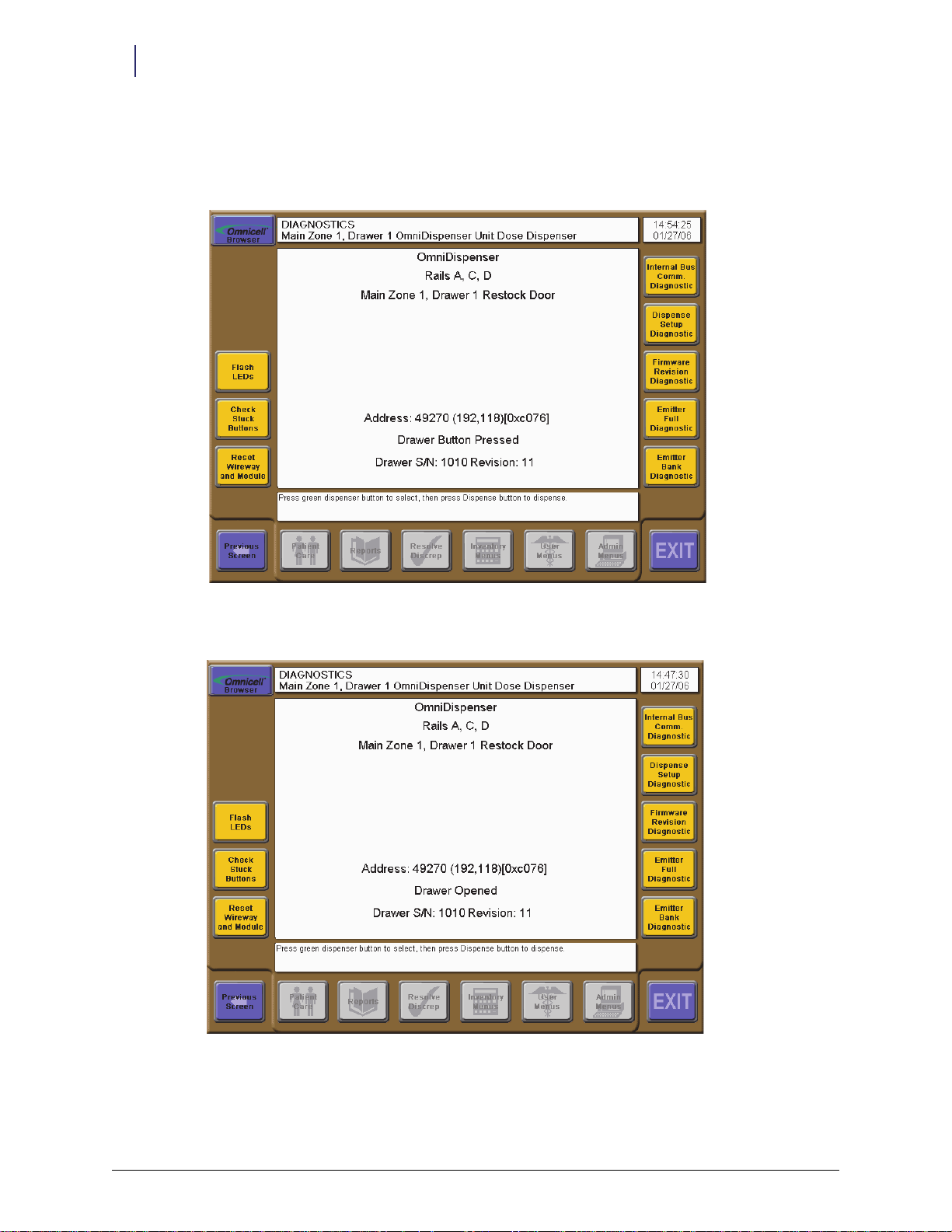
During the diagnostics function, the restock door behaves as follows:
When the user presses the restock door button, the restock door unlocks and the LED turns
on.
Figure 3-1. Restock door button pressed
When the user opens the restock door, the restock door LED flashes.
Figure 3-2. Restock door opened
OmniDispenser Technical Guide/60-3007 Rev G © 2012 Omnicell, Inc.
Page 23
Software Functional Overview 3-3
Color Touch Functionality
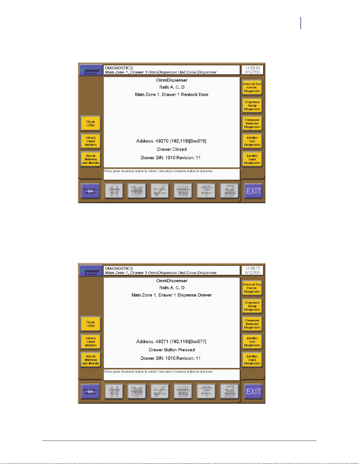
When the user closes the restock door, the restock door locks, and LED turns off.
Figure 3-3. Restock door closed
Dispenser Drawer Behavior
During the diagnostics function, the dispense drawer behaves as follows:
When the user presses the dispense drawer button, the dispense drawer unlocks and the LED
turns on.
Figure 3-4. Dispense drawer button pressed
© 2012 Omnicell, Inc. OmniDispenser Technical Guide/60-3007 Rev G
Page 24
3-4 Software Functional Overview
Color Touch Functionality
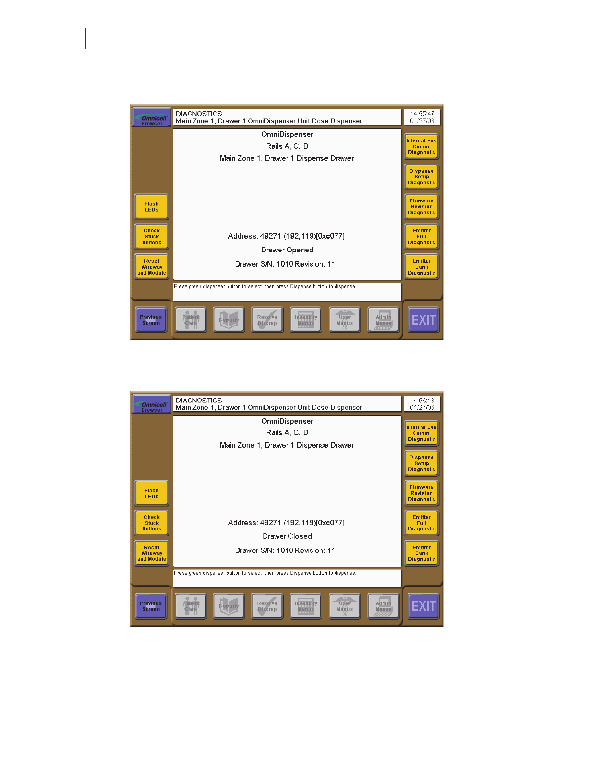
When the user opens the dispenser drawer, the dispense drawer LED flashes.
Figure 3-5. Dispense drawer opened
When the user closes the dispense drawer, the dispense drawer locks, and LED turns off.
Figure 3-6. Dispense drawer closed
Dispenser Behavior
During the diagnostics function, dispensers behave as follows:
When the user presses a dispenser button, the dispenser’s LED flashes.
OmniDispenser Technical Guide/60-3007 Rev G © 2012 Omnicell, Inc.
Page 25

Software Functional Overview 3-5
Color Touch Functionality
Dispense Function
The Dispense button displays on the Diagnostics window once the user has pressed a dispenser
button. The Dispense button remains available throughout the session, until the user opens the
dispense drawer or exits diagnostics.
Prior to pressing Dispense, the user should either position the rail frame so that selected dispenser
is over the trough in the restock door (recommended method) or push in the rail frame so that the
medication falls directly into the dispense drawer.
Pressing the Dispense button causes the dispenser to dispense one unit of medication. The results
of the dispense are displayed in the window and logged. These include status (
elapsed time, and any extended status from the firmware, if applicable.
OK /Retry / Fai l), the
Figure 3-7. Dispense Results
Dispense errors that occur while using the diagnostic function are not reported to the
Note:
OmniCenter.
If dispensing into the dispenser drawer, the user can press the Unlock Dispense Drawer button to
retrieve the medication, or select another function. If the user closes the restock door, the Unlock
Restock Door button also displays.
Any items dispensed must be placed back into the dispenser. There is no user interface for
replacing the items.
Empty Dispenser Function
The Empty Dispenser button displays on the Diagnostics window once the user has pressed a
dispenser button, as well as during various user functions where countback may be required. The
Empty Dispenser button remains available throughout the session, until the user opens the dispense
drawer or exits diagnostics.
© 2012 Omnicell, Inc. OmniDispenser Technical Guide/60-3007 Rev G
Page 26

3-6 Software Functional Overview
Color Touch Functionality
Prior to pressing Empty Dispenser, the user should either position the rail frame so that selected
dispenser is over the trough in the restock door (recommended method) or push in the rail frame
so that the medication falls directly into the dispense drawer.
Pressing the Empty Dispenser button causes the selected dispenser to dispense until empty or until
an error occurs. The number of units dispensed is displayed only during Diagnostics. (There is no
quantity display for other functions.) If the quantity dispensed is greater than zero (0), a null
transaction is sent to the OmniCenter (null type DD).
If emptying into the dispenser drawer, the user can press the Unlock Dispense Drawer button to
retrieve the medication, or select another function. If the user closes the restock door, the Unlock
Restock Door button also displays.
Any items dispensed must be placed back into the dispenser. There is no user interface for
replacing the items.
Figure 3-8. Empty Dispenser Results
Reset Wireway and Module Function
Pressing the Reset Wireway and Module button resets the wireway and reloads the rail configuration
for the selected OmniDispenser module.
Internal Bus Communications Diagnostics
Pressing the Internal Bus Comm Diagnostic button causes the firmware internal bus communication
diagnostic to run. This diagnostic also runs automatically, during midnight processing, and
whenever the module is initialized (during startup or when programming the module). The
possible results are:
Pass
Internal bus communication time-out
Internal bus communication corruption
OmniDispenser Technical Guide/60-3007 Rev G © 2012 Omnicell, Inc.
Page 27

Software Functional Overview 3-7
Color Touch Functionality
If the diagnostic fails, the board with the first failure is identified. Subsequent failures, if any, are
not identified.
Figure 3-9. Internal Bus Communications Diagnostics Results
Dispense Setup Diagnostics
Pressing the Dispense Setup Diagnostic button causes the firmware dispense setup diagnostic to run.
This diagnostic also runs automatically, during midnight processing, and whenever the module is
initialized (during startup or when programming the module). The possible results are:
Pass
Time- out dur ing stop unsolicited messages phase
Corrupted communication during stop unsolicited messages phase
Time-out while turning on emitters
Corrupted communication while turning on emitters
Time-out while turning on detector
Corrupted communication while turning on detector
Detector side A at max gain
Detector side B at max gain
Detector side A at minimum gain
Detector side B at minimum gain
Detector side A backoff beyond maximum gain
Detector side B backoff beyond maximum gain
Time-out during internal dispenser command
© 2012 Omnicell, Inc. OmniDispenser Technical Guide/60-3007 Rev G
Page 28

3-8 Software Functional Overview
Color Touch Functionality
If the diagnostic fails, the bank number with the first failure is identified. Subsequent failures, if
any, are not identified. The bank numbers are as follows:
Bank 0 = dispensers A1, B1, C1, D1, E1
Bank 1 = dispensers A2, B2, C2, D2, E2
Bank 2 = dispensers A3, B3, C3, D3, E3
Bank 3 = dispensers A4, B4, C4, D4, E4
Bank 4 = dispensers A5, B5, C5, D5, E5
Bank 5 = dispensers A6, B6, C6, D6, E6
Bank 6 = dispensers A7, B7, C7, D7, E7
Bank 7 = dispensers A8, B8, C8, D8, E8
Bank 8 = dispensers A9, B9, C9, D9, E9
Figure 3-10. Dispense Setup Diagnostics Results
Firmware Revision Diagnostics
Pressing the Firmware Revision Diagnostic button causes the firmware revision diagnostic to run. This
diagnostic also runs automatically, during midnight processing, and whenever the module is
initialized (during startup or when programming the module). The possible results are:
Pass
Internal Bus Communication time-out
Internal Bus Communication corruption
Board Firmware lower than sideboard
Board Firmware higher than sideboard
OmniDispenser Technical Guide/60-3007 Rev G © 2012 Omnicell, Inc.
Page 29

Software Functional Overview 3-9
Color Touch Functionality
If the diagnostic fails, the board with the first failure is identified. Subsequent failures, if any, are
not identified. In this event, the boards with the lowest firmware versions must be replaced or
upgraded to match the board with the highest firmware version.
Figure 3-11. Firmware Revision Diagnostics Results
Emitter Full Diagnostics
Pressing the Emitter Full Diagnostic button causes the firmware emitter diagnostic to run. This
diagnostic also runs automatically, during midnight processing. Due to the length of the test (1 to
5 minutes), a message box asks the user for confirmation to run the test. The possible results are:
Pass
Internal bus communication time-out
Internal bus communication corruption
Detector failed
Emitters failed
Detector stuck
If the diagnostic fails, the bank number with the first failure is identified. Subsequent failures, if
any, are not identified. The bank numbers are as follows:
Bank 0 = dispensers A1, B1, C1, D1, E1
Bank 1 = dispensers A2, B2, C2, D2, E2
Bank 2 = dispensers A3, B3, C3, D3, E3
Bank 3 = dispensers A4, B4, C4, D4, E4
Bank 4 = dispensers A5, B5, C5, D5, E5
Bank 5 = dispensers A6, B6, C6, D6, E6
Bank 6 = dispensers A7, B7, C7, D7, E7
Bank 7 = dispensers A8, B8, C8, D8, E8
© 2012 Omnicell, Inc. OmniDispenser Technical Guide/60-3007 Rev G
Page 30
3-10 Software Functional Overview
Color Touch Functionality
Bank 8 = dispensers A9, B9, C9, D9, E9
Figure 3-12. Emitter Full Diagnostics Results
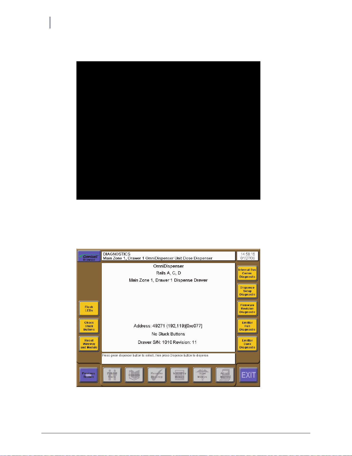
Check Stuck Buttons
If a drawer button is stuck, press Check Stuck Buttons for a diagnostic on the problem. The screen
will display the results.
Figure 3-13. Stuck Button DIagnostic
OmniDispenser Technical Guide/60-3007 Rev G © 2012 Omnicell, Inc.
Page 31

Software Functional Overview 3-11
Color Touch Functionality
Emitter Bank Diagnostics
Pressing the Emitter Bank Diagnostic button displays the emitter bank diagnostic window. The user
selects the banks to be tested, and once started, can cancel the test as needed, between banks. The
possible results are:
Pass
Internal bus communication time-out
Internal bus communication corruption
Detector failed
Emitters failed
Detector stuck
Figure 3-14. Emitter Bank Diagnostics Results
© 2012 Omnicell, Inc. OmniDispenser Technical Guide/60-3007 Rev G
Page 32

3-12 Software Functional Overview
Color Touch Functionality
Normal Restock
When a selected restock list contains OmniDispenser items, the applicable restock door and
dispenser LEDs flash. To select an item to restock, the user presses a flashing dispenser button.
Once pressed, the LED changes to steady on, and all other flashing LEDs are turned off. The user
presses the button once more when restock of the item is complete. Once complete, that dispenser
LED turns off, and the remaining LEDs resume flashing.
If a dispenser error occurs, the OmniCenter sets the restock record DISPERROR field to Y (Yes).
When the restock report is generated, the item appears on the report and is marked with an
asterisk (*). Additionally, the following message displays at the cabinet when the user restocks that
dispenser:
To perform a normal restock:
1. Log into the cabinet, then press Inventory Menus.
2. Press Normal Restock.
3. Select the desired restock from the list.
4. Press the flashing restock door button, then open the door.
5. Press a flashing dispenser button to select.
6. If the countback window is displayed, verify the current bin level as follows:
a. If needed, press Empty Dispenser to count the item. Refer to “Empty Dispenser Function” on
b. Press Ye s if the bin level displayed is correct.
This dispenser has reported errors, please check.
page 3-5 for details.
Figure 3-15. Normal Restock: Countback
OmniDispenser Technical Guide/60-3007 Rev G © 2012 Omnicell, Inc.
Page 33

Software Functional Overview 3-13
Color Touch Functionality
c. Press No if the bin level displayed is incorrect, then enter the actual countback amount.
Figure 3-16. Normal Restock: Restock Bin
7. Enter the restock quantity in the Actual Amount field.
8. Restock the item, then press the dispenser button again.
9. Repeat steps 5-8 until restock is complete, then close the restock door.
10. Press Exit to finish.
Supplemental Restock
To perform a supplemental restock of OmniDispenser items, the user first pre-selects the items.
When the user presses Restock Now, the restock door flashes and unlocks, and first applicable
dispenser LED flashes. The user presses the flashing dispenser button to restock that item. Once
pressed, the LED changes to steady on, and the LED of the next item, if any, flashes. The user can
then press the LED of the next item to restock or, if finished, close the restock door.
If any of the items in the OmniDispenser require a witness, witness information must be entered
before the restock door will unlock. Once entered, the witness applies to all witness-required items
for that restock.
To perform a supplemental restock:
1. Log into the cabinet, and press Inventory Menus.
2. Press Supplemental Restock.
3. Press the Restock Items button.
4. Select an item from the list.
5. Enter the Quantity to Restock.
6. Repeat steps 4-5 as needed, then press Restock Meds Now.
7. Enter witness, if required.
© 2012 Omnicell, Inc. OmniDispenser Technical Guide/60-3007 Rev G
Page 34

3-14 Software Functional Overview
Color Touch Functionality
8. Open the restock door.
9. Press the flashing dispenser button.
10. If the countback window displays, verify the current bin level as follows:
a. If needed, press Empty Dispenser to count the item.
b. Press Ye s if the bin level displayed is correct.
c. Press No if the bin level displayed is incorrect, then enter the actual countback amount.
11. Enter the restock quantity in the Actual Amount field.
12. Restock the item, then press the next flashing dispenser button.
13. Repeat steps 10-12 until restock is complete; close the restock door to finish.
Destock
Per usual functionality, the user must pre-select the items they want to destock from the
OmniDispenser. Items are then removed similarly to the Remove Meds function.
To p erf or m a d e st oc k :
1. Log into the cabinet, and press Inventory Menus.
2. Press Destock.
3. Press the Destock Items button.
4. Select an item from the list.
5. Enter the Quantity to Remove.
6. Repeat steps 4-5 as needed, then press Destock Meds Now.
7. Enter witness, if required.
8. Remove the items from the dispense drawer.
9. Press Destock Items to destock additional items, or press Exit to finish.
Cycle Count
To cycle count items in an OmniDispenser, the user selects the Cycle Count function from the
Inventory menu, then presses the restock door button to select that module. The user can then
navigate to the item via Find Item, or open the restock door and either press a dispenser button
directly or use the Find Dispenser Item function. The Empty Dispenser function can be used, as needed,
to obtain a count. Cycle count is then completed as usual.
To perform a cycle count:
1. Log into the cabinet, and press Inventory Menus.
2. Press Cycle Count.
3. Press the restock door button and open the restock door.
4. Press Find Dispenser Item to navigate to an item, or press a dispenser button.
Note:
When a multi-bin item is selected, the Next Bin button displays. This allows the user to perform
the current function across all applicable bins.
A Clear Dispenser Error button displays during the Cycle Coun t function. This allows users to manually clear a
dispense error without having to initiate a restock. The button displays/re-displays whenever a bin is
selected, regardless if an error has occurred for that bin.
OmniDispenser Technical Guide/60-3007 Rev G © 2012 Omnicell, Inc.
Page 35

5. Enter witness, if required.
6. Count the item, using the Empty Dispenser function as needed.
7. Enter the quantity counted, then press OK.
8. If desired, press Flash Uncounted Bins to flash all remaining bins in that module.
Note:
will continue to flash until they are counted or the user exits the function.
9. Repeat steps 4-8 as needed, then press Exit to finish.
Note: It is recommended that cycle counts be performed at regular intervals (once a week) instead of
relying on restock to discover/resolve discrepancies for slow moving medications.
Expiration/Recall
To perform an expiration or recall for OmniDispenser items, the user selects the Expired/Recalled
function from the Inventory menu, then presses the restock door button to select that module. The
user can then navigate to the item via Find Item, or open the restock door and either press a
dispenser button directly or use the Find Dispenser Item function. Expirations/recalls are then
completed as usual.
To perform an expiration or recall:
Software Functional Overview 3-15
Color Touch Functionality
Once Flash Uncounted Bins is pressed (during Cycle Count), all uncounted bins in the module
Modify Bin
1. Log into the cabinet, and press Inventory Menus.
2. Press Expired/Recalled.
3. Press the restock door button and open the restock door.
4. Press Find Dispenser Item to navigate to an item, or press a dispenser button.
Note: When a multi-bin item is selected, the Next Bin button displays. This allows the user to perform
the current function across all applicable bins.
5. Enter witness, if required.
6. Enter the Quantity to Expire or Recall, then press OK.
7. Repeat steps 4-6 as needed, then press Exit to finish.
To access the bin modification functions:
1. Log into the cabinet.
2. Press Inventory Menus.
3. Press Modify Bin.
Note: A Clear Dispenser Error button displays during the Modify Bin function. This allows users to manually
clear a dispense error without having to initiate a restock. The button displays/re-displays whenever a
bin is selected, regardless if an error has occurred for that bin.
© 2012 Omnicell, Inc. OmniDispenser Technical Guide/60-3007 Rev G
Page 36

3-16 Software Functional Overview
Color Touch Functionality
Select a Bin
There are two ways to select a dispenser:
Option 1:
1. Press the restock door button and open the door.
2. Press the button on the individual dispenser.
Option 2:
1. Press Find Item or open the restock door and press Find Dispenser Item.
Figure 3-17. Modify A Bin: Find Dispenser Item
OmniDispenser Technical Guide/60-3007 Rev G © 2012 Omnicell, Inc.
Page 37

2. Select the item from the list.
Software Functional Overview 3-17
Color Touch Functionality
Figure 3-18. Modify A Bin: Item List
3. If the item is in multiple locations, select the desired bin from the list.
Assigning an Item
To assign an item to an empty dispenser:
1. Press the restock door button and open the door.
2. Press the button on the dispenser.
3. Press the Assign Item button.
4. Proceed with bin assignment as usual.
Replacing an Item Assignment
There are two ways to replace an item in a dispenser:
Option 1:
1. Press the restock door button and open the door.
2. Press the button on the dispenser.
3. Press Assign Item.
4. Press Reassign Anyway or Assign Addition.
5. Proceed with bin assignment as usual.
Option 2:
1. Press Find Item or open the restock door and press Find Dispenser Item.
2. Select the desired item from the list.
3. If the item is in multiple bins, select the desired bin from the list.
© 2012 Omnicell, Inc. OmniDispenser Technical Guide/60-3007 Rev G
Page 38

3-18 Software Functional Overview
Color Touch Functionality
4. Press Replace Item.
5. Proceed with bin assignment as usual.
Deleting an Item Assignment
There are two ways to delete an item from a dispenser:
Option 1:
1. Press the restock door button and open the door.
2. Press the button on the dispenser.
3. Press Delete Item.
Option 2:
1. Press Find Item or open the restock door and press Find Dispenser Item.
2. Select the desired item from the list.
3. If the item is in multiple bins, select the desired bin from the list.
4. Press Delete Item.
Unassigning All Bins
To unassign/delete all items in the OmniDispenser:
1. Press the restock door button and open the door.
2. Press Unassign All Dispenser Items.
Setting Bin Level
There are two ways to modify the quantity of an item:
Option 1:
1. Press the restock door button and open the door.
2. Press the button on the dispenser.
3. Press Set Bin Level.
4. Proceed with bin level modification as usual.
Option 2:
1. Press Find Item or open the restock door and press Find Dispenser Item.
2. Select the desired item from the list.
3. If the item is in multiple bins, select the desired bin from the list.
4. Press Set Bin Level.
OmniDispenser Technical Guide/60-3007 Rev G © 2012 Omnicell, Inc.
Page 39

5. Proceed with bin level modification as usual.
Software Functional Overview 3-19
Color Touch Functionality
Figure 3-19. Modify A Bin: Modify Options
Countback Always Configuration
Countback is not required for OmniDispenser items because users only have access to the
medication dose(s) being dispensed. The Enable Countback Always for Unit Dose Compartment
configuration option is disabled by default.
Countback may be required for inventory purposes. If the facility does not want to countback
OmniDispenser items, Countback Always must be set to Disable and Countback Req must be set to
(no) for each dispenser item.
N
© 2012 Omnicell, Inc. OmniDispenser Technical Guide/60-3007 Rev G
Page 40

3-20 Software Functional Overview
OmniCenter Functionality
OmniCenter Functionality
User Access to Restock Door
In order to access the OmniDispenser restock door (or Sure-Med unit dose compartment), the
UD Access field must be enabled in the Users table for each applicable user. See “Implementation”
on page 4-1 for more details.
Reports
Pharmacy Drawer Configuration Report
The Pharmacy Drawer Configuration Report displays detailed drawer or bin location
information—particularly for OmniDispenser items.
Figure 3-20. Pharmacy Drawer Configuration Report
Dispensing Error Report
The Dispensing Error Report includes dispensing errors and bin location information for
OmniDispenser hardware. Accordingly, the report description displayed on the OmniCenter Reports
tab reads:
Figure 3-21. Dispensing Error Report
OmniDispenser Technical Guide/60-3007 Rev G © 2012 Omnicell, Inc.
Lists all unit dose dispenser errors for a specified date range and OmniSupplier.
Page 41

Message Alerts
Increase security by setting up an alert for forced entry detection (available in Omnicell v 14.2 or
higher). Attempted tampering with the OmniDispenser drawer is detected by a sensor that sets off
an alarm and displays a warning on the cabinet screen. A corresponding alert can be configured to
be e-mailed to designated recipients.
The alarm functions the same for any type of dispense drawer access.
Forced Entry Detection
Enable forced entry detection at the cabinet:
OmniConfigs > Pharmacy > Forced En try Detection =
Verify this setting before setting up a message alert.
Message Filter Setup
1. Log into the OmniCenter as the administrator.
2. Click on the Administrator tab.
3. Select
4. Select
Software Functional Overview 3-21
OmniCenter Functionality
Yes
Setup from the Type menu.
Message Filter Setup from the Options Available menu.
Figure 3-22. Administration Tab
5. Click Continue.
© 2012 Omnicell, Inc. OmniDispenser Technical Guide/60-3007 Rev G
Page 42

3-22 Software Functional Overview
OmniCenter Functionality
6. Create the tampering message.
a. Click the General sub-tab.
Figure 3-23. General Sub-Tab
b. Select Forced Entry to OmniDispenser from the Message Text list or click Add if message does not
already exist.
c. Check the Enabled box.
d. Set the priority level. (e.g. high)
e. Enter
Forced Entry to OmniDispenser in the Message Text field if not already populated from the
text message list.
f. Add a description if adding the message.
OmniDispenser Technical Guide/60-3007 Rev G © 2012 Omnicell, Inc.
Page 43
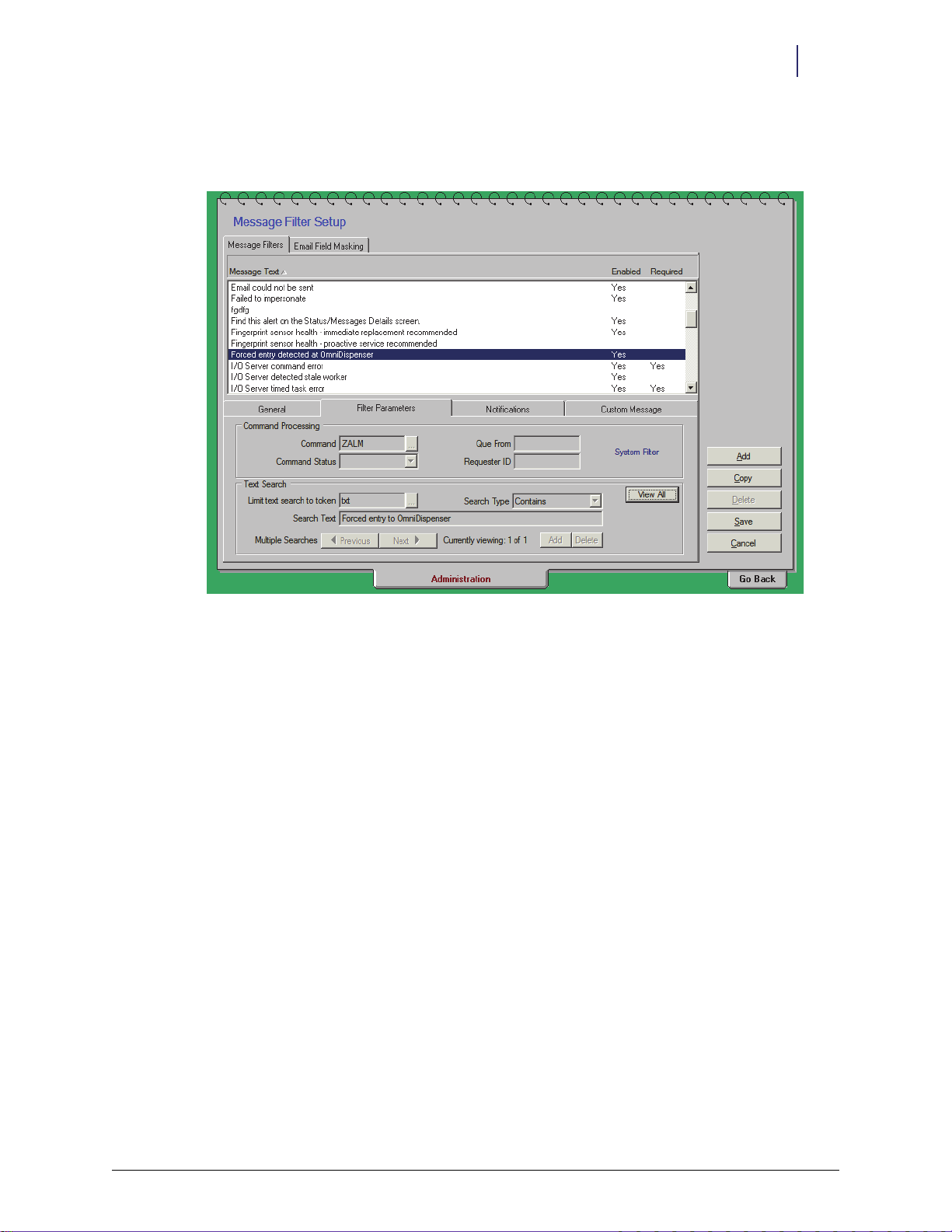
7. Select message parameters
a. Click the Filter Parameters sub-tab.
Software Functional Overview 3-23
OmniCenter Functionality
Figure 3-24. Parameters Sub-Tab
b. Type ZALM in the Command field.
c. Click Details.
d. Type
txt in the Limit Text Search To Token field.
e. Select Contains for the Search Type.
f. Enter
Forced Entry to OmniDispenser in the Search Text field.
© 2012 Omnicell, Inc. OmniDispenser Technical Guide/60-3007 Rev G
Page 44

3-24 Software Functional Overview
OmniCenter Functionality
8. Create recipient list.
a. Select the Notification sub-tab.
b. Click Add.
c. Select the desired recipients for the message alert from a user list and/or select a default
printer. Refer to the OmniCenter User guide for the Omnicell software version running on
the cabinet for details.
d. Click Add.
Figure 3-25. Add Window
OmniDispenser Technical Guide/60-3007 Rev G © 2012 Omnicell, Inc.
Page 45

Software Functional Overview 3-25
9. Enter an optional custom message on the Custom Message sub-tab.
OmniCenter Functionality
Figure 3-26. Custom Message Sub-Tab
10. Click Save.
11. Click Go Back to return to the original window.
© 2012 Omnicell, Inc. OmniDispenser Technical Guide/60-3007 Rev G
Page 46

3-26 Software Functional Overview
OmniCenter Functionality
OmniDispenser Technical Guide/60-3007 Rev G © 2012 Omnicell, Inc.
Page 47

Overview
4-1
Implementation
This chapter provides the general steps necessary to implement OmniDispenser module (ODM)
at an existing pharmacy or mixed-use account. For additional implementation information, see
the applicable technical manual or contact an Omnicell Project Manager.
The needs and existing setup of each facility will determine the actual implementation
requirements and order in which they are performed. Implementation requirements include:
Adjusting/installing rails, as needed
Installing, labeling, an loading the dispensers
Configuring the cabinet software
Assigning items
Enabling restock door access for the appropriate users
A Phillips #2 screw driver is required for implementing the hardware. Refer to “Field Service
Instructions” on page 5-1 for other required tools and kits.
Configuring Rails
Rails A, C, and D are fixed and always present. Optional rails B and E may require installation or
repositioning.
The required rail configuration should be determined during the pre-implementation process,
Note:
prior to ordering the OmniDispenser module and components.
Rails are removed and/or repositioned with the cabinet powered down. If reconfiguring an ODM
in an auxiliar y cabinet, both the main Color Touch and aux cabinet must be powered down. When
installation is complete and the cabinet (main and aux, if applicable) is powered on, the software
automatically detects the rail configuration.
© 2012 Omnicell, Inc. OmniDispenser Technical Guide/60-3007 Rev G
Page 48

4-2 Implementation
Rail Connector
Cover Pl ate
Configuring Rails
Install a Rail
1. Power down the main Color Touch cabinet. If reconfiguring an ODM in an auxiliary cabinet,
2. Remove the rear rail connector cover plate.
power down both the main and aux cabinet.
Figure 4-1. Removing the Rail Connector Cover Plate
3. Connect the rail back to the rear rail connector, then push the rail front down and into place.
Figure 4-2. Connecting Rail Back to Connector
4. Hand-tighten the front thumb-screw.
OmniDispenser Technical Guide/60-3007 Rev G © 2012 Omnicell, Inc.
Page 49

5. Complete any additional rail configurations, then power-up the cabinet. If reconfiguring an
Figure 4-3. Tightening the Mounting Screw
Remove a Rail
Implementation 4-3
Adjusting Dispensers
ODM in an auxiliary cabinet, power up both the main and aux cabinets.
1. Power down the main Color Touch cabinet. If reconfiguring an ODM in an auxiliary cabinet,
power down both the main and aux cabinet.
2. Remove any dispensers installed on the rail.
3. Loosen the front thumb-screw.
4. Pull the rail front up, away from the rail frame, then pull the rail back out of the rear connector.
5. Install the rear rail connector cover plate.
6. Complete any further rail configurations, then power-up the cabinet. If reconfiguring an ODM
in an auxiliary cabinet, power up both the main and aux cabinet.
Adjusting Dispensers
Caution: Failure to properly adjust the ATC/1ML/2ML slide can cause misdispenses. Carefully follow the
adjustment instructions provided in this section, based on the applicable cassette type.
1. Verify the type of cassette to be used in the ATC/1ML/2ML dispenser.
2. Check the setting at the base of the dispenser to see if it matches the cassette.
© 2012 Omnicell, Inc. OmniDispenser Technical Guide/60-3007 Rev G
Page 50

4-4 Implementation
Setting Window
Slide Screw
ATC
2ML
1ML
Setting Screw
(settings)
Adjusting Dispensers
3. If the setting does not match the cassette to be used, do the following steps:
Figure 4-4. Setting layout at base of dispenser
a. Use a Phillips screwdriver to remove the setting screw, then loosen the slide screw at the
base of the dispenser.
Figure 4-5. Removing the setting screw
b. Move the slide until the proper setting [ATC, 1ML, 2ML] can be seen through the window.
Figure 4-6. Moving the slide
OmniDispenser Technical Guide/60-3007 Rev G © 2012 Omnicell, Inc.
Page 51

Implementation 4-5
Installing Dispensers
c. Insert the setting screw, then tighten both screws.
Note:
The pictures below are only to demonstrate how a 1 ML and a 2 ML cassette fit into the adjustable
dispenser. Normally, dispensers are installed into the OmniDispenser, then the cassettes are loaded with meds
before they are put into the dispenser (as per the following sections).
Figure 4-7. Top view of 1 ML cassette in dispenser
Figure 4-8. Back view of 2 ML cassette in dispenser
Installing Dispensers
Important: Any portion of the implementation that involves handling of and/or access to controlled
medications must be overseen or performed by authorized pharmacy staff.
Note: The required dispenser configuration should be determined during the pre-implementation
process, prior to ordering the OmniDispenser module and components.
1. Locate the rail (A-E) and rail position (1-9) assigned to the dispenser.
2. Insert the dispenser into the desired connector on the rail, pressing firmly on top of the
dispenser to ensure a secure fit.
© 2012 Omnicell, Inc. OmniDispenser Technical Guide/60-3007 Rev G
Page 52

4-6 Implementation
Labeling Dispensers
3. Make sure the dispenser is securely connected and level before tightening the mounting screw.
4. Hand-tighten the mounting screw or use a #2 Phillips screw driver (provided in kit) to secure
Figure 4-9. Installing Dispensers
the dispenser.
Labeling Dispensers
There is no official process for labeling the individual dispensers and/or cassettes. It is
recommended that the labels have the generic name, trade name, and strength of each medication.
Use the OmniBin Label function in OmniCenter to print the labels. It can access the database with
the drug descriptions. Some sites may prefer white labels over the clear labels that come with the
cabinet. Suggested label types include Avery address labels for cassette dispensers and Avery file
folder labels for syringe dispensers.
Loading Dispensers
Oral Solids
Select a Cassette
Determine the correct cassette for a medication by referring to the facility’s Master Drug List.
Prior to implementation, a master drug list is typically developed by the facility, with the
assistance of the Omnicell Project Manager. The master drug list is based on the medications
traditionally used by the floors/stations with installed cabinets or is based on the master list for the
narcotics vault.
If the necessary information is not available in the Master Drug List, refer to “Appendix B:
Cassette Sizing Tool” on page B-1. The following subsection can also help with dispenser/cassette
selection.
Package Length and Width When the oral solid package is rectangular in shape, the longer
dimension is used as the package width and the shorter dimension is used as the package length.
The length and width of the medication package determines the insert type used in the cassette,
while the height determines the coil type.
OmniDispenser Technical Guide/60-3007 Rev G © 2012 Omnicell, Inc.
Page 53

Implementation 4-7
Loading Dispensers
The position, shape, and height of the blister (if present) is critical in determining which cassette
should be used in the dispenser to successfully dispense the drug package.
The following graphics, tables and examples illustrate the criteria used for the selection of a
cassette for an oral solid.
Selection Criteria
Insert Type Length & Width of medication package
Coil Type Height of medication package
Cassette Type Position, shape, size of blister
Table 4-1. Selection Criteria
Figure 4-10. Medication Packages
Insert Type Cassette #s Max. Width Max. Length
Small ribbed 3, 4, 7 1.10 0.66
Tylox ribbed 8, 12 1.17 0.80
Roxane ribbed 9, 11, 13 1.17 0.96
Large Flat 1, 2, 6, 10 1.52 0.86
U-Shape, Non-removable 5 1.52 1.28
Table 4-2. Cassette Insert Types
Cassette #s Height (in)
5 0.132
1, 3, 9, 12 0.148
6, 7 0.231
2, 4, 11 0.231
8, 10, 13 0.311
Table 4-3. Cassette Coil Type (height = distance between rings)
1. Determine the package dimensions (width, length, and height).
2. Use to identify those cassettes with an insert that can accommodate the package width and
length.
3. Use to identify those cassettes with a coil that can accommodate the package height.
4. Cross-reference the results of steps 2 and 3 to select a cassette type that meets both the insert
and coil requirements.
Example The following example uses a drug package measuring 1.35" W x 0.84" L x 0.28" H.
1. Based on Chart 1, cassettes 1, 2, 6, or 10 can accommodate the length and width.
© 2012 Omnicell, Inc. OmniDispenser Technical Guide/60-3007 Rev G
Page 54

4-8 Implementation
View from
bottom
Coil in 8:00
position
Meds inserted
bubble-up
Loading Dispensers
2. Based on Chart 2, cassettes 8, 10 and 13 have coils that can accommodate the package height.
3. Based on results from steps 1 and 2, cassette 10 is most appropriate for this medication.
Loading the Cassette
1. Cut the medication packaging into individual unit dose packages which are all the same size.
2. Open the cassette and lay it on its side.
3. For full loading:
4. For partial loading:
Trim the packages to avoid excess material around the edges.
a. Rotate the coil as needed to have a full loading space at the top, then load a package blister
side up (unless otherwise specified), oriented to the longest dimension.
b. Rotate the coil clockwise until the tip at the bottom is in the 8:00 position.
c. Continue loading from the bottom up between each set of coils so that they are oriented
with the longest dimension.
a. Rotate the coil so that the tip at the bottom is in the 8:00 position.
b. Load as needed from the bottom up between each set of coils so that they are oriented
blister side up to the longest dimension.
Figure 4-11. Orienting the Coil and Loading the Cassette
Loading is done from the bottom up because the weight of the med package will affect coil
Note:
spacing. Having the bottom coil tip at the 8:00 position secures the bottom dose while handling the
cassette.
5. Close the cassette door, checking to ensure that none of the packaging is dragging against the
door.
OmniDispenser Technical Guide/60-3007 Rev G © 2012 Omnicell, Inc.
Page 55

Syringes
Implementation 4-9
Loading Dispensers
6. Insert the cassette into the dispenser, ensuring the holding clamps at the top of the cassette are
latched.
Figure 4-12. Inserting the Cassette into the Dispenser
Note: OmniDispenser syringe dispensers are designed only for slim-pak syringes. Carpujects must be
in slim-pak containers prior to being loaded into the dispenser.
1. Align the syringe with the top opening and gently roll it into the dispenser, ensuring that it lies
flat.
Figure 4-13. Filling the Syringe Dispenser
Note: Syringe dispensers hold a quantity of 22 slim-pak syringes. Do not overfill.
Caution: Do not allow any syringes to stick out above the top of the dispenser.
2. Repeat step 1 until the dispenser is filled.
© 2012 Omnicell, Inc. OmniDispenser Technical Guide/60-3007 Rev G
Page 56

4-10 Implementation
Coil i n
6:00
position
Inserted
Vial
Loading Dispensers
Note: The syringe dispenser does not need to be removed from the OmniDispenser module to be
restocked.
Vials and Ampules
Selecting a Vial/Ampule Cassette or Dispenser
Dispenser /cassette selection for vials and ampules is dependent upon packaging:
Loading a Vial/Ampule Cassette
1. Remove the cassette from the dispenser, then open the cassette and lay it on its side.
2. Orient the coil so that the end is in the 6 o'clock position underneath the divider.
3. Starting from the bottom of the coil, load the first vial or ampule in the lowest opening
4. Repeat step three until the cassette is filled, then close the cassette door.
5. Insert the cassette into the dispenser, ensuring the holding clamps at the top of the cassette are
1 ml and 2 ml vials go into 1-2 ml cassettes; holds 18 vials
1 ml and 2 ml ampules go into 1-2 ml cassettes; holds 24 ampules
5 ml vials and ampules go directly into vial or ampule dispensers; holds 10 vials or ampules
between the side of the cassette and the insert. Load the next vial or ampule in the next
opening on the opposite side of the insert.
latched.
Figure 4-14. Loading a Vial/Ampule Cassette
OmniDispenser Technical Guide/60-3007 Rev G © 2012 Omnicell, Inc.
Page 57

Implementation 4-11
Configuring Cabinet Software
Loading a Vial/Ampule Dispenser
The #14-8033 dispenser kit contains the 5 ml vial dispenser (#15-8034) and a ruler-like loading
tool (#53-8156).
Figure 4-15. 5 ml vial dispenser and loading tool
1. Insert the loading tool flush down the side of the dispenser shaft.
Figure 4-16. 5 ml vial dispenser and loading tool
2. Align the (tall/skinny style) vials or ampules with the top facing the indented end of the shaft.
Figure 4-17. 5 ml vial dispenser and loading tool.
3. Gently roll up to 10 5ml vials into the dispenser, ensuring that it lies flat.
4. Remove the loading tool.
Configuring Cabinet Software
Programing the OmniDispenser’s Pharmacy Drawers
1. Log into the cabinet.
2. Press Omni Config.
3. Press Program Pharmacy Drawers.
4. Select the applicable cabinet and zone from the list.
© 2012 Omnicell, Inc. OmniDispenser Technical Guide/60-3007 Rev G
Page 58

4-12 Implementation
Configuring Cabinet Software
5. Follow the prompts to program each module/drawer in the selected zone. When prompted to
program an OmniDispenser module, press the dispense drawer button.
Figure 4-18. Programming the OmniDispenser
Cabinet Configuration Options
The following configuration options are directly applicable to OmniDispenser behavior. See the
latest Color Touch Configuration Options manual (DocuShare keyword: Config Options) or
applicable technical guide for additional configuration options.
Countback Always Configuration
Countback is not required for OmniDispenser items because users only have access to the
medication dose(s) being dispensed. Countback may be required for inventory purposes. The
Enable Countback Always for Unit Dose Compartment configuration option is set to disable by default. If
the facility does not want to require countback for OmniDispenser items, Countback Always must be
Disable, and Countback Req must be set to N (no) for each dispenser item.
set to
[PHARMACY]
Config Name: UDDCOUNTBACKALWAYS
Menu Name: Enable Countback Always for Unit Dose Compartment
Description Enables or disables the Countback Always feature for Unit Dose
Values Enabled; Disabled
Default Disabled
Compartments. This option affects all OmniDispensers and Sure-Med
Unit Dose compartments
OmniDispenser Technical Guide/60-3007 Rev G © 2012 Omnicell, Inc.
Page 59

Implementation 4-13
Configuring Cabinet Software
The Countback and Cycle Count Show Current Quantity configuration option setting will be
Note:
ignored by OmniDispenser and Sure-Med Unit Dose modules. Both countback and cycle count always
show current quantity for unit dose modules.
FIFO Configuration
The Always Use FIFO for Multiple Bins configuration option affects dispensing behavior for
OmniDispenser and Sure-Med unit dose modules. This option affects the dispense order for
multi-bin items assigned across one or more unit-dose dispensers and/or other pharmacy bins
(non-unit-dose).
If enabled, the software issues the item from the same bin until empty, then moves on to the next
bin and so on. If disabled, the software issues from all dispenser locations first, before dispensing
from any drawer/non-dispenser locations. In this case, issues revert back to the dispenser(s)
immediately upon restock, regardless of the bin level of the currently indicated bin.
[PHARMACY]
Config Name: FIFOALWAYS
Menu Name: Always use FIFO for multiple bins or remove from unit dose
dispensers first.
Description Uses FIFO or empties unit dose first for items in mixed UDD and non-
UDD bins.
Valu es Yes; No
Default No
Time-out Configuration
Dispense Drawer Time-out The Transac tion Middle Time-out configuration setting determines the
amount of time the user has to open dispense drawer during a transaction. If the user does not
open the dispense drawer within the set amount of time, a warning sounds and the user is logged
out. If any items were dispensed during the transaction, a null transaction is sent to the
OmniCenter (null type DN: Dispense Drawer Not Opened).
This behavior does not apply during diagnostics functions.
[MISC]
Config Name: Transaction Middle Time-out
Menu Name: Transaction Middle Time-out (in seconds)
Description The time-out limit for the remainder of a user function (such as
transaction, restock, cycle count, etc.) goes into effect after the first key
or button press. For OmniDispenser, this setting determines the amount
of time the user has to open the dispense drawer during a transaction.
Values 0 to 86400 seconds
Default 45 seconds
Note:
A zero (0) value denotes no time-out. Having no time-out is not recommended.
© 2012 Omnicell, Inc. OmniDispenser Technical Guide/60-3007 Rev G
Page 60

4-14 Implementation
Assigning Items
Restock Drawer Time-out The Inventory Time-out configuration setting determines the amount of
time the user has to open restock door during an inventory function. If the user does not open the
restock door within the set amount of time, a warning sounds and the user is logged out.
[MISC]
Note:
Config Name: Inventory Time-Out
Menu Name: Inventory Time-Out (in seconds)
Description Sets time-out (in seconds) for Inventory functions. For OmniDispenser,
this setting determines the amount of time the user has to open the
restock door during a transaction.
Values 0 to 86400 seconds
Default 600 Seconds
A zero (0) value denotes no time-out. Having no time-out is not recommended.
Assigning Items
This section assumes that items are being assigned to unassigned dispensers. If re-using
dispensers previously assigned, refer to “Modify Bin” on page 3-15 for the Reassign and Assign
Additional functions.
Item assignment is performed at the cabinet level, per usual functionality. This guide assumes that
the OmniCenter Items database is up-to-date and contains the items to be assigned to the
OmniDispenser module.
OmniDispenser items can be assigned once the module has been programmed (see above), the
items have been sent from the OmniCenter to the cabinet, and the dispensers are installed on the
rails.
To assign an item to an empty dispenser:
1. Log into the cabinet, then press Inventory Menus.
2. Press Modify Bin.
3. Press the restock door button and open the door.
4. Press the button on the dispenser.
5. Press the Assign Item button.
OmniDispenser Technical Guide/60-3007 Rev G © 2012 Omnicell, Inc.
Page 61

6. Proceed with bin assignment as usual.
Implementation 4-15
Enabling User Access to Restock Door
Figure 4-19. Assign Item window
Enabling User Access to Restock Door
At the OmniCenter, the facility can enable or disable individual user access to the OmniDispenser
restock door. Once enabled, the user can access the restock door for all associated OmniDispenser
modules and Sure-Med Unit Dose compartments.
For Inventory and Patient Care Functions, the user must be UD Access/Pharmacy-enabled and
have the correct control level access for all items contained in the OmniDispenser module. If the
user does not have access to any item contained in the module, the restock door will not open,
and a message displays.
For Inventory Menus functions, any UD Access/Pharmacy-enabled user can access the restock
compartment. However, the software only allows the user to select items / dispensers for which
they have proper control level access.
To enable/disable restock door access for a user:
1. Log into the OmniCenter.
2. Click on the Database tab, then select the Users table.
3. Select the applicable user record, then click Modify.
4. Click the OmniSupplier radio button.
5. Select the UD Access field to enable access (or) deselect the field to disable access.
Note: The UD Access field appears grayed-out and can not be modified if the logged in user does not
have the appropriate access privileges.
In order to alter the UD Access field for another user, the logged-in user must have server access level of
7, 8, 9 or C, and be a UD Access-enabled user.
© 2012 Omnicell, Inc. OmniDispenser Technical Guide/60-3007 Rev G
Page 62

4-16 Implementation
Enabling User Access to Restock Door
6. Verify that the Pharmacy field is selected, and that the user has the correct control level access
(DEA Schedule # fields) for all medications that are contained in the OmniDispenser.
7. Click Save.
Figure 4-20. Enabling Restock Door Access
OmniDispenser Technical Guide/60-3007 Rev G © 2012 Omnicell, Inc.
Page 63

Overview
Field Service Instructions
This chapter provides service procedure instructions that can be performed at the customer
facility by a qualified Omnicell representative. To determine which, if any, service procedure is
necessary, refer to “Appendix C: Troubleshooting Guide” on page C-1.
The following OmniDispenser module (ODM) components can be replaced in the field:
Rail assembly (rail frame)
Rails B through E (rail dividers: fixed or optional)
Restock door
Dispense drawer and dispense drawer cable
Top c ro ss ba r
Rail cable
Carrier controller board
5-1
A list of field-replaceable parts, with ordering descriptions and part numbers, is provided at the
end of this chapter.
Figure 5-1. Required Parts
© 2012 Omnicell, Inc. OmniDispenser Technical Guide/60-3007 Rev G
Page 64

5-2 Field Service Instructions
Replacing the Rail Assembly
Tools Required
One or more of the following tools are required to perform each service function in this chapter:
T8 Torx Driver
T10 Torx Driver
T15 Torx Driver
Two 3/18" open-ended C-wrenches
Note: Rails are removed, installed and/or repositioned with the cabinet powered down. If servicing or
reconfiguring an ODM in an auxiliary cabinet, both the main Color Touch and aux cabinet must be
powered down. When installation is complete and the cabinet (main and aux, if applicable) is powered
on, the software automatically detects the rail configuration.
Important: Any service procedure that grants access to controlled medications must be supervised by
authorized pharmacy staff.
Replacing the Rail Assembly
The rail assembly consists of the rail frame (front, back and sides) and fixed rails A, C and D. If a
problem occurs with a component of the rail assembly, and can not be resolved by swapping out a
rail (B through E)3 or rail cable, the entire assembly is replaced (PN#14-8017).
Fixed rails C and D, and optional rails B and E can be replaced. If a problem occurs with rail A or
other portion of the rail frame, the entire rail assembly must be replaced. In this event, any
optional rails are removed and installed in the new rail assembly.
Access the OmniDispenser
1. Perform a graceful shutdown of the CT console, then power down the cabinet. If servicing an
ODM in an auxiliary cabinet, power down both cabinets (main and aux).
2. Unlock and remove the manual override cover.
3. Pull the manual override lever and open the restock door.
4. Pull the rail frame out until fully extended.
Figure 5-2. Extending the rail frame
OmniDispenser Technical Guide/60-3007 Rev G © 2012 Omnicell, Inc.
Page 65

Remove the Rail Assembly
1. Use a T-10 Torx driver to remove two 6-32 flat-head screws securing the rail cable bracket
Figure 5-3. Removing the rail cable bracket (6-32 flat-head screws)
2. Use a T-10 Torx driver to loosen the 6-32 button-head screw securing the rail cable bracket to
the rail frame.
3. Remove the rail cable bracket and set aside.
Field Service Instructions 5-3
Replacing the Rail Assembly
Figure 5-4. Removing the rail cable bracket (6-32 button-head screws)
© 2012 Omnicell, Inc. OmniDispenser Technical Guide/60-3007 Rev G
Page 66

5-4 Field Service Instructions
Replacing the Rail Assembly
4. Disconnect the rail cable from P1 on the rail controller board.
Figure 5-5. Disconnecting the rail cable
5. Simultaneously push down on the right and left drawer slide release levers.
6. Hold the release levers down and pull the rail assembly out and set aside.
Figure 5-6. Removing the rail assembly
OmniDispenser Technical Guide/60-3007 Rev G © 2012 Omnicell, Inc.
Page 67

Install the New Rail Assembly
1. Align the new rail assembly with the drawer slides.
Figure 5-7. Inserting the rail assembly
2. Insert the rail assembly into the drawer slides until fully engaged
3. Connect the rail cable to P1 on the rail controller board.
Field Service Instructions 5-5
Replacing the Rail Assembly
Figure 5-8. Connecting the rail cable
4. Reinstall the rail cable bracket.
a. Use a T-10 Torx driver to tighten the 6-32 button head screw that secures the rail cable
bracket to the rail frame
b. Use a T-10 Torx driver to install two 6-32 flat-head screws that secures the rail cable
bracket.
© 2012 Omnicell, Inc. OmniDispenser Technical Guide/60-3007 Rev G
Page 68

5-6 Field Service Instructions
Replacing/Adding/Removing Rails
Replacing/Adding/Removing Rails
Fixed rails C and D can be replaced, but must be present for proper operation. Optional rails B
and E can be added, replaced or removed as needed. If a problem exists with fixed rail A, the
entire rail assembly must be replaced. See “Replacing the Rail Assembly” on page 5-2.
Rails are removed, installed and/or repositioned with the cabinet powered down. If servicing or
reconfiguring an ODM in an auxiliary cabinet, both the main Color Touch and aux cabinet must
be powered down. When installation is complete and the cabinet (main and aux, if applicable) is
powered on, the software automatically detects the rail configuration.
Access the OmniDispenser
1. Perform a graceful shutdown of the CT console, then power down the cabinet. If servicing an
ODM in an auxiliary cabinet, power down both cabinets (main and aux).
2. Unlock and remove the manual override cover.
3. Pull the manual override lever and open the restock door.
4. Pull the rail frame out until fully extended.
Figure 5-9. Extending the rail frame
OmniDispenser Technical Guide/60-3007 Rev G © 2012 Omnicell, Inc.
Page 69

Remove Rails (B-E)
Fixed Rail Mount
Optional Rail
Mount
1. Fixed rail: Use a T-15 Torx driver to remove the 8-32 button-head screw securing the fixed rail
to the rail frame.
Optional rail: Loosen the thumb-screw.
Field Service Instructions 5-7
Replacing/Adding/Removing Rails
Figure 5-10. Removing a fixed or optional rail
2. Gently lift the rail front, then pull the rail free from the rear rail connector.
Figure 5-11. Removing a fixed rail
Note: To permanently remove the optional rails, use a T-8 Torx driver to secure the rail connector cover
over the empty slot with a 4-40 flat-head screw.
© 2012 Omnicell, Inc. OmniDispenser Technical Guide/60-3007 Rev G
Page 70

5-8 Field Service Instructions
Fixed Rail Mount
Optional Rail
Mount
Replacing/Adding/Removing Rails
Replace Rails (B-E)
1. Insert the new rail.
2. Connect the rail back to the rear rail connector.
3. Push the rail front down and into place.
Figure 5-12. Connecting rail back to connector
4. Fixed rail: Use the T-15 Torx driver to install the 8-32 button-head screw to secure the fixed
rail to the rail frame.
Optional rail: Hand-tighten the thumb-screw.
Figure 5-13. Tightening the mounting screws
5. Complete any additional rail configurations, then power-up the cabinet. If reconfiguring an
ODM in an auxiliary cabinet, power-up both the main and aux cabinets.
OmniDispenser Technical Guide/60-3007 Rev G © 2012 Omnicell, Inc.
Page 71

Add Optional Rails (B and E)
Rail Connector
Cover Plate
Optional rails can be installed into unused rail slots.
1. Perform a graceful shutdown of the CT console, then power down the cabinet. If servicing an
ODM in an auxiliary cabinet, power down both cabinets (main and aux).
2. Unlock and remove the manual override cover.
3. Pull the manual override lever and open the restock door.
4. Pull the rail frame out until fully extended.
Field Service Instructions 5-9
Replacing/Adding/Removing Rails
Figure 5-14. Extending the rail frame
5. Use the T8 Torx driver to remove the 4-40 flat-head screw securing the rail connector cover
plate. Save the cover plate and screw for later reconfiguration.
Figure 5-15. Removing the rail connector cover plate
6. Refer to “Replace Rails (B-E)” on page 5-8 for installing the optional rails.
© 2012 Omnicell, Inc. OmniDispenser Technical Guide/60-3007 Rev G
Page 72

5-10 Field Service Instructions
trunnion bar
Replacing the Restock Door
Replacing the Restock Door
If a problem occurs with a component of the restock door, such as the hinges, braces (trunnion
bars) or latch, the entire door assembly is replaced (PN#15-8019).
Access the OmniDispenser
1. Perform a graceful shutdown of the CT console, then power down the cabinet. If servicing an
ODM in an auxiliary cabinet, power down both cabinets (main and aux).
2. Unlock and remove the manual override cover.
3. Pull the manual override lever and open the restock door.
4. Pull the rail frame out until fully extended.
Figure 5-16. Extending the rail frame
Remove the Restock Door
1. Remove the rail assembly. Refer to “Remove the Rail Assembly” on page 5-3.
2. Use a T-10 Torx driver to remove two 6-32 flat-head screws securing the trunnion bars (one
screw per bar) to the module interior.
Figure 5-17. Detaching the trunnion bars
OmniDispenser Technical Guide/60-3007 Rev G © 2012 Omnicell, Inc.
Page 73

Field Service Instructions 5-11
Replacing the Restock Door
3. Use a T-10 Torx driver to remove three 6-32 flat-head screws securing the fix inhibitor bracket.
Figure 5-18. Removing the fix inhibitor bracket
4. Remove the fix inhibitor bracket and set aside.
5. Use a T-15 Torx driver to remove six 8-32 flat-head screws securing the door hinges to the
bottom crossbar (three screws per hinge).
Figure 5-19. Detaching the door hinges
6. Carefully remove the restock door, taking care not to bend the trunnion bars.
© 2012 Omnicell, Inc. OmniDispenser Technical Guide/60-3007 Rev G
Page 74

5-12 Field Service Instructions
trunnion
bar
Replacing the Restock Door
Install the New Restock Door
1. Position the new restock door—aligning the two door hinges with the holes in the bottom
crossbar.
2. Use a T-15 Torx driver to install six 8-32 flat-head screws to secure the door hinges to the
bottom crossbar (three screws per hinge).
Figure 5-20. Attaching the door hinges
3. Use a T-10 Torx driver to install two 6-32 flat-head screws to secure the trunnion bars to the
module interior (one screw per trunnion bar).
Figure 5-21. Attaching the trunnion bars
4. Align the fix inhibitor bracket over the bottom crossbar.
OmniDispenser Technical Guide/60-3007 Rev G © 2012 Omnicell, Inc.
Page 75

Field Service Instructions 5-13
Replacing the Dispense Drawer
5. Use a T-10 Torx driver to install three 6-32 flat-head screws to secure the fix inhibitor bracket.
Figure 5-22. Installing the fix inhibitor bracket
6. Install the rail assembly. Refer to “Install the New Rail Assembly” on page 5-5.
Replacing the Dispense Drawer
If a problem occurs with a component of the dispense drawer that cannot be resolved by replacing
the drawer cable (such as bad LED or latch), the entire drawer is replaced (PN#14-8025).
Access the OmniDispenser
1. Perform a graceful shutdown of the CT console, then power down the cabinet. If servicing an
ODM in an auxiliary cabinet, power down both cabinets (main and aux).
2. Unlock and remove the manual override cover.
3. Pull the manual override lever and open the restock door.
4. Pull the rail frame out until fully extended.
Figure 5-23. Extending the rail frame
© 2012 Omnicell, Inc. OmniDispenser Technical Guide/60-3007 Rev G
Page 76

5-14 Field Service Instructions
Replacing the Dispense Drawer
Remove the Dispense Drawer
1. Remove the rail assembly. Refer to “Remove the Rail Assembly” on page 5-3.
2. Remove the restock door. Refer to “Remove the Restock Door” on page 5-10.
Figure 5-24. Removing the restock door
3. Pull the drawer manual override, and open the drawer until fully extended.
4. Use a T-10 Torx driver to remove two 6-32 flat-head screws securing the cable bracket to the
drawer.
Figure 5-25. Removing the drawer cable bracket
5. Remove the cable bracket and set aside.
OmniDispenser Technical Guide/60-3007 Rev G © 2012 Omnicell, Inc.
Page 77

Field Service Instructions 5-15
Replacing the Dispense Drawer
6. Disconnect the drawer cable from J1 on the drawer controller board.
Figure 5-26. Disconnecting the drawer cable
7. Simultaneously push down on the right and left drawer slide release levers.
8. Hold the release levers down and pull the dispense drawer out, then set it aside.
Figure 5-27. Removing the dispense drawer
© 2012 Omnicell, Inc. OmniDispenser Technical Guide/60-3007 Rev G
Page 78

5-16 Field Service Instructions
Replacing the Dispense Drawer
Install the New Dispense Drawer
1. Align the new dispense drawer with the drawer slides.
Figure 5-28. Installing the dispense drawer
2. Insert the dispense drawer into the drawer slides until fully engaged.
3. Connect the drawer cable to J1 on the drawer controller board.
Figure 5-29. Connecting the drawer cable
OmniDispenser Technical Guide/60-3007 Rev G © 2012 Omnicell, Inc.
Page 79

Field Service Instructions 5-17
Replacing the Dispense Drawer Cable
4. Use a T-10 Torx driver to install two 6-32 flat-head screws to secure the cable bracket to the
drawer.
Figure 5-30. Installing the drawer cable bracket
5. Install the restock door. Refer to “Install the New Restock Door” on page 5-12.
6. Install the rail assembly. Refer to “Install the New Rail Assembly” on page 5-5.
Replacing the Dispense Drawer Cable
The dispense drawer cable connects the dispense drawer controller to the carrier controller. The
cable can be replaced as needed (PN#42-8039).
Note: The dispense drawer cable (PN#42-8039) is unique, and cannot be substituted with a pharmacy
II drawer cable or OmniDispenser rail cable.
Access the OmniDispenser
1. Perform a graceful shutdown of the CT console, then power down the cabinet. If servicing an
ODM in an auxiliary cabinet, power down both cabinets (main and aux).
2. Unlock and remove the manual override cover.
3. Pull the manual override lever and open the restock door.
© 2012 Omnicell, Inc. OmniDispenser Technical Guide/60-3007 Rev G
Page 80

5-18 Field Service Instructions
Replacing the Dispense Drawer Cable
4. Pull the rail frame out until fully extended.
Figure 5-31. Extending the rail frame
Remove the Drawer Cable
1. Remove the rail assembly. Refer to “Remove the Rail Assembly” on page 5-3.
2. Remove the restock door. Refer to “Remove the Restock Door” on page 5-10.
Figure 5-32. Removing the restock door
OmniDispenser Technical Guide/60-3007 Rev G © 2012 Omnicell, Inc.
Page 81

Field Service Instructions 5-19
Replacing the Dispense Drawer Cable
3. Remove the dispense drawer. Refer to “Remove the Dispense Drawer” on page 5-14 (steps 3-
8).
Figure 5-33. Removing the dispense drawer
4. Use a T-15 Torx driver to remove four 8-32 flat-head screws securing the bottom crossbar (two
screws on each side).
The two flat-head screws on the right (8-32 x 3/8) are longer than the two on the left (8-32 x 1/4).
Note:
Figure 5-34. Removing the bottom crossbar
5. Remove the bottom crossbar and set aside.
© 2012 Omnicell, Inc. OmniDispenser Technical Guide/60-3007 Rev G
Page 82

5-20 Field Service Instructions
Replacing the Dispense Drawer Cable
6. Use a T-8 Torx driver to remove four 4-40 flat-head screws securing carrier controller cover.
Figure 5-35. Removing the carrier controller cover
7. Remove the carrier controller cover and set aside.
8. Use a T-15 Torx driver to remove two 8-32 button-head screws securing the middle bayonet.
Figure 5-36. Removing the middle bayonet
9. Pull the bayonet away from the frame—just enough to access the rail cable routed behind it.
OmniDispenser Technical Guide/60-3007 Rev G © 2012 Omnicell, Inc.
Page 83

Field Service Instructions 5-21
P1
Replacing the Dispense Drawer Cable
10. Unplug the rail cable from P1 on the carrier controller board.
Figure 5-37. Disconnecting the rail cable
11. Set the middle bayonet and its rail cable aside.
12. Use a T-15 Torx driver to remove two 8-32 button-head screws securing the bottom bayonet.
Figure 5-38. Removing the bottom bayonet
13. Remove the bottom bayonet and set aside.
© 2012 Omnicell, Inc. OmniDispenser Technical Guide/60-3007 Rev G
Page 84

5-22 Field Service Instructions
P2
Replacing the Dispense Drawer Cable
14. Use a T-15 Torx driver to remove two 8-32 button-head screws securing the drawer bayonet.
The second screw (in area circled) is not visible in Figure 5-39.
Figure 5-39. Removing the drawer bayonet
15. Disconnect the dispense drawer cable from P2 on the carrier controller board.
Figure 5-40. Disconnecting the dispense drawer cable
16. Remove the dispense drawer cable from the drawer bayonet and discard the cable.
Install the New Drawer Cable
1. Place the dispense drawer cable into the drawer bayonet.
OmniDispenser Technical Guide/60-3007 Rev G © 2012 Omnicell, Inc.
Page 85

Field Service Instructions 5-23
P2
Replacing the Dispense Drawer Cable
2. Slide the plastic tab on the cable between the spring and outer wall of the bayonet.
Figure 5-41. Inserting the new dispense drawer cable into the drawer bayonet
3. Connect the dispense drawer cable to P2 on the carrier controller board.
Figure 5-42. Connecting the dispense drawer cable to the carrier controller
4. Use a T-15 Torx driver to install two 8-32 button-head screws secure the drawer bayonet. The
second screw (in circled area) is not visible in Figure 5-43.
© 2012 Omnicell, Inc. OmniDispenser Technical Guide/60-3007 Rev G
Page 86

5-24 Field Service Instructions
Replacing the Dispense Drawer Cable
5. Make sure the free cable end which will be plugged into the drawer is positioned above drawer
bayonet.
Figure 5-43. Installing the drawer bayonet
6. Use a T-15 Torx driver to install two 8-32 button-head screws to secure the bottom bayonet.
7. Make sure the drawer cable is behind the bayonet and is not pinched.
Figure 5-44. Installing the bottom bayonet
OmniDispenser Technical Guide/60-3007 Rev G © 2012 Omnicell, Inc.
Page 87

Field Service Instructions 5-25
P1
Replacing the Dispense Drawer Cable
8. Hold the middle bayonet and connect the rail cable to P1 on the carrier controller board.
Figure 5-45. Connect the rail cable
9. Use a T-8 Torx driver to install two 8-32 button-head screws to secure the middle bayonet.
10. Make sure the free cable end which will be plugged into the rail frame is positioned above the
drawer bayonet.
11. Tuck excess cable behind the bayonets.
Figure 5-46. Installing the middle bayonet
© 2012 Omnicell, Inc. OmniDispenser Technical Guide/60-3007 Rev G
Page 88

5-26 Field Service Instructions
Replacing the Dispense Drawer Cable
12. Use a T-15 Torx driver to install four 4-40 flat-head screws securing carrier controller cover.
Figure 5-47. Installing the carrier controller cover
13. Use a T-15 Torx driver to install four 8-32 flat-head screws securing the bottom crossbar (two
screws on each side). Use the two longer screws on the right side.
Note: The two flat-head screws used on the right side (8-32 x 3/8) are longer than the two used on the
left side (8-32 x 1/4).
Figure 5-48. Installing the bottom crossbar
OmniDispenser Technical Guide/60-3007 Rev G © 2012 Omnicell, Inc.
Page 89

Install the Dispense Drawer
1. Align the new dispense drawer with the drawer slides.
Figure 5-49. Installing the dispense drawer
2. Insert the dispense drawer into the drawer slides until fully engaged.
3. Connect the drawer cable to J1 on the drawer controller board.
Field Service Instructions 5-27
Replacing the Dispense Drawer Cable
Figure 5-50. Connecting the drawer cable
© 2012 Omnicell, Inc. OmniDispenser Technical Guide/60-3007 Rev G
Page 90

5-28 Field Service Instructions
Replacing the Top Crossbar
4. Use a T-10 Torx driver to install two 6-32 flat-head screws to secure the cable bracket to the
drawer.
Figure 5-51. Installing the drawer cable bracket
5. Install the restock door. Refer to “Install the New Restock Door” on page 5-12.
6. Install the rail assembly. Refer to “Install the New Rail Assembly” on page 5-5.
Replacing the Top Crossbar
If a door release cable (manual override) needs to be adjusted, refer to “Install the New Cross Bar”
on page 5-32(steps 7-9).
If a problem occurs with a component of the top crossbar (such as bad LED or latch), the entire
crossbar is replaced (PN#14-8025).
Note: The instructions in this section assume that the entire crossbar is being replaced. In some cases,
it may be more efficient to order a new top crossbar, and use parts from it to repair the existing top
crossbar. This is at the discretion of the Omnicell representative.
Access the OmniDispenser
1. Perform a graceful shutdown of the CT console, then power down the cabinet. If servicing an
ODM in an auxiliary cabinet, power down both cabinets (main and aux).
2. Unlock and remove the manual override cover.
3. Pull the manual override lever and open the restock door.
Remove the Top Cross Bar
1. Use a T-15 Torx driver to remove two 8-32 flat-head screws securing the right side of the top
crossbar to the carrier.
OmniDispenser Technical Guide/60-3007 Rev G © 2012 Omnicell, Inc.
Page 91

Field Service Instructions 5-29
Replacing the Top Crossbar
Note:
The picture in Figure 5-52 shows the carrier controller cover already removed. The cover should
be on during normal operation.
Figure 5-52. Removing the top crossbar: two 8-32 flat-head screws
2. Use a T-15 Torx driver to remove two 8-32 flat-head screws securing the left side of the top
crossbar to the carrier.
Figure 5-53. Removing the top crossbar: two 8-32 flat-head screws
3. Remove the top crossbar by sliding forward, until free from the carrier.
Note: If the crossbar is difficult to remove, try tapping the back with a rubber mallet.
4. Disconnect the 14-pin ribbon cable from TB1 on the transition board.
© 2012 Omnicell, Inc. OmniDispenser Technical Guide/60-3007 Rev G
Page 92

5-30 Field Service Instructions
Cable Sl ot
Replacing the Top Crossbar
5. Remove the ribbon cable by feeding backward through the cable slot in the top crossbar.
Figure 5-54. Disconnecting the ribbon cable
6. Use a T-15 Torx driver to remove the 8-32 flat-head screw securing the door release cable to
the top crossbar.
7. Remove the door spring and set it aside.
Figure 5-55. Removing the door release cable
OmniDispenser Technical Guide/60-3007 Rev G © 2012 Omnicell, Inc.
Page 93

Field Service Instructions 5-31
Door
Release
Bracket
Replacing the Top Crossbar
8. Use a T-10 Torx driver to remove the center 6-32 flat-head screw securing the latch cover
bracket.
Figure 5-56. Loosening the latch cover bracket
9. Rotate the latch cover bracket clockwise to access the door release bracket.
10. Use a T-10 Torx driver to remove the 6-32 truss-head screw securing the door release bracket.
Figure 5-57. Removing the door release bracket: 6-32 truss head screw
11. Lift the door release bracket away from the top crossbar.
© 2012 Omnicell, Inc. OmniDispenser Technical Guide/60-3007 Rev G
Page 94

5-32 Field Service Instructions
Replacing the Top Crossbar
12. Use two 3/8 C-wrenches to loosen the two 3/8 hex nuts securing the door release cable to the
bracket. Use one wrench to secure the bottom nut while using the other wrench to loosen the
top nut.
Figure 5-58. Removing the door release bracket: two 3/8 hex nuts
13. Remove the door release bracket and set aside.
Install the New Cross Bar
1. Insert the notched tab on the door release bracket between the two hex nuts on the door
release cable, as shown.
Figure 5-59. Inserting the door release bracket tab between the hex nuts
OmniDispenser Technical Guide/60-3007 Rev G © 2012 Omnicell, Inc.
Page 95

Field Service Instructions 5-33
Door
Release
Bracket
Replacing the Top Crossbar
2. Use two 3/8 C-wrenches to tighten the two 3/8 hex nuts securing the door release cable to the
bracket. Use one wrench to secure the bottom nut while using the other wrench tighten the top
nut.
Figure 5-60. Securing the door release cable
3. Place the door release bracket in its original position.
4. Use a T-10 Torx driver to install the 6-32 truss-head screw to secure the bracket to the top
crossbar.
Figure 5-61. Installing the door release bracket
5. Install the door spring.
a. Align the spring along the rear of the top crossbar.
b. Hook one end over the spring post.
c. Hook the other end over the notch in the door release bracket.
© 2012 Omnicell, Inc. OmniDispenser Technical Guide/60-3007 Rev G
Page 96

5-34 Field Service Instructions
Replacing the Top Crossbar
6. Use a T-10 Torx driver to install the 8-32 flat-head screw to secure the door release cable to the
top crossbar.
Figure 5-62. Secure the door release cable to the top crossbar
7. Use a 3/8 C-wrench to adjust the position of the door release bracket by tightening or
loosening the nut securing the door release cable. Leave a 3/8"-1/4" gap between the bracket
and the spring side of the rear opening.
8. Pull the manual override a few times to test the door release.
9. Adjust door release bracket as needed.
10. Insert the 14-pin ribbon cable through the cable slot in the top crossbar.
11. Connect the 14-pin ribbon cable to TB1 on the transition board. Partially insert the top
crossbar to gain enough slack to plug the cable in. If needed, use needle-nose pliers to gently
guide the cable connector into place.
Figure 5-63. Connecting the ribbon cable
OmniDispenser Technical Guide/60-3007 Rev G © 2012 Omnicell, Inc.
Page 97

Field Service Instructions 5-35
Replacing the Top Crossbar
12. Slide the top crossbar into place between the crossbar brackets and the top of the module.
Figure 5-64. Sliding the top crossbar into position
13. Use a T-15 Torx driver to install two 8-32 flat-head screws to secure the right side of the top
crossbar to the carrier.
Figure 5-65. Installing the top crossbar: two 8-32 flat-head screws
© 2012 Omnicell, Inc. OmniDispenser Technical Guide/60-3007 Rev G
Page 98

5-36 Field Service Instructions
Replacing the Rail Cable
14. Use a T-15 Torx driver to install two 8-32 flat-head screws to secure the left side of the top
crossbar to the carrier.
Figure 5-66. Installing the top crossbar: two 8-32 flat-head screws
Replacing the Rail Cable
The rail cable can be replaced as needed (PN#42-8040).
Access the OmniDispenser
1. Perform a graceful shutdown of the CT console, then power down the cabinet. If servicing an
ODM in an auxiliary cabinet, power down both cabinets (main and aux).
2. Unlock and remove the manual override cover.
3. Pull the manual override lever and open the restock door.
4. Pull the rail frame out until fully extended.
Figure 5-67. Extending the rail frame
OmniDispenser Technical Guide/60-3007 Rev G © 2012 Omnicell, Inc.
Page 99

Remove the Rail Cable
1. Use a T-10 Torx driver to remove two 6-32 flat-head screws securing the rail cable bracket.
Figure 5-68. Removing the rail cable bracket: two 6-32 flat-head screws
2. Use a T-10 Torx driver to loosen the 6-32 button-head screw securing the rail cable bracket to
the rail frame.
Field Service Instructions 5-37
Replacing the Rail Cable
Figure 5-69. Removing the rail cable bracket: 6-32 button-head screw
3. Remove the rail cable bracket and set aside.
© 2012 Omnicell, Inc. OmniDispenser Technical Guide/60-3007 Rev G
Page 100

5-38 Field Service Instructions
Replacing the Rail Cable
4. Disconnect the rail cable from P1 on the rail controller board.
Figure 5-70. Disconnecting the rail cable from the rail controller board
5. Use a T-8 Torx driver to remove four 4-40 flat-head screws securing carrier controller cover.
Figure 5-71. Removing the carrier controller cover
6. Remove the carrier controller cover and set aside.
7. Use a T-15 Torx driver to remove two 8-32 button-head screws securing the middle bayonet.
OmniDispenser Technical Guide/60-3007 Rev G © 2012 Omnicell, Inc.
 Loading...