

Page 1

Med Label Printer Install
Guide
67-2111 Rev A
Contains Installation instructions for
the Omni Rx and PC Box Console
Page 2

Med Label Printer Install Guide/67-2111 Rev A © 2011 Omnicell, Inc.
This guide is CONFIDENTIAL and designed only for Omnicell Technical personnel and/or designated
representatives.
This guide and accompanying software and/or hardware described in it are protected under copyright laws and may
not be copied, wholly or in part, without the express written consent of Omnicell, Inc. The same proprietary and
copyright notices must be attached to any permitted copies as were attached to the original documents.
Omnicell, Inc.
1201 Charleston Road
Mountain View, CA 94043
(650) 251-6100
www.omnicell.com
Omnicell and the Omnicell design mark, OmniBuyer, OmniCenter, OmniRx, OmniSupplier, Pandora, PandoraVIA,
SafetyMed, SafetyStock, and Sure-Med are registered trademarks. Anesthesia TT, Anesthesia Workstation,
Anywhere RN, Executive Advisor, FlexBin, Medication Surveillance, OmniDispenser, OmniLinkRx, OmniScanner,
OmniTrack, Omni TT, Open Touch, OptiFlex, OptiFlex MobileTrack, Point-to-Point Medication Safety, ProServ1,
SecureVault, See & Touch, SinglePointe, TempCheck, Touch & Go, vSuite, and WorkflowRx are trademarks of
Omnicell, Inc. in the United States and internationally. All other trademarks and trade names are the property of their
respective owners.
Copyright 2011 Omnicell, Inc. All rights reserved.
Page 3

© 2011 Omnicell, Inc. Med Label Printer Install Guide/67-2111 Rev A
iii
Table of Contents
Install the Med Label Printer on a PC Box Console . . . . . . . . . . . . . . . . . . . . . . . . . . . . . . . 1-1
Introduction . . . . . . . . . . . . . . . . . . . . . . . . . . . . . . . . . . . . . . . . . . . . . . . . . . . . . . . . . . . . . . . . . 1-1
Tools Required. . . . . . . . . . . . . . . . . . . . . . . . . . . . . . . . . . . . . . . . . . . . . . . . . . . . . . . . . . . . 1-1
Prepare the Printer Bay . . . . . . . . . . . . . . . . . . . . . . . . . . . . . . . . . . . . . . . . . . . . . . . . . . . . . . . 1-1
Upgrade the Receipt Printer . . . . . . . . . . . . . . . . . . . . . . . . . . . . . . . . . . . . . . . . . . . . . . . . 1-7
Prepare the Printer Area . . . . . . . . . . . . . . . . . . . . . . . . . . . . . . . . . . . . . . . . . . . . . . . . . . 1-14
Add the New Label Printer . . . . . . . . . . . . . . . . . . . . . . . . . . . . . . . . . . . . . . . . . . . . . . . . . . . 1-17
Button up the Printer Bay . . . . . . . . . . . . . . . . . . . . . . . . . . . . . . . . . . . . . . . . . . . . . . . . . 1-21
Check the Configurations . . . . . . . . . . . . . . . . . . . . . . . . . . . . . . . . . . . . . . . . . . . . . . . . . 1-23
Install a Med Label Printer on an OmniRx. . . . . . . . . . . . . . . . . . . . . . . . . . . . . . . . . . . . . . . 2-1
Tools List . . . . . . . . . . . . . . . . . . . . . . . . . . . . . . . . . . . . . . . . . . . . . . . . . . . . . . . . . . . . . . . . . . . . 2-1
Prepare the Printer Bay . . . . . . . . . . . . . . . . . . . . . . . . . . . . . . . . . . . . . . . . . . . . . . . . . . . . . . . 2-1
Remove the Keyboard . . . . . . . . . . . . . . . . . . . . . . . . . . . . . . . . . . . . . . . . . . . . . . . . . . 2-4
Remove the Receipt Printer. . . . . . . . . . . . . . . . . . . . . . . . . . . . . . . . . . . . . . . . . . . . . . . . . . . . 2-7
Remove the Printer Bezel. . . . . . . . . . . . . . . . . . . . . . . . . . . . . . . . . . . . . . . . . . . . . . . . . . . 2-7
Route the Printer USB Cable . . . . . . . . . . . . . . . . . . . . . . . . . . . . . . . . . . . . . . . . . . . . . . . 2-10
Prepare the Med Label Printer for Install . . . . . . . . . . . . . . . . . . . . . . . . . . . . . . . . . . . . . . 2-11
Install the Med label Printer . . . . . . . . . . . . . . . . . . . . . . . . . . . . . . . . . . . . . . . . . . . . . . . . . . 2-16
Mount the Med Label Printer onto the Printer Bezel . . . . . . . . . . . . . . . . . . . . . . . . . . 2-19
Test the Med Label Printer . . . . . . . . . . . . . . . . . . . . . . . . . . . . . . . . . . . . . . . . . . . . . . . . 2-21
Replace the Removed Pieces . . . . . . . . . . . . . . . . . . . . . . . . . . . . . . . . . . . . . . . . . . . . . . . 2-22
Test the Printer . . . . . . . . . . . . . . . . . . . . . . . . . . . . . . . . . . . . . . . . . . . . . . . . . . . . . . . . . . 2-26
Replace OmniRx Pieces . . . . . . . . . . . . . . . . . . . . . . . . . . . . . . . . . . . . . . . . . . . . . . . . . . . . . . 2-27
Replace the G4 OmniRx Lid . . . . . . . . . . . . . . . . . . . . . . . . . . . . . . . . . . . . . . . . . . . . . . . 2-27
Replace the Keyboard . . . . . . . . . . . . . . . . . . . . . . . . . . . . . . . . . . . . . . . . . . . . . . . . . . . . . 2-28
Documentation Feedback . . . . . . . . . . . . . . . . . . . . . . . . . . . . . . . . . . . . . . . . . . . . . . . . . . . FB-1
Page 4

Med Label Printer Install Guide/67-2111 Rev A © 2011 Omnicell, Inc.
iv Table of Contents
Page 5

© 2011 Omnicell, Inc. Med Label Printer Install Guide/67-2111 Rev A
Install the Med Label Printer on a PC Box Console 1-1
Introduction
Install the Med Label Printer on
a PC Box Console
Introduction
Too ls Re qu ire d
To r x T 10 d r i ve r
Torx T8 driver
5.5mm Nut driver
Prepare the Printer Bay
1. Perform a graceful shutdown of the console.
2. Open the console door.
3. Pull the release lever forward and pull the receipt paper from the printer.
4. Remove the paper from its holder.
Page 6
1-2 Install the Med Label Printer on a PC Box Console
Prepare the Printer Bay
Med Label Printer Install Guide/67-2111 Rev A © 2011 Omnicell, Inc.
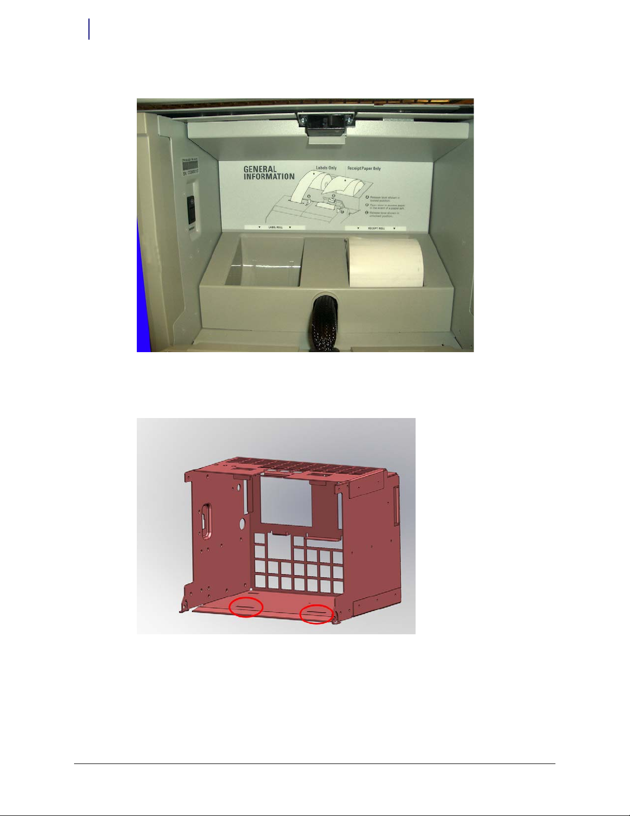
5. Remove the filter access door.
Figure 1-1. Remove the filter access panel
Domestic built PC Box consoles only have one set of mounting holes and need an adapter plate
(53-1214).
Figure 1-2. Domestic printer bay with one set of mounting holes
PC Box Consoles built in China (53-1218) will have two sets of mounting holes. The paper roll
holder could be mounted in the front or the back set, depending on revision level. If the printer
bay has two sets of mounting holes as shown in Figure 1-3 and the paper roll holder is
mounted in the rear-most set of mounting holes, skip to the first step of “Upgrade the Receipt
Printer” on page 1-7.
Page 7
© 2011 Omnicell, Inc. Med Label Printer Install Guide/67-2111 Rev A
Install the Med Label Printer on a PC Box Console 1-3
Prepare the Printer Bay
Figure 1-3. Off-shore printer bay with two sets of mounting holes
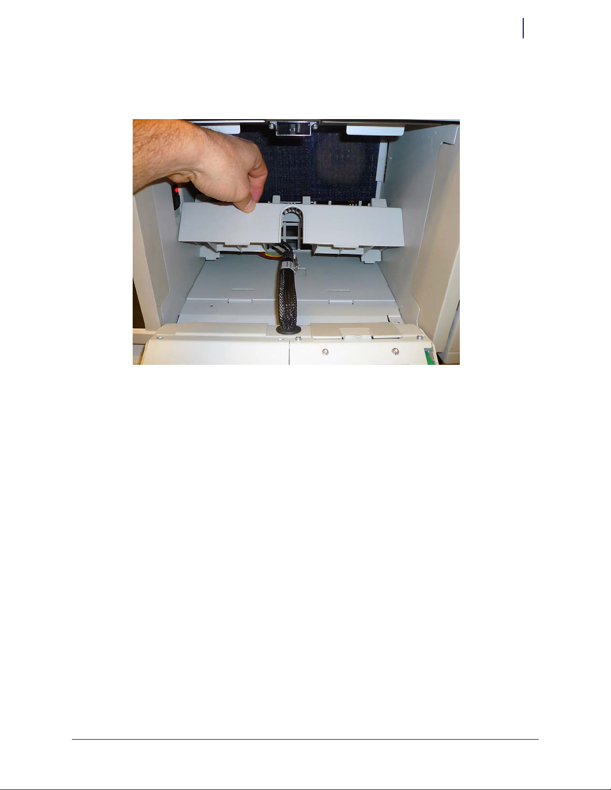
6. Gently push back on the front of the paper roll holder and lift the front of the holder from its
mounting holes.
Figure 1-4. Lift the front of the paper roll holder out from its mounting holes
Page 8
1-4 Install the Med Label Printer on a PC Box Console
Prepare the Printer Bay
Med Label Printer Install Guide/67-2111 Rev A © 2011 Omnicell, Inc.
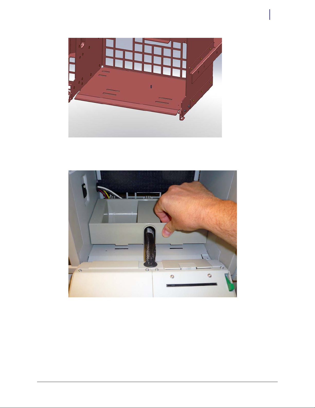
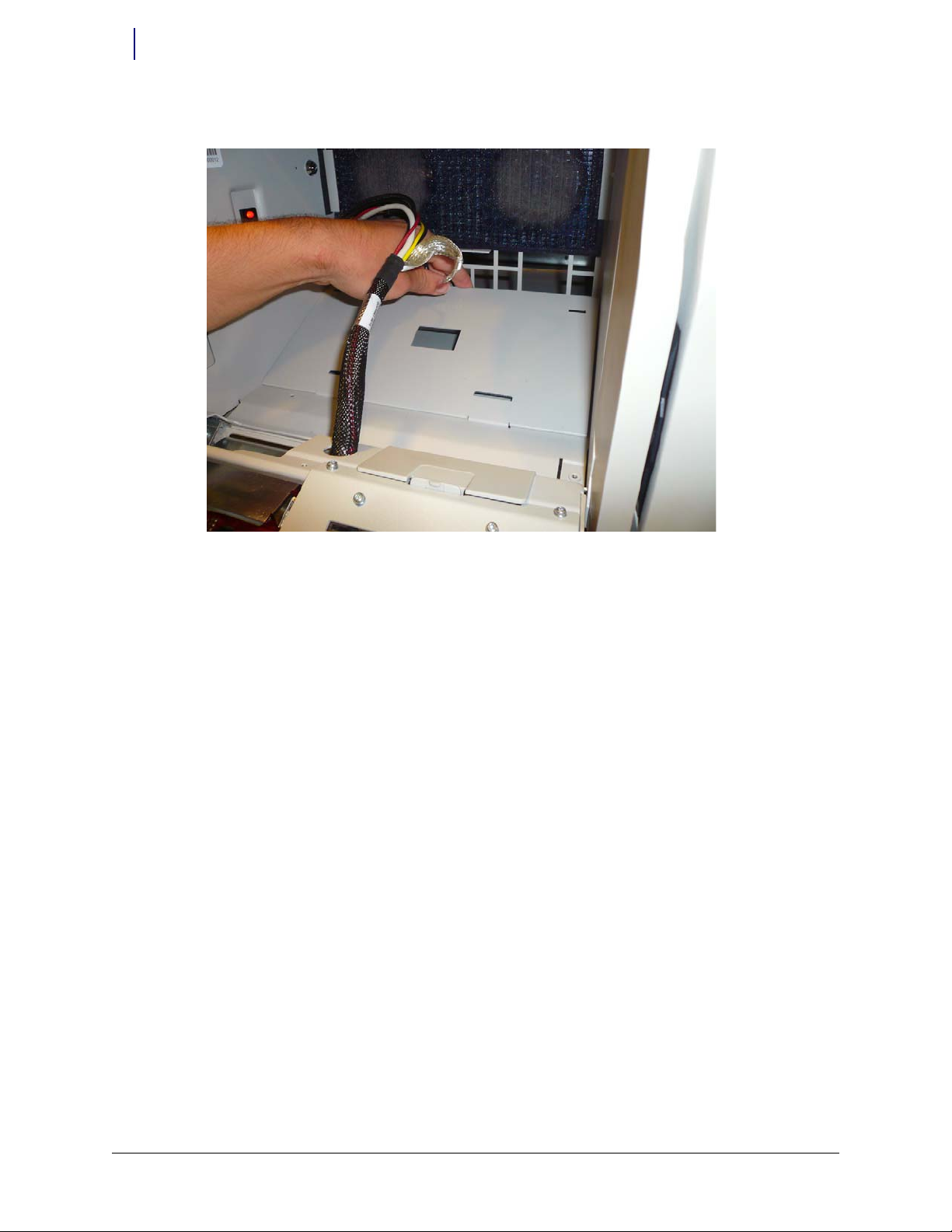
7. Lift the paper roll holder and remove it from the printer bay.
Figure 1-5. Remove the paper roll holder from the printer bay
8. Remove the nut or the nylon cable clamp that secures the ground cable to the bottom of the
printer bay and remove the ground cable. Use a 5.5 mm or 7/32” nut driver to remove the nut.
Figure 1-6. Remove the ground cable
Page 9
© 2011 Omnicell, Inc. Med Label Printer Install Guide/67-2111 Rev A
Install the Med Label Printer on a PC Box Console 1-5
Prepare the Printer Bay
9. Get the new adapter plate (53-1214) and remove the adhesive backs to expose the adhesive
tape.
Figure 1-7. Remove the backing from the adhesive tape on the new adapter plate
10. Slip the two tabs on the plate into the mounting holes nearest the front of the printer bay.
Figure 1-8. Place the adapter plate tabs into the mounting holes
Page 10
1-6 Install the Med Label Printer on a PC Box Console
Prepare the Printer Bay
Med Label Printer Install Guide/67-2111 Rev A © 2011 Omnicell, Inc.
11. Place the new adapter plate into place in the printer bay.
Figure 1-9. Add the adapter plate
12. Press down on the adapter plate to ensure it is secure in the bay.
13. Replace the ground or nylon cable clamp. Secure the nut using the 5.5 mm or 7/32” nut driver.
Page 11
© 2011 Omnicell, Inc. Med Label Printer Install Guide/67-2111 Rev A
Install the Med Label Printer on a PC Box Console 1-7
Prepare the Printer Bay
14. Place the new paper roll holder into the printer bay. Ensure the tabs on the bottom of the paper
roll holder are set into the mounting holes at the rear of the printer bay first and then the front
tabs are set into place.
Figure 1-10. Mount the new paper roll holder into the adapter plate
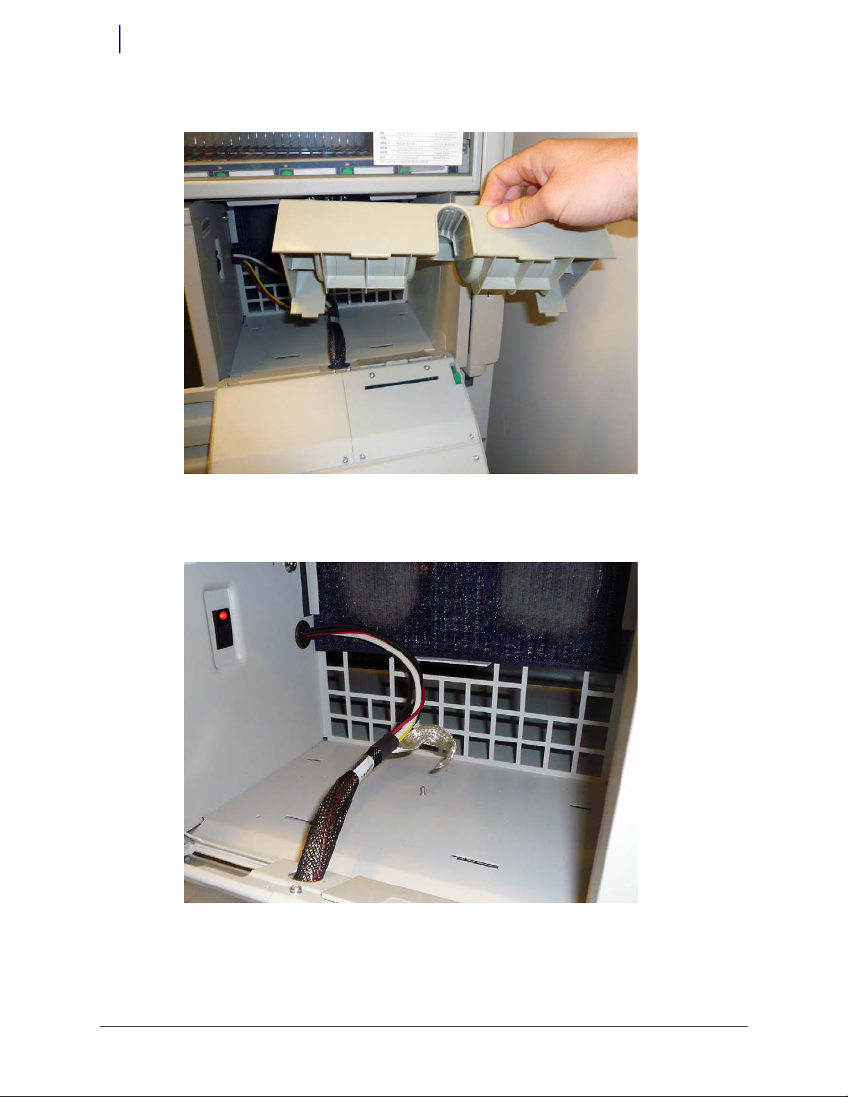
15. Add the new filter access door (53-1215).
Upgrade the Receipt Printer
Before continuing with the install of the med label printer, the receipt printer must be upgraded
with new parts to reduce electrostatic discharge (ESD) possibilities.
Page 12
1-8 Install the Med Label Printer on a PC Box Console
Prepare the Printer Bay
Med Label Printer Install Guide/67-2111 Rev A © 2011 Omnicell, Inc.
1. Remove the printer access door from the receipt printer.
Figure 1-11. Remove the printer access door.
2. Remove the four screws that secure the rear cover of the receipt printer. Use a Torx T10 driver.
Figure 1-12. Remove the four screws that secure the printer cover
Page 13
© 2011 Omnicell, Inc. Med Label Printer Install Guide/67-2111 Rev A
Install the Med Label Printer on a PC Box Console 1-9
Prepare the Printer Bay
3. Lift the receipt printer from the printer door.
Figure 1-13. Lift the receipt printer from the door
4. Turn the printer face up and set the printer assembly back down on the printer door assembly.
Figure 1-14. Set the receipt printer down on the printer access door
Important: The receipt printer is connected to the hub board via the power and USB cables. Do not attempt
to pull the receipt printer too far away from the console as it may damage the printer or the console.
Page 14
1-10 Install the Med Label Printer on a PC Box Console
Prepare the Printer Bay
Med Label Printer Install Guide/67-2111 Rev A © 2011 Omnicell, Inc.
5. Loosen, but do not remove, the two screws that secure the middle paper guide to the receipt
printer. Use a Torx T8 driver.
Figure 1-15. Remove the two screws that secure the middle printer bracket
6. Remove the bottom paper guide from the receipt printer.
Figure 1-16. Remove the middle bracket on the receipt printer
Page 15
© 2011 Omnicell, Inc. Med Label Printer Install Guide/67-2111 Rev A
Install the Med Label Printer on a PC Box Console 1-11
Prepare the Printer Bay
7. Place the new paper guide with ground cable (15-1050) into place on the receipt printer.
Figure 1-17. Add the new middle pr inter bracket
8. Tighten the two screws that secure the middle paper guide to the receipt printer. Use a Torx T8
driver.
9. Remove the ground nut in the printer bay. Use a 5.5 mm nut driver.
Figure 1-18. Remove the ground nut in the printer bay
Page 16
1-12 Install the Med Label Printer on a PC Box Console
Prepare the Printer Bay
Med Label Printer Install Guide/67-2111 Rev A © 2011 Omnicell, Inc.
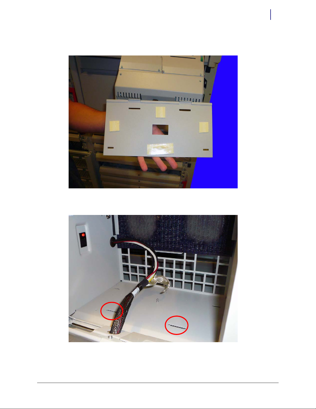
10. Place the receipt printer ground cable onto the grounding bolt and replace the nut.
Figure 1-19. Ground the printer to the console
11. Replace the printer ensuring that the new ground cable does not get pinched between the
printer cover and the door assembly.
Figure 1-20. Replace the printer
Page 17
© 2011 Omnicell, Inc. Med Label Printer Install Guide/67-2111 Rev A
Install the Med Label Printer on a PC Box Console 1-13
Prepare the Printer Bay
12. Secure the two screws closest to the PC Box Console first, as they align the printer guide. Use a
To r x T 10 d r i ve r.
Figure 1-21. Replace the top two screws first
13. Secure the bottom two screws next.
Figure 1-22. Replace the bottom screws last
Page 18

1-14 Install the Med Label Printer on a PC Box Console
Prepare the Printer Bay
Med Label Printer Install Guide/67-2111 Rev A © 2011 Omnicell, Inc.
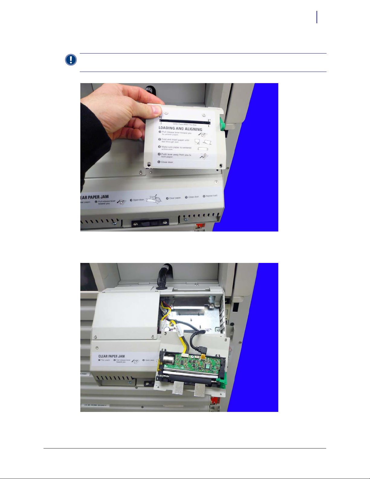
14. Replace the printer access door.
Figure 1-23. Replace the printer access door
Prepare the Printer Area
1. Remove the six screws (94-7721-06) that secure the rear cover on the console door. Use a Torx
T10 driver.
Figure 1-24. Remove the screws that secure the rear cover
Page 19
© 2011 Omnicell, Inc. Med Label Printer Install Guide/67-2111 Rev A
Install the Med Label Printer on a PC Box Console 1-15
Prepare the Printer Bay
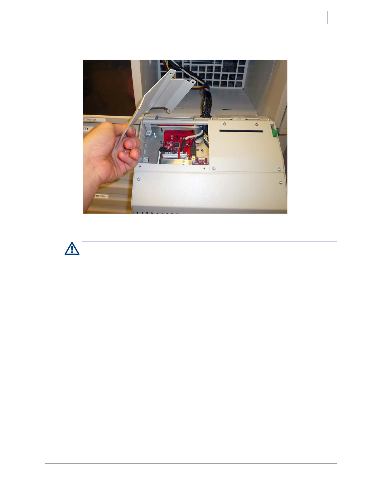
2. Remove the rear cover.
Figure 1-25. Remove the rear cover
3. Replace the two rear-most screws.
Caution: Use a ground strap and ensure that the strap is grounded to the cabinet before proceeding.
Page 20

1-16 Install the Med Label Printer on a PC Box Console
Prepare the Printer Bay
Med Label Printer Install Guide/67-2111 Rev A © 2011 Omnicell, Inc.
4. To avoid the possibility of shorting out the keyboard PCB, disconnect power to the keyboard
PCB by unplugging the power cable from J1 on the hub board.
Figure 1-26. Disconnect the keyboard power
5. Set the upper paper guide (15-2050) on top of the standoffs in the printer area.
Figure 1-27. Set the upper paper guide into place
Page 21

© 2011 Omnicell, Inc. Med Label Printer Install Guide/67-2111 Rev A
Install the Med Label Printer on a PC Box Console 1-17
Add the New Label Printer
6. Secure the upper paper guide with the two screws provided. Use a Torx T10 driver.
Figure 1-28. Secure the upper paper guide to the standoffs
Add the New Label Printer
1. Reconnect the keyboard power cable.
Note: Do not fully tighten these screws as the upper paper guide may need to be adjusted.
Important: Before fully tightening the upper paper guide, ensure that the leading edge of the paper guide is
flush with the front of the bezel opening, evenly installed and tight against the upper lip of the opening. It
may take multiple alignment attempts before the proper alignment is reached.
Page 22

1-18 Install the Med Label Printer on a PC Box Console
Add the New Label Printer
Med Label Printer Install Guide/67-2111 Rev A © 2011 Omnicell, Inc.
2. Hold the label printer assembly over the opening in the console door.
Figure 1-29. Set the label printer assembly in place
3. Connect the power cable to J9 on the hub board. Note the color orientation in Figure 1-30.
Figure 1-30. Connect the power ca ble
Important: When connecting the power cable, it is important to avoid seating the connector by pushing on
the wires. Pushing on the wires will damage the crimps. Ensure that you seat the connector by pushing on the
connector body itself, and not the wires.
Page 23

© 2011 Omnicell, Inc. Med Label Printer Install Guide/67-2111 Rev A
Install the Med Label Printer on a PC Box Console 1-19
Add the New Label Printer
4. Connect the USB cable to the bottom USB connector on the hub board.
Figure 1-31. Connect the USB cable
5. Set the label printer assembly into place on the console door and insert the four screws (947721-06) that secure the printer to the door.
Important:
Do not fully tighten the screws as the tightening sequence is important.
Page 24

1-20 Install the Med Label Printer on a PC Box Console
Add the New Label Printer
Med Label Printer Install Guide/67-2111 Rev A © 2011 Omnicell, Inc.
6. Tighten the two top screws (shown in Figure 1-32) first. These two screws align the assembly.
Figure 1-32. Tighte n the two rear scre ws first
7. Tighten the two screws shown in Figure 1-33 last.
Figure 1-33. Put the two front screws into place
Page 25

© 2011 Omnicell, Inc. Med Label Printer Install Guide/67-2111 Rev A
Install the Med Label Printer on a PC Box Console 1-21
Add the New Label Printer
8. Snap the printer access door into place in the opening on the door.
Figure 1-34. Snap the printer access door into place
Button up the Printer Bay
1. Power on the cabinet.
2. Insert the spindle into the label roll.
Figure 1-35. Insert the spindle into the roll of labels
Page 26

1-22 Install the Med Label Printer on a PC Box Console
Add the New Label Printer
Med Label Printer Install Guide/67-2111 Rev A © 2011 Omnicell, Inc.
3. Place the label roll and spindle into the left-hand side of the paper roll holder.
Figure 1-36. Ensure the labels are facing up as they come from the spool
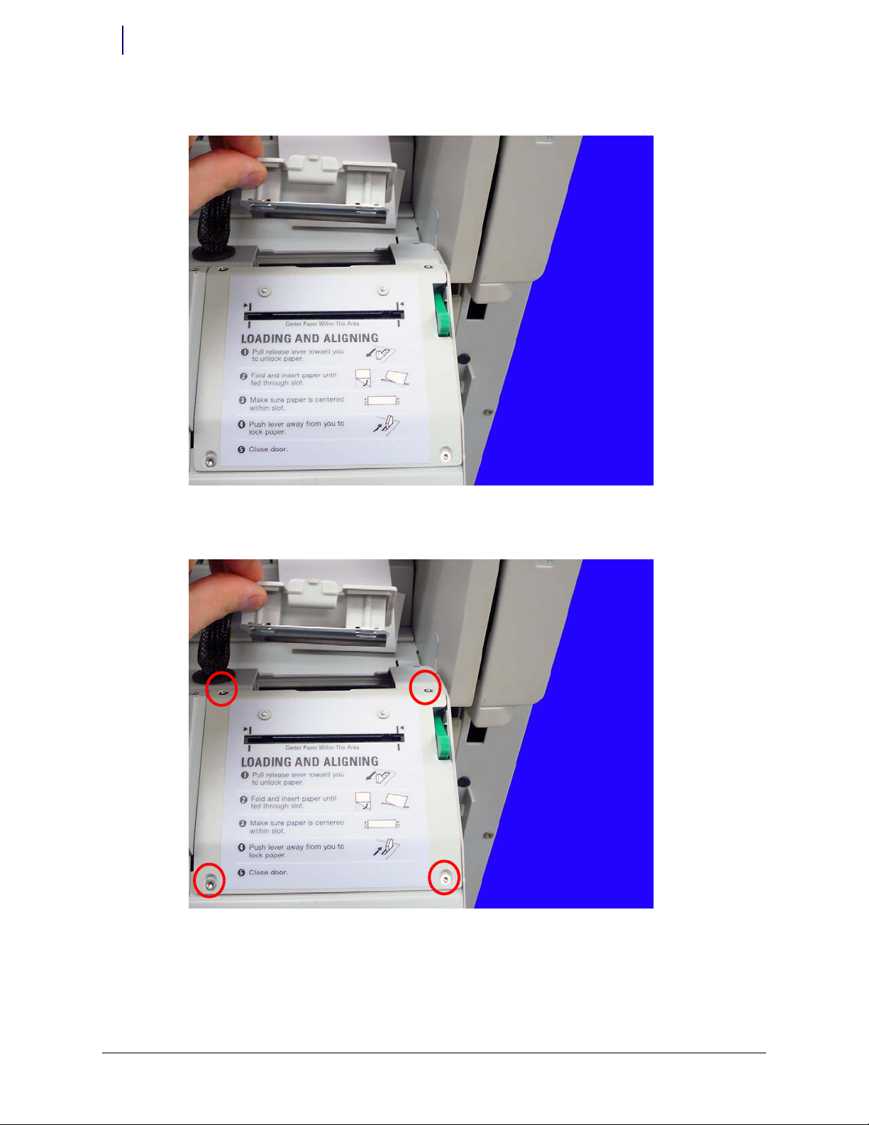
4. Make sure the release lever is in locked position, pushed away from the user. Feed the labels
into the slot of the label printer assembly.
Figure 1-37. Insert the labels into the label printer assembly
Important: Ensure the labels are facing up.
Page 27

© 2011 Omnicell, Inc. Med Label Printer Install Guide/67-2111 Rev A
Install the Med Label Printer on a PC Box Console 1-23
Add the New Label Printer
5. Replace and reload the receipt printer paper.
Check the Configurations
1. Restart the console.
2. Close the console door. Tighten the slack on the paper rolls while closing the door.
3. Once the console has completely rebooted, ensure that the med label printer is configured
properly.
a. Press Admin menus.
b. Press Omni Config.
c. Press Printers category.
d. Press Label Printer.
e. Make sure Label Printer support is set to Yes.
Figure 1-38. Ensure that label printer support is set to yes.
4. Test the printers to ensure they are working properly.
Note:
If the test label is blank, retry the test.
Page 28

1-24 Install the Med Label Printer on a PC Box Console
Add the New Label Printer
Med Label Printer Install Guide/67-2111 Rev A © 2011 Omnicell, Inc.
Page 29

© 2011 Omnicell, Inc. Med Label Printer Install Guide/67-2111 Rev A
Install a Med Label Printer on an OmniRx 2-1
Tools List
Install a Med Label Printer on an
OmniRx
Tools List
The following tools are required to install the Med Label Printer:
T10 Torx driver
T8 Torx driver
Xacto knife or cutters
P5.5mm nut driver (7/32” also works)
P6mm nut driver (1/4" also works)
Flat head screwdriver
Prepare the Printer Bay
1. Perform a graceful shutdown of the console.
2. Unplug the power and network cables from the rear of the OmniRx.
3. Use key #2378 to unlock the lid on the OmniRx.
Figure 2-1. Unlock the lid
Page 30

2-2 Install a Med Label Printer on an OmniRx
Prepare the Printer Bay
Med Label Printer Install Guide/67-2111 Rev A © 2011 Omnicell, Inc.
4. Open the lid and secure it in place with the lock bracket (if available) or completely remove the
lid and set it aside.
5. Unplug the power from the E-Box.
Figure 2-2. Unplug the power from the E-Box
6. Open the printer door.
7. Pull the platen lever up and pull the receipt paper from the printer.
Figure 2-3. Open the platen level
Page 31

© 2011 Omnicell, Inc. Med Label Printer Install Guide/67-2111 Rev A
Install a Med Label Printer on an OmniRx 2-3
Prepare the Printer Bay
8. Remove the paper from its holder.
Figure 2-4. Remove the receipt printer paper
9. Remove the paper tray from the OmniRx.
Figure 2-5. Remove the paper tray
Page 32

2-4 Install a Med Label Printer on an OmniRx
Prepare the Printer Bay
Med Label Printer Install Guide/67-2111 Rev A © 2011 Omnicell, Inc.
Remove the Keyboard
In certain cases, the USB cable that attaches to the med label printer may already be installed. If
the cable is installed and accessible, please proceed to “Prepare the Med Label Printer for Install”
on page 2-11.
1. Remove the two inner screws on the under side of the OmniRx G4 console that secure the
keyboard. Use a Torx T10 driver.
Figure 2-6. Remove the bottom two keyboard screws
Page 33

© 2011 Omnicell, Inc. Med Label Printer Install Guide/67-2111 Rev A
Install a Med Label Printer on an OmniRx 2-5
Prepare the Printer Bay
2. Remove the cosmetic screw cover above the keyboard on the OmniRx. Use a thin flat head
screwdriver to lift the cover if necessary.
Figure 2-7. Remove the cosmetic screw cover
3. Remove the four screws on the keyboard tray that secure the keyboard to the console. Use a
To r x T 10 d r i ve r.
Figure 2-8. Remove the top four screws that secure the keyboard
Page 34

2-6 Install a Med Label Printer on an OmniRx
Prepare the Printer Bay
Med Label Printer Install Guide/67-2111 Rev A © 2011 Omnicell, Inc.
4. Lift and remove the keyboard from the G4 console. Set the keyboard aside.
Figure 2-9. Lift and remove the keyboard
Page 35

© 2011 Omnicell, Inc. Med Label Printer Install Guide/67-2111 Rev A
Install a Med Label Printer on an OmniRx 2-7
Remove the Receipt Printer
Remove the Receipt Printer
Remove the Printer Bezel
1. Remove the three screws securing the printer bezel. Use a Torx T10 driver.
Figure 2-10. Remove the screws securing the printer bezel
Page 36

2-8 Install a Med Label Printer on an OmniRx
Remove the Receipt Printer
Med Label Printer Install Guide/67-2111 Rev A © 2011 Omnicell, Inc.
2. Pull the printer bezel from the printer bay wall. Clip the zip tie that secures the cables to the
bezel and set it down inside the printer bay.
Figure 2-11. Pull the printer bezel from the printer bay wall
3. Remove the eight screws that secure the paper guides to the OmniRx frame.
Figure 2-12. Remove the eight screws that secure the paper guides
Note: Do not disconnect the receipt printer power cable or attempt to remove the receipt printer from the
bezel yet.
Page 37

© 2011 Omnicell, Inc. Med Label Printer Install Guide/67-2111 Rev A
Install a Med Label Printer on an OmniRx 2-9
Remove the Receipt Printer
4. Remove the nut that secures the ground wire to the OmniRx frame. Use a 5.5mm or 7/32” nut
driver.
Figure 2-13. Remove the ground nut
5. Remove both paper alignment guides. The bottom guide may need to be bent to remove it
from the frame. Neither guide will not be re-used so it is safe to bend them if necessary.
Page 38

2-10 Install a Med Label Printer on an OmniRx
Remove the Receipt Printer
Med Label Printer Install Guide/67-2111 Rev A © 2011 Omnicell, Inc.
Route the Printer USB Cable
1. Feed the new USB cable (42-1332) through the opening under the keyboard and route the
cable toward the back of the E-Box enclosure.
Figure 2-14. Fee d the U SB cab le throu gh the openin g
2. Plug the USB cable into the E-Box connection marked “USB 2 LABEL PTR” or “USB2”
depending on the label on the side of the E-Box.
Figure 2-15. Plug the USB cable into the proper location on the E-Box
Page 39

© 2011 Omnicell, Inc. Med Label Printer Install Guide/67-2111 Rev A
Install a Med Label Printer on an OmniRx 2-11
Prepare the Med Label Printer for Install
3. Route the USB cable into the cable guides on the side of the E-Box.
Figure 2-16. Route the USB cable using the cable guides on the side of the E-Box
Prepare the Med Label Printer for Install
Two n ew p ap er g ui de s ( Figure 2-17) replace the existing top and bottom paper guides. The guide
on the left (54-2511) is the guide for the new med label printer; the guide on the right (54-2412) is
for the existing receipt printer.
Figure 2-17. The new med labe l and receipt print er paper guides, respe ctively
Page 40

2-12 Install a Med Label Printer on an OmniRx
Prepare the Med Label Printer for Install
Med Label Printer Install Guide/67-2111 Rev A © 2011 Omnicell, Inc.
1. Place the med label and receipt printer guides into the opening on the OmniRx as shown in
Figure 2-18.
2.
Figure 2-18. Place the med label printer guides in the opening
Note: If the guides are not easily installed into the opening on the front of the OmniRx, try inserting a corner
first and then sliding the guide into place.
Page 41

© 2011 Omnicell, Inc. Med Label Printer Install Guide/67-2111 Rev A
Install a Med Label Printer on an OmniRx 2-13
Prepare the Med Label Printer for Install
3. Ensure that the paper guides are flush with the opening in the front of the OmniRx.
Figure 2-19. Ensure the paper guides are flush with the opening in the front of the OmniRx
4. Ensure that the grounding tab of the label guide sits on top of the grounding tab of the receipt
guide. Insert a screw (94-8321-05) into the grounding tab to secure the guides to the frame.
Figure 2-20. Ensure the grounding tabs are placed correctly.
Page 42

2-14 Install a Med Label Printer on an OmniRx
Prepare the Med Label Printer for Install
Med Label Printer Install Guide/67-2111 Rev A © 2011 Omnicell, Inc.
5. Attach the ground cable to the indicated screw (94-8321-05) and secure the screw to paper
guide.
Figure 2-21. Atta ch the grou nd wire and the screw to the paper guide location shown
6. Secure the paper guides and the ground cable with the screws provided (94-8321-05). Do not
tighten any screws until all the screws are installed.
Page 43

© 2011 Omnicell, Inc. Med Label Printer Install Guide/67-2111 Rev A
Install a Med Label Printer on an OmniRx 2-15
Prepare the Med Label Printer for Install
7. Ensure that the outer two tabs are completely broken off the front of the lid. If the tabs are
present, use a pair of cutters or an X-Acto knife to completely remove the tabs.
Figure 2-22. Break off the two outside tabs
8. Ensure that the tabs are completely broken off.
Figure 2-23. Ensure the tab is completely broken off
Note: It is not necessary to remove the center tab.
Page 44

2-16 Install a Med Label Printer on an OmniRx
Install the Med label Printer
Med Label Printer Install Guide/67-2111 Rev A © 2011 Omnicell, Inc.
Install the Med label Printer
1. Add the three standoffs (94-6329) to the OmniRx frame. Use a P6mm or 1/4” nut driver.
Figure 2-24. Add the st andoffs
Important: Do not over-tighten the standoffs.
Page 45

© 2011 Omnicell, Inc. Med Label Printer Install Guide/67-2111 Rev A
Install a Med Label Printer on an OmniRx 2-17
Install the Med label Printer
2. Ensure that the lever scoop on the bezel is removed. If this scoop is present, the bezel will need
to be replaced with a new one (57-1328).
Figure 2-25. Ensure the lever scoop is removed
3. Remove the receipt printer and cables from the existing bezel.
4. Using the existing screws, install the receipt printer onto the new bezel, ensuring that all cables
are routed behind the printer and are not pinched. Use a Torx T8 driver.
Page 46

2-18 Install a Med Label Printer on an OmniRx
Install the Med label Printer
Med Label Printer Install Guide/67-2111 Rev A © 2011 Omnicell, Inc.
5. Connect the power cable to the med label printer (70-7005).
Figure 2-26. Conn ect the powe r cable to t he med l abel pr inter
6. Connect the USB cable to the rear of the med label printer.
Figure 2-27. Connect the USB cable to the p rinter
Important: The USB connection MUST be placed in the correct location on the printer. Use Figure 2-27 on
page 2-18 for reference.
Page 47

© 2011 Omnicell, Inc. Med Label Printer Install Guide/67-2111 Rev A
Install a Med Label Printer on an OmniRx 2-19
Install the Med label Printer
Mount the Med Label Printer onto the Printer Bezel
1. Route the receipt printer cables as shown in Figure 2-28 on page 2-19.
Figure 2-28. Move the receipt printer cables out of the way
2. Set the med label printer into place on the bezel.
Figure 2-29. Set the med label printer into place
Important: Ensure that the receipt printer cables are not pinched by the med label printer.
Page 48

2-20 Install a Med Label Printer on an OmniRx
Install the Med label Printer
Med Label Printer Install Guide/67-2111 Rev A © 2011 Omnicell, Inc.
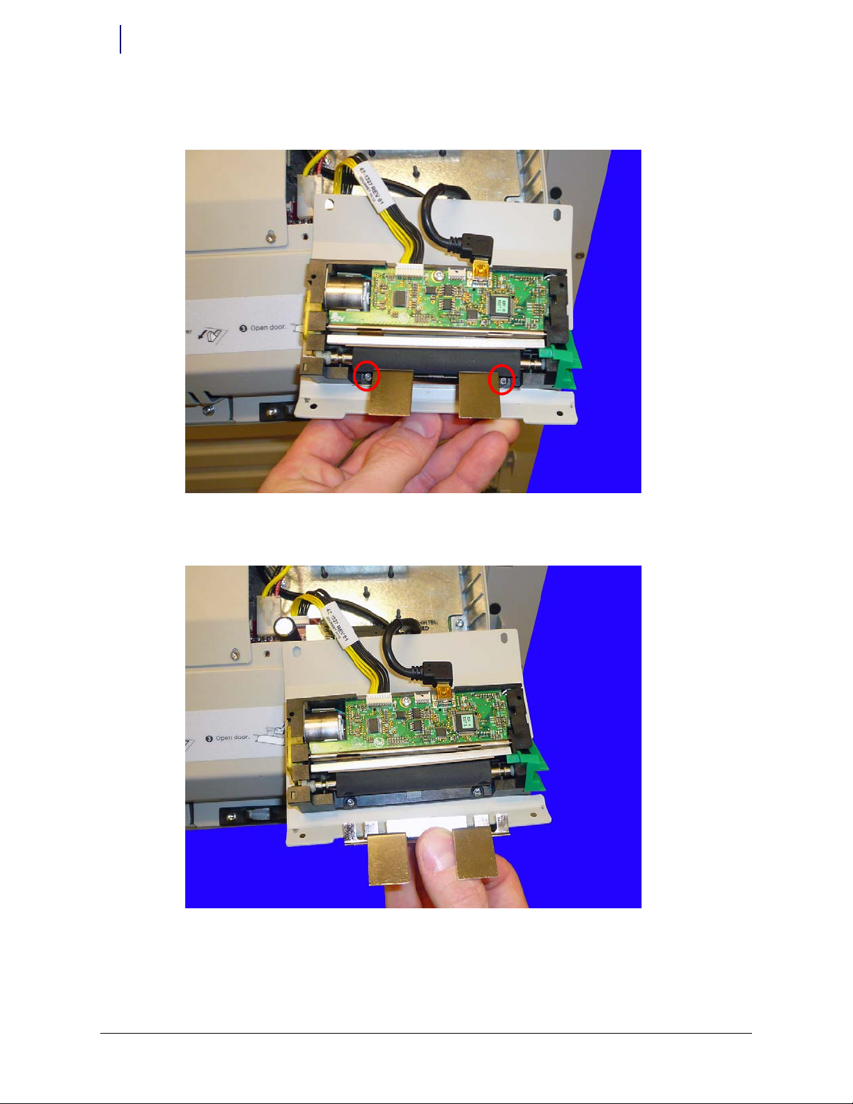
3. To access the screw holes, pull the tab on the left side of the printer away from the printer and
pull up on the cutter.
Figure 2-30. Open the med label printer rollers
4. Insert the screws (94-7411-06) to secure the med label printer to the printer bezel. Use a Torx
T8 driver.
Figure 2-31. Secure the printer with the screws provided
5. Close the med label printer securely.
Page 49

© 2011 Omnicell, Inc. Med Label Printer Install Guide/67-2111 Rev A
Install a Med Label Printer on an OmniRx 2-21
Install the Med label Printer
Tes t the M ed La bel Pr int er
1. Plug the power cable into the E-Box.
2. Plug the power and network cables into the rear of the OmniRx.
3. Power on the OmniRx.
4. Once the system is powered up, check to ensure that the two green lights at the top of the med
label printer and the receipt printer are lit up.
5. Restart the OmniRx.
6. Once the console has completely rebooted, ensure that the med label printer is configured
properly.
a. Press Admin menus.
b. Press Omni Config.
c. Press Printers category.
d. Press Label Printer.
e. Make sure Label Printer support is set to Yes.
Figure 2-32. Ensure that the Label Printer Support is set to Yes
7. Test the printers to ensure they are working properly.
Note:
If the test label is blank, retry the test.
Page 50

2-22 Install a Med Label Printer on an OmniRx
Install the Med label Printer
Med Label Printer Install Guide/67-2111 Rev A © 2011 Omnicell, Inc.
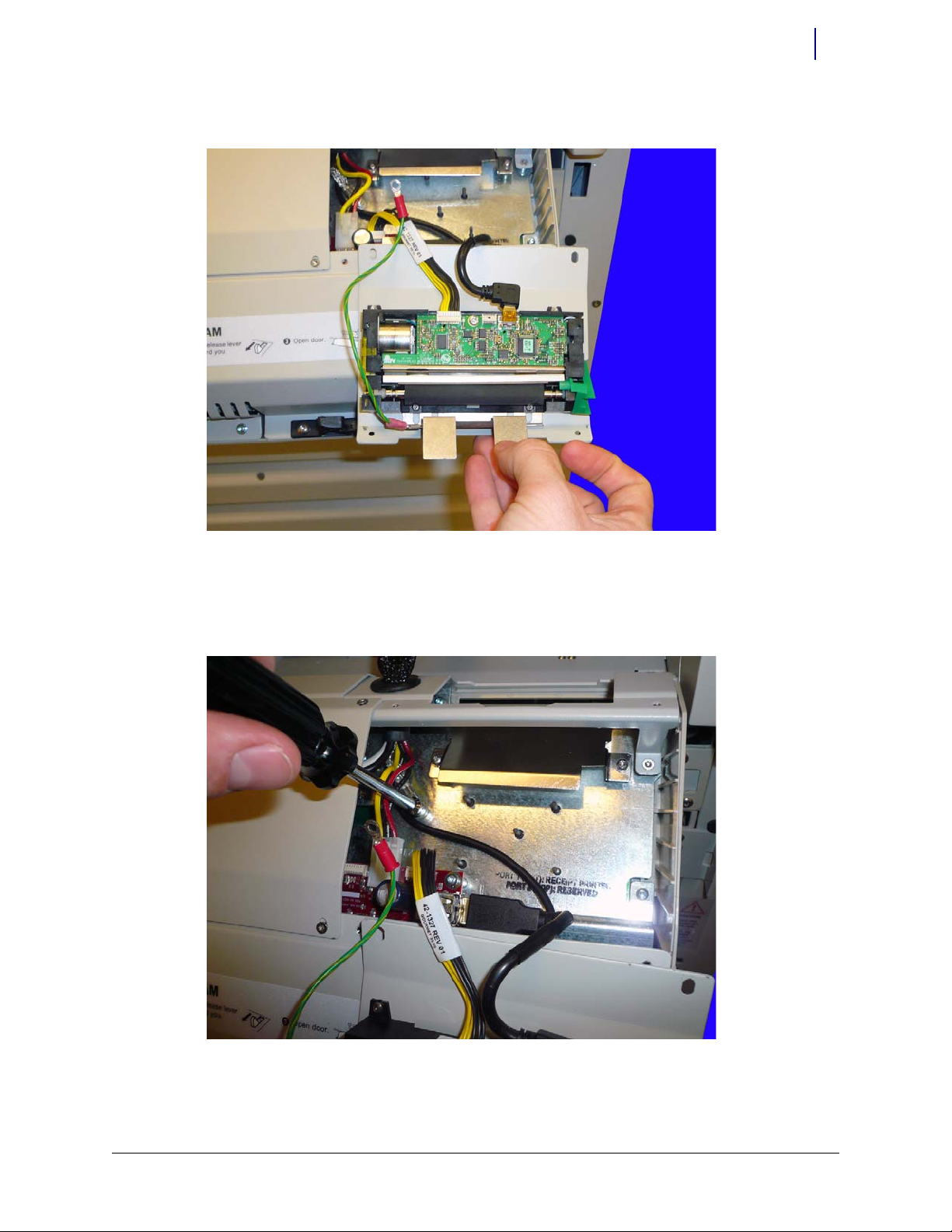
Replace the Removed Pieces
1. Slide the printer bezel assembly into place. Ensure that no wires are sticking out or are being
pinched.
Figure 2-33. Ensure that all the printer wires are safely in place
Page 51

© 2011 Omnicell, Inc. Med Label Printer Install Guide/67-2111 Rev A
Install a Med Label Printer on an OmniRx 2-23
Install the Med label Printer
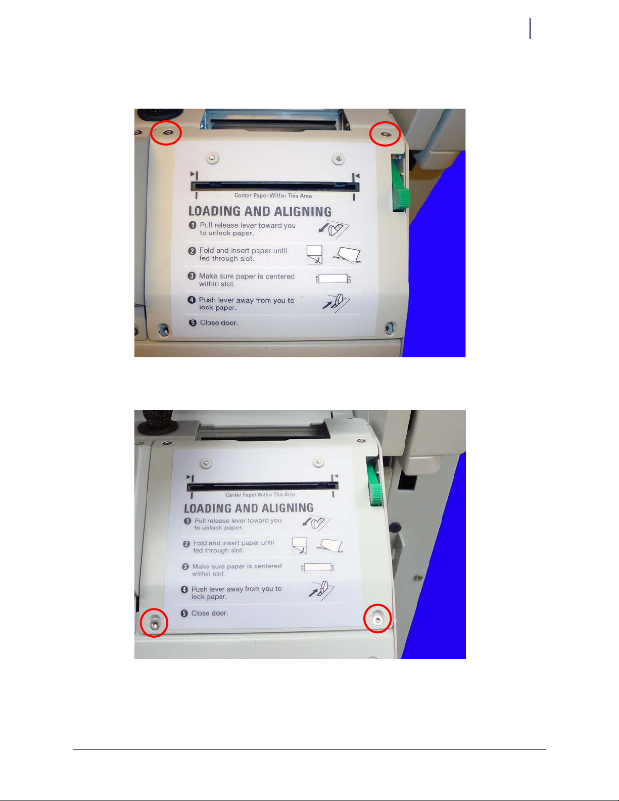
2. Add the three screws (94-8321-05) that secure the printer bezel assembly to the OmniRx frame
so that the screws are slightly engaged. Do not tighten the screws. Use a Torx T10 driver.
Figure 2-34. Add the three screws that secure the printe r alignment guide to the OmniRx fr ame
Note: The screw on the far right of Figure 2-34 is the hardest to access. Install this screw first.
Page 52

2-24 Install a Med Label Printer on an OmniRx
Install the Med label Printer
Med Label Printer Install Guide/67-2111 Rev A © 2011 Omnicell, Inc.
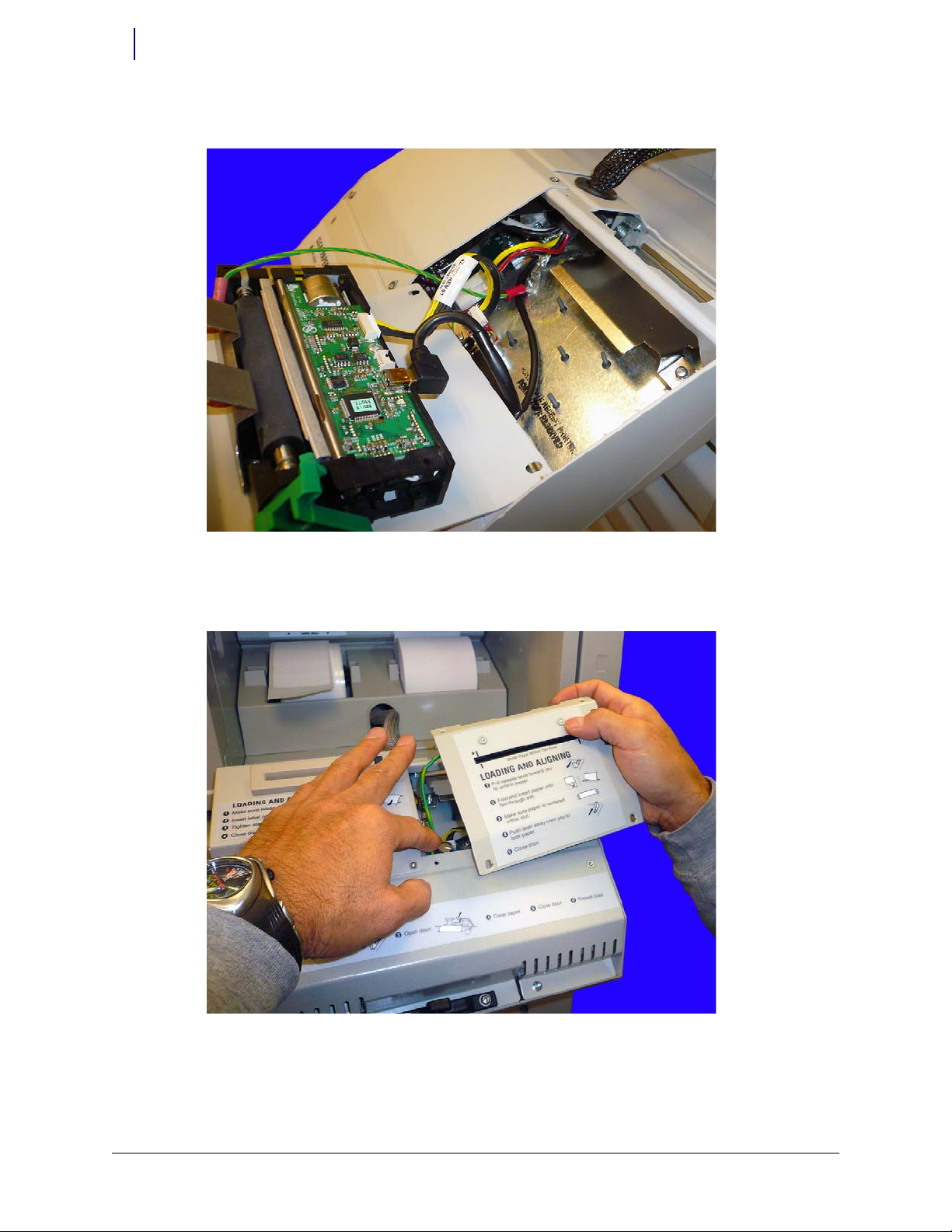
3. Slide the cover (54-8207) into place, ensuring that cables are not being pinched and top
surfaces are flush.
Figure 2-35. Add the cosmetic printer cove r
4. Tighten the three screws.
5. Add in the new paper tray (57-1329) to the printer bay.
Figure 2-36. Add in the new printer tray
Page 53

© 2011 Omnicell, Inc. Med Label Printer Install Guide/67-2111 Rev A
Install a Med Label Printer on an OmniRx 2-25
Install the Med label Printer
6. Remove the adhesive liner from the label (65-1143) and install it to inside of the printer bay
door (on top of the existing label).
Figure 2-37. Add the new label
7. Completely remove the tape from the med label roll (95-6078-40). Place the spindle (51-5150)
into the med label roll and place the roll into the paper tray.
8. Place the receipt printer spindle (51-5151) into the receipt printer paper roll and place the
receipt paper roll into the paper tray.
9. Ensure that both labels and receipt are coming from the top of the roll.
Page 54

2-26 Install a Med Label Printer on an OmniRx
Install the Med label Printer
Med Label Printer Install Guide/67-2111 Rev A © 2011 Omnicell, Inc.
10. Ensure the printer platen levers are down. Feed the labels into the printer until the printer
grabs the label paper.
Figure 2-38. Add the paper rol ls
11. Feed the receipt printer paper into the printer until the printer grabs the paper.
Tes t the P rint er
1. Run a sample med label and receipt print to ensure the printers are working properly before
closing the lid.
2. Close the printer bay lid.
Page 55

© 2011 Omnicell, Inc. Med Label Printer Install Guide/67-2111 Rev A
Install a Med Label Printer on an OmniRx 2-27
Replace OmniRx Pieces
Replace OmniRx Pieces
Replace the G4 OmniRx Lid
1. Lift the OmniRx lid onto the back of the machine and set the lid down, ensuring that it rests on
the console frame pegs.
Figure 2-39. Place the lid onto the pegs on the frame of the OmniRx
Figure 2-40. Set the lid down on the frame pegs
Page 56

2-28 Install a Med Label Printer on an OmniRx
Replace OmniRx Pieces
Med Label Printer Install Guide/67-2111 Rev A © 2011 Omnicell, Inc.
2. Set the lid down gently and use the #2378 cam lock key to lock the lid.
Figure 2-41. Close and lock the lid
Replace the Keyboard
1. Set the keyboard back into place and secure the top four screws that had previously been
replaced. Use a Torx T10 driver.
Figure 2-42. Replace the keyboard
Page 57

© 2011 Omnicell, Inc. Med Label Printer Install Guide/67-2111 Rev A
Install a Med Label Printer on an OmniRx 2-29
Replace OmniRx Pieces
2. Replace the cosmetic cover.
Figure 2-43. Replace the cosmetic cover
3. Replace the bottom two screws. Use a Torx T10 driver.
Figure 2-44. Replace the two screws
Page 58

2-30 Install a Med Label Printer on an OmniRx
Replace OmniRx Pieces
Med Label Printer Install Guide/67-2111 Rev A © 2011 Omnicell, Inc.
Page 59

© 2011 Omnicell, Inc. Med Label Printer Install Guide/67-2111 Rev A
31
List of Figures
Figure 1-1: Remove the filter access panel . . . . . . . . . . . . . . . . . . . . . . . . . . . . . . . . . . . . . . . . 1-2
Figure 1-2: Domestic printer bay with one set of mounting holes . . . . . . . . . . . . . . . . . . . . 1-2
Figure 1-3: Off-shore printer bay with two sets of mounting holes . . . . . . . . . . . . . . . . . . . 1-3
Figure 1-4: Lift the front of the paper roll holder out from its mounting holes . . . . . . . . . 1-3
Figure 1-5: Remove the paper roll holder from the printer bay . . . . . . . . . . . . . . . . . . . . . . 1-4
Figure 1-6: Remove the ground cable . . . . . . . . . . . . . . . . . . . . . . . . . . . . . . . . . . . . . . . . . . . . 1-4
Figure 1-7: Remove the backing from the adhesive tape on the new adapter plate . . . . . . 1-5
Figure 1-8: Place the adapter plate tabs into the mounting holes . . . . . . . . . . . . . . . . . . . . . 1-5
Figure 1-9: Add the adapter plate . . . . . . . . . . . . . . . . . . . . . . . . . . . . . . . . . . . . . . . . . . . . . . . 1-6
Figure 1-10: Mount the new paper roll holder into the adapter plate . . . . . . . . . . . . . . . . . 1-7
Figure 1-11: Remove the printer access door. . . . . . . . . . . . . . . . . . . . . . . . . . . . . . . . . . . . . . 1-8
Figure 1-12: Remove the four screws that secure the printer cover . . . . . . . . . . . . . . . . . . . 1-8
Figure 1-13: Lift the receipt printer from the door . . . . . . . . . . . . . . . . . . . . . . . . . . . . . . . . . 1-9
Figure 1-14: Set the receipt printer down on the printer access door . . . . . . . . . . . . . . . . . 1-9
Figure 1-15: Remove the two screws that secure the middle printer bracket . . . . . . . . . . 1-10
Figure 1-16: Remove the middle bracket on the receipt printer . . . . . . . . . . . . . . . . . . . . . 1-10
Figure 1-17: Add the new middle printer bracket . . . . . . . . . . . . . . . . . . . . . . . . . . . . . . . . . 1-11
Figure 1-18: Remove the ground nut in the printer bay . . . . . . . . . . . . . . . . . . . . . . . . . . . 1-11
Figure 1-19: Ground the printer to the console . . . . . . . . . . . . . . . . . . . . . . . . . . . . . . . . . . 1-12
Figure 1-20: Replace the printer . . . . . . . . . . . . . . . . . . . . . . . . . . . . . . . . . . . . . . . . . . . . . . . 1-12
Figure 1-21: Replace the top two screws first . . . . . . . . . . . . . . . . . . . . . . . . . . . . . . . . . . . . . 1-13
Figure 1-22: Replace the bottom screws last . . . . . . . . . . . . . . . . . . . . . . . . . . . . . . . . . . . . . 1-13
Figure 1-23: Replace the printer access door . . . . . . . . . . . . . . . . . . . . . . . . . . . . . . . . . . . . . 1-14
Figure 1-24: Remove the screws that secure the rear cover . . . . . . . . . . . . . . . . . . . . . . . . . 1-14
Figure 1-25: Remove the rear cover . . . . . . . . . . . . . . . . . . . . . . . . . . . . . . . . . . . . . . . . . . . . 1-15
Figure 1-26: Disconnect the keyboard power . . . . . . . . . . . . . . . . . . . . . . . . . . . . . . . . . . . . 1-16
Figure 1-27: Set the upper paper guide into place . . . . . . . . . . . . . . . . . . . . . . . . . . . . . . . . . 1-16
Figure 1-28: Secure the upper paper guide to the standoffs . . . . . . . . . . . . . . . . . . . . . . . . 1-17
Figure 1-29: Set the label printer assembly in place . . . . . . . . . . . . . . . . . . . . . . . . . . . . . . . 1-18
Figure 1-30: Connect the power cable . . . . . . . . . . . . . . . . . . . . . . . . . . . . . . . . . . . . . . . . . . 1-18
Figure 1-31: Connect the USB cable . . . . . . . . . . . . . . . . . . . . . . . . . . . . . . . . . . . . . . . . . . . . 1-19
Figure 1-32: Tighten the two rear screws first . . . . . . . . . . . . . . . . . . . . . . . . . . . . . . . . . . . . 1-20
Figure 1-33: Put the two front screws into place . . . . . . . . . . . . . . . . . . . . . . . . . . . . . . . . . . 1-20
Figure 1-34: Snap the printer access door into place . . . . . . . . . . . . . . . . . . . . . . . . . . . . . . 1-21
Figure 1-35: Insert the spindle into the roll of labels . . . . . . . . . . . . . . . . . . . . . . . . . . . . . . 1-21
Figure 1-36: Ensure the labels are facing up as they come from the spool . . . . . . . . . . . . 1-22
Figure 1-37: Insert the labels into the label printer assembly . . . . . . . . . . . . . . . . . . . . . . . 1-22
Figure 1-38: Ensure that label printer support is set to yes. . . . . . . . . . . . . . . . . . . . . . . . . . 1-23
Figure 2-1: Unlock the lid . . . . . . . . . . . . . . . . . . . . . . . . . . . . . . . . . . . . . . . . . . . . . . . . . . . . . . 2-1
Figure 2-2: Unplug the power from the E-Box . . . . . . . . . . . . . . . . . . . . . . . . . . . . . . . . . . . . 2-2
Figure 2-3: Open the platen level. . . . . . . . . . . . . . . . . . . . . . . . . . . . . . . . . . . . . . . . . . . . . . . . 2-2
Figure 2-4: Remove the receipt printer paper . . . . . . . . . . . . . . . . . . . . . . . . . . . . . . . . . . . . . 2-3
Figure 2-5: Remove the paper tray . . . . . . . . . . . . . . . . . . . . . . . . . . . . . . . . . . . . . . . . . . . . . . 2-3
Figure 2-6: Remove the bottom two keyboard screws . . . . . . . . . . . . . . . . . . . . . . . . . . . . . . 2-4
Page 60

1-32
Med Label Printer Install Guide/67-2111 Rev A © 2011 Omnicell, Inc.
Figure 2-7: Remove the cosmetic screw cover . . . . . . . . . . . . . . . . . . . . . . . . . . . . . . . . . . . . . 2-5
Figure 2-8: Remove the top four screws that secure the keyboard . . . . . . . . . . . . . . . . . . . . 2-5
Figure 2-9: Lift and remove the keyboard . . . . . . . . . . . . . . . . . . . . . . . . . . . . . . . . . . . . . . . . 2-6
Figure 2-10: Remove the screws securing the printer bezel . . . . . . . . . . . . . . . . . . . . . . . . . . 2-7
Figure 2-11: Pull the printer bezel from the printer bay wall . . . . . . . . . . . . . . . . . . . . . . . . 2-8
Figure 2-12: Remove the eight screws that secure the paper guides . . . . . . . . . . . . . . . . . . . 2-8
Figure 2-13: Remove the ground nut . . . . . . . . . . . . . . . . . . . . . . . . . . . . . . . . . . . . . . . . . . . . 2-9
Figure 2-14: Feed the USB cable through the opening . . . . . . . . . . . . . . . . . . . . . . . . . . . . . 2-10
Figure 2-15: Plug the USB cable into the proper location on the E-Box . . . . . . . . . . . . . . 2-10
Figure 2-16: Route the USB cable using the cable guides on the side of the E-Box . . . . . 2-11
Figure 2-17: The new med label and receipt printer paper guides, respectively . . . . . . . . 2-11
Figure 2-18: Place the med label printer guides in the opening . . . . . . . . . . . . . . . . . . . . . 2-12
Figure 2-19: Ensure the paper guides are flush with the opening in the front of the OmniRx
2-13
Figure 2-20: Ensure the grounding tabs are placed correctly. . . . . . . . . . . . . . . . . . . . . . . . 2-13
Figure 2-21: Attach the ground wire and the screw to the paper guide location shown . 2-14
Figure 2-22: Break off the two outside tabs . . . . . . . . . . . . . . . . . . . . . . . . . . . . . . . . . . . . . . 2-15
Figure 2-23: Ensure the tab is completely broken off . . . . . . . . . . . . . . . . . . . . . . . . . . . . . . 2-15
Figure 2-24: Add the standoffs . . . . . . . . . . . . . . . . . . . . . . . . . . . . . . . . . . . . . . . . . . . . . . . . . 2-16
Figure 2-25: Ensure the lever scoop is removed . . . . . . . . . . . . . . . . . . . . . . . . . . . . . . . . . . 2-17
Figure 2-26: Connect the power cable to the med label printer . . . . . . . . . . . . . . . . . . . . . 2-18
Figure 2-27: Connect the USB cable to the printer . . . . . . . . . . . . . . . . . . . . . . . . . . . . . . . . 2-18
Figure 2-28: Move the receipt printer cables out of the way . . . . . . . . . . . . . . . . . . . . . . . . 2-19
Figure 2-29: Set the med label printer into place . . . . . . . . . . . . . . . . . . . . . . . . . . . . . . . . . 2-19
Figure 2-30: Open the med label printer rollers . . . . . . . . . . . . . . . . . . . . . . . . . . . . . . . . . . 2-20
Figure 2-31: Secure the printer with the screws provided . . . . . . . . . . . . . . . . . . . . . . . . . . 2-20
Figure 2-32: Ensure that the Label Printer Support is set to Yes . . . . . . . . . . . . . . . . . . . . 2-21
Figure 2-33: Ensure that all the printer wires are safely in place . . . . . . . . . . . . . . . . . . . . 2-22
Figure 2-34: Add the three screws that secure the printer alignment guide to the OmniRx
frame . . . . . . . . . . . . . . . . . . . . . . . . . . . . . . . . . . . . . . . . . . . . . . . . . . . . . . . . . . . . . . . . . . . . 2-23
Figure 2-35: Add the cosmetic printer cover . . . . . . . . . . . . . . . . . . . . . . . . . . . . . . . . . . . . . 2-24
Figure 2-36: Add in the new printer tray . . . . . . . . . . . . . . . . . . . . . . . . . . . . . . . . . . . . . . . . 2-24
Figure 2-37: Add the new label . . . . . . . . . . . . . . . . . . . . . . . . . . . . . . . . . . . . . . . . . . . . . . . . 2-25
Figure 2-38: Add the paper rolls . . . . . . . . . . . . . . . . . . . . . . . . . . . . . . . . . . . . . . . . . . . . . . . 2-26
Figure 2-39: Place the lid onto the pegs on the frame of the OmniRx . . . . . . . . . . . . . . . . 2-27
Figure 2-40: Set the lid down on the frame pegs . . . . . . . . . . . . . . . . . . . . . . . . . . . . . . . . . . 2-27
Figure 2-41: Close and lock the lid . . . . . . . . . . . . . . . . . . . . . . . . . . . . . . . . . . . . . . . . . . . . . 2-28
Figure 2-42: Replace the keyboard . . . . . . . . . . . . . . . . . . . . . . . . . . . . . . . . . . . . . . . . . . . . . 2-28
Figure 2-43: Replace the cosmetic cover . . . . . . . . . . . . . . . . . . . . . . . . . . . . . . . . . . . . . . . . 2-29
Figure 2-44: Replace the two screws . . . . . . . . . . . . . . . . . . . . . . . . . . . . . . . . . . . . . . . . . . . . 2-29
Page 61

© 2011 Omnicell, Inc. Med Label Printer Install Guide/67-2111 Rev A
Documentation Feedback
This document is designed to provide relevant technical information to those responsible for the
implementation, service, and support of Omnicell products. The Documentation team needs your
input, so we can continue to improve our publications.
Sending Comments to the Technical Documentation Team
Did this document meet your needs? If so, please let us know what we’re doing right. If not, please
provide specific feedback. Email or fax your feedback as follows:
Email: Documentation Requests email group at documentationrequests@omnicell.com (specify the
document title or PN).
Fax: Send this page, along with your feedback, to (650) 251-6266, attention: Documentation.
This document is designed to provide relevant technical information to Omnicell personnel
responsible for the implementation, service, and support of Omnicell Automation Systems.
Feedback Form
Name: Email:
Dept./Title: Phone:
Feed back:
Page 62

 Loading...