

Page 1

Half Cell /Supply
Mobile Cart Installation
and Service Guide
67-2043 Rev B
Page 2

This guide is CONFIDENTIAL and designed only for Omnicell Technical personnel and/or designated
representatives.
This guide and accompanying software and/or hardware described in it are protected under copyright laws and may
not be copied, wholly or in part, without the express written consent of Omnicell, Inc. The same proprietary and
copyright notices must be attached to any permitted copies as were attached to the original documents.
Omnicell, Inc.
1201 Charleston Road
Mountain View, CA 94043
(650) 251-6100
www.omnicell.com
Omnicell and the Omnicell design mark, OmniBuyer, OmniCenter, OmniRx, OmniSupplier, SafetyMed, SafetyPak,
SafetyStock, and Sure-Med are registered trademarks. Anesthesia TT, Anesthesia Workstation, Anywhere RN,
Executive Advisor, Flexbin, Medication Surveillance, OmniDispenser, OmniLinkRx, OmniScanner, OmniTrack,
Omni TT, Open Touch, OptiFlex, OptiFlex MobileTrack, Point-to-Point Medication Safety, SecureVault, See & Touch,
SinglePointe, TempCheck, Touch & Go, VSuite, and WorkflowRx are trademarks of Omnicell, Inc. in the United States
and internationally. All other trademarks and trade names are the property of their respective owners.
Copyright 2008-2010 Omnicell, Inc. All rights reserved.
Half Cell / Supply Mobile Cart Installlation and Service Guide/67-2043 Rev B © 2010 Omnicell, Inc.
Page 3

Table of Contents
Electronics Tray . . . . . . . . . . . . . . . . . . . . . . . . . . . . . . . . . . . . . . . . . . . . . . . . . . . . . . . . . . . . . . 1-1
Introduction . . . . . . . . . . . . . . . . . . . . . . . . . . . . . . . . . . . . . . . . . . . . . . . . . . . . . . . . . . . . . . . . . 1-1
Tools List . . . . . . . . . . . . . . . . . . . . . . . . . . . . . . . . . . . . . . . . . . . . . . . . . . . . . . . . . . . . . . . . 1-1
Shutdown Procedures. . . . . . . . . . . . . . . . . . . . . . . . . . . . . . . . . . . . . . . . . . . . . . . . . . . . . . . . . 1-1
LCD Assembly . . . . . . . . . . . . . . . . . . . . . . . . . . . . . . . . . . . . . . . . . . . . . . . . . . . . . . . . . . . . . . . 1-2
Speaker. . . . . . . . . . . . . . . . . . . . . . . . . . . . . . . . . . . . . . . . . . . . . . . . . . . . . . . . . . . . . . . . . . . . . . 1-5
Batteries. . . . . . . . . . . . . . . . . . . . . . . . . . . . . . . . . . . . . . . . . . . . . . . . . . . . . . . . . . . . . . . . . . . . . 1-6
Printer . . . . . . . . . . . . . . . . . . . . . . . . . . . . . . . . . . . . . . . . . . . . . . . . . . . . . . . . . . . . . . . . . . . . . 1-10
CT PC Tray Upgrade . . . . . . . . . . . . . . . . . . . . . . . . . . . . . . . . . . . . . . . . . . . . . . . . . . . . . . . . 1-13
PowerCom2 Removal. . . . . . . . . . . . . . . . . . . . . . . . . . . . . . . . . . . . . . . . . . . . . . . . . . . . . 1-13
PowerCom3 Installation . . . . . . . . . . . . . . . . . . . . . . . . . . . . . . . . . . . . . . . . . . . . . . . . . . 1-15
Standardization Changes. . . . . . . . . . . . . . . . . . . . . . . . . . . . . . . . . . . . . . . . . . . . . . . . . . . . . 1-19
System Restart . . . . . . . . . . . . . . . . . . . . . . . . . . . . . . . . . . . . . . . . . . . . . . . . . . . . . . . . . . . . . . 1-20
iii
Frames and Wireways . . . . . . . . . . . . . . . . . . . . . . . . . . . . . . . . . . . . . . . . . . . . . . . . . . . . . . . . 2-1
Introduction . . . . . . . . . . . . . . . . . . . . . . . . . . . . . . . . . . . . . . . . . . . . . . . . . . . . . . . . . . . . . . . . . 2-1
Tools List . . . . . . . . . . . . . . . . . . . . . . . . . . . . . . . . . . . . . . . . . . . . . . . . . . . . . . . . . . . . . . . . 2-1
Shutdown Procedures. . . . . . . . . . . . . . . . . . . . . . . . . . . . . . . . . . . . . . . . . . . . . . . . . . . . . . . . . 2-1
Wireway Removal . . . . . . . . . . . . . . . . . . . . . . . . . . . . . . . . . . . . . . . . . . . . . . . . . . . . . . . . . . . . 2-1
System Restart . . . . . . . . . . . . . . . . . . . . . . . . . . . . . . . . . . . . . . . . . . . . . . . . . . . . . . . . . . . . . . . 2-5
Shelves. . . . . . . . . . . . . . . . . . . . . . . . . . . . . . . . . . . . . . . . . . . . . . . . . . . . . . . . . . . . . . . . . . . . . . 3-1
Introduction . . . . . . . . . . . . . . . . . . . . . . . . . . . . . . . . . . . . . . . . . . . . . . . . . . . . . . . . . . . . . . . . . 3-1
Shutdown Procedures. . . . . . . . . . . . . . . . . . . . . . . . . . . . . . . . . . . . . . . . . . . . . . . . . . . . . . . . . 3-1
Shelf Removal. . . . . . . . . . . . . . . . . . . . . . . . . . . . . . . . . . . . . . . . . . . . . . . . . . . . . . . . . . . . . . . . 3-1
Divider Removal . . . . . . . . . . . . . . . . . . . . . . . . . . . . . . . . . . . . . . . . . . . . . . . . . . . . . . . . . . . . . 3-4
Shelf Installation . . . . . . . . . . . . . . . . . . . . . . . . . . . . . . . . . . . . . . . . . . . . . . . . . . . . . . . . . . . . . 3-4
Divider Installation. . . . . . . . . . . . . . . . . . . . . . . . . . . . . . . . . . . . . . . . . . . . . . . . . . . . . . . . . . . 3-6
Pull-out Shelf Installation . . . . . . . . . . . . . . . . . . . . . . . . . . . . . . . . . . . . . . . . . . . . . . . . . . . . . 3-6
System Restart . . . . . . . . . . . . . . . . . . . . . . . . . . . . . . . . . . . . . . . . . . . . . . . . . . . . . . . . . . . . . . . 3-7
Switchpanels . . . . . . . . . . . . . . . . . . . . . . . . . . . . . . . . . . . . . . . . . . . . . . . . . . . . . . . . . . . . . . . . 4-1
Introduction . . . . . . . . . . . . . . . . . . . . . . . . . . . . . . . . . . . . . . . . . . . . . . . . . . . . . . . . . . . . . . . . . 4-1
Tools List . . . . . . . . . . . . . . . . . . . . . . . . . . . . . . . . . . . . . . . . . . . . . . . . . . . . . . . . . . . . . . . . 4-1
Shutdown Procedures. . . . . . . . . . . . . . . . . . . . . . . . . . . . . . . . . . . . . . . . . . . . . . . . . . . . . . . . . 4-1
Switchpanel Removal . . . . . . . . . . . . . . . . . . . . . . . . . . . . . . . . . . . . . . . . . . . . . . . . . . . . . . . . . 4-2
Shelf Switchpanel. . . . . . . . . . . . . . . . . . . . . . . . . . . . . . . . . . . . . . . . . . . . . . . . . . . . . . . . . . 4-2
Supply Drawer Switchpanel. . . . . . . . . . . . . . . . . . . . . . . . . . . . . . . . . . . . . . . . . . . . . . . . . 4-3
Pull-out Shelf Switchpanel. . . . . . . . . . . . . . . . . . . . . . . . . . . . . . . . . . . . . . . . . . . . . . . . . . 4-4
System Restart . . . . . . . . . . . . . . . . . . . . . . . . . . . . . . . . . . . . . . . . . . . . . . . . . . . . . . . . . . . . . . . 4-4
© 2010 Omnicell, Inc. Half Cell / Supply Mobile Cart Installlation and Service Guide/67-2043 Rev B
Page 4

iv Table of Contents
Doors. . . . . . . . . . . . . . . . . . . . . . . . . . . . . . . . . . . . . . . . . . . . . . . . . . . . . . . . . . . . . . . . . . . . . . . . 5-1
Introduction . . . . . . . . . . . . . . . . . . . . . . . . . . . . . . . . . . . . . . . . . . . . . . . . . . . . . . . . . . . . . . . . . 5-1
Door Removal . . . . . . . . . . . . . . . . . . . . . . . . . . . . . . . . . . . . . . . . . . . . . . . . . . . . . . . . . . . . . . . 5-1
Door Installation . . . . . . . . . . . . . . . . . . . . . . . . . . . . . . . . . . . . . . . . . . . . . . . . . . . . . . . . . . . . . 5-2
Drawers . . . . . . . . . . . . . . . . . . . . . . . . . . . . . . . . . . . . . . . . . . . . . . . . . . . . . . . . . . . . . . . . . . . . . 6-1
Introduction . . . . . . . . . . . . . . . . . . . . . . . . . . . . . . . . . . . . . . . . . . . . . . . . . . . . . . . . . . . . . . . . . 6-1
Bin Configuration . . . . . . . . . . . . . . . . . . . . . . . . . . . . . . . . . . . . . . . . . . . . . . . . . . . . . . . . . . . . 6-2
Installation . . . . . . . . . . . . . . . . . . . . . . . . . . . . . . . . . . . . . . . . . . . . . . . . . . . . . . . . . . . . . . . . . . 6-5
Pharmacy Drawer Removal. . . . . . . . . . . . . . . . . . . . . . . . . . . . . . . . . . . . . . . . . . . . . . . . . . . . 6-8
System Restart . . . . . . . . . . . . . . . . . . . . . . . . . . . . . . . . . . . . . . . . . . . . . . . . . . . . . . . . . . . . . . . 6-9
Tools List . . . . . . . . . . . . . . . . . . . . . . . . . . . . . . . . . . . . . . . . . . . . . . . . . . . . . . . . . . . . . . . . 5-1
Half Cell Door . . . . . . . . . . . . . . . . . . . . . . . . . . . . . . . . . . . . . . . . . . . . . . . . . . . . . . . . . . . . 5-2
One-Third Door . . . . . . . . . . . . . . . . . . . . . . . . . . . . . . . . . . . . . . . . . . . . . . . . . . . . . . . . . . 5-2
Supply Drawers . . . . . . . . . . . . . . . . . . . . . . . . . . . . . . . . . . . . . . . . . . . . . . . . . . . . . . . . . . . 6-1
Pharmacy Drawers . . . . . . . . . . . . . . . . . . . . . . . . . . . . . . . . . . . . . . . . . . . . . . . . . . . . . . . . 6-1
Tools List . . . . . . . . . . . . . . . . . . . . . . . . . . . . . . . . . . . . . . . . . . . . . . . . . . . . . . . . . . . . . . . . 6-1
Unlit Matrix Drawers . . . . . . . . . . . . . . . . . . . . . . . . . . . . . . . . . . . . . . . . . . . . . . . . . . . . . . 6-2
Lit Matrix Drawers . . . . . . . . . . . . . . . . . . . . . . . . . . . . . . . . . . . . . . . . . . . . . . . . . . . . . . . . 6-3
Matrix Drawers Labels . . . . . . . . . . . . . . . . . . . . . . . . . . . . . . . . . . . . . . . . . . . . . . . . . . . . . 6-4
Shutdown Procedure . . . . . . . . . . . . . . . . . . . . . . . . . . . . . . . . . . . . . . . . . . . . . . . . . . . . . . 6-5
Double-Deep Matrix Drawer . . . . . . . . . . . . . . . . . . . . . . . . . . . . . . . . . . . . . . . . . . . . . . . 6-5
Supply Drawer . . . . . . . . . . . . . . . . . . . . . . . . . . . . . . . . . . . . . . . . . . . . . . . . . . . . . . . . . . . . 6-5
Pharmacy Drawer . . . . . . . . . . . . . . . . . . . . . . . . . . . . . . . . . . . . . . . . . . . . . . . . . . . . . . . . . 6-6
Appendix A: Part List . . . . . . . . . . . . . . . . . . . . . . . . . . . . . . . . . . . . . . . . . . . . . . . . . . . . . . . . A-1
Index. . . . . . . . . . . . . . . . . . . . . . . . . . . . . . . . . . . . . . . . . . . . . . . . . . . . . . . . . . . . . . . . . . . . . . IN-1
Documentation Feedback . . . . . . . . . . . . . . . . . . . . . . . . . . . . . . . . . . . . . . . . . . . . . . . . . . . FB-1
Half Cell / Supply Mobile Cart Installlation and Service Guide/67-2043 Rev B © 2010 Omnicell, Inc.
Page 5

Electronics Tray
Note:
cart has casters that allows the cabinet to be moved easier.
Introduction
This chapter provides instructions to properly remove specific parts within the Color Touch (CT)
PC sled (electronics tray). Parts are replaced by generally performing the removal procedures in
reverse. Follow the shutdown procedure before attempting any service on the cabinet. Perform the
restart steps after the service is completed.
Tools List
1-1
The half cell and supply mobile cart are similar cabinets. The main difference is that the supply mobile
The following tools are required to install the electronics tray:
T8 Torx Driver
T10 Torx Driver
T15 Torx Driver
9/64” Allen wrench
USB B to A (male to male) cable
Hyperterminal
Needle nose pliers
5/16" nut driver
Medium size (#8 - 8/32) Phillips screwdriver
Voltmeter/ multimeter
Shutdown Procedures
1. Perform a graceful shutdown of the electronics tray.
2. Unplug the cabinet from its power source.
3. Employ ESD protection before working in the electronics sled.
© 2010 Omnicell, Inc. Half Cell / Supply Mobile Cart Installlation and Service Guide/67-2043 Rev B
Page 6
1-2 Electronics Tray
LCD Assembly
LCD Assembly
1. Unlock the lid with key #2036, then open and prop up the lid.
2. Disconnect the video image cable.
Figure 1-1. Disconnect the video image cable.
3. Disconnect the touch screen cable.
Figure 1-2. Disconnect the touch screen cable
Half Cell / Supply Mobile Cart Installlation and Service Guide/67-2043 Rev B © 2010 Omnicell, Inc.
Page 7
4. Disconnect the backlight cable.
Figure 1-3. Disconnect the backlight cable
Electronics Tray 1-3
LCD Assembly
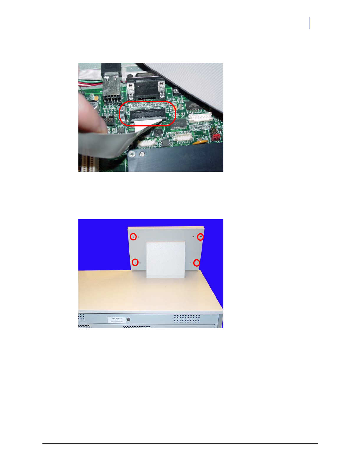
5. Set the lid back down.
6. Remove the four outer screws that secure the LCD bezel to the half cell using a Torx T10
screwdriver.
Figure 1-4. Remove the four outer screws
© 2010 Omnicell, Inc. Half Cell / Supply Mobile Cart Installlation and Service Guide/67-2043 Rev B
Page 8
1-4 Electronics Tray
LCD Assembly
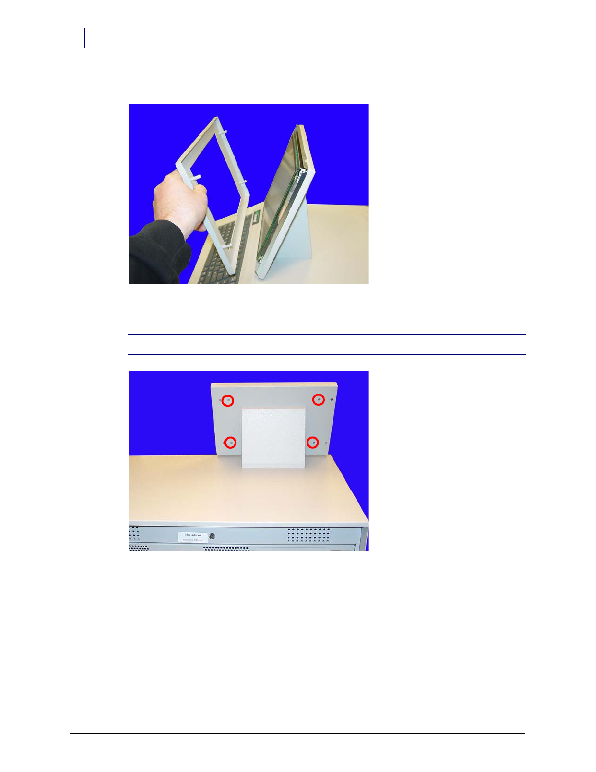
7. Remove the front bezel.
Figure 1-5. Remove the front bezel
8. Remove the four inner screws at the back of the console lid.
Note: Hold onto the front of the LCD screen while removing the screws so that the assembly does not fall.
Figure 1-6. Remove the four inner screws
Half Cell / Supply Mobile Cart Installlation and Service Guide/67-2043 Rev B © 2010 Omnicell, Inc.
Page 9
Electronics Tray 1-5
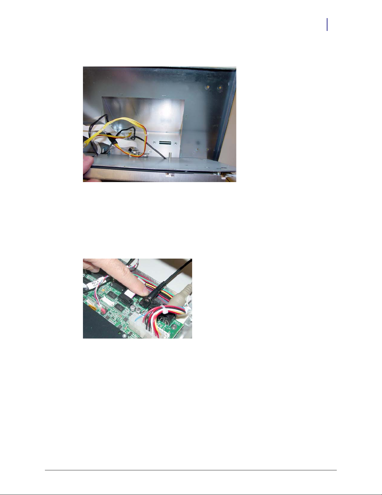
9. Tilt the LCD assembly forward and pull the cables through the opening in the lid.
Figure 1-7. Remove the cables from the opening in the lid
Speaker
Speaker
10. Remove the LCD assembly from the LCD housing.
1. Unlock the lid with key #2036, then open and prop up the lid.
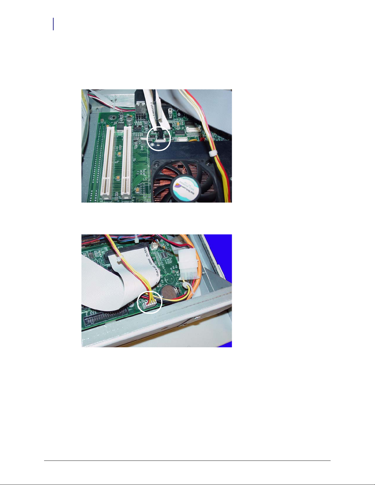
2. Disconnect the speaker cable from the motherboard.
Figure 1-8. Disconnect the speaker cable from the motherboard
© 2010 Omnicell, Inc. Half Cell / Supply Mobile Cart Installlation and Service Guide/67-2043 Rev B
Page 10
1-6 Electronics Tray
Batteries
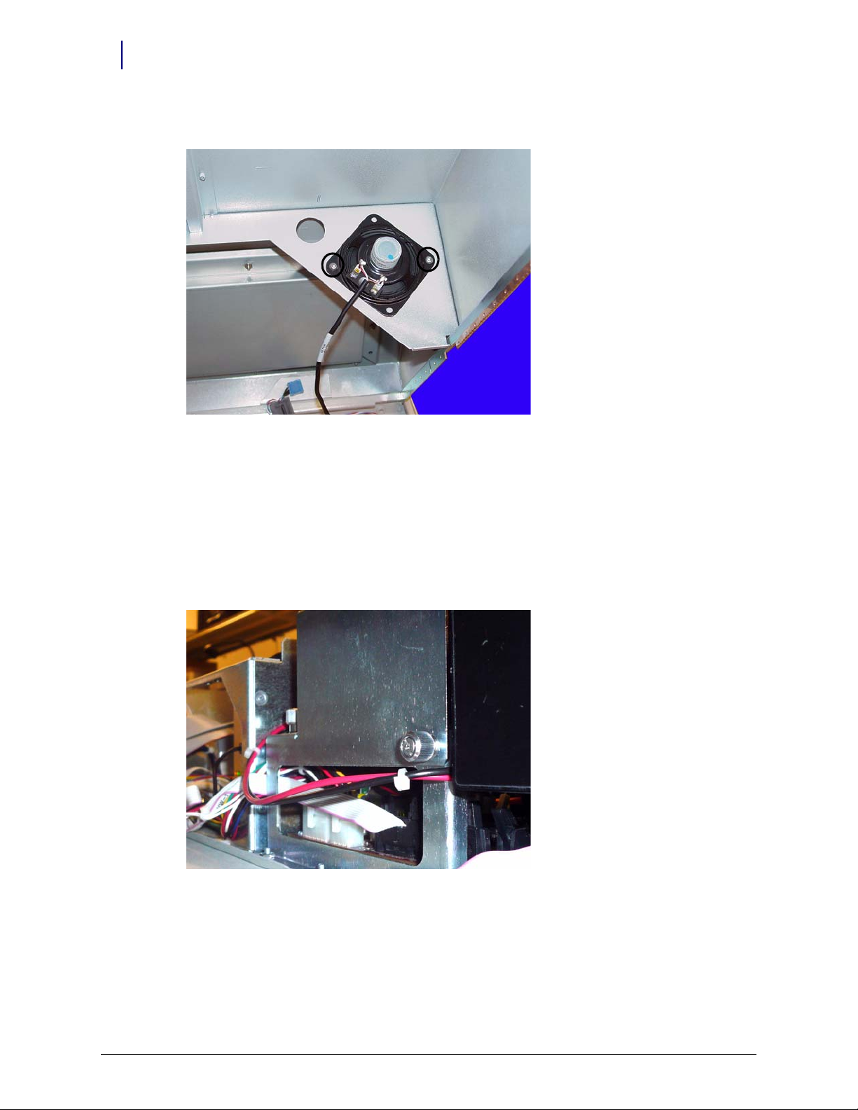
3. Remove the two screws that hold the speaker in place using a Torx T10 screwdriver.
Figure 1-9. Remove the two screws that secure the speaker
Batteries
4. Remove the speaker from the console top.
The supply mobile cart comes with optional batteries.
1. Unlock the lid with key #2036, then open and prop up the lid.
2. Remove the thumb screws that secure the metal cover for the lithium ion batteries.
Figure 1-10. Remove the thumb screws
Half Cell / Supply Mobile Cart Installlation and Service Guide/67-2043 Rev B © 2010 Omnicell, Inc.
Page 11
3. Slide the cover to the left, away from the motherboard.
Figure 1-11. Slide the battery cover
Electronics Tray 1-7
Batteries
4. Lift the cover and remove it from the sled.
Figure 1-12. Lift and remove the battery cover
© 2010 Omnicell, Inc. Half Cell / Supply Mobile Cart Installlation and Service Guide/67-2043 Rev B
Page 12
1-8 Electronics Tray
Batteries
5. Lift the batteries and move them off the stand.
Figure 1-13. Lift the batteries off the stand
6. Disconnect the front battery cable from the motherboard.
Figure 1-14. Disconnect the battery cable
Half Cell / Supply Mobile Cart Installlation and Service Guide/67-2043 Rev B © 2010 Omnicell, Inc.
Page 13
7. Remove the cable from the hole of the battery support frame.
Figure 1-15. Remove the battery cable
Electronics Tray 1-9
Batteries
8. Remove the three screws that secure the battery frame to the sled.
Figure 1-16. Remove the screws that secure the battery frame
9. Remove the battery frame.
a. Lift the frame up and over the screws.
b. Slide the frame toward the front of the sled to remove it.
© 2010 Omnicell, Inc. Half Cell / Supply Mobile Cart Installlation and Service Guide/67-2043 Rev B
Page 14
1-10 Electronics Tray
Printer
Printer
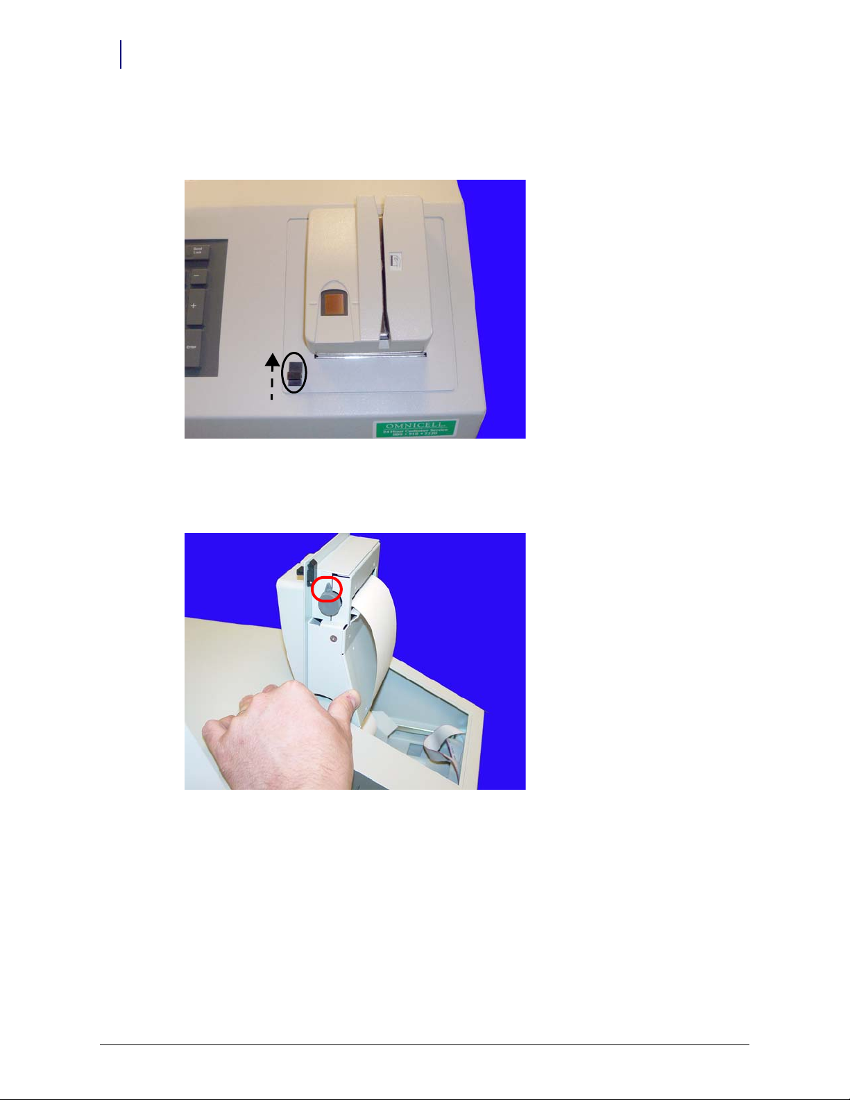
1. Open the printer cover by pushing the black release lever up, then lifting the cover.
Figure 1-17. Open the printer cover
2. Push the platen lever to the left (counter clockwise) to set it to the disengage position.
3. Remove the paper from the printer.
Figure 1-18. Push the platen lever to the left and remove the paper
Half Cell / Supply Mobile Cart Installlation and Service Guide/67-2043 Rev B © 2010 Omnicell, Inc.
Page 15
Electronics Tray 1-11
Printer
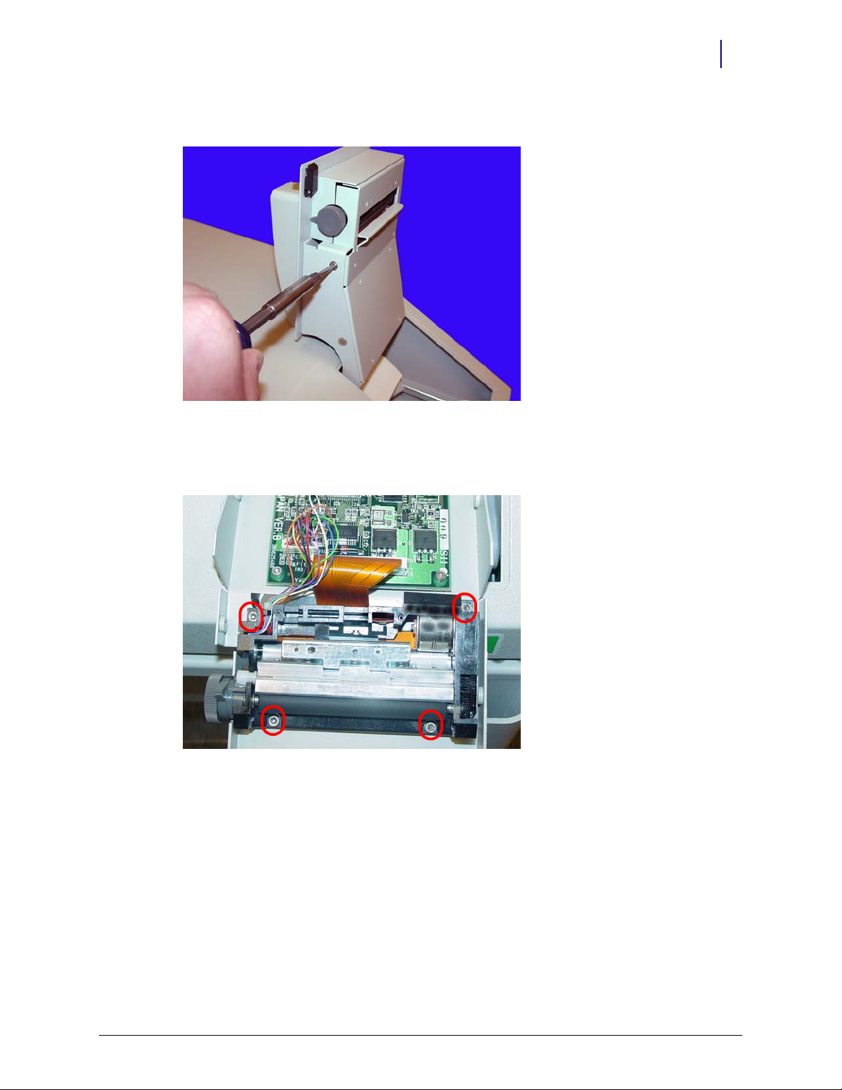
4. Remove the four screws (two on each side) that secure the printer assembly to the cover.
Figure 1-19. Remove the screws securing the printer assembly
5. Remove the printer assembly.
6. Remove the four screws that secure the lower assembly to the frame.
Figure 1-20. Remove the screws that secure the lower assembly
© 2010 Omnicell, Inc. Half Cell / Supply Mobile Cart Installlation and Service Guide/67-2043 Rev B
Page 16
1-12 Electronics Tray
Printer
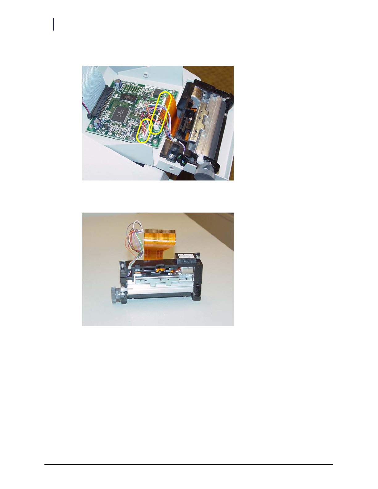
7. Disconnect the printer ribbon cable and the printer data cables from the printer PC Board.
Figure 1-21. Remove the printer ribbon cable and the printer data cable
8. Remove the printer.
Figure 1-22. Remove the printer
Half Cell / Supply Mobile Cart Installlation and Service Guide/67-2043 Rev B © 2010 Omnicell, Inc.
Page 17
9. Remove the four screws that secure the PC card to the frame.
Figure 1-23. Remove the screws that secure the printer PC card
Electronics Tray 1-13
CT PC Tray Upgrade
10. Lift the card off the frame slightly, then remove the printer PC card.
CT PC Tray Upgrade
PowerCom2 Removal
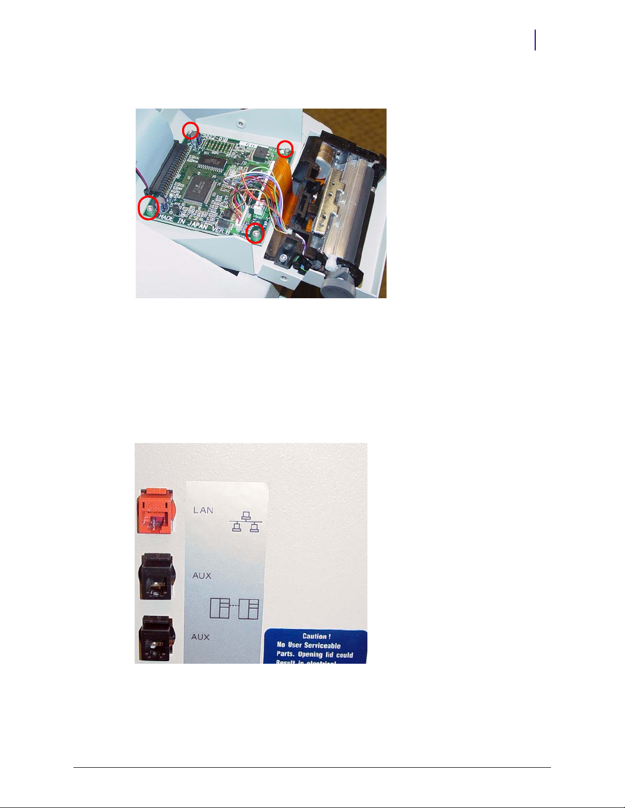
1. Disconnect the LAN cable and the AUX cables from the rear of the CT PC Box.
Figure 1-24. Location and labels for LAN and AUX cable connections on CT PC Tray
2. Unlock the lid with key #2036, then open and prop up the lid.
© 2010 Omnicell, Inc. Half Cell / Supply Mobile Cart Installlation and Service Guide/67-2043 Rev B
Page 18
1-14 Electronics Tray
CT PC Tray Upgrade
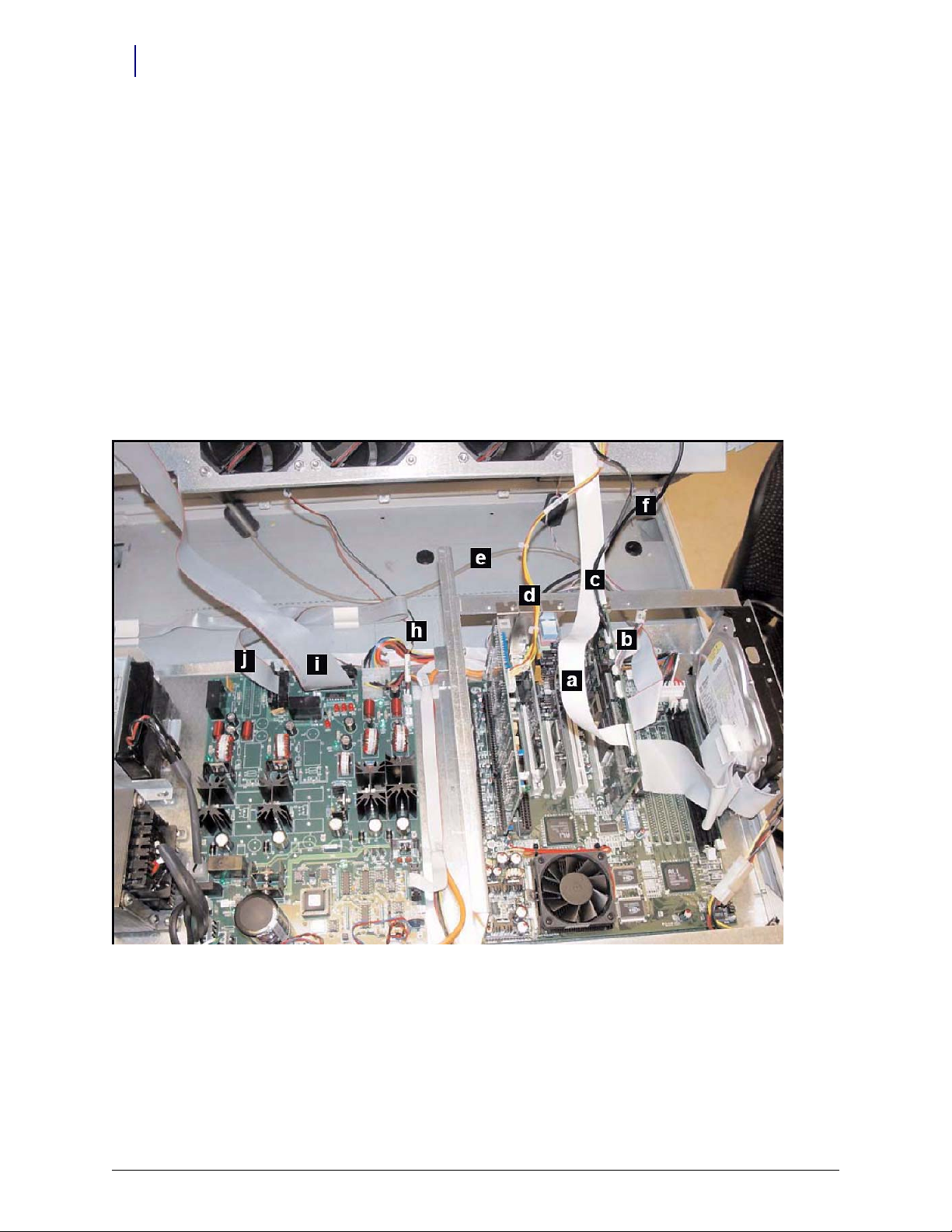
3. Disconnect the following cables from the tray. Match the letters from the list to the ones in
Figure 1-18 for orientation.
a. LCD data cable
b. Contrast cable
c. Inverter (backlight) cable
d. Touch screen data cable
e. Keyboard cable
f. Speaker cable
g. Card reader cable (if applicable–not shown)
h. Fan power cable (if applicable)
i. Printer cable (free cable from any clips)
j. Cabinet power/comm cable
Figure 1-25. Location of cables on the CT PC Tray with PowerCom2 Board
Half Cell / Supply Mobile Cart Installlation and Service Guide/67-2043 Rev B © 2010 Omnicell, Inc.
Page 19
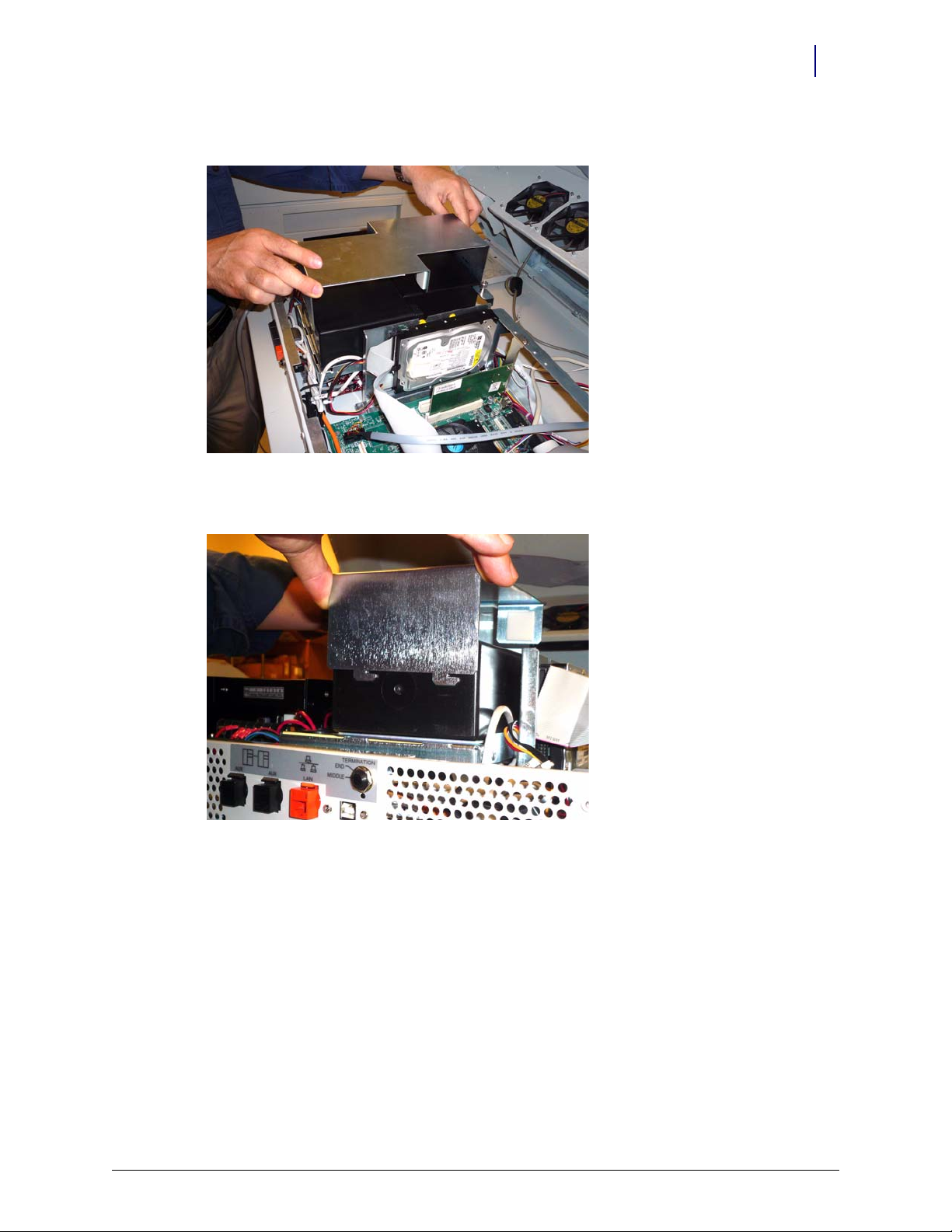
4. Lift and remove the electronics tray.
Electronics Tray 1-15
CT PC Tray Upgrade
Figure 1-26. Lift and remove the CT PC Tray
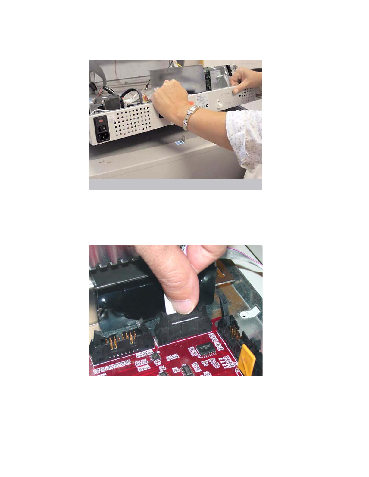
PowerCom3 Installation
1. Place the new electronics tray into the cabinet.
2. Connect the wireway cable (power/comm cable) to the J10 of the PowerCom3 Board
.
Figure 1-27. Connect the Wireway Cable to J10 of the PowerCom3 Board
© 2010 Omnicell, Inc. Half Cell / Supply Mobile Cart Installlation and Service Guide/67-2043 Rev B
Page 20
1-16 Electronics Tray
CT PC Tray Upgrade
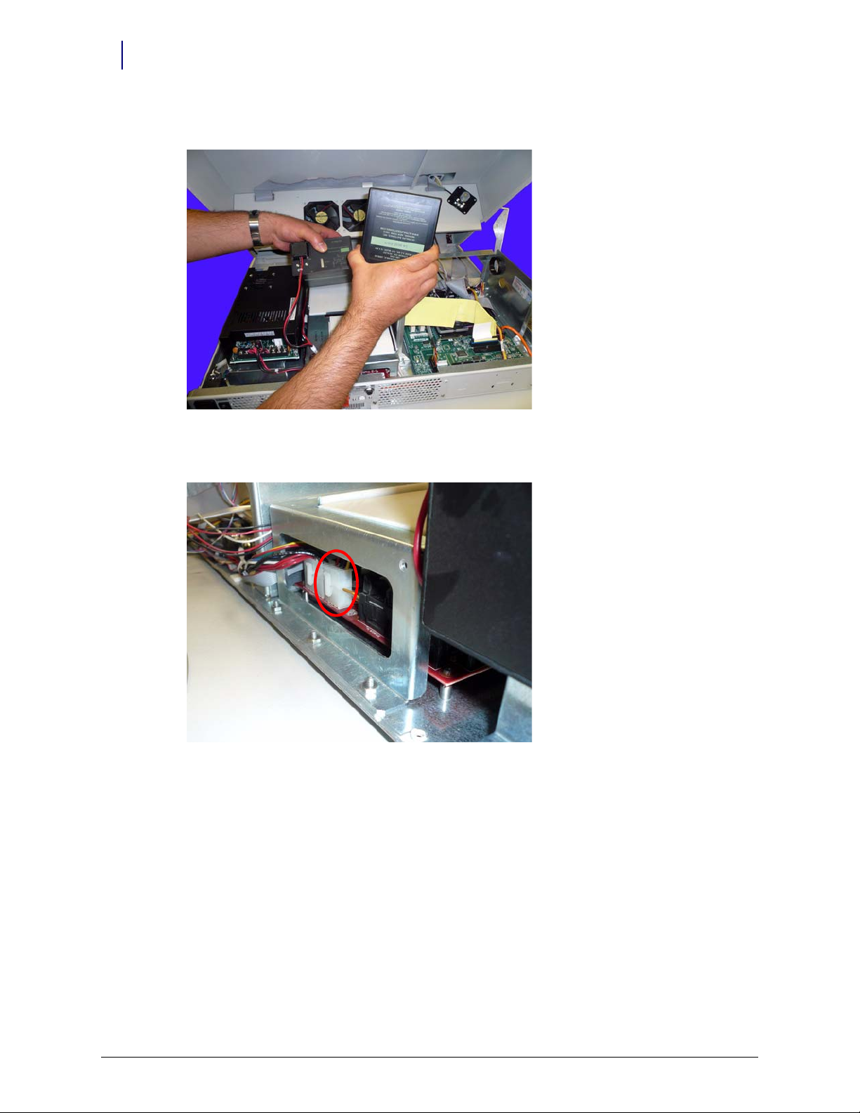
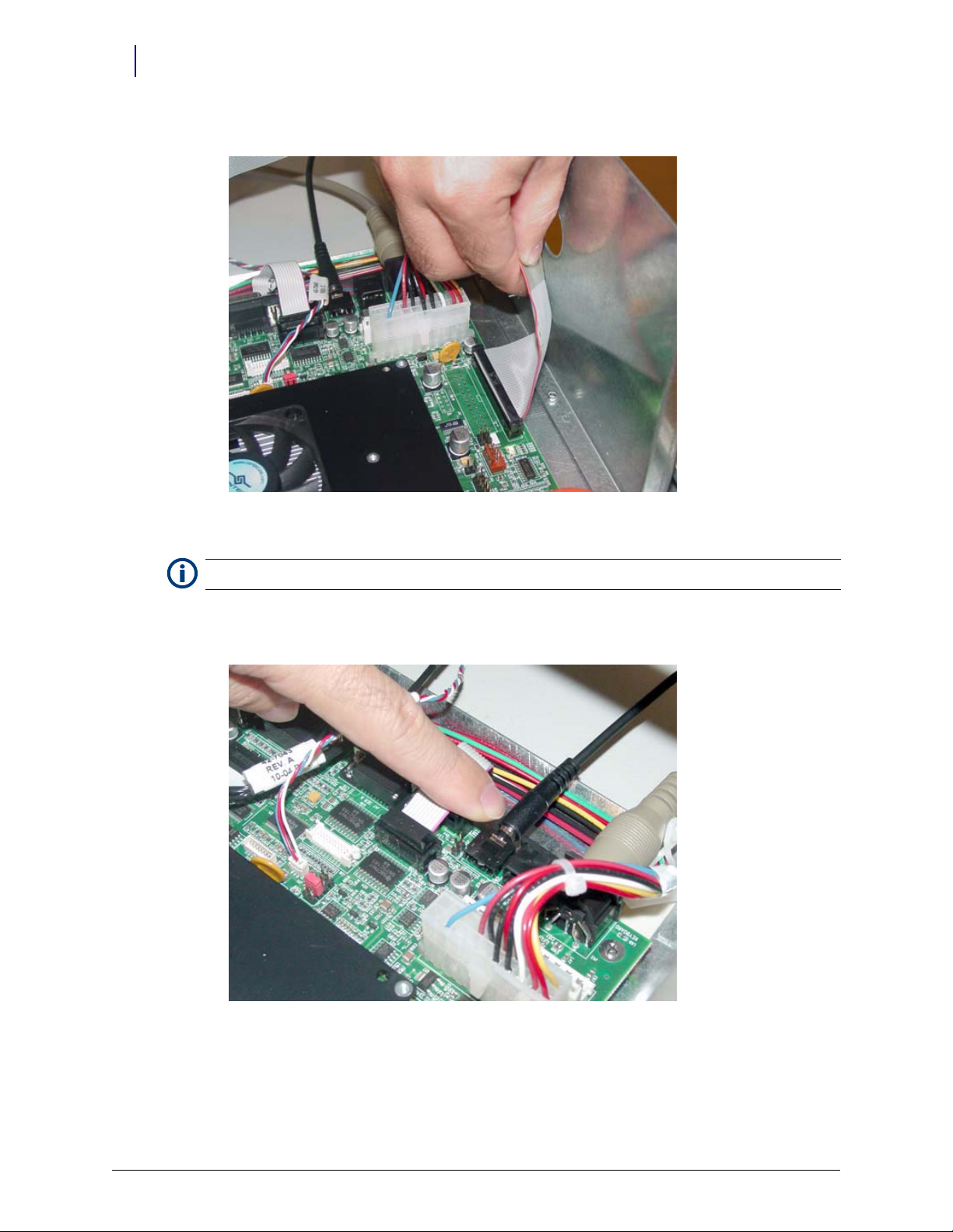
3. Connect the printer cable to J27 on the motherboard.
Figure 1-28. Connect the Printer Cable to J27 of the Motherboard
Note: Ensure that the red wire is connected closest to Pin 1.
4. Connect the fan power cable to J17 on the UPS board (if applicable).
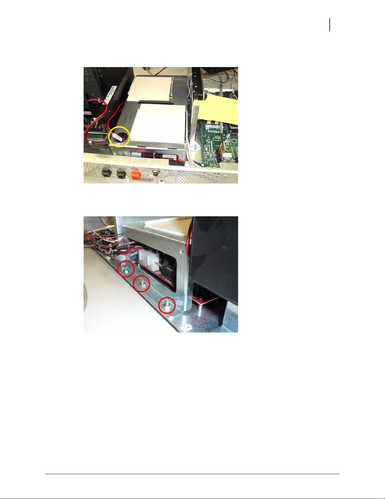
5. Connect the speaker cable to port J45 on the motherboard.
Figure 1-29. Connect the Speaker Cable to J45 of the Motherboard
Half Cell / Supply Mobile Cart Installlation and Service Guide/67-2043 Rev B © 2010 Omnicell, Inc.
Page 21

6. Connect the keyboard cable to port J42 on the motherboard.
Electronics Tray 1-17
CT PC Tray Upgrade
Figure 1-30. Connect the Keyboard Cable to J42 of the Motherboard
7. Connect the touch screen data cable to J2 on the motherboard:
a. Connect the extension cable provided in the kit to the touch screen data cable (red wire to
red wire).
b. Wrap the joined connectors with electrical tape to ensure that the cables do not become
disconnected.
c. Connect the touch screen data cable extension to J2 on the motherboard.
Figure 1-31. Connect the Touch Screen Data Cable to J2 of the Motherboard
© 2010 Omnicell, Inc. Half Cell / Supply Mobile Cart Installlation and Service Guide/67-2043 Rev B
Page 22

1-18 Electronics Tray
CT PC Tray Upgrade
8. Connect the inverter (backlight) cable to J32 on the motherboard.
Figure 1-32. Connect the Backlight Cable to J32 of the Motherboard
9. Connect the contrast cable to J31 on the motherboard.
Figure 1-33. Connect the Contrast Cable to J31 of the Motherboard
Half Cell / Supply Mobile Cart Installlation and Service Guide/67-2043 Rev B © 2010 Omnicell, Inc.
Page 23

10. Connect the LCD data cable to J37 on the motherboard
Electronics Tray 1-19
Standardization Changes
Figure 1-34. Connect the LCD Data Cable to J37 of the Motherboard
11. If a card reader is present and needs to be reconnected:
a. Connect the card reader serial cable to J47 on the motherboard.
b. Connect the card reader power cable to the back of the card reader serial connector.
c. Insert card reader power cable pins into the disk drive power connector.
d. Align the red-stripe pin to the red cable and the gray-stripe pin to the gray cable in next
spot.
Standardization Changes
To standardize the peripherals that Omnicell products use, the Seiko printer and PS/2 keyboards
are being replaced by APS printers and USB keyboards with a numeric pad. The console is
swapped out in this procedure.
1. Lift and prop-up the lid if it is not already open.
2. Disconnect all console cables.
3. Remove the console.
© 2010 Omnicell, Inc. Half Cell / Supply Mobile Cart Installlation and Service Guide/67-2043 Rev B
Page 24

1-20 Electronics Tray
System Restart
4. Replace the cable cover bracket with the new, wider one using three screws.
Figure 1-35. Cable cover bracket
5. Place new console into position, then prop it open.
6. Re-connect the cables. Most will go back where the old cables were with a couple of exceptions.
The contrast cable goes into J33 instead of J32.
The USB keyboard cable goes to the USB port (vs. the PS/2 connection).
Move the jumper on JP1 from pins 1-2 to 3-4.
System Restart
Perform the following steps after parts (or the sled) have been replaced.
1. Close and lock the lid.
2. Plug the cabinet power cord into the proper outlet.
3. Reboot the system.
Half Cell / Supply Mobile Cart Installlation and Service Guide/67-2043 Rev B © 2010 Omnicell, Inc.
Page 25

Frames and Wireways
Introduction
The half-cell/supply mobile cart cabinet has a metal frame which houses the SPC boards. Many of
the cables connect the components of the system. The frame is not field repairable and must be
replaced if it is damaged. The wireway on the right side of any cabinet in a half-cell/supply mobile
cart is removable. The SPC boards contained on the wireways are also replaceable.
Perform the shutdown procedures before starting any service. Replace the wireway by generally
performing the removal procedure in reverse. Perform the restart steps after the wireway has been
serviced.
Tools List
The following tools are required to perform the procedures in this chapter:
Frames and Wireways 2-1
Introduction
Torx T15 driver
Torx T25 driver
Shutdown Procedures
1. Perform a graceful shutdown of the system.
2. Unplug the cabinet from its power source.
Wireway Removal
1. Remove any manual override covers, if applicable.
2. Remove any modules that are attached to the wireway.
© 2010 Omnicell, Inc. Half Cell / Supply Mobile Cart Installlation and Service Guide/67-2043 Rev B
Page 26

2-2 Frames and Wireways
Wireway Removal
3. Remove the four screws on the right side of the half cell that secure the wireway to the frame
using a Torx T15 screwdriver.
Figure 2-1. Remove the four screws on the side of the half cell
Half Cell / Supply Mobile Cart Installlation and Service Guide/67-2043 Rev B © 2010 Omnicell, Inc.
Page 27

Frames and Wireways 2-3
Wireway Removal
4. Remove the two screws on the front of the half cell that secure the wireway to the frame using
a Torx T15 screwdriver.
Figure 2-2. Remove the two screws on the front of the half cell
© 2010 Omnicell, Inc. Half Cell / Supply Mobile Cart Installlation and Service Guide/67-2043 Rev B
Page 28

2-4 Frames and Wireways
Wireway Removal
5. Remove the screws on either side of the transport handle using a Torx T25 screwdriver.
Figure 2-3. Remove the two screws securing the transport handle
6. Push the transport handle toward the rear of the half cell then remove it from the frame.
Half Cell / Supply Mobile Cart Installlation and Service Guide/67-2043 Rev B © 2010 Omnicell, Inc.
Page 29

Frames and Wireways 2-5
System Restart
7. Pull the wireway backward toward the rear of the frame and disconnect the ribbon cable
(drawer connect board to IUPS cable assembly).
Figure 2-4. Disconnect the ribbon cable and remove the wireway
8. Remove the wireway.
System Restart
Perform the following steps after the wireway has been replaced.
1. Plug the cabinet power cord into the proper outlet.
2. Reboot the system.
© 2010 Omnicell, Inc. Half Cell / Supply Mobile Cart Installlation and Service Guide/67-2043 Rev B
Page 30

2-6 Frames and Wireways
System Restart
Half Cell / Supply Mobile Cart Installlation and Service Guide/67-2043 Rev B © 2010 Omnicell, Inc.
Page 31

Shelves
Introduction
Shelves can be moved or removed as needed. The cabinet must be powered down to safely handle
the switchpanels and cables. If only the dividers are to be moved/removed, the cabinet does not
need to be powered down. Perform the restart steps if the cabinet was powered down for service.
A Torx T15 screwdriver is the only tool required to remove/install shelves.
Shutdown Procedures
1. Perform a graceful shutdown of the system.
2. Unplug the cabinet from its power source.
Shelves 3-1
Introduction
Shelf Removal
1. Open the door, then remove any remaining items from the shelf.
2. Lift the shelf clips to the open position on either side of the switchpanel.
Figure 3-1. Lift the shelf clips
3. Pull the switchpanel holder out a little to access the switchpanel cable.
o
© 2010 Omnicell, Inc. Half Cell / Supply Mobile Cart Installlation and Service Guide/67-2043 Rev B
Page 32

3-2 Shelves
Shelf Removal
4. Disconnect the switchpanel cable from the SPC board in the wireway.
Figure 3-2. Disconnect the switchpanel from the SPC board
5. Slide the switchpanel out from its holder.
Figure 3-3. Remove the switchpanel from its holder
Half Cell / Supply Mobile Cart Installlation and Service Guide/67-2043 Rev B © 2010 Omnicell, Inc.
Page 33

6. Push the shelf up from the slots in the shelf clips and remove the shelf.
Figure 3-4. Push the shelf up and remove
Shelves 3-3
Shelf Removal
7. If installing a new shelf, go to step 3 of “Shelf Installation” on page 3-4
8. If a new shelf will not be re-installed in the same location, perform the following steps.
a. Remove the shelf clips.
Note:
In certain cases, the shelf clip may be secured with a single screw that provides extra support. Remove
the screw using a Torx T15 screwdriver.
b. Install switchpanel connector covers where the shelf clips were removed.
© 2010 Omnicell, Inc. Half Cell / Supply Mobile Cart Installlation and Service Guide/67-2043 Rev B
Page 34

3-4 Shelves
Divider Removal
Divider Removal
1. Open the door, then remove items from the shelf to access the dividers.
2. Remove the dividers from their clips.
3. Rotate the divider clips 90 degrees to unlock from the shelf bars, then remove them.
Figure 3-5. Remove the clip from the shelf
Shelf Installation
1. Remove the switchpanel connector cover where the shelf will be installed.
2. Insert right and left shelf clips into the exposed frame holes.
3. Slide the switchpanel into its holder.
Figure 3-6. Slide the switchpanel into its holder
4. Lift up the tabs on the shelf clips.
Half Cell / Supply Mobile Cart Installlation and Service Guide/67-2043 Rev B © 2010 Omnicell, Inc.
Page 35

5. Connect the switchpanel cable to the SPC board in the wireway.
Figure 3-7. Connect the Switchpanel to the SPC Board
Shelves 3-5
Shelf Installation
6. Insert the switchpanel holder into the shelf clips and close the clips.
7. Slide the shelf into the mounting slots at the back of the frame.
8. Lower the shelf into the shelf supports and ensure they are locked into place.
9. Stock the shelf as needed, then close the cabinet door.
© 2010 Omnicell, Inc. Half Cell / Supply Mobile Cart Installlation and Service Guide/67-2043 Rev B
Page 36

3-6 Shelves
Divider Installation
Divider Installation
1. Place the clips on the shelf at the desired position.
2. Rotate the clips 90 degrees and lock them into place on the shelf.
Figure 3-8. Rotate the Shelf Clip and Lock it Into Place
3. Slide the dividers into the clips.
4. Stock the shelf as needed, then close the cabinet door.
Pull-out Shelf Installation
A pull-out shelf is designed to increase the accessibility of items located at the rear of a cabinet
shelf. The shelf is mounted on rails and can be pulled out from the cabinet. The pull-out shelf is a
product option that must be purchased separately and does not come as a standard feature.
1. Open the cabinet door.
2. If replacing a standard shelf, do the following steps:
a. Remove items from the shelf.
b. Remove the standard shelf. Refer to “Shelf Removal” on page 3-1.
3. Insert the pull-out shelf into the frame.
Make sure that the tabs on the back of the assembly slide completely into the slots on the back
of the frame.
4. Insert mounting screws (one on each side) using a Torx T15 screwdriver.
5. Connect the switchpanel cable to the wireway.
6. Replace the connector covers.
To remove the pull-out shelf, generally perform the installation steps in reverse.
Half Cell / Supply Mobile Cart Installlation and Service Guide/67-2043 Rev B © 2010 Omnicell, Inc.
Page 37

System Restart
Perform the following steps after the shelves have been replaced.
1. Plug the cabinet power cord into the proper outlet.
2. Reboot the system.
Shelves 3-7
System Restart
© 2010 Omnicell, Inc. Half Cell / Supply Mobile Cart Installlation and Service Guide/67-2043 Rev B
Page 38

3-8 Shelves
System Restart
Half Cell / Supply Mobile Cart Installlation and Service Guide/67-2043 Rev B © 2010 Omnicell, Inc.
Page 39

Switchpanels
Introduction
There are two types of switchpanels. One type is used with shelves (standard/pull-out), The other
type is used with a supply drawer. Switchpanels are used to identify specific items in the cabinet.
When a user selects an item from the screen display, the proper switchpanel LEDs light up to
indicate product location.
Switchpanels can be removed (and relocated) with its corresponding drawer or shelf. They can be
switched from shelf to shelf or drawer to drawer. However, switchpanel types cannot be mixed
between a shelf and a drawer.
The cabinet must be shut down to safely remove switchpanels and their cables. Switchpanels are
replaced by generally performing the removal procedures in reverse. See “Shelf Installation” on
page 3-4. Perform the restart steps after the service is completed.
Switchpanels 4-1
Introduction
Tools List
The following tools are required to remove or install a switchpanel:
Torx T15 screwdriver
Tor x T8 sc r ew d ri v er
Needle-nosed pliers
1/4” nut driver
5/64” Allen wrench
3/32” Allen wrench
Phillips head screwdriver
5/16” nut driver
Shutdown Procedures
1. Perform a graceful shutdown of the system.
2. Unplug the cabinet from its power source.
© 2010 Omnicell, Inc. Half Cell / Supply Mobile Cart Installlation and Service Guide/67-2043 Rev B
Page 40

4-2 Switchpanels
Switchpanel Removal
Switchpanel Removal
Shelf Switchpanel
1. Open the cabinet door to access the switchpanel.
2. Lift the shelf clips to the open position on either side of the switchpanel.
o
Figure 4-1. Lift the Shelf Clips
3. Disconnect the switchpanel cable from the SPC board in the wireway.r
4. Remove the switchpanel holder.
5. Slide the switchpanel out of its holder.
Figure 4-2. Remove the switchpanel from its holder
Half Cell / Supply Mobile Cart Installlation and Service Guide/67-2043 Rev B © 2010 Omnicell, Inc.
Page 41

Supply Drawer Switchpanel
1. Empty items from the drawer.
2. Disconnect the drawer module from the wireway.
Switchpanels 4-3
Switchpanel Removal
Figure 4-3. Disconnect the Switchpanel from the SPC Board in the Wireway
3. Open the drawer.
4. Use a 1/4 nut driver to remove the four nuts holding the switchpanel in place.
5. Unplug the switchpanel cable from the drawer switchpanel control board.
6. Remove the two screws on the bottom of the supply drawer using a T15 Torx screwdriver.
Figure 4-4. Remove the screws securing the drawer to the mounting bracket
7. Remove the supply drawer from the cabinet.
8. Turn the supply drawer upside down and open it.
9. Disconnect the switchpanel cable.
10. Remove the four nuts located on the drawer using a 1/4” nut driver.
© 2010 Omnicell, Inc. Half Cell / Supply Mobile Cart Installlation and Service Guide/67-2043 Rev B
Page 42

4-4 Switchpanels
System Restart
11. Remove the switchpanel.
Figure 4-5. Remove the Switchpanel from the Drawer
Pull-out Shelf Switchpanel
1. Slide the shelf partially out of the dispenser unit.
2. Remove the four screws from the top of the switchpanel using a 5/64” Allen wrench.
.
Note: The switchpanel is still connected to the shelf. Do not try to forcibly remove the switchpanel.
3. Pull the left side of the switchpanel away from the shelf to expose the two screws securing the
switchpanel to the right side of the frame.
4. Remove the two screws using a small Phillips head screwdriver.
5. Remove the switchpanel cable from the wireway cable.
6. Remove the switchpanel.
System Restart
Perform the following steps after the switchpanel(s) have been replaced.
1. Plug the cabinet power cord into the proper outlet.
2. Reboot the system.
Half Cell / Supply Mobile Cart Installlation and Service Guide/67-2043 Rev B © 2010 Omnicell, Inc.
Page 43

Doors
Introduction
Half-cell cabinets may or may not have a door, depending on the configuration of the cabinet.
Tools List
The following tools are required to install/replace doors on a half cell:
Torx T15 screwdriver
Torx T20 screwdriver
#2036 key
Door Removal
Doors 5-1
Introduction
1. Open the door.
If the cabinet is powered up, enter an administrator user name and password into the
system.
If the cabinet is not powered up, unlock the cabinet door using the #2036 key.
2. Remove the two screws securing the top bracket of the door using a T20 Torx screwdriver.
© 2010 Omnicell, Inc. Half Cell / Supply Mobile Cart Installlation and Service Guide/67-2043 Rev B
Page 44

5-2 Doors
Door Installation
Note:
Hold onto the door while removing the two screws. Otherwise, the door may fall and be damaged after
the screws are removed.
Figure 5-1. Remove the screws securing the top bracket
3. Lift the door off the lower door bracket.
Door Installation
Half Cell Door
1. Place the door, bottom first, onto the bottom bracket. Ensure that the door is securely placed
in the bracket.
2. Place the top bracket onto the door and line up the top of the door with the screw holes on the
cabinet frame.
3. Attach the two screws securing the top bracket to the frame.
One-Third Door
1. Place the door, bottom first, onto the bottom bracket. Ensure that the door is securely placed
in the bracket.
2. Line up the door with the screw holes on the top bracket.
3. Attach the two screws securing the door to the top bracket.
Half Cell / Supply Mobile Cart Installlation and Service Guide/67-2043 Rev B © 2010 Omnicell, Inc.
Page 45

Drawers
Introduction
There are two types of drawers, one for pharmacy and one for supplies. Each type has multiple
modules for varying degrees of security.
Supply Drawers
Supply drawers are used to store items that are frequently used and require little security. The
available models are:
Drawers 6-1
Introduction
Omnicell Matrix Drawer (OMD) is a drawer without lids. Drawer space is configured into a
matrix of storage areas with dividers and drawer liners. The maximum number of storage areas
(or bins) is 96.
Omnicell Lighted Matrix Drawer (OLMD) is similar to the drawer above, but with guiding
light technology. LEDs are used to direct users to the proper supplies location. The lit matrix
drawer can be configurable for up to 24 bins.
Pharmacy Drawers
Pharmacy drawers have more security. They are designed to store low security medications or
high security narcotics. The available modules are:
Omnicell Sensing Lid (OSL) is used for low security medications. As each lid is lifted, the
system senses and records access to the bin. This guarantees security to those drawers that
contain controlled substances.
Omnicell Locking Lid (OLL) has the highest security for storing narcotics. When these high
security drawers are opened, the user can only access the one bin containing the pre-selected
medication. No other bin is unlocked when the user is working in the desired bin. Special
censors provide audible and visual feedback if users attempt unauthorized entry into bins that
are not pre-selected.
Tools List
The following tools may be required to install a drawer:
Torx T10 screwdriver
Torx T15 screwdriver
Double-sided tape
© 2010 Omnicell, Inc. Half Cell / Supply Mobile Cart Installlation and Service Guide/67-2043 Rev B
Page 46

6-2 Drawers
Bin Configuration
Bin Configuration
Unlit Matrix Drawers
Each unlit matrix drawer can contain a maximum of 96 bins - 24 in each quadrant. Customers can
utilize the flexibility of this drawer and custom-configure it to meet specific needs and
requirements for the site. As with other matrix drawers, the dividers are designed to be snapped
off, enabling the bins to be custom-configured to fit site-specific needs.
Figure 6-1. Matrix drawer dividers
Dividers must be placed into the drawer in a specific order with each divider in a specific slot, so
Note:
separating the dividers by part number is recommended.
1. Before installing the dividers, ensure that the layout of each drawer has been approved by the
customer.
Note: It is recommended that a drawing be made of each drawer, showing the customer’s preferred
configuration for each quadrant of a given drawer.
2. Break the divider tabs according to the customer design and trim away excess plastic to ensure
a snug fit in the drawer.
3. Add the dividers to the bin liner. The dividers should snap into the bottom of the drawer and
the sides of each bin liner quadrant.
4. Use the gray circular labels provided with the kit to cover any un-used divider slots in the bin
liner.
Half Cell / Supply Mobile Cart Installlation and Service Guide/67-2043 Rev B © 2010 Omnicell, Inc.
Page 47

Lit Matrix Drawers
Each lit matrix drawer can contain a maximum of 24 bins - six in each quadrant. Customers can
utilize the flexibility of this drawer and custom-configure it to meet specific needs and
requirements for the site. As with other matrix drawers, the dividers are designed to be snapped
off, enabling the bins to be custom-configured to fit site-specific needs.
Note:
separating the dividers by part number is recommended.
Drawers 6-3
Bin Configuration
Dividers must be placed into the drawer in a specific order with each divider in a specific slot, so
Figure 6-2. Lit matrix drawer
1. Before installing the dividers, ensure that the layout of each drawer has been approved by the
customer.
Note: It is recommended that a drawing be made of each drawer, showing the customer’s preferred
configuration for each quadrant of a given drawer.
2. Break the divider tabs according to the customer design and trim away excess plastic to ensure
a snug fit in the drawer.
3. Add the dividers to the bin liner. The dividers should snap into the bottom of the drawer and
the sides of each bin liner quadrant.
4. Use the gray circular labels provided with the kit to cover any un-used divider slots in the bin
liner.
5. Insert the light pipes into each notch provided in the dividers. The light pipe is installed on the
rear side of the bin divider and snaps into a slot on the bottom of the bin liner.
Note: Be sure to place a light pipe into every notch, even if the position will not be used for guiding light
purposes. The pipes provide support and help keep the dividers in place.
© 2010 Omnicell, Inc. Half Cell / Supply Mobile Cart Installlation and Service Guide/67-2043 Rev B
Page 48

6-4 Drawers
Bin Configuration
Matrix Drawers Labels
Numerical bin labels are provided with matrix drawers to make bin identification and restock
easier for the customer.
The bottom of the bin liner on any matrix drawer is numbered according to its type (i.e. 1-96, 124, 1-4). These numbers are used to identify bin locations for the drawer. The drawer will be
numbered by using the lowest number in a specific bin. Using Figure 6-3 as an example, the bin in
the lower right corner of the drawer would be Bin 7, the bin in the upper left corner would be Bin
49, and the bin in the upper right corner would be Bin 85.
Figure 6-3. Matrix drawer labelling system
Once a bin has been configured, label the bin divider to correspond with the bin name corner and
affix the label to the top of the right rear divider of that bin.
Half Cell / Supply Mobile Cart Installlation and Service Guide/67-2043 Rev B © 2010 Omnicell, Inc.
Page 49

Installation
Perform the shutdown procedure before servicing any drawers. Remove supply and double-deep
drawers by generally performing the installation steps in reverse. After the service is complete,
follow the restart steps.
Shutdown Procedure
1. Perform a graceful shutdown of the system.
2. Unplug the cabinet from its power source.
Double-Deep Matrix Drawer
1. Clear the space for the new drawer by removing one of the following:
the existing double deep drawer
the two existing single drawers
the two false drawer fronts
a false drawer front and a single drawer
See “Pharmacy Drawer Removal” on page 6-8 if needed.
Drawers 6-5
Installation
Note:
inside the carrier before continuing.
2. Insert the bin liner into the drawer with the side numbered 1 and 2 facing the front.
3. Insert the right/left bin divider into the bin liner.
4. Insert the front/rear bin divider into the bin liner.
5. Connect the drawer cable.
6. Insert the drawer into the carrier.
Supply Drawer
1. Open the door in the zone where the supply drawer will be located.
2. Slide the two drawer brackets into the slots in the back of the frame.
3. Secure the bracket to the frame with the screw provided using a Torx T15 screwdriver.
4. Slide the supply drawer and housing onto the brackets until the drawer snaps into the latching
5. Connect the SPC board cable to the 10-pin connector on the SPC board in the wireway.
6. Insert two screws one on either side of the bottom of the drawer.
7. Use a Torx T15 screwdriver to secure the supply drawer to the drawer brackets.
8. Insert the switchpanel connector cover into the hole in the frame.
9. Set the DIP switches for the shelf and the zone settings. There are two DIP switches: The first
If two single deep drawers are removed, the lower set of slide mount brackets must be removed from
tabs located on the back of the bracket.
DIP switch (S1) sets the drawer zone. The second DIP switch (S2)sets the drawer location.
Note: On switch S1, switch #8 must always be off for a supply drawer.
© 2010 Omnicell, Inc. Half Cell / Supply Mobile Cart Installlation and Service Guide/67-2043 Rev B
Page 50

6-6 Drawers
Installation
Pharmacy Drawer
Important:
A Pharmacist must be present when servicing drawers where medications are present.
1. Unlock the manual override cover using keys #2302, 2232.
2. Remove the cover by pushing it to the right and lifting it off.
3. Remove any false drawer fronts by removing the two screws that secure the false drawer front
with a Torx T15 screwdriver.
Note: Keep the screws securing the false drawer front. They will be used later in the procedure.
Figure 6-4. Remove the screws securing the false drawer front
4. Remove the slide mounting bracket.
Figure 6-5. Remove the slide support bracket
5. Connect the drawer cable to the drawer connect board.
Half Cell / Supply Mobile Cart Installlation and Service Guide/67-2043 Rev B © 2010 Omnicell, Inc.
Page 51

Drawers 6-7
Installation
6. Attach one side of the double-sided tape to the cable clamp and the other to the drawer cable.
7. Line up the tape to the edges of the clamp and secure the clamp to the carrier with two screws
using a Torx T15 screwdriver.
8. Connect the drawer controller cable to the drawer controller board at the rear end of the
drawer.
9. Secure the slide to the slide mounting bracket with three screws and washers using a Torx T15
screwdriver.
10. Install the slide support bracket with slide attached.
11. Connect a slide to the left side of the carrier using the three screws provided. Tighten the
screws using a Torx T15 screwdriver.
Figure 6-6. Install the new slide support bracket
Note:
The washers must be used. They ensure that the screw threads do not protrude into the cable path.
12. Place the drawer controller cable between the two ends of the drawer controller cable clamp.
13. Secure the pharmacy drawer controller cable clamp and the drawer controller cable to the
pharmacy drawer with two screws using a Torx T10 screwdriver.
14. Close the drawer and replace the pharmacy manual override cover.
© 2010 Omnicell, Inc. Half Cell / Supply Mobile Cart Installlation and Service Guide/67-2043 Rev B
Page 52

6-8 Drawers
Pharmacy Drawer Removal
Pharmacy Drawer Removal
1. Remove the manual override cover on the pharmacy drawers.
Figure 6-7. Remove the manual override cover
2. Pull the manual override lever and open the desired pharmacy drawer.
3. Remove the two screws securing the drawer controller cable cover to the cable clamps using a
Torx T10 screwdriver.
Figure 6-8. Remove the controller cable cover
Half Cell / Supply Mobile Cart Installlation and Service Guide/67-2043 Rev B © 2010 Omnicell, Inc.
Page 53

4. Remove the cable clamp and disconnect the cable.
Figure 6-9. Remove the controller cable
Drawers 6-9
System Restart
5. Push the release levers on either side of the drawer up or down to release the drawer.
Figure 6-10. Push the release levers to release the drawer
6. Remove the pharmacy drawer from the module.
System Restart
1. Plug the cabinet power cord into the proper outlet.
2. Reboot the system.
3. Program the pharmacy drawer in Omni Configurations.
© 2010 Omnicell, Inc. Half Cell / Supply Mobile Cart Installlation and Service Guide/67-2043 Rev B
Page 54

6-10 Drawers
System Restart
Half Cell / Supply Mobile Cart Installlation and Service Guide/67-2043 Rev B © 2010 Omnicell, Inc.
Page 55

Appendix A: Part List
Link back to the procedure that calls out the given part using the cross reference in the Where Used
column.
Part # Part Name Agile Description Where Used
11-4101
11-4128
12-3102
12-3113
13-1129
13-1142
13-1136
13-1143
13-1150
13-1152
13-1151
13-1153
13-3109 pull-out shelf ASSY,PULL-OUT SHELF
14-1123
14-1291
14-1261 LCD assembly MFG ASSY, DISPLAY,ETX-REVC,LVDS,RX-CT
14-2040
13-1128-58
14-7008
14-7009
14-7013
14-7015
14-7016
14-7021 double-deep matrix drawer
door; \1/3 door;
half cell door
supply drawer (single drawer); DRAWER ASSY,SUPPLY,OSD24,GREEN BUTTONS
lid, console MFG ASSY, LID, ETX, LVDS, RX-CT (old)
printer, printer assembly MFG,ASSY,PRINTER,OMNIRX (old)
electronics tray ELECTRONICS TRAY,ETX2,5.10.1.9,ANESTHESIA (PowerCom3)
pharmacy drawer MODEL,OLL6,LARGE,LOCKING DRAWER,RX2
bin labels [comes with drawer]
MFG,ASSY,DOOR,1/3,OMNI,1
MFG,ASSY,DOOR,HALF-CELL REDESIGN
DRAWER ASSY,SUPPLY,OSD24,BLUE BUTTONS
MFG ASSY, LID, LVDS, RX-CT, MOBILE CART (old)
MFG ASSY,LID W/O PTR,CE (old)
MFG ASSY, LID W/O PTR, MOBILE CART (old)
MFG ASSY, LID, ETX, LVDS, RX-CT (new)
MFG ASSY, LID, LVDS, RX-CT, MOBILE CART (new)
MFG ASSY,LID W/O APS PTR,CE (new)
MFG ASSY, LID W/O APS PTR, MOBILE CART (new)
MFG ASSY,APS PRINTER,OMNIRX (new)
MFG ASSY,CT PC BOX,W/PTR, 5.8 XP ETX CE (PowerCom2) [inactive]
MODEL,OSL6,LARGE,SENSING DRAWER,RX2
MODEL,OSL12,REGULAR,SENSING DRAWER,RX2
MODEL,OSL24,24-BIN,SENSING DRAWER,RX2
MODEL,OLMD24,24-LIT,MATRIX MATRIX,DRAWER
MODEL OMD4,4-BIN MATRIX DRAWER,UNLIT
Door Installation
Door Removal
Double-Deep
Matrix Drawer
Supply Drawer
Supply Drawer
Switchpanel
Standardization
Changes
Pull-out Shelf
Installation
Printer
LCD Assembly
PowerCom2
Removal
PowerCom3
Installation
Pharmacy Drawer
Double-Deep
Matrix Drawer
Matrix Drawers
Labels
A-1
Table A-1. OmniRx Part List
© 2010 Omnicell, Inc. Half Cell / Supply Mobile Cart Installlation and Service Guide/67-2043 Rev B
Page 56

A-2 Appendix A: Part List
Part # Part Name Agile Description Where Used
15-7020 false drawer front MFG,ASSY,DRAWER,FRONT,DUMMY RX2
Double-Deep
Matrix Drawer
Pharmacy Drawer
15-7075
15-7076
divider (kit)
w/gray labels
KIT,DIVIDER,24-BIN,LIT,MATRIX
KIT,DIVIDER,4/96,BIN,UNLIT,MTR
Lit Matrix Drawers
Unlit Matrix
Drawers
40-1045
71-7008
40-7035 wireway cable PCB ASSY,RX,DRAWER,CONNECT OMNIRX
PC card PCBA, PRINTER INTERFACE, APS
PCB ASSY,PRINTER,RIGHT ANGLE SHROUDED CONN (Seiko)
Printer
PowerCom3
Installation
41-7009 (wireway) SPC Board
drawer controller board
42-1157 thumb screw (part of assy)
battery cover (part of assy)
battery (part of assy)
battery cable (part of assy)
battery frame (part of assy)
battery frame screw (in assy)
42-1185 cabinet power cable CABLE,ASSY,POWER,SWITCH
PCB,RX,DRAWER,CONNECT RX
CABLE,ASSY,BATTERY,OMNIXPRESS
Pharmacy Drawer
Wire w ay R e mov a l
Batteries
PowerCom2
Removal
42-1204 card reader cable CABLE,ASSY,POWER,CARD,READER CT,PC,BOX
PowerCom2
Removal
42-1210 fan cable CABLE,ASSY,FAN RETROFIT COOLING,OMNIRX
PowerCom2
Removal
42-1229 video image cable, LCD data
cable
CABLE ASSY, LVDS LCD DISPLAY
LCD Assembly
PowerCom2
Removal
42-1302-02 [USB keyboard] power cable CABLE,ASSY,USB KEYBOARD,QWERTY TO MOTHERBOARD,STD,CTPC
Standardization
Changes
42-1304 (printer) power cable CABLE ASSY, POWER, APS PTR, CT PC BOX
PowerCom2
Removal
42-1307 [keypad/keyboard] ribbon cable CABLE ASSY,NUMERIC TO KEYBD, OMNIRX/TT
PowerCom2
Removal
42-2101 drawer controller cable
switchpanel cable
SPC board cable
CABLE,ASSY,DRAWER,CONTROLLER TO,SPC
Pharmacy Drawer
Supply Drawer
Supply Drawer
Switchpanel
42-7029 wireway ribbon cable CABLE,ASSY,DRAWER,CONNECT,TO IUPS,OMNIRX
Wire w ay R e mov a l
Table A-1. OmniRx Part List
Half Cell / Supply Mobile Cart Installlation and Service Guide/67-2043 Rev B © 2010 Omnicell, Inc.
Page 57

Appendix A: Part List A-3
Part # Part Name Agile Description Where Used
42-7030 drawer cable CABLE,ASSY,DRAWER,OMNIRX
Double-Deep
Matrix Drawer
Pharmacy Drawer
Pharmacy Drawer
Removal
42-7061 touch screen cable CABLE,ASSY,TOUCH,PAD,DATA ANESTHESIA
LCD Assembly
PowerCom2
Removal
42-7071 extension cable CABLE,ASSY,IUPS,TO,HD,SLED
PowerCom3
Installation
42-7087 backlight cable; contrast cable CABLE ASSEMBLY, POTENTIOMETER, OMNIRX
LCD Assembly
Standardization
Changes
42-7088-12
42-7096-12
42-7092 inverter cable CABLE ASSY,ETX-REV C TO INVERTER,121PW181,RX
data cable
(sensors hard wired to printer)
CABLE ASSY,PRINTER,48" (Seiko)
CABLE ASSY, PRINTER, 34 PIN, 48" (APS)
Printer
PowerCom2
Removal
51-2059 transport handle HANDLE,TRANSPORT,HALF-CELL
51-4018 top, bottom door bracket BUSHING,HINGE,HALF-CELL
51-7025 manual override cable CABLE,MANUAL OVERRIDE,OMNIRX
Wire w ay R e mov a l
Door Removal
Pharmacy Drawer
Removal
53-2081
53-7289
53-1105 LCD bezel BEZEL, NEC LVDS LCD DISPLAY
53-2078 wireway WIREWAY,OMNIRX
53-2081 drawer controller cable cover COVER,CABLE,OMNIRX
cable cover bracket COVER,CABLE,OMNIRX [old]
COVER,CABLE,OMNIRX [new]
Standardization
Changes
LCD Assembly
Wire w ay R e mov a l
Pharmacy Drawer
Removal
53-2082 manual override cover COVER,MANUAL,OVERRIDE,OMNIRX
Pharmacy Drawer
Pharmacy Drawer
Removal
Wire w ay R e mov a l
53-7104
53-7123
53-7106 cable clamp CABLE,CLAMP,SLIDE,MOUNT,OMNIRX
slide mounting bracket BRACKET,SLIDE,MOUNT,OMNIRX
BRACKET,SLIDE,MOUNT,MAN. OVERRIDE,ATTACH
Pharmacy Drawer
Supply Drawer
Pharmacy Drawer
Pharmacy Drawer
Removal
53-7128 override lever LEVER,MANUAL OVERRIDE RELEASE,3-DRAWER CARRIER
Pharmacy Drawer
Removal
54-3008 shelf SHELF,WIRE,CT,OMNISUPPLIER
Shelf Removal
Table A-1. OmniRx Part List
© 2010 Omnicell, Inc. Half Cell / Supply Mobile Cart Installlation and Service Guide/67-2043 Rev B
Page 58

A-4 Appendix A: Part List
Part # Part Name Agile Description Where Used
55-3000 switchpanel holder HOUSING,SWITCHPANEL,PVC,OMNI,
Shelf Removal
Shelf Switchpanel
57-3025 (shelf) divider CLIP,SHELF DIVIDER,MOLDED
57-3027
57-3028
57-7035
57-7046
57-7231 light pipe LIGHT PIPE, 2222, 3131,96 SDD
70-7000
70-7002
71-3000
71-3007
shelf clip SUPPORT,SHELF,RIGHT,CTPC BOX
SUPPORT,SHELF,RLEFT,CTPC BOX
bin liner LINER,MATRIX,96-BIN,RX
LINER,MATRIX,4-BIN,RX,VACUUM FORMED
(printer) ribbon cable
(flex cable hard wired to printer)
(shelf) switchpanel;
cable [integrated]
PRINTER,THERMAL,SEIKO LTP3345A-S576
PRINTER, THERMAL, APS CP305-80MM-BL-OMN
SWITCHPANEL,SHELF,GREEN
SWITCHPANEL,SHELF,BLUE
Divider Removal
Shelf Removal
Double-Deep
Matrix Drawer
Lit Matrix Drawers
Printer
Pull-out Shelf
Switchpanel
Shelf Removal
Shelf Switchpanel
71-3001
71-3008
switchpanel connector cover;
(drawer) switchpanel
SWITCHPANEL,DRAWER,GREEN
SWITCHPANEL,DRAWER,BLUE
Shelf Removal
Supply Drawer
Supply Drawer
Switchpanel
73-1001 speaker SPEAKER, 2.5", 8 OHM, 2W
80-0374 DIP switch SW,DIP,8-POS,SL,SPST,VERT,TH
80-0802 speaker cable CONN,CABLE ASSY,MOLDED PLUG,3.5MM STEREO,SHL'D,PVC,36IN
Speaker
Supply Drawer
PowerCom2
Removal
Speaker
82-6061 jumper
JUMPER,SHUNT,0.1",15AU,RED
Standardization
Changes
92-1000
92-1002
92-1011
key CAM LOCK,#2036 [lid]
CAM LOCK,#2202 [manual ovveride cover]
CAM LOCK,#2232 [manual ovveride cover]
Batteries
Door Removal
LCD Assembly
Pharmacy Drawer
PowerCom2
Removal
Speaker
94-6005 switchpanel nut NUT,HEX,4-40,SS
Supply Drawer
Switchpanel
94-6012 (shelf) mounting screw SCREW,SHCS,8-32,X,1/4,SS
Pull-out Shelf
Installation
95-6015 paper PAPER,THERMAL,92M ROLL,80MM WIDE
94-6053 transport handle screw SCREW,BHCS,1/4-20,X,3/8,SS
Printer
Wire w ay R e mov a l
Table A-1. OmniRx Part List
Half Cell / Supply Mobile Cart Installlation and Service Guide/67-2043 Rev B © 2010 Omnicell, Inc.
Page 59

Appendix A: Part List A-5
Part # Part Name Agile Description Where Used
94-6132 (supply drawer) screw
(drawer controller cable cover)
screw
SCREW,BH,TORX,8-32,X,3/16,SS
Pharmacy Drawer
Removal
Supply Drawer
Supply Drawer
Switchpanel
94-6133 slide mounting screw
(wireway) screw [front, side]
(clamp) screw
SCREW,BH,TORX,8-32,X,1/4,SS
Pharmacy Drawer
Pharmacy Drawer
Removal
Supply Drawer
Wire w ay R e mov a l
94-6137 (speaker) screw SCREW,BH,TORX,6-32,X,3/16,SS
94-6142 (door bracket) screw SCREW,BH,TORX,4-40,X,1/4,SS
94-6158 slide mounting bracket washer WASHER,FLAT,#8,SS
94-6162 (LCD bezel) screw
(printer cover) screw
(printer assembly) screw
((console) screw
(cable cover bracket) screw
94-6165 (false drawer front) screw SCREW,BH,TORX,8-32,X,3/8,SS
94-6173 (PC card) screw SCREW,SHCS,4-40,X,3/16,SS
94-6200 shelf screw SCREW,PH,2-56,X,3/8,SS
SCREW,FH,TORX,6-32,X,3/16,100,DEG,C'SINK
Speaker
Door Removal
Pharmacy Drawer
LCD Assembly
Printer
Standardization
Changes
Pharmacy Drawer
Printer
Pull-out Shelf
Switchpanel
N/A switchpanel screw not in Agile; par t of switchpanel subassembly; removed with 5/64”
Allen wrench
OSD24 drawer module OMNICELL DRAWER MODULE(SUPPLY DRAWER)
Pull-out Shelf
Switchpanel
Supply Drawer
Switchpanel
Table A-1. OmniRx Part List
© 2010 Omnicell, Inc. Half Cell / Supply Mobile Cart Installlation and Service Guide/67-2043 Rev B
Page 60

A-6 Appendix A: Part List
Half Cell / Supply Mobile Cart Installlation and Service Guide/67-2043 Rev B © 2010 Omnicell, Inc.
Page 61

Index
IN-1
A
APS printers 1-19
AUX cables 1-13
B
backlight cable 1-3, 1-14
bin liner 6-5
bins 6-2
C
cabinet power/comm cable 1-14
cable clamps 6-8
card reader cable 1-14
Contrast cable 1-14
contrast cable 1-14
controller cable 6-9
D
DIP switches 6-5
divider clips 3-4
dividers 3-4, 6-2
door 5-1
door bracket 5-1
double deep drawer 6-5
drawer module 4-3
drawers 6-1
E
electronics tray 1-1
extension cable 1-17
F
false drawer fronts 6-6
fan power cable 1-14
H
half cell door 5-2
I
inverter cable 1-14
K
keyboard cable 1-14
L
labels
bin 6-4
gray 6-2
LAN cable 1-13
LCD assembly 1-2
LCD bezel 1-3
LCD data cable 1-14
light pipes 6-3
M
manual override cover 6-6, 6-8
manual override covers 2-1
manual override lever 6-8
modules 2-1
O
Omnicell Lighted Matrix Drawer 6-1
Omnicell Locking Lid 6-1
Omnicell Matrix Drawer 6-1
Omnicell Sensing Lid 6-1
OmniConfigurations 6-9
one-third door 5-2
P
paper 1-10
pharmacy drawer 6-7
PowerCom2 1-13
PowerCom2 electronics tray 1-15
PowerCom3 1-15
printer 1-10
data cables 1-12
PC Board 1-12
PC card 1-13
ribbon cable 1-12
printer assembly 1-11
printer cable 1-14
PS/2 keyboards 1-19
pull-out shelf 3-6
R
release levers 6-9
© 2010 Omnicell, Inc. Half Cell / Supply Mobile Cart Installlation and Service Guide/67-2043 Rev B
Page 62

IN-2 Index
S
Seiko printer 1-19
shelf 3-3
shelf clips 3-1, 4-2
shelves 3-1
speaker 1-6
speaker cable 1-5, 1-14
supply drawer 4-3, 6-5
switchpanel 3-2, 4-2, 4-4
pull-out shelf 4-4
standard shelf 4-2
supply drawer 4-3
switchpanel cable 3-1, 4-2, 4-4
switchpanel holder 3-1, 4-2
T
tools 1-1, 2-1, 4-1, 5-1, 6-1
top module 1-19
touch screen cable 1-2
touch screen data cable 1-14
transport handle 2-4
U
USB keyboards 1-19
V
video image cable 1-2
W
wireway 2-1
wireway cable 1-15
Half Cell / Supply Mobile Cart Installlation and Service Guide/67-2043 Rev B © 2010 Omnicell, Inc.
Page 63

Documentation Feedback
This document is designed to provide relevant technical information to those responsible for the
implementation, service, and support of Omnicell products. The Documentation team needs your
input, so we can continue to improve our publications.
Sending Comments to the Technical Documentation Team
Did this document meet your needs? If so, please let us know what we’re doing right. If not, please
provide specific feedback. E-mail or fax your feedback as follows:
E-mail: Documentation Requests e-mail group at documentationrequests@omnicell.com (specify the
document title or PN).
Fax: Send this page, along with your feedback, to (650) 251-6266, attention: Documentation.
This document is designed to provide relevant technical information to Omnicell personnel
responsible for the implementation, service, and support of Omnicell Automation Systems.
Feedback Form
Name: E-mail:
Dept./Title: Phone:
Feed back:
© 2010 Omnicell, Inc. Half Cell / Supply Mobile Cart Installlation and Service Guide/67-2043 Rev B
Page 64

 Loading...