

Page 1

FlexLock Installation
and Configuration Guide
60-3002 Rev H
Includes TempCheck install,
FlexLock service and Helmer
fridge adjustment
Page 2

This guide is CONFIDENTIAL and designed only for Omnicell Technical personnel and/or designated
representatives.
This guide and accompanying software and/or hardware described in it are protected under copyright laws and may
not be copied, wholly or in part, without the express written consent of Omnicell, Inc. The same proprietary and
copyright notices must be attached to any permitted copies as were attached to the original documents.
Omnicell, Inc.
1201 Charleston Road
Mountain View, CA 94043
(650) 251-6100
www.omnicell.com
Omnicell and the Omnicell design mark, OmniBuyer, OmniCenter, OmniRx, OmniSupplier, SafetyMed, SafetyPak,
SafetyStock, and Sure-Med are registered trademarks. Anesthesia TT, Anesthesia Workstation, Anywhere RN,
Executive Advisor, Flexbin, Medication Surveillance, OmniDispenser, OmniLinkRx, OmniScanner, OmniTrack,
Omni TT, Open Touch, OptiFlex, OptiFlex MobileTrack, Point-to-Point Medication Safety, SecureVault, See & Touch,
SinglePointe, TempCheck, Touch & Go, VSuite, and WorkflowRx are trademarks of Omnicell, Inc. in the United States
and internationally. All other trademarks and trade names are the property of their respective owners
Copyright 1999-2011 Omnicell, Inc. All rights reserved.
FlexLock Installation and Configuration Guide/60-3002 Rev H © 2010 Omnicell, Inc.
Page 3

Table of Contents
Product Overview . . . . . . . . . . . . . . . . . . . . . . . . . . . . . . . . . . . . . . . . . . . . . . . . . . . . . . . . . . . . 1-1
FlexLock. . . . . . . . . . . . . . . . . . . . . . . . . . . . . . . . . . . . . . . . . . . . . . . . . . . . . . . . . . . . . . . . . . . . . 1-1
System Requirements . . . . . . . . . . . . . . . . . . . . . . . . . . . . . . . . . . . . . . . . . . . . . . . . . . . . . . 1-1
TempCheck. . . . . . . . . . . . . . . . . . . . . . . . . . . . . . . . . . . . . . . . . . . . . . . . . . . . . . . . . . . . . . . . . . 1-1
System Requirements . . . . . . . . . . . . . . . . . . . . . . . . . . . . . . . . . . . . . . . . . . . . . . . . . . . . . . 1-2
Hardware Installation . . . . . . . . . . . . . . . . . . . . . . . . . . . . . . . . . . . . . . . . . . . . . . . . . . . . . . . . 2-1
Procedure Overview . . . . . . . . . . . . . . . . . . . . . . . . . . . . . . . . . . . . . . . . . . . . . . . . . . . . . . . . . . 2-1
Tools Required. . . . . . . . . . . . . . . . . . . . . . . . . . . . . . . . . . . . . . . . . . . . . . . . . . . . . . . . . . . . . . . 2-1
Kit/Parts Required . . . . . . . . . . . . . . . . . . . . . . . . . . . . . . . . . . . . . . . . . . . . . . . . . . . . . . . . . . . 2-2
Helmer Parts . . . . . . . . . . . . . . . . . . . . . . . . . . . . . . . . . . . . . . . . . . . . . . . . . . . . . . . . . . . . . 2-4
Under Counter Refrigerator. . . . . . . . . . . . . . . . . . . . . . . . . . . . . . . . . . . . . . . . . . . . . 2-4
11 Cubic Foot / 20-25 Cubic Foot Refrigerator. . . . . . . . . . . . . . . . . . . . . . . . . . . . . 2-4
Kits . . . . . . . . . . . . . . . . . . . . . . . . . . . . . . . . . . . . . . . . . . . . . . . . . . . . . . . . . . . . . . . . . . 2-5
Installation Instructions . . . . . . . . . . . . . . . . . . . . . . . . . . . . . . . . . . . . . . . . . . . . . . . . . . . . . . 2-6
Preparation. . . . . . . . . . . . . . . . . . . . . . . . . . . . . . . . . . . . . . . . . . . . . . . . . . . . . . . . . . . . . . . 2-6
FlexLock Assembly . . . . . . . . . . . . . . . . . . . . . . . . . . . . . . . . . . . . . . . . . . . . . . . . . . . . . . . . 2-6
Door Bracket Assembly . . . . . . . . . . . . . . . . . . . . . . . . . . . . . . . . . . . . . . . . . . . . . . . . 2-7
Test Fit. . . . . . . . . . . . . . . . . . . . . . . . . . . . . . . . . . . . . . . . . . . . . . . . . . . . . . . . . . . . . . . 2-8
Helmer Fridge Adjustment . . . . . . . . . . . . . . . . . . . . . . . . . . . . . . . . . . . . . . . . . . . . . 2-9
Mounting Bracket . . . . . . . . . . . . . . . . . . . . . . . . . . . . . . . . . . . . . . . . . . . . . . . . . . . . 2-10
Alignment Fixture . . . . . . . . . . . . . . . . . . . . . . . . . . . . . . . . . . . . . . . . . . . . . . . . . . . . 2-12
Bracket Assembly. . . . . . . . . . . . . . . . . . . . . . . . . . . . . . . . . . . . . . . . . . . . . . . . . . . . . 2-13
TempCheck Installation. . . . . . . . . . . . . . . . . . . . . . . . . . . . . . . . . . . . . . . . . . . . . . . . . . . 2-19
Inner Housing and Cover . . . . . . . . . . . . . . . . . . . . . . . . . . . . . . . . . . . . . . . . . . . . . . . . . 2-21
Alignment. . . . . . . . . . . . . . . . . . . . . . . . . . . . . . . . . . . . . . . . . . . . . . . . . . . . . . . . . . . . . . . 2-23
Cabling on G3 cabinets. . . . . . . . . . . . . . . . . . . . . . . . . . . . . . . . . . . . . . . . . . . . . . . . . . . . . . . 2-26
Cabling for the OmniTT G3 . . . . . . . . . . . . . . . . . . . . . . . . . . . . . . . . . . . . . . . . . . . . . . . 2-27
Cabling for the OmniSupplier G3. . . . . . . . . . . . . . . . . . . . . . . . . . . . . . . . . . . . . . . . . . . 2-32
Cabling on G3 Cabinets with G4 Console Upgrade . . . . . . . . . . . . . . . . . . . . . . . . . . . . . . 2-36
Cabling for the Anesthesia Workstation G3 with the G4 Upgrade . . . . . . . . . . . . . . . 2-37
iii
© 2010 Omnicell, Inc. FlexLock Installation and Configuration Guide/60-3002 Rev H
Page 4

iv Table of Contents
Cabling on G4 Cabinets . . . . . . . . . . . . . . . . . . . . . . . . . . . . . . . . . . . . . . . . . . . . . . . . . . . . . . 2-43
Retrofit TempCheck . . . . . . . . . . . . . . . . . . . . . . . . . . . . . . . . . . . . . . . . . . . . . . . . . . . . . . . . . 2-81
Software Implementation . . . . . . . . . . . . . . . . . . . . . . . . . . . . . . . . . . . . . . . . . . . . . . . . . . . . 3-1
FlexLock. . . . . . . . . . . . . . . . . . . . . . . . . . . . . . . . . . . . . . . . . . . . . . . . . . . . . . . . . . . . . . . . . . . . . 3-1
TempCheck. . . . . . . . . . . . . . . . . . . . . . . . . . . . . . . . . . . . . . . . . . . . . . . . . . . . . . . . . . . . . . . . . . 3-3
Cabling for the OmniTT G4 . . . . . . . . . . . . . . . . . . . . . . . . . . . . . . . . . . . . . . . . . . . . . . . 2-44
Cabling for the FlexLock on the left side of the Cabinet . . . . . . . . . . . . . . . . . . . . 2-44
Cabling for the FlexLock on the right side of the Cabinet. . . . . . . . . . . . . . . . . . . 2-52
Cabling for the One-, Two-, Three-Cell G4 Cabinets . . . . . . . . . . . . . . . . . . . . . . . . . . 2-56
Cabling for the Anesthesia Workstation (AWS) G4 . . . . . . . . . . . . . . . . . . . . . . . . . . . 2-60
Accessing the E-box. . . . . . . . . . . . . . . . . . . . . . . . . . . . . . . . . . . . . . . . . . . . . . . . . . . 2-60
Alternate cable exit right-side, upper . . . . . . . . . . . . . . . . . . . . . . . . . . . . . . . . . . . . 2-64
Alternate cable exit, left-rear, upper . . . . . . . . . . . . . . . . . . . . . . . . . . . . . . . . . . . . . 2-65
Alternate cable exit right-side, lower . . . . . . . . . . . . . . . . . . . . . . . . . . . . . . . . . . . . 2-66
Closing the AWS G4 after connecting the FlexLock cable . . . . . . . . . . . . . . . . . . 2-68
External Return Bin. . . . . . . . . . . . . . . . . . . . . . . . . . . . . . . . . . . . . . . . . . . . . . . . . . . 2-70
FlexLock to FlexLock Chain. . . . . . . . . . . . . . . . . . . . . . . . . . . . . . . . . . . . . . . . . . . . 2-77
Implementation Overview . . . . . . . . . . . . . . . . . . . . . . . . . . . . . . . . . . . . . . . . . . . . . . . . . . 3-1
OmniCenter . . . . . . . . . . . . . . . . . . . . . . . . . . . . . . . . . . . . . . . . . . . . . . . . . . . . . . . . . . . . . . 3-1
Bin Addressing. . . . . . . . . . . . . . . . . . . . . . . . . . . . . . . . . . . . . . . . . . . . . . . . . . . . . . . . 3-1
Item Assignment . . . . . . . . . . . . . . . . . . . . . . . . . . . . . . . . . . . . . . . . . . . . . . . . . . . . . . 3-2
Reports . . . . . . . . . . . . . . . . . . . . . . . . . . . . . . . . . . . . . . . . . . . . . . . . . . . . . . . . . . . . . . 3-2
Color Touch . . . . . . . . . . . . . . . . . . . . . . . . . . . . . . . . . . . . . . . . . . . . . . . . . . . . . . . . . . . . . . 3-2
FlexLock Programming . . . . . . . . . . . . . . . . . . . . . . . . . . . . . . . . . . . . . . . . . . . . . . . . 3-2
Cabinet Configuration . . . . . . . . . . . . . . . . . . . . . . . . . . . . . . . . . . . . . . . . . . . . . . . . . 3-2
Implementation Overview . . . . . . . . . . . . . . . . . . . . . . . . . . . . . . . . . . . . . . . . . . . . . . . . . . 3-3
OmniCenter . . . . . . . . . . . . . . . . . . . . . . . . . . . . . . . . . . . . . . . . . . . . . . . . . . . . . . . . . . . . . . 3-3
Temperature Monitoring Parameters. . . . . . . . . . . . . . . . . . . . . . . . . . . . . . . . . . . . . 3-3
Color Touch . . . . . . . . . . . . . . . . . . . . . . . . . . . . . . . . . . . . . . . . . . . . . . . . . . . . . . . . . . . . . . 3-5
Cabinet Software Configuration . . . . . . . . . . . . . . . . . . . . . . . . . . . . . . . . . . . . . . . . . 3-5
Service . . . . . . . . . . . . . . . . . . . . . . . . . . . . . . . . . . . . . . . . . . . . . . . . . . . . . . . . . . . . . . . . . . . . . . 4-1
Product Overview . . . . . . . . . . . . . . . . . . . . . . . . . . . . . . . . . . . . . . . . . . . . . . . . . . . . . . . . . . . . 4-1
Service Overview . . . . . . . . . . . . . . . . . . . . . . . . . . . . . . . . . . . . . . . . . . . . . . . . . . . . . . . . . . . . . 4-1
Tools Required. . . . . . . . . . . . . . . . . . . . . . . . . . . . . . . . . . . . . . . . . . . . . . . . . . . . . . . . . . . . 4-2
Kit/Parts Required. . . . . . . . . . . . . . . . . . . . . . . . . . . . . . . . . . . . . . . . . . . . . . . . . . . . . . . . . 4-2
FlexLock Installation and Configuration Guide/60-3002 Rev H © 2010 Omnicell, Inc.
Page 5

Table of Contents v
General Service Instructions. . . . . . . . . . . . . . . . . . . . . . . . . . . . . . . . . . . . . . . . . . . . . . . . . . . 4-3
Service Preparation . . . . . . . . . . . . . . . . . . . . . . . . . . . . . . . . . . . . . . . . . . . . . . . . . . . . . . . . 4-3
FlexLock Manual Override/Cover Plate Removal . . . . . . . . . . . . . . . . . . . . . . . . . . . . . . 4-3
FlexLock Manual Override. . . . . . . . . . . . . . . . . . . . . . . . . . . . . . . . . . . . . . . . . . . . . . 4-3
Cover Plate Removal . . . . . . . . . . . . . . . . . . . . . . . . . . . . . . . . . . . . . . . . . . . . . . . . . . . 4-4
Cable Procedures. . . . . . . . . . . . . . . . . . . . . . . . . . . . . . . . . . . . . . . . . . . . . . . . . . . . . . . . . . 4-4
Electronic Sled . . . . . . . . . . . . . . . . . . . . . . . . . . . . . . . . . . . . . . . . . . . . . . . . . . . . . . . . 4-5
PC Box. . . . . . . . . . . . . . . . . . . . . . . . . . . . . . . . . . . . . . . . . . . . . . . . . . . . . . . . . . . . . . . 4-9
ERB . . . . . . . . . . . . . . . . . . . . . . . . . . . . . . . . . . . . . . . . . . . . . . . . . . . . . . . . . . . . . . . . 4-12
FlexLock . . . . . . . . . . . . . . . . . . . . . . . . . . . . . . . . . . . . . . . . . . . . . . . . . . . . . . . . . . . . 4-18
Alignment Adjustment . . . . . . . . . . . . . . . . . . . . . . . . . . . . . . . . . . . . . . . . . . . . . . . . . . . . . . 4-21
Lock Assembly Check. . . . . . . . . . . . . . . . . . . . . . . . . . . . . . . . . . . . . . . . . . . . . . . . . . . . . 4-21
Depth Adjustment. . . . . . . . . . . . . . . . . . . . . . . . . . . . . . . . . . . . . . . . . . . . . . . . . . . . . . . . 4-22
Lock Pawl Adjustments . . . . . . . . . . . . . . . . . . . . . . . . . . . . . . . . . . . . . . . . . . . . . . . . . . . 4-24
Vertical Alignment . . . . . . . . . . . . . . . . . . . . . . . . . . . . . . . . . . . . . . . . . . . . . . . . . . . . . . . 4-24
Final Steps. . . . . . . . . . . . . . . . . . . . . . . . . . . . . . . . . . . . . . . . . . . . . . . . . . . . . . . . . . . . . . . 4-24
Replace TempCheck . . . . . . . . . . . . . . . . . . . . . . . . . . . . . . . . . . . . . . . . . . . . . . . . . . . . . . . . . 4-25
FlexLock Inner Housing Replacement . . . . . . . . . . . . . . . . . . . . . . . . . . . . . . . . . . . . . . . . . 4-29
Inner Housing Removal . . . . . . . . . . . . . . . . . . . . . . . . . . . . . . . . . . . . . . . . . . . . . . . . . . . 4-29
Inner Housing Installation. . . . . . . . . . . . . . . . . . . . . . . . . . . . . . . . . . . . . . . . . . . . . . . . . 4-30
Cable Replacement . . . . . . . . . . . . . . . . . . . . . . . . . . . . . . . . . . . . . . . . . . . . . . . . . . . . . . . 4-30
FlexLock Assembly Replacement . . . . . . . . . . . . . . . . . . . . . . . . . . . . . . . . . . . . . . . . . . . . . . 4-31
Mounting Bracket Removal. . . . . . . . . . . . . . . . . . . . . . . . . . . . . . . . . . . . . . . . . . . . . . . . 4-31
Mounting Bracket Access. . . . . . . . . . . . . . . . . . . . . . . . . . . . . . . . . . . . . . . . . . . . . . 4-36
Alignment Fixture . . . . . . . . . . . . . . . . . . . . . . . . . . . . . . . . . . . . . . . . . . . . . . . . . . . . 4-38
Appendix A Parts/Kit List. . . . . . . . . . . . . . . . . . . . . . . . . . . . . . . . . . . . . . . . . . . . . . . . . . . . . A-1
Part Link Table. . . . . . . . . . . . . . . . . . . . . . . . . . . . . . . . . . . . . . . . . . . . . . . . . . . . . . . . . . . . . . A-1
Kit List . . . . . . . . . . . . . . . . . . . . . . . . . . . . . . . . . . . . . . . . . . . . . . . . . . . . . . . . . . . . . . . . . . . . . A-4
Compatible Refrigerators . . . . . . . . . . . . . . . . . . . . . . . . . . . . . . . . . . . . . . . . . . . . . . . . . . . . A-5
Refrigerator Lists . . . . . . . . . . . . . . . . . . . . . . . . . . . . . . . . . . . . . . . . . . . . . . . . . . . . . . . . . A-5
Diagnostics and Troubleshooting . . . . . . . . . . . . . . . . . . . . . . . . . . . . . . . . . . . . . . . . . . . . . B-1
FlexLock Testing . . . . . . . . . . . . . . . . . . . . . . . . . . . . . . . . . . . . . . . . . . . . . . . . . . . . . . . . . . . . B-1
TempCheck. . . . . . . . . . . . . . . . . . . . . . . . . . . . . . . . . . . . . . . . . . . . . . . . . . . . . . . . . . . . . . . . . B-2
Diagnostics . . . . . . . . . . . . . . . . . . . . . . . . . . . . . . . . . . . . . . . . . . . . . . . . . . . . . . . . . . . . . . B-2
Troubleshooting . . . . . . . . . . . . . . . . . . . . . . . . . . . . . . . . . . . . . . . . . . . . . . . . . . . . . . . . . B-2
Error Messages. . . . . . . . . . . . . . . . . . . . . . . . . . . . . . . . . . . . . . . . . . . . . . . . . . . . . . . B-3
Temperature Alerts . . . . . . . . . . . . . . . . . . . . . . . . . . . . . . . . . . . . . . . . . . . . . . . . . . . B-3
Misconfiguration Warnings. . . . . . . . . . . . . . . . . . . . . . . . . . . . . . . . . . . . . . . . . . . . B-3
Template . . . . . . . . . . . . . . . . . . . . . . . . . . . . . . . . . . . . . . . . . . . . . . . . . . . . . . . . . . . . . . . . . . . C-1
Index. . . . . . . . . . . . . . . . . . . . . . . . . . . . . . . . . . . . . . . . . . . . . . . . . . . . . . . . . . . . . . . . . . . . . . IN-1
Documentation Feedback . . . . . . . . . . . . . . . . . . . . . . . . . . . . . . . . . . . . . . . . . . . . . . . . . . . FB-1
© 2010 Omnicell, Inc. FlexLock Installation and Configuration Guide/60-3002 Rev H
Page 6

vi Table of Contents
FlexLock Installation and Configuration Guide/60-3002 Rev H © 2010 Omnicell, Inc.
Page 7

FlexLock
1-1
Product Overview
FlexLock offers security for refrigerated medications or supplies. It can be attached to a
refrigerator storing thermal-sensitive medications or a supply cabinet. FlexLock is then
cabled to an Omnicell cabinet. The Color Touch screen can display the status of the
FlexLock (open/closed, locked/unlocked). A maximum of two FlexLocks can be attached to
one Omnicell cabinet due to power supply considerations. The FlexLock should be located
as close to the OmniSupplier as possible for best usage.
Other FlexLock features:
Up to 119 items can be assigned to each FlexLock
An internal bin address is associated with each item. External bin numbers are not used
An item cannot be assigned to the same FlexLock more than once
An item cannot be assigned to more than one FlexLock
An item cannot be assigned to a FlexLock and any other hardware locations at the same
time
System Requirements
TempCheck
The TempCheck temperature sensor is an optional component of the Omnicell FlexLock
product. It can be included as part of a new FlexLock installation or retrofit to an existing
FlexLock.
TempCheck automates monitoring of the storage temperature for thermal-sensitive
medications. This product promotes increased patient safety, workflow efficiency, and
regulatory compliance.
Alerts warn the staff (pharmacy, RN, security) when the storage temperature is outside the
specified range for a better response time. Reports can be used to meet state and local
agency regulations. The Color Touch screen can display real-time storage temperature
readings through a diagnostics window.
A refrigerator or cabinet that fits the FlexLock template; extra
Color Touch Cabinets running Omnicell 7000 software or higher
Spacing: 12” length, 6” height, 6” depth (2” depth okay if refrigerator/cabinet can be slid
out to access the override lock)
© 2010 Omnicell, Inc. FlexLock Installation and Configuration Guide/60-3002 Rev H
Page 8

1-2 Product Overview
TempCheck
System Requirements
Note
OmniCenter and Color Touch Cabinets running Omnicell 10.0 software or higher.
Email application enabled at the Omnicenter (SMTP server provided by the hospital IT
department)
FlexLock installed and configured with FlexLock assembly #14-7043 and manufacturing
assembly kit #20-6023
Retrofits for an existing FlexLock with TempCheck kit #20-6037
: Refer to the Omnicell 10.0 Technical Release Guide for more information on Email setup.
FlexLock Installation and Configuration Guide/60-3002 Rev H © 2010 Omnicell, Inc.
Page 9

Hardware Installation
Procedure Overview
This chapter details the installation of a FlexLock device on a refrigerator or cabinet. FlexLock
installation includes retrofitting cables.
This guide covers both G3 and G4 product ranges.
Cabling between G3 and G4 is unique, and discrete sections describe each application.
However, installation and general setup is identical across both ranges of cabinets.
The FlexLock can be cabled to:
E-Box [G4 cabinets]
Electronic Sled [Omni TT, OmniRX, Anesthesia Workstation G3, Sure-Med, half-cell]
PC Box cabinets [one-two-three cells]
External Return Bin [ERB] (in a chain configuration)
FlexLock (in a chain configuration)
2-1
Also included are installation steps for the optional TempCheck temperature probe—used with
FlexLock on a refrigerator. If doing a retrofit for an existing FlexLock, refer to
TempCheck” on page 2-81.
Tools Required
The following tools are required to perform the FlexLock installation:
T-10 Torx Driver
Cam Lock Keys #2202 and #2232 [FlexLock]
Cam Lock Keys #2202 and #2204 [ERB]
ESD Wrist Strap
1/4” Hex Driver (with various bit sizes)
T8 Torx Driver
5/16 Nut Driver
Screwdriver (for vertical alignment)
Needle-nose Pliers (helpful with pealing adhesive cover)
Standard Phillips screw driver
“Retrofit
© 2011 Omnicell, Inc. FlexLock Installation and Configuration Guide/60-3002 Rev H
Page 10
2-2 Hardware Installation
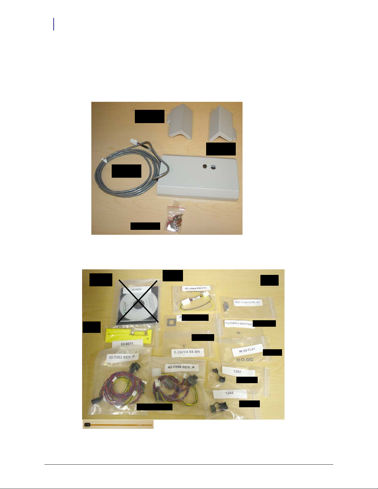
Curved Door
Bracket
Square Door
Bracket
Cam Lock Keys
FlexLock Unit
with cable
Instruction
CD
Blue Screen
Power
Standoffs
#94-6218
Alignmen
t Fixture
Bracket Cutout
AUX cabl es
#94-6233
#94-6158
#94-6138
#91-2052
#91-2051
Kit/Parts Required
Kit/Parts Required
Initial FlexLock installation uses two kits. A third is needed for a TempCheck retrofit. Additional
parts must be ordered from Helmer if attaching a FlexLock to one if its refrigerators.
FlexLock Assembly #14-7043: Some FlexLock parts come pre-assembled for shipping
purposes. They need to be separated to do the installation.
Figure 2-1. FlexLock Kit #14-7043
Installation Kit #20-6023: Includes the TempCheck temperature probe
Figure 2-2. FlexLock Installation Kit #20-6023 with TempCheck probe (#15-7105) [bottom]
FlexLock Installation and Configuration Guide/60-3002 Rev H © 2011 Omnicell, Inc.
Page 11
Hardware Installation 2-3
Kit/Parts Required
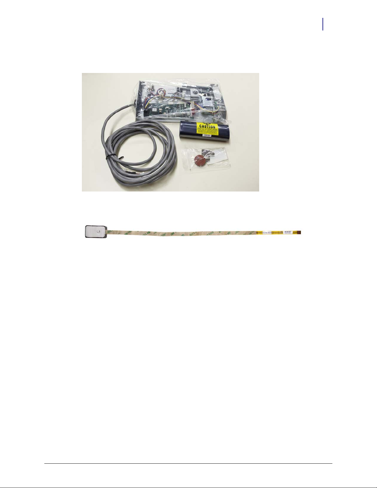
TempCheck Retrofit Kit #20-6037: Includes the FlexLock inner housing with the TempCheck
compatible PCBA #40-3013
Figure 2-3. TempCheck Retrofit Kit #20-6037. Temperature probe shown wrapped in anti-static protection
Temperature probe shown un-wrapped from anti-static protection.
Figure 2-4. Temperature probe and attached ribbon-cable, ready for installation
© 2011 Omnicell, Inc. FlexLock Installation and Configuration Guide/60-3002 Rev H
Page 12
2-4 Hardware Installation
Kit/Parts Required
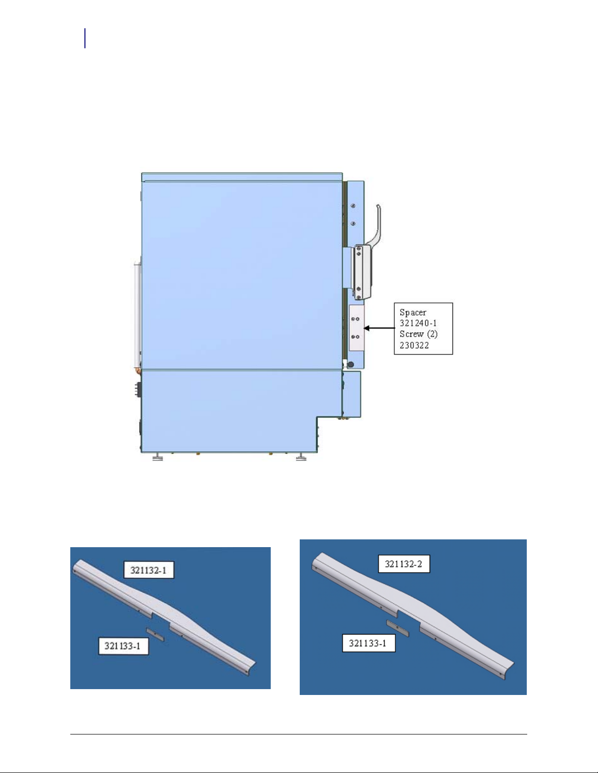
Helmer Parts
Under Counter Refrigerator
1 Spacer (321240-1)
2 Philip screws (230322)
11 Cubic Foot / 20-25 Cubic Foot Refrigerator
Omnicell FlexLock handle: (20-25 cu. ft. = 321132-1) (11 cu. ft. = 321132-2)
Spacer block (321133-1)
FlexLock Installation and Configuration Guide/60-3002 Rev H © 2011 Omnicell, Inc.
Page 13

Hardware Installation 2-5
Kit/Parts Required
Kits
Special accessories are available for facilities that install the Omnicell FlexLock on Helmer upright
refrigerators, undercounter refrigerators, and undercounter freezers.
FlexLock Compatible Door Handles (Upright Models)
The door handle features a cutout and spacer which enable the FlexLock to wrap around the front
and side of the door.
Available for single door upright refrigerators 11, 20, 25, and 26.5 cu ft. (326, 572, 714, 750 l)
Compatible with glass and solid doors
Factory or field installation
FlexLock Adapter Kit (Undercounter Models)
The adapter kit includes an extension bar that mounts to the door of the unit, allowing the
FlexLock to be properly installed.
Adapter kits available for undercounter refrigerators and freezers (5 cu ft. / 142 l)
Compatible with glass and solid doors; powder coated and stainless steel exteriors
Factory installed or field installation kits available
Part # Description Size/Model Notes
400848-2 Omnicell FlexLock Adapter Kit, Factory installed 5 cubic feet (model 142 l) for UC Refrigerators and Freezers
400782-2 Omnicell FlexLock Compatible Door Handle, Factory installed 11 cubic feet (model 326 l)
400782-1 Omnicell FlexLock Compatible Door Handle, Factory installed 20 cubic feet (model 572)
25 cubic feet (model 714)
26.5 cubic feet (model 750 l)
400848-1 Omnicell FlexLock Adapter Kit, Field installation 5 cubic feet (model 142 l) for UC Refrigerators and Freezers)
400875-2 Omnicel l FlexLock Compatible Door Handle, Field instal lation 11 cubic feet (model 326 l)
400875-1 Omnicel l FlexLock Compatible Door Handle, Field instal lation 20 cubic feet (model 572)
25 cubic feet (model 714)
26.5 cubic feet (model 750 l)
© 2011 Omnicell, Inc. FlexLock Installation and Configuration Guide/60-3002 Rev H
Page 14
2-6 Hardware Installation
Installation Instructions
Installation Instructions
Preparation
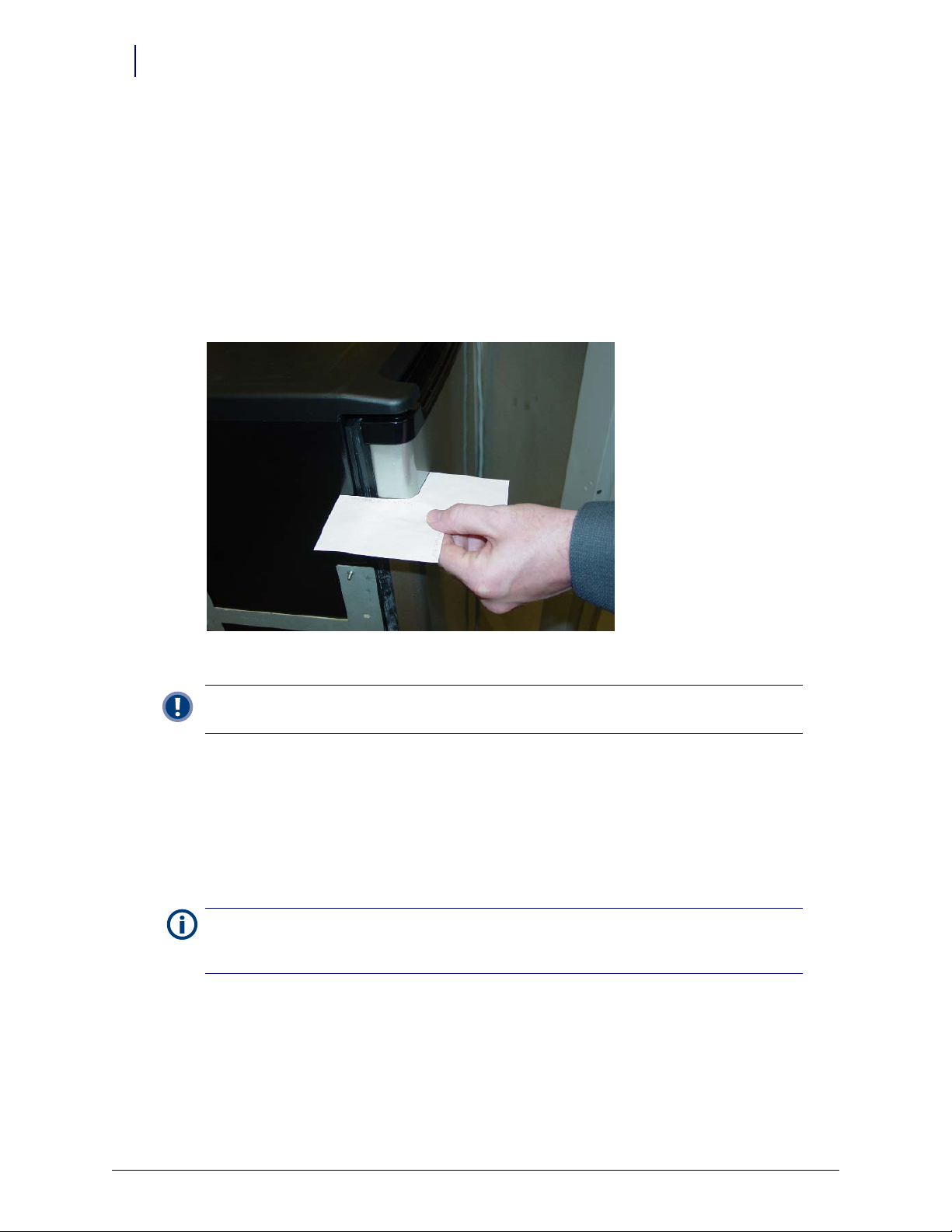
1. Use the template pattern (see “Template” on page C-1) to see if the cabinet or refrigerator is
compatible with the FlexLock. There are two sides of the template—one for a square (90°
ngle) door, the other for a rounded door (used by such manufacturers as Sanyo or Kenmore).
a
a. Align the template to the door and side surface.
b. Make sure there are no gaps.
Figure 2-5. Using the template pattern
Important: Do not attempt to install the FlexLock if the refrigerator door does not fit the template
pattern. See “Compatible Refrigerators” on page A-5 for space requirements and makes/models details.
2. Use an isopropyl alcohol/water mix to clean the refrigerator or cabinet surface where the
FlexLock is to be placed (side where door opens—not the hinged side).
FlexLock Assembly
1. Choose a location on the refrigerator or cabinet—allowing room for the Flexlock and
accessing the refrigerator/cabinet handle.
Note: If installing the TempCheck probe, make sure the cross bar of the mounting bracket is not in line
with a shelf inside the refrigerator. The TempCheck flex circuit should be able run along the inside wall
of the refrigerator.
2. Select the correct door adapter for the door type.
FlexLock Installation and Configuration Guide/60-3002 Rev H © 2011 Omnicell, Inc.
Page 15
Hardware Installation 2-7
Installation Instructions
Door Bracket Assembly
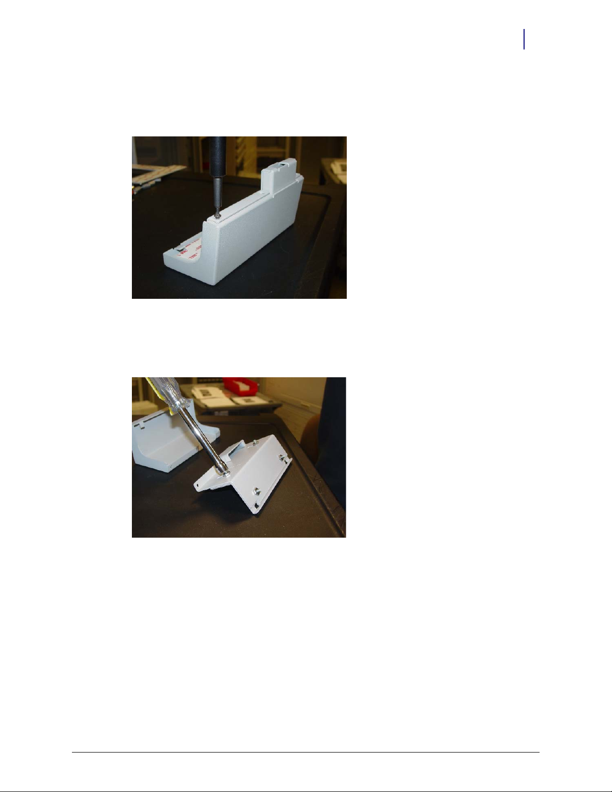
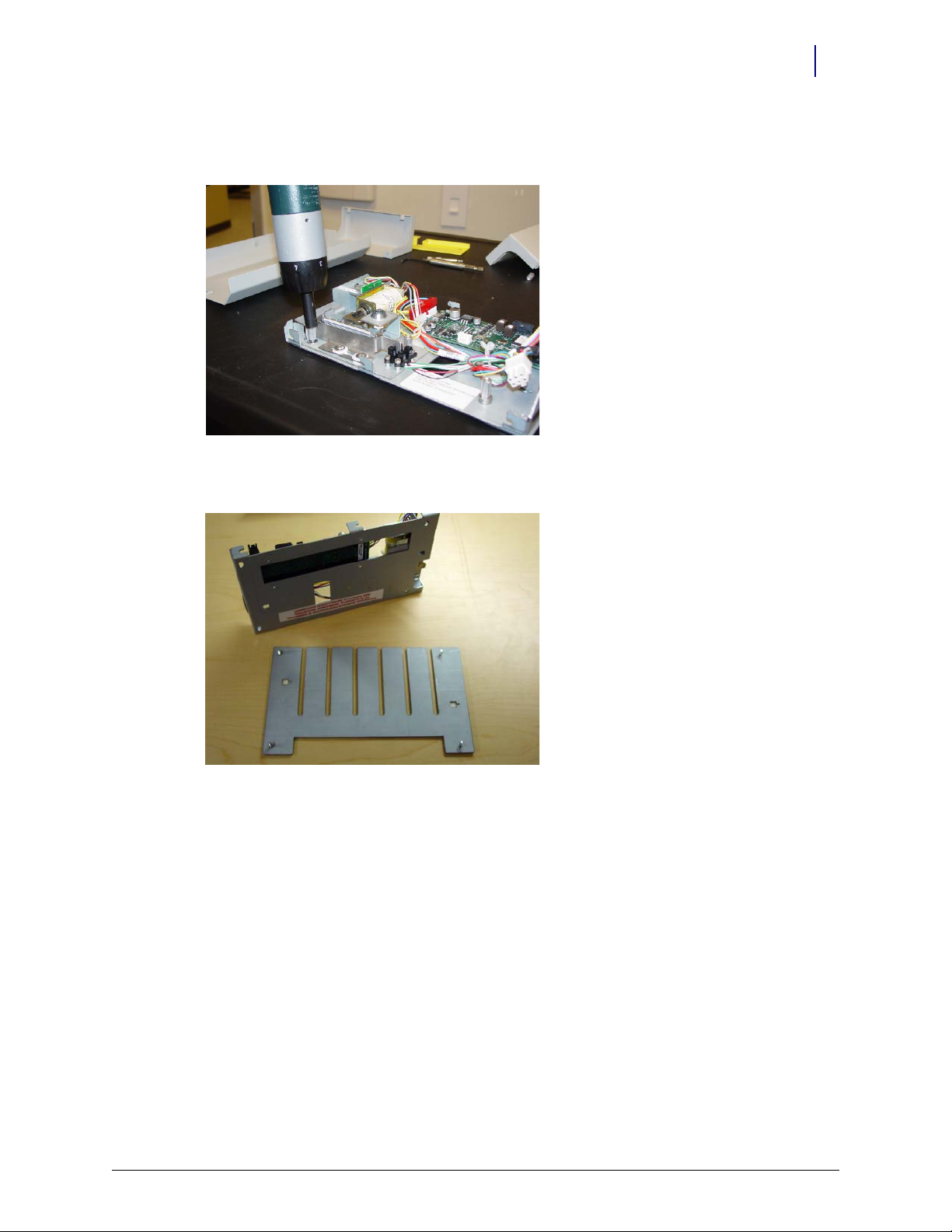
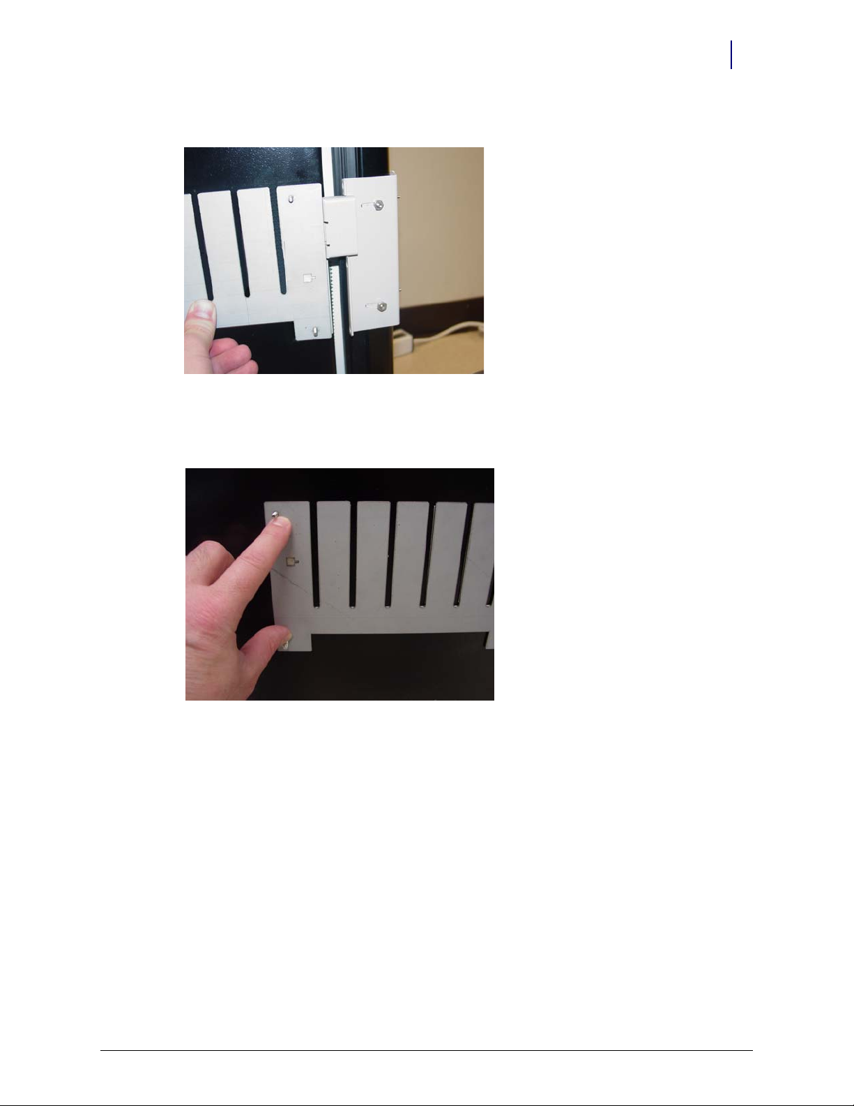
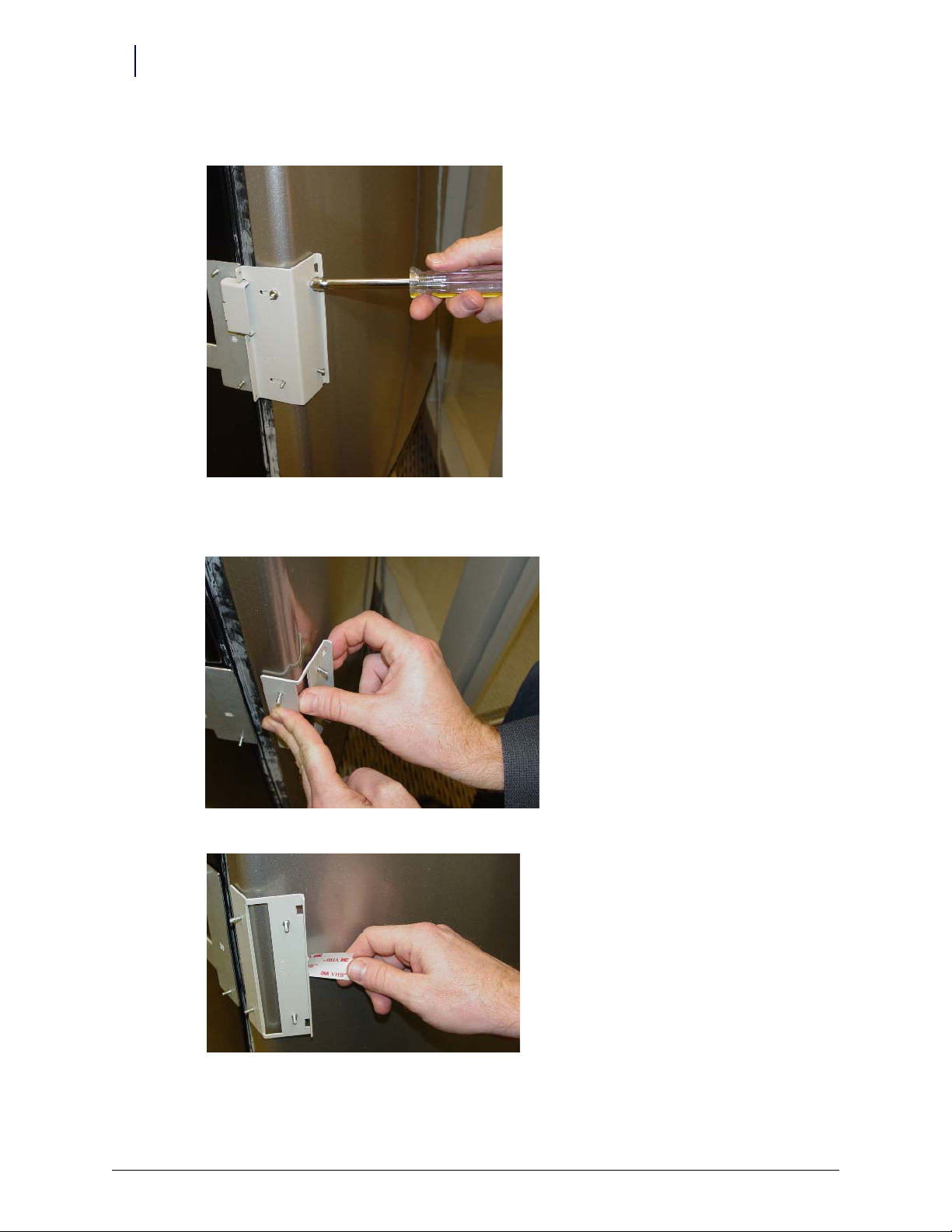
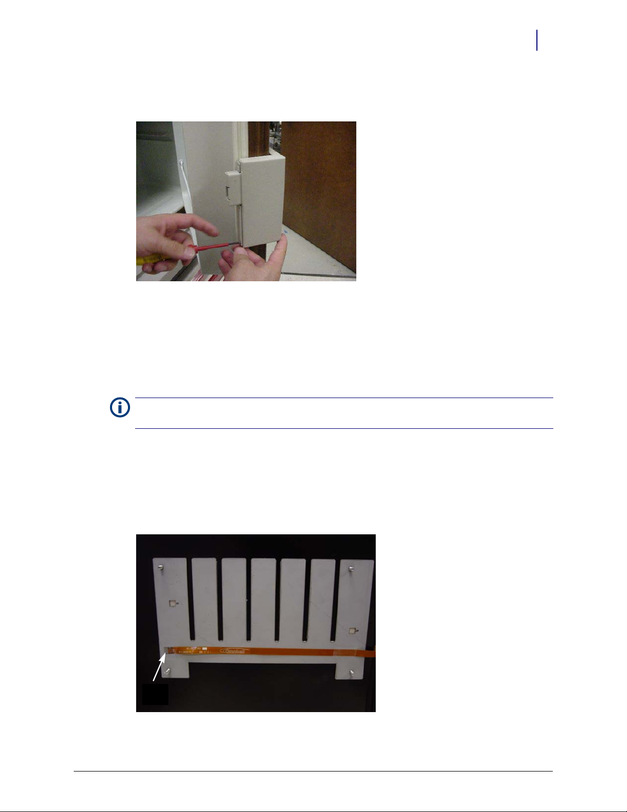
1. Remove the three T-8 screws which hold the cover plate to the door plate using a T-8 Torx
Driver and retain them for later use.
Figure 2-6. Removing the cover plate
2. Remove the cover plate.
3. Remove the four 5/16 nuts which hold the door plate to the plate adapter using a 5/16 nut
driver.
Figure 2-7. Removing the door plate from the plate adapter
4. Remove the door plate.
© 2011 Omnicell, Inc. FlexLock Installation and Configuration Guide/60-3002 Rev H
Page 16
2-8 Hardware Installation
Installation Instructions
Test Fit
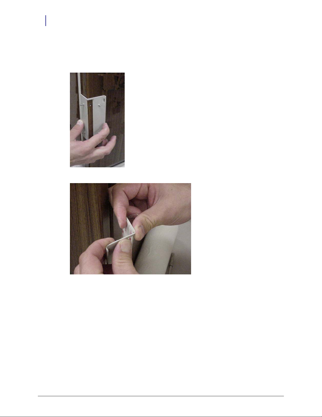
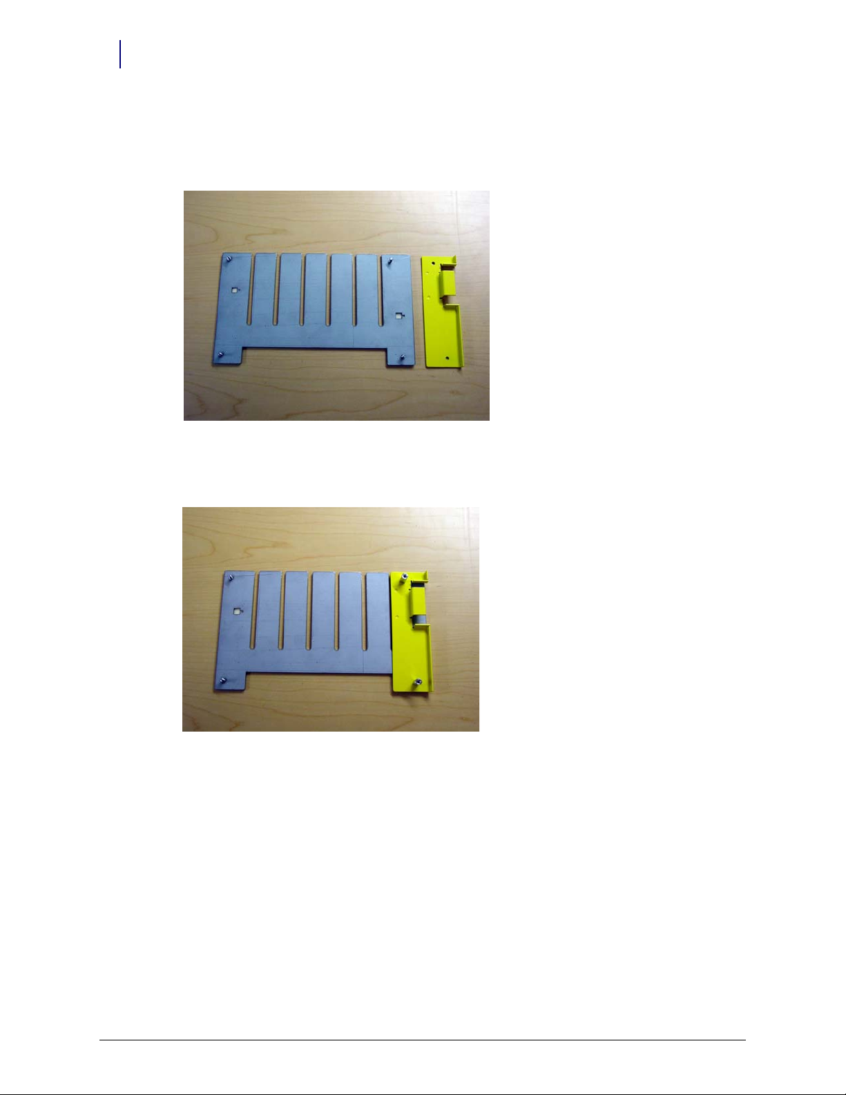
1. Test fit the door adapter against the door corner. Bend the adapter slightly to match the angle
of the refrigerator if needed. A close fit is required for strength.
Figure 2-8. Testing the door adapter fit
Figure 2-9. Bending the door adapter
FlexLock Installation and Configuration Guide/60-3002 Rev H © 2011 Omnicell, Inc.
Page 17
Hardware Installation 2-9
Installation Instructions
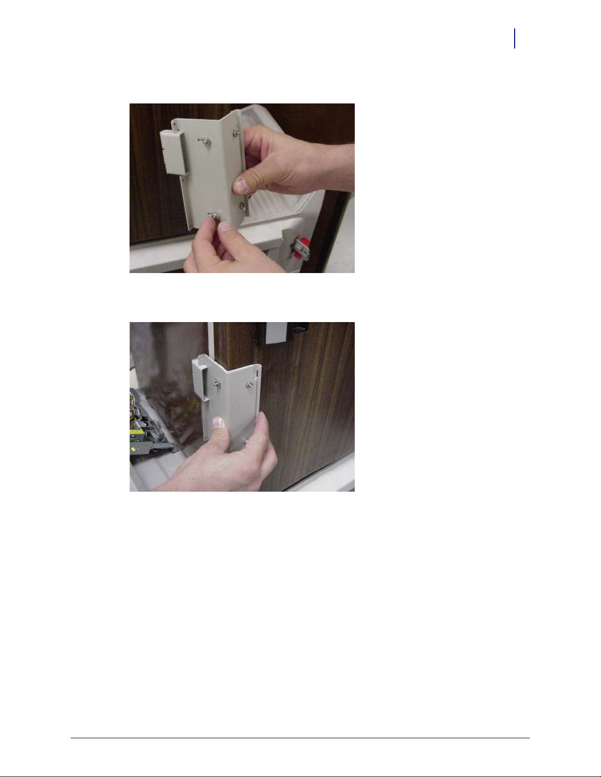
2. Attach the door adapter to the correct door plate using four 5/16” Hex nuts. Hand tighten.
Figure 2-10. Assembling the door brackets
3. Test fit the door bracket assembly against the door corner.
Figure 2-11. Testing the door bracket assembly fit
Helmer Fridge Adjustment
If attaching the FlexLock to a Helmer refrigerator, extra steps and parts are needed. This setup can
take up to 15 minutes. Secure the contents of the refrigerator (if any) in a secure, temperature
controlled container/area during the procedure.
For the 11 cubic feet refrigerator, do the following steps:
1. Remove the existing handle from the door by removing the five mounting screws.
2. Secure the Omnicell Flexlock handle to the door using four of the original screws (two on top
a
nd two at the bottom).
3. Secure the spacer block to the door using the middle screw. Make sure that one edge lines up
w
ith the front face of door.
For the under counter refrigerator, do the following steps:
1. Remove two of the bottom door screws.
© 2011 Omnicell, Inc. FlexLock Installation and Configuration Guide/60-3002 Rev H
Page 18
2-10 Hardware Installation
2 - Lift up
1 - Slide back
Installation Instructions
2. Install the spacer by rotating it into position with the two screw holes aligning with the
mounting holes.
3. Make sure the spacer is flush with the front of the door. If the spacer is not flush, rotate the
s
pacer into position with the other two mounting holes to obtain the flush position.
4. Secure the spacer with two Phillips flat head screws provided with the kit.
Mounting Bracket
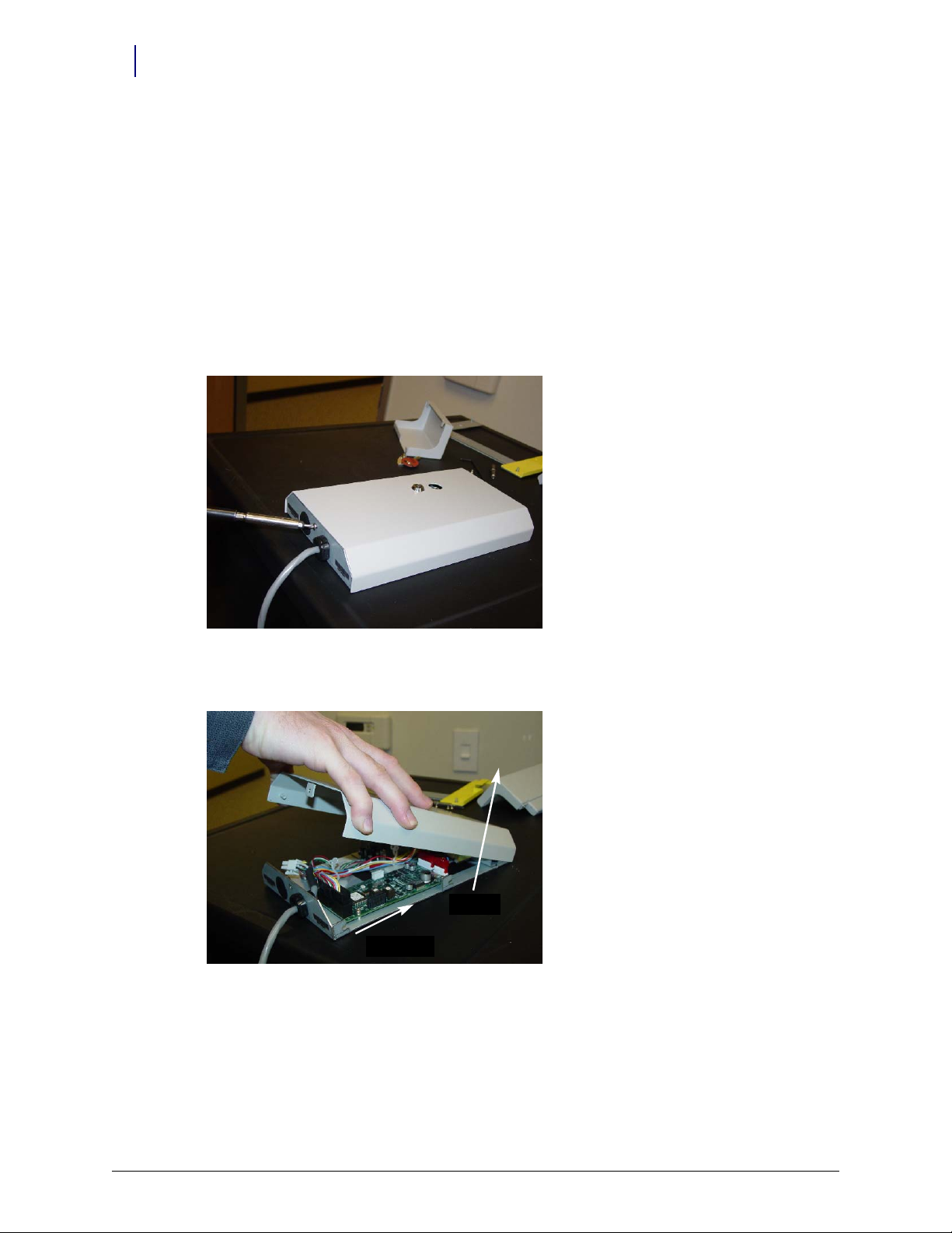
1. Use #2232 cam lock key to move the keyhole cover plate to the open (unlocked) position.
2. Remove the T-10 screw in back with a T-10 Torx driver.
3. Put on an ESD wrist strap and properly ground it.
Figure 2-12. Removing the back screw
4. Slide the outer housing back, then lift off.
Figure 2-13. Removing the outer housing
FlexLock Installation and Configuration Guide/60-3002 Rev H © 2011 Omnicell, Inc.
Page 19
Hardware Installation 2-11
Installation Instructions
5. Remove the four 5/16” hex standoffs in each of the inner housing corners and retain them for
later use.
Figure 2-14. Removing the standoffs
6. Lift the inner housing off.
Figure 2-15. Removing the inner housing
© 2011 Omnicell, Inc. FlexLock Installation and Configuration Guide/60-3002 Rev H
Page 20
2-12 Hardware Installation
Installation Instructions
Alignment Fixture
1. Place the mounting bracket so that the crossbar is toward the bottom and the threaded studs
are facing up.
Figure 2-16. Arranging the bracket assembly
2. Lay the alignment fixture over the right side of the mounting bracket. Align the fixture’s offset
stud holes with the bracket studs. The fixture’s cutout should be facing right.
Figure 2-17. Placing the alignment fixture on the mounting bracket
FlexLock Installation and Configuration Guide/60-3002 Rev H © 2011 Omnicell, Inc.
Page 21
Hardware Installation 2-13
Installation Instructions
3. Use two of the standoffs (removed from the inner housing) to keep the fixture in place. Do not
tighten.
4. Slide in the door bracket assembly’s lock tab into the alignment fixture cutout.
5. Tighten the standoffs.
Figure 2-18. Completed bracket assembly with alignment fixture
Bracket Assembly
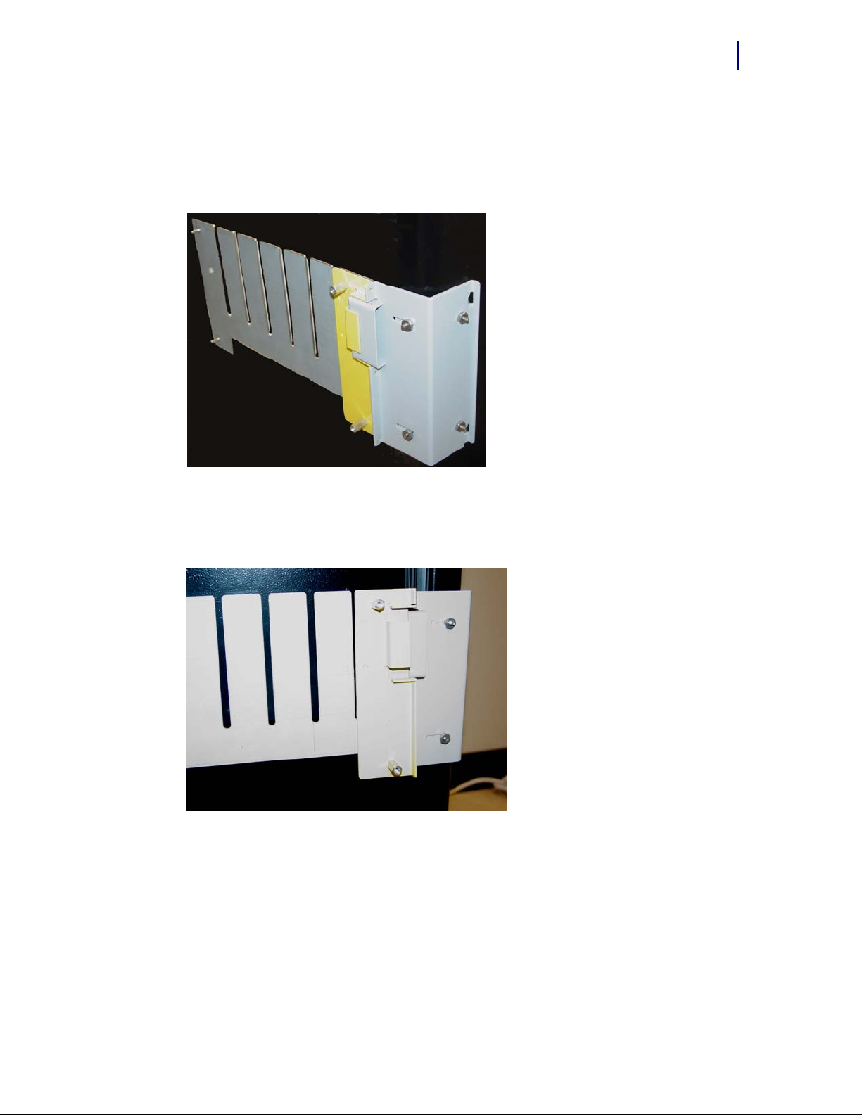
1. Fit the complete bracket assembly on the cabinet/refrigerator.
Figure 2-19. Fitting the whole bracket assembly
© 2011 Omnicell, Inc. FlexLock Installation and Configuration Guide/60-3002 Rev H
Page 22
2-14 Hardware Installation
Installation Instructions
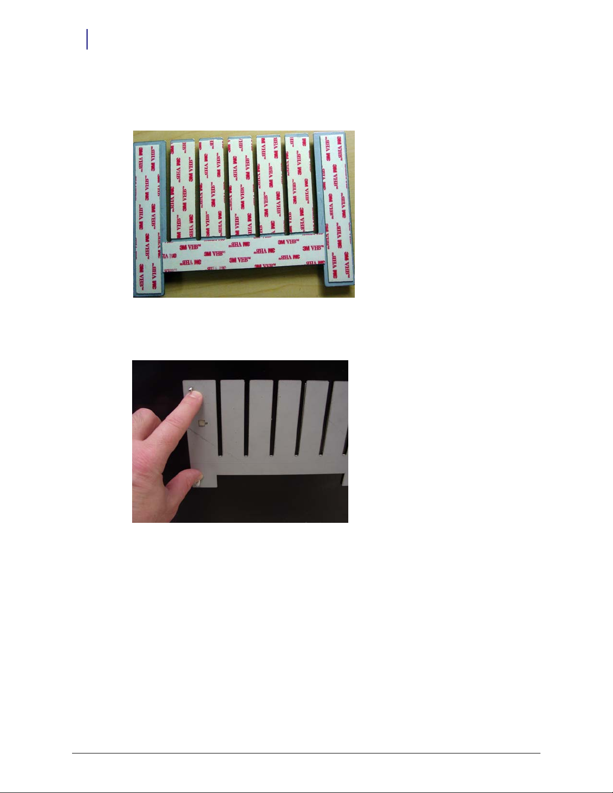
2. Turn the brackets over and remove the protective film from the adhesive strips for the
mounting bracket and the side of the inner door bracket. Leave the film cover on the strip that
will go on the front of the door.
Figure 2-20. Removing adhesive strip covers
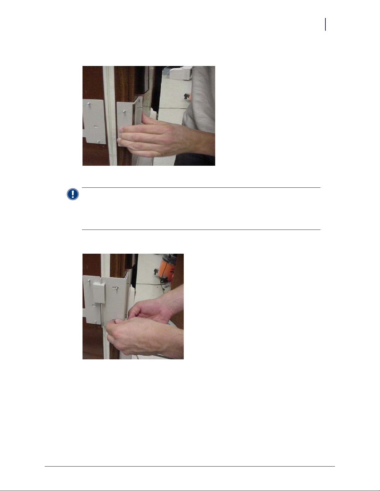
3. Fit the door bracket assembly to the cabinet/refrigerator and press firmly on the mounting
bracket and the side of the door bracket assembly.
Figure 2-21. Bonding the bracket assembly
FlexLock Installation and Configuration Guide/60-3002 Rev H © 2011 Omnicell, Inc.
Page 23
Hardware Installation 2-15
Installation Instructions
4. Remove the alignment fixture.
Figure 2-22. Bracket assembly without the alignment fixture
5. Open the refrigerator/cabinet door.
6. Press firmly on the mounting bracket to assure the adhesive has full contact.
Figure 2-23. Pressing the mounting bracket
7. Close the refrigerator/cabinet door.
© 2011 Omnicell, Inc. FlexLock Installation and Configuration Guide/60-3002 Rev H
Page 24
2-16 Hardware Installation
Installation Instructions
8. Remove the four 5/16” hex nuts to remove the door plate.
Figure 2-24. Removing the door plate
9. Bend the door adapter back slightly to peel off the adhesive strip cover.
Figure 2-25. Bending the door adapter
Figure 2-26. Stripping the adhesive cover
FlexLock Installation and Configuration Guide/60-3002 Rev H © 2011 Omnicell, Inc.
Page 25
Hardware Installation 2-17
Installation Instructions
10. Press the door adapter firmly in place, to assure full contact from the adhesive.
Figure 2-27. Bonding the door adapter
Important: Wait until the bond is set before proceeding to the next step. At room temperature, it will
take 20 minutes for 50% bond strength; 24 hours for 90% bond strength; 72 hours for 100% bond
strength. The process can be sped up by increasing the temperature 150° F for an hour.
If applicable, the TempCheck probe can be installe
to“TempCheck Installation” on page 2-19.
d while waiting for the bonding process. Refer
11. Re-attach the door plate to the door adapter and tighten the four 5/16” nuts.
Figure 2-28. Re-attaching the door plate
12. Open the door of the refrigerator/cabinet.
© 2011 Omnicell, Inc. FlexLock Installation and Configuration Guide/60-3002 Rev H
Page 26
2-18 Hardware Installation
Installation Instructions
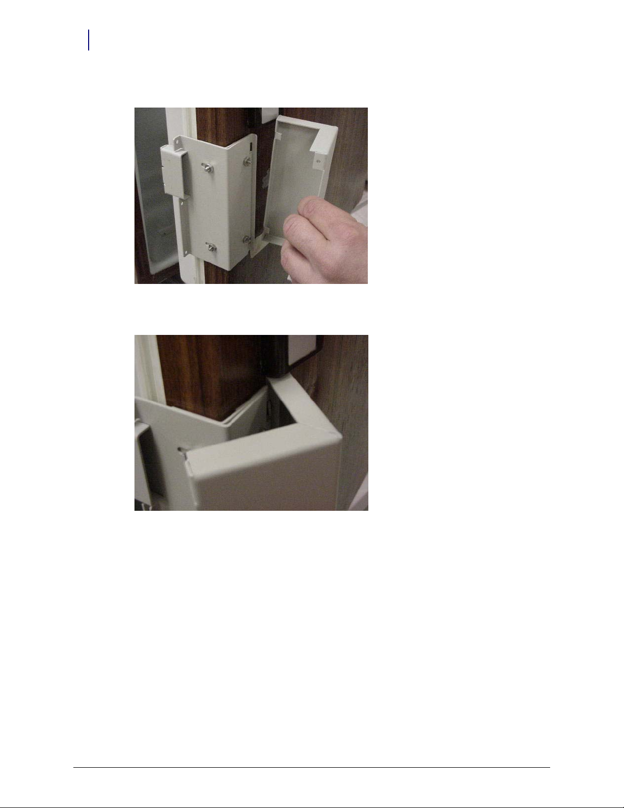
13. Match the notches on the cover plate to the door plate openings.
Figure 2-29. Matching notches
14. Move the cover plate forward until it fits without gaps.
Figure 2-30. Placing the cover plate
FlexLock Installation and Configuration Guide/60-3002 Rev H © 2011 Omnicell, Inc.
Page 27
15. Secure the cover plate to the door plate with the three retained T-8 Torx screws to the side of
Circuit
Contac ts
the front cover.
Figure 2-31. Securing the cover plate
TempCheck Installation
Hardware Installation 2-19
Installation Instructions
This section provides instructions for the optional installation of a TempCheck temperature probe
with a new FlexLock. If performing a TempCheck retrofit for an existing FlexLock, refer to
“Retrofit TempCheck” on
“Inner Housing and Cover” on
page 2-81. If not using this optional feature, skip to the next section—
page 2-21.
Note: Most refrigerators have doors that open from the left (door hinges on the right side). If the door opens
from the right side, some installation parts must be inverted.
1. Clean the intended path of the TempCheck probe flex circuit inside the refrigerator with a
isopropyl alcohol/water mix. The path should be level with the mounting bracket’s crossbar
and not in line with a refrigerator shelf. The probe is placed on the side closest to the
opening—opposite the hinges.
2. Align the contacts end of the flex circuit to the edge of the FlexLock mounting bracket and
temporarily attach it with adhesive tape. Avoid taping over the circuit contacts at the end.
Figure 2-32. Aligning the end of the Flex Circuit with bracket.
© 2011 Omnicell, Inc. FlexLock Installation and Configuration Guide/60-3002 Rev H
Page 28
2-20 Hardware Installation
Installation Instructions
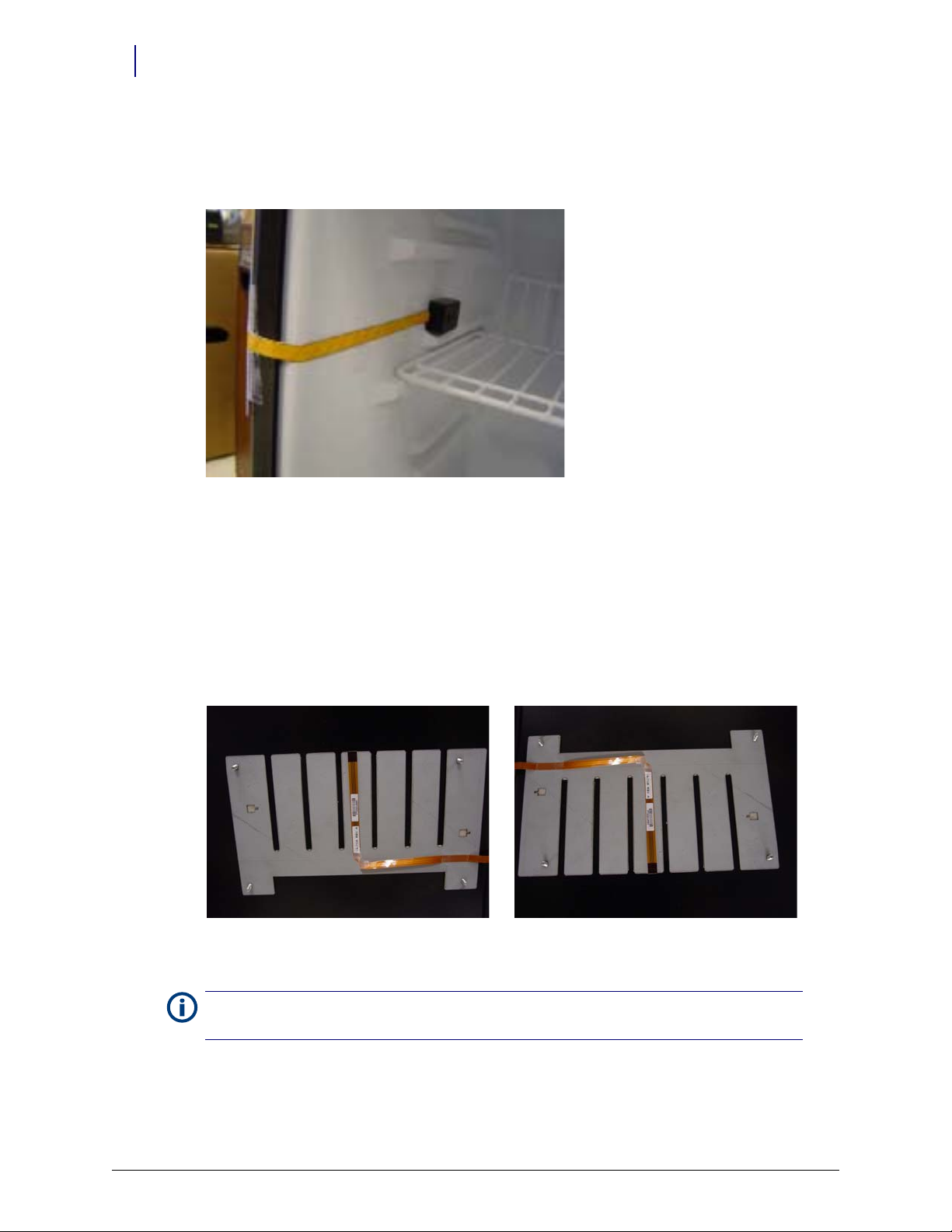
3. Pull the flex circuit tight inside the refrigerator door.
4. Install the temperature sensor end inside the refrigerator. Remove the self-adhesive cover and
p
ull the flex circuit tight while sticking it in place.
Figure 2-33. Installing the sensor inside the refrigerator.
5. Remove the tape from the contacts end of the flex circuit.
6. Peel off the self-adhesive cover from the flex circuit.
7. Pull the flex circuit tight while carefully adhering it from inside the refrigerator to the mid
po
int of the mounting bracket.
8. Bend the exposed end of the flex circuit at a ninety degree angle. Bend up for refrigerators that
o
pen from the left...or down for refrigerators that open from the right. The exposed contacts
should be facing the refrigerator wall in either case.
Figure 2-34. Bending the Flex Circuit end up (refrigerator opens from left)............or down (refrigerator opens from right).
Note: Be sure to complete the “Bracket Assembly” steps before going to the “Inner Housing and Cover”
section.
FlexLock Installation and Configuration Guide/60-3002 Rev H © 2011 Omnicell, Inc.
Page 29
Inner Housing and Cover
1. Place the inner housing over the mounting bracket’s threaded studs. If applicable, thread the
TempCheck flex circuit through the inner housing opening.
Figure 2-35. Placing the Inner Housing in position.
Hardware Installation 2-21
Installation Instructions
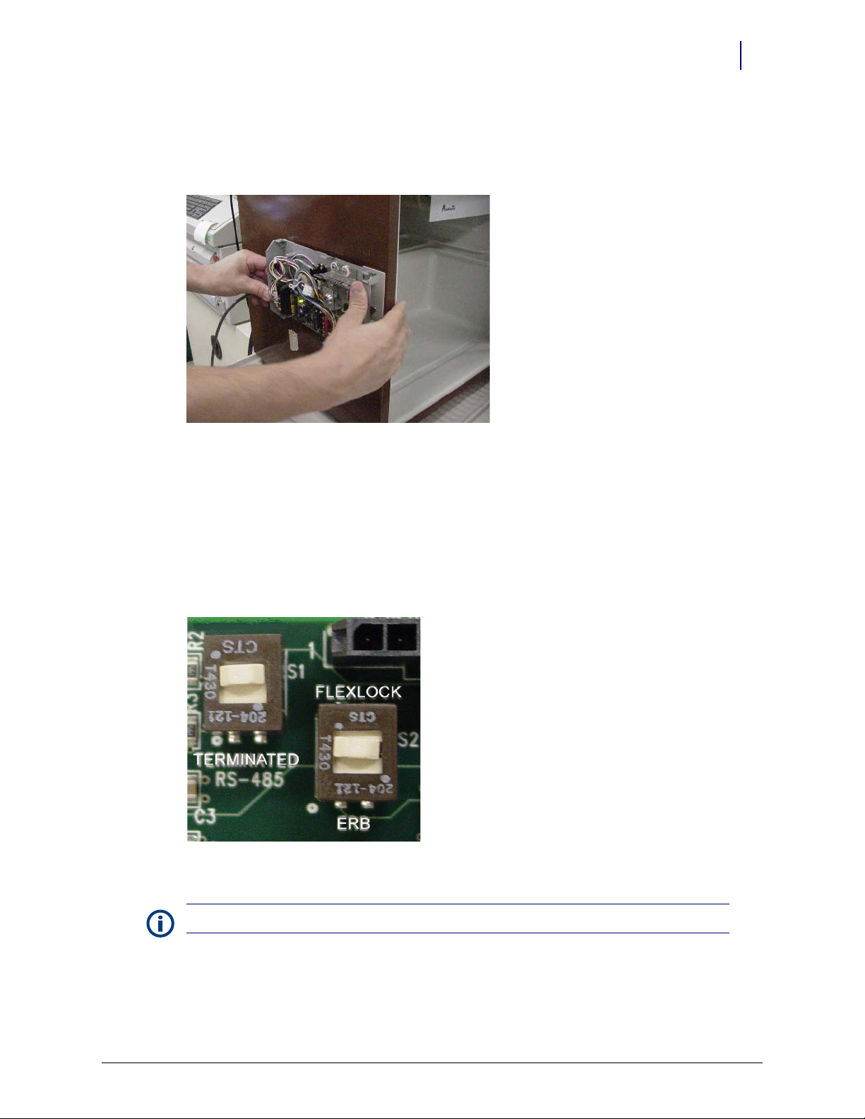
2. Place a washer on the threaded studs, then tighten the four standoffs.
3. Set the PCBA S1 slide switch to either: (see Fi
Terminated—if the FlexLock is at the end of the AUX daisy chain or the only AUX device
Not Terminated (not marked on PCBA)—if in the middle of a daisy chain with an External
Return Bin (ERB) or another FlexLock cabled to it
4. Set the PCBA S2 slide switch to FlexLock.
Figure 2-36. Checking the PCBA Switch Settings.
gure 2-34)
Note: The PCBA switch labels will be upside down when the inner housing is installed.
© 2011 Omnicell, Inc. FlexLock Installation and Configuration Guide/60-3002 Rev H
Page 30
2-22 Hardware Installation
ZIF Connector
ZIF Connector
1
2
Installation Instructions
5. If installing the TempCheck probe:
a. Pull out the Zero Insertion Force (ZIF) connector collar so that it is in the up (unlocked)
b. Loop the TempCheck probe flex circuit around without twisting to plug it into the ZIF
c. Insert the flex circuit into the connector, then evenly press the ZIF connector collar down
po
sition.
co
nnector. The flex circuit contacts should be facing down (if refrigerator opens from the
left) or up (if refrigerator opens from the right).
to the locked position.
in
Figure 2-37. Connecting the Flex Circuit in the Housing Assembly
6. Install the FlexLock housing cover by (1) placing it over the inner housing offset to the front,
then (2) sliding it back.
Figure 2-38. Placing the Housing Cover in position.
FlexLock Installation and Configuration Guide/60-3002 Rev H © 2011 Omnicell, Inc.
Page 31

Alignment
1
2
3
standoffs
standoffs
release
housing
opening
shims
crosshair
crosshair
Hardware Installation 2-23
Installation Instructions
1. Close the refrigerator (or cabinet) door to check the lock assembly for clearance in three
places.
The lock assembly should be vertically centered so that the gap at point 1 is the same as
point 2.
The lock tab should move in/out of the locking slot with no interference at point 3.
Figure 2-39. Checking the locking assembly.
2. If alignment adjustments are needed, remove the cover.
Figure 2-40. Alignment Features
3. To add space between the mounting bracket and the inner housing assembly:
a. Pull the ZIF connector collar up to release the TempCheck flex circuit if present.
b. Remove the four corner standoffs and washers.
c. Remove the inner housing. Thread the flex circuit out of the housing opening if present.
© 2011 Omnicell, Inc. FlexLock Installation and Configuration Guide/60-3002 Rev H
Page 32

2-24 Hardware Installation
washers/shims
Installation Instructions
d. Remove the standoff (2nd left on inner housing) holding the extra washers.
Figure 2-41. Washer/Shims under standoff
e. Remove the washers and replace the standoff.
f. Use the washers as shims by placing th
g. Place the inner housing on the threaded studs now with shims.
h. Re-thread the TempCheck flex circuit back through the housing opening if present.
em on the four threaded studs.
i. Place a washer on the threaded studs then tighten the four standoffs.
Figure 2-42. Adding space with shims
j. If installing the TempCheck probe:
1. Pull out the Zero Insertion Force (ZIF) connector collar so that it is in the up
(un
locked) position.
2. Loop the flex circuit around to plug it into the ZIF connector. The exposed metal
co
ntact portion of the flex circuit end should be facing down.
3. Evenly press the ZIF connector collar down into the locked position.
FlexLock Installation and Configuration Guide/60-3002 Rev H © 2011 Omnicell, Inc.
Page 33

Hardware Installation 2-25
Installation Instructions
4. Set the vertical alignment if needed.
a. Loosen the standoffs as needed.
b. Use a screwdriver with the two cross hairs. The screwdriver slot adjustment sets the
posi
tion up and down from neutral. The neutral position is when the cross hairs are aligned
in a cross formation.
c. Tighten the standoffs.
Figure 2-43. Aligning the inner housing with the Cross Hair.
5. To adjust the inner plate of the Lock Pawl:
a. Loosening the middle and two right standoffs.
b. Adjust pawl horizontally as needed.
c. Re-tighten the standoffs.
6. Replace the housing cover.
7. Secure the housing cover with one T-10 Torx screw.
Figure 2-44. Securing the housing cover.
© 2011 Omnicell, Inc. FlexLock Installation and Configuration Guide/60-3002 Rev H
Page 34

2-26 Hardware Installation
Cabling on G3 cabinets
Cabling on G3 cabinets
This section provides instructions for various FlexLock cable retrofits to G3 hardware.
Cabling for the G3 OmniTT, Omni Rx, Half-Cell, Anesthesia Workstation (AWS) and Anesthesia Table
Top (AWS TT)
Connect the FlexLock to the G3 version of the OmniTT, Omni Rx, Half-Cell, Anesthesia
Workstation (AWS) and Anesthesia TableTop (AWS TT) using the wiring procedure described in
“Cabling for the OmniTT G3” on page 2-27.
Cabling for the OmniSupplier G3
Connect the FlexLock to the OmniSupplier using the wiring procedure described in“Cabling for
the OmniSupplier G3” on page 2-32.
FlexLock Installation and Configuration Guide/60-3002 Rev H © 2011 Omnicell, Inc.
Page 35

Cabling for the OmniTT G3
This section provides instructions for attaching a FlexLock to the following cabinet types:
OmniTT
OmniRX
Half Cell Cabinet
Anesthesia Workstation
AnesthesiaTT
1. Power down the cabinet.
Caution
: Put on an ESD wrist strap and ground it before working on the cabinet electronics.
2. Access the electronics sled.
a. Lift up the sled cover.
b. Prop open using a switch panel housing.
Hardware Installation 2-27
Cabling on G3 cabinets
Figure 2-45. Propping the sled cover
Note: The Anesthesia Workstation sled cover can be removed completely.
3. Remove both AUX cable connectors at the rear of the electronic sled by pushing down on the
AUX connector and pulling it out through the back.
© 2011 Omnicell, Inc. FlexLock Installation and Configuration Guide/60-3002 Rev H
Page 36

2-28 Hardware Installation
Cabling on G3 cabinets
Figure 2-46. Removing the AUX connectors
4. Unplug the 4 pin connector from AUX J24 (US Logic/Windows 95) or J10 (ETX/Windows XP)
on the power-comm board.
5. Remove the cable.
Figure 2-47. AUX cable removed
FlexLock Installation and Configuration Guide/60-3002 Rev H © 2011 Omnicell, Inc.
Page 37

Hardware Installation 2-29
Aux
Conne ctor
FlexLock
Connector
Power
Connector
Communications
Connector
Cabling on G3 cabinets
6. Insert the black AUX connector from the Omnicell FlexLock retrofit AUX cable assembly into
the first opening.
Figure 2-48. #42-7052 AUX Cable Assembly
7. Refer to the following table when connecting the 4-pin and 3-pin cables.
Board Type Com 4-Pin Connection Power 3-Pin Connection
US Logic This motherboard does not support auxiliary cabinets, FlexLock or ERB.
OmniRx Power Com (40-7056) J10 J4, J5 (MAG), J16
Power Com2 (40-1015) J16 4-pin HDD power connector from
/DC power supply
AC
Power Com3 (40-1021, 1050) J20 J4 / J5 / J6
a. Insert the 4-pin connector into the appropriate port (varies by board).
Figure 2-49. Connecting the communications cable
© 2011 Omnicell, Inc. FlexLock Installation and Configuration Guide/60-3002 Rev H
Page 38

2-30 Hardware Installation
Cabling on G3 cabinets
b. Insert the 3-pin (blue and yellow cables) connector from the retrofit AUX cable assembly
Figure 2-50. Connecting the power cable
8. Thread the Omnicell FlexLock cable (white) through the 2nd AUX opening.
9. Slip the metal retaining bracket (1” square) over the white connector and position it on the
inside rear of the metal rail.
into the appropriate port (varies by board).
Figure 2-51. Positioning the retaining bracket
FlexLock Installation and Configuration Guide/60-3002 Rev H © 2011 Omnicell, Inc.
Page 39

Hardware Installation 2-31
Cabling on G3 cabinets
10. Connect the FlexLock cable to the cable assembly.
Figure 2-52. Connecting the FlexLock cable
11. Snap on the black strain relief over the outside Omnicell FlexLock Power Comm cable and
push it half way through the 2nd AUX opening. The metal retainer should snap into the
oove of the black strain relief and secure the cable to the inside of the rear panel.
gr
Figure 2-53. Snapping on the strain relief
12. Tuck all the cables out of the way. Use cable ties as needed.
13. Close the sled cover.
14. Remove the ESD wrist strap.
15. Switch the power on.
16. Proceed to “Software Implementation” on
page 3-1 for software configuration instructions for
FlexLock and TempCheck if installed.
© 2011 Omnicell, Inc. FlexLock Installation and Configuration Guide/60-3002 Rev H
Page 40

2-32 Hardware Installation
Aux
Conne ctor
FlexLock/ER B
Conne ctor
Power
Conne ctor
Communications
Conne ctor
Cabling on G3 cabinets
Cabling for the OmniSupplier G3
Use these steps when connecting a FlexLock to an OmniSupplier.
1. Power down the cabinet.
Caution
: Put on an ESD wrist strap and ground it before working on the cabinet electronics.
2. Access the PC Box.
3. Remove both AUX cable connectors at the rear of the PC box by pushing down on the AUX
co
nnector and pulling it out through the back.
Figure 2-54. Removing the AUX connectors from the PC box
4. Unplug the 4-pin connector from Aux Com J16 on the power-comm board.
5. Remove the AUX cable.
6. Insert the black AUX connector from the Omnicell FlexLock retrofit AUX cable assembly into
the first opening.
Figure 2-55. AUX Cable Assembly #42-7058
FlexLock Installation and Configuration Guide/60-3002 Rev H © 2011 Omnicell, Inc.
Page 41

Hardware Installation 2-33
AUX COM
Cabling on G3 cabinets
7. Insert the 4 pin header connector on the retrofit AUX cable assembly into J16, labeled AUX
COM on the UPS board.
Figure 2-56. Connecting the communication cable
8. Insert the power (blue and yellow cables) connector from the retrofit AUX cable assembly into
power supply connector.
Figure 2-57. Connecting the power cable
© 2011 Omnicell, Inc. FlexLock Installation and Configuration Guide/60-3002 Rev H
Page 42

2-34 Hardware Installation
Cabling on G3 cabinets
9. Thread the Omnicell FlexLock cable (white) through the 2nd AUX opening and connect it to
the cable assembly.
Figure 2-58. Connecting the FlexLock cable
10. Slip the metal retaining bracket (1” square) over the white connector and position it on the
inside rear of the metal rail.
11. Snap on the black strain relief over the outside Omnicell FlexLock Power Comm cable and
push it half way through the 2nd AUX opening. The metal retainer should snap into the
gr
oove of the black strain relief and secure the cable to the inside of the rear panel.
Figure 2-59. Inside view of bracket and strain relief
12. Tuck all the cables out of the way. Use cable ties as needed.
FlexLock Installation and Configuration Guide/60-3002 Rev H © 2011 Omnicell, Inc.
Page 43

13. Secure the PC Box.
Strain Relief
AUX Con nector
Figure 2-60. Rear View of OmniSupplier PC Box
14. Remove the ESD wrist strap.
15. Switch the power on.
16. Proceed to “Software Implementation” on
FlexLock and TempCheck if installed.
Hardware Installation 2-35
Cabling on G3 cabinets
page 3-1 for software configuration instructions for
© 2011 Omnicell, Inc. FlexLock Installation and Configuration Guide/60-3002 Rev H
Page 44

2-36 Hardware Installation
Cabling on G3 Cabinets with G4 Console Upgrade
Cabling on G3 Cabinets with G4 Console Upgrade
This section provides instructions for various FlexLock cable retrofits to G3 hardware that has
been upgraded with G4 control electronics.
Cabling for the AWS G3 with G4 console upgrade
Connect the FlexLock to the G3 AWS upgraded to G4, using the wiring procedure described in
“Cabling for the Anesthesia Workstation G3 with the G4 Upgrade” on page 2-37.
Cabling for the OmniTT, Omni Rx and Half-cell cabinets with G3 to G4 Console Upgrades
Connect the FlexLock to the OmniTT G3 with G4 upgrade using the same wiring procedures as
for the OmniTT G4 described in
Cabling for the One-, Two-, Three Cell with a G4 Console Upgrade
Connect the FlexLock to the G3 with G4 upgrade cabinet using the wiring procedure described in
“Cabling for the One-, Two-, Three-Cell G4 Cabinets” on page 2-56.
“Cabling for the OmniTT G4” on page 2-44.
FlexLock Installation and Configuration Guide/60-3002 Rev H © 2011 Omnicell, Inc.
Page 45

Cabling for the Anesthesia Workstation G3 with the G4 Upgrade
1. .Remove the work-surface.
a. Swivel the monitor out of the way.
Hardware Installation 2-37
Cabling on G3 Cabinets with G4 Console Upgrade
Figure 2-61. Monitor swiveled away from work-surface
b. Use the cam lock key #2036 to unlock the work-surface.
c. Tilt the work-surface up, pull it forward, then lift it up and away. Set it aside.
Figure 2-62. Tilting the work-surface
© 2011 Omnicell, Inc. FlexLock Installation and Configuration Guide/60-3002 Rev H
Page 46

2-38 Hardware Installation
Cabling on G3 Cabinets with G4 Console Upgrade
Figure 2-63. Pulling the work-surface forward
2. Remove the plate on the upper left of the rear panel of the electronics sled.
a. On the left side of the electronics sled, inside the cabinet, remove the screw that attaches
th
e plate to the frame.
b. Press the plate to the inside to remove it.
Figure 2-64. Location of the plate-retention screw
FlexLock Installation and Configuration Guide/60-3002 Rev H © 2011 Omnicell, Inc.
Page 47

Cabling on G3 Cabinets with G4 Console Upgrade
3. Feed the FlexLock Power/Com. cable through the resulting hole
.
Figure 2-65. Feeding the FlexLock Power/Com. cable through the slot opened by removing the plate
Hardware Installation 2-39
4. Connect the FlexLock adapter cable to the E-Box.
Figure 2-66. E-Box connection point for FlexLock on AWS G3 with G4 console upgrade
© 2011 Omnicell, Inc. FlexLock Installation and Configuration Guide/60-3002 Rev H
Page 48

2-40 Hardware Installation
Cabling on G3 Cabinets with G4 Console Upgrade
5. Route the gray FlexLock Power/Com. cable around the front of the E-Box and connect it to the
adapter cable.
Figure 2-67. Routing the FlexLock cable around the front of the E-Box
Figure 2-68. FlexLock Power/Com. cable connected to FlexLock adapter cable
FlexLock Installation and Configuration Guide/60-3002 Rev H © 2011 Omnicell, Inc.
Page 49

Hardware Installation 2-41
Cabling on G3 Cabinets with G4 Console Upgrade
6. Position the Flex Lock Power/Com. cable in the slot in the plate removed in step 2.
Figure 2-69. Showing the right-side cable exit from the outside of the cabinet
7. Check the cable inside the cabinet for proper alignment, then secure the plate with the original
fastener.
Figure 2-70. Interior view of the cable exit as it passes through the slot in the rear panel
© 2011 Omnicell, Inc. FlexLock Installation and Configuration Guide/60-3002 Rev H
Page 50

2-42 Hardware Installation
Cabling on G3 Cabinets with G4 Console Upgrade
8. If required, bundle excess FlexLock Power/Com. cable inside the chassis using cable ties.
Figure 2-71. Use zip-ties to secure excess cable
9. Secure the FlexLock Power/Com. cable to the bracket on the inside of the chassis for strain
relief.
Figure 2-72. Use zip-ties to secure the cable to the chassis and provide strain relief
10. Replace the work-surface on the cabinet and lock it.
FlexLock Installation and Configuration Guide/60-3002 Rev H © 2011 Omnicell, Inc.
Page 51

Cabling on G4 Cabinets
This section provides instructions for various FlexLock cable retrofits to G4 hardware.
Cabling for the OmniTT G4, OmniRx G4 and Half-Cell G4
Connect the FlexLock to the OmniTT, the OmniRx G4 and Half-Cell G4 using the wiring
procedure described in
Cabling for One-, Two-, Three-Cell G4 Cabinets
Connect the FlexLock to One-, Two, and Three-Cell G4 Cabinets using the wiring procedure
described in
Cabling for the Anesthesia Workstation (AWS) G4
Connect the FlexLock to the AWS G4 using the wiring procedure described in “Cabling for the
Anesthesia Workstation (AWS) G4” on page 2-43
“Cabling for the One-, Two-, Three-Cell G4 Cabinets” on page 2-56
Hardware Installation 2-43
Cabling on G4 Cabinets
“Cabling for the OmniTT G4” on page 2-44.
© 2011 Omnicell, Inc. FlexLock Installation and Configuration Guide/60-3002 Rev H
Page 52

2-44 Hardware Installation
Cabling on G4 Cabinets
Cabling for the OmniTT G4
If possible the FlexLock should be installed on the left side (monitor side) of the OmniTT G4, to
reduce cable-strain relief.
Cabling for the FlexLock on the left side of the Cabinet
1. Remove the lid from the cabinet.
a. Use the #2378 cam lo
ck key to unlock the lid.
Figure 2-73. Unlocking the lid
b. Rotate the lid up to release it from the chassis hooks and place it aside.
Figure 2-74. Removing the lid
Note: Although it is possible to prop the cover open with the kick-stand, removing it provides better
access.
FlexLock Installation and Configuration Guide/60-3002 Rev H © 2011 Omnicell, Inc.
Page 53

Hardware Installation 2-45
Cabling on G4 Cabinets
2. Holding the notch on the back of the printer paper holder, rotate the printer paper holder
forward and remove it.
Figure 2-75. Removing the paper holder
3. Use a flat-head screwdriver to remove the metal cutout on the back of the cabinet, rocking it
back and forth until the metal breaks away.
Figure 2-76. Opening the slot for the FlexLock Power/Com. cable
© 2011 Omnicell, Inc. FlexLock Installation and Configuration Guide/60-3002 Rev H
Page 54

2-46 Hardware Installation
Cabling on G4 Cabinets
Figure 2-77. FlexLock Power/Com. cable slot location
Note: A limited number of systems might not have this cutout. In such a case, it is necessary to route
the cable on the right, see “Cabling for the FlexLock on the right side of the Cabinet” on
page 2-52
FlexLock Installation and Configuration Guide/60-3002 Rev H © 2011 Omnicell, Inc.
Page 55

4. Pass the FlexLock Power/Com. cable through the opening.
Figure 2-78. Passing the FlexLock Power/Com. cable through opening
Hardware Installation 2-47
Cabling on G4 Cabinets
Figure 2-79. Measuring length of cable inside cabinet
Note: Do not secure the ERB Power/Com. cable with the grommet yet to allow slack for routing the
cable around the electronics sled.
© 2011 Omnicell, Inc. FlexLock Installation and Configuration Guide/60-3002 Rev H
Page 56

2-48 Hardware Installation
Cabling on G4 Cabinets
5. Connect the FlexLock adapter cable to the FlexLock Power/Com. cable.
Figure 2-80. Attaching the adapter cable to the power and communications cable
Note: Do not connect the adapter cable to the electronics sled before routing, or the female connector
will not clear the gap between the electronics sled and the frame.
6. Route the adapter cable along the front of the electronics sled.
Note: It might be necessary to flex the display assembly and front lid plastic to be able to pass the
cable through the opening.
Figure 2-81. Routing cable around electronics sled
FlexLock Installation and Configuration Guide/60-3002 Rev H © 2011 Omnicell, Inc.
Page 57

Hardware Installation 2-49
Cabling on G4 Cabinets
7. Make sure the cable passes to the right of the kick-stand (Tinnerman tower) to avoid
interference with the stand and/or damage to the cables.
Figure 2-82. Cable next to Tinnerman tower
8. Connect the adapter cable to the E-Box.
Figure 2-83. Adapter cable attached to E-Box
© 2011 Omnicell, Inc. FlexLock Installation and Configuration Guide/60-3002 Rev H
Page 58

2-50 Hardware Installation
Cabling on G4 Cabinets
9. Insert the adapter cable into the corrugated slit tubing (# 81-1302) that is located behind the
printer paper holder.
Figure 2-84. Corrugated slit tubing
10. Snap on the black grommet around the FlexLock Power/Com. cable on the outside.
11. Insert the grommet into the opening in the rear panel, by squeezing it with pliers.
Figure 2-85. Inserting the strain relief grommet
FlexLock Installation and Configuration Guide/60-3002 Rev H © 2011 Omnicell, Inc.
Page 59

Hardware Installation 2-51
Cabling on G4 Cabinets
12. Replace the paper holder by engaging the tabs with the large slots and rotating it into place.
Figure 2-86. Paper holder slots and replacing paper holder
Figure 2-87. Sliding the paper holder into place
13. Replace the lid by setting it on the holder hooks and rotating down.
14. Lock the lid.
© 2011 Omnicell, Inc. FlexLock Installation and Configuration Guide/60-3002 Rev H
Page 60

2-52 Hardware Installation
Cabling on G4 Cabinets
Cabling for the FlexLock on the right side of the Cabinet
Note: Due to the lack of strain relief and potential for damage to the FlexLock Power/Com.
cable upon repeated cover replacement/removal, mounting the FlexLock on the right side of
the cabinet is not recommended. However, when an ERB or Flex Lock is located on the right
of the OmniTT, this route is preferable because it reduces chafing and minimizes cable
exposure.
1. Remove the lid from the cabinet.
a. Use the #2378 cam lock key to unlock the lid.
Figure 2-88. Unlocking the lid
b. Rotate the lid up, and lift it from the hooks that hold it.
Figure 2-89. Removing the lid
c. Place the lid aside.
FlexLock Installation and Configuration Guide/60-3002 Rev H © 2011 Omnicell, Inc.
Page 61

2. Connect the FlexLock adapter cable to the E-Box on the back right side.
Figure 2-90. Showing the connection to the E-Box inside the electronics sled
Hardware Installation 2-53
Cabling on G4 Cabinets
3. Connect the other end of the adapter cable to the FlexLock Power/Com. cable.
Figure 2-91. Connecting the FlexLock Power/Com. cable to the FlexLock adapter cable
Note: For security-integrity reasons, the Power/Com. cable must pass through the plane of the locked
area and be connected inside the area covered by the lockable cover. Do not pass the adapter cable
through the plane of the locked area and have the connection outside of the locked area.
© 2011 Omnicell, Inc. FlexLock Installation and Configuration Guide/60-3002 Rev H
Page 62

2-54 Hardware Installation
Cabling on G4 Cabinets
4. Secure the Power/Com. cable along the side of the electronics sled with a cable tie.
Figure 2-92. FlexLock Power/Com. cable secured next to electronics sled
p
Note: The Power/Com. cable must be secured to the sheet metal on the side closest to the electronics
sled to ensure sufficient clearance when the cover is replaced and locked
5. Bundle part of the adapter cable into the P-clip and attach it to the electronics sled.
This helps to contain spare cable from entanglement with the prop-stand.
Figure 2-93. Adapter cable secured by P-clip
FlexLock Installation and Configuration Guide/60-3002 Rev H © 2011 Omnicell, Inc.
Page 63

Hardware Installation 2-55
Cabling on G4 Cabinets
6. Replace the lid by setting it onto the holder hooks and rotating down. Check that the cable is
not chafed or compressed during this process.
Figure 2-94. FlexLock cable installed on right side of OmniTT G4 (seen from back)
7. Lock the lid.
© 2011 Omnicell, Inc. FlexLock Installation and Configuration Guide/60-3002 Rev H
Page 64

2-56 Hardware Installation
Cabling on G4 Cabinets
Cabling for the One-, Two-, Three-Cell G4 Cabinets
Depending upon configuration, some One-, Two-, Three-cell cabinets will have the ERB/
FlexLock adapter cable pre-installed and attached to the PC Box before shipping. In such case, the
only step required is to connect the FlexLock Power/Com. cable to the adapter cable on the back
of the console.
If the adapter cable is not fitted, the cables must be installed as follows.
1. Insert a flat head screwdriver in the upper right cutout on the back of the left block-off plate of
e console assembly and rock it back and forth until the metal breaks away, leaving an
th
opening for the Power/Com. cable.
Figure 2-95. Opening a slot for the FlexLock cable
If mounting the FlexLock on the left side of the cabinet, Figure 2-88 shows another possible
location to open for the Power/Com. cable.
Figure 2-96. Location of Power/Com. slot for mounting FlexLock on left side of cabinet
FlexLock Installation and Configuration Guide/60-3002 Rev H © 2011 Omnicell, Inc.
Page 65

Hardware Installation 2-57
Cabling on G4 Cabinets
2. With an assistant, pull the electronics sled all the way forward on the drawer slides, unlocking
the drawer slides to allow extra access.
Note: Take care not to pull the electronics sled off the slides altogether. Use an assistant to
make sure the PC Box does not fall.
Figure 2-97. Unlocking drawer slides
3. Connect the FlexLock adapter cable to the PC Box and secure it with a P-clip.
Figure 2-98. FlexLock adapter cable connected and secured with P-clip
© 2011 Omnicell, Inc. FlexLock Installation and Configuration Guide/60-3002 Rev H
Page 66

2-58 Hardware Installation
Cabling on G4 Cabinets
4. Route the adapter cable through the hole in the frame.
Figure 2-99. Adapter cable routed through frame
5. Pass the Power/Com. cable through the cutout in the rear panel of the PC Box.
Figure 2-100. Attaching Power/Com. cable and adapter cable
Note: For security-integrity reasons, the Power/Com. cable must pass through the plane of the locked
area and be connected inside the area covered by the lockable cover. Do not pass the adapter cable
through the plane of the locked area and have the connection outside of the locked area.
6. Connect the Power/Com. cable to the adapter cable.
7. Bundle the adapter cable and secure it with cable ties.
8. Re-lock the drawer tabs and ensure that the drawer can open and close without interference.
9. Slide the PC Box back into the cabinet.
FlexLock Installation and Configuration Guide/60-3002 Rev H © 2011 Omnicell, Inc.
Page 67

Hardware Installation 2-59
Cabling on G4 Cabinets
10. Snap on the black grommet over the Power/Com. cable, then squeeze it with pliers to secure it
in the cutout. This completes the installation.
Figure 2-101. Pulling the FlexLock cable through the rear panel opening and securing with a grommet
© 2011 Omnicell, Inc. FlexLock Installation and Configuration Guide/60-3002 Rev H
Page 68

2-60 Hardware Installation
Cabling on G4 Cabinets
Cabling for the Anesthesia Workstation (AWS) G4
Cabling for the AWS G4 varies according to the configuration of the cabinet and customerspecific requirements for the most advantageous cabling.
Accessing the E-box
There are three possible cabling exits.
Accessing the electronics sled, and closure of the sled, are identical across all variations. Cable
e
xits are detailed between these sections.
1. Remove the work-surface from the AWS G4.
a. Move the monitor out of the way.
b. Use the cam lock key #2378 to unlock the work-surface.
c. Remove the two front, side bolts.
Figure 2-102. AWS G4 work-surface with one of two bolts removed
d. Slide the work-surface forward, then lift it up and away. Set it aside.
FlexLock Installation and Configuration Guide/60-3002 Rev H © 2011 Omnicell, Inc.
Page 69

Hardware Installation 2-61
Cabling on G4 Cabinets
2. Remove the cover from the E-box.
a. Use cam lock key #2378 to unlock the E-box cover on the left (monitor) side of the chassis.
Figure 2-103. Unlocking the E-box cover
b. Squeeze handle on printer door to open, and remove.
Figure 2-104. Squeeze handle to open printer door
© 2011 Omnicell, Inc. FlexLock Installation and Configuration Guide/60-3002 Rev H
Page 70

2-62 Hardware Installation
Cabling on G4 Cabinets
c. Rotate the lever on the back wall of the printer compartment to release the cover.
Figure 2-105. Rotated lever
d. Tilt back the cover and pull it off.
Figure 2-106. Removing E-box cover
FlexLock Installation and Configuration Guide/60-3002 Rev H © 2011 Omnicell, Inc.
Page 71

Hardware Installation 2-63
Adapter cable
Edge-guard
Wi re wa y
Cabling on G4 Cabinets
3. Trim the plastic edge-guard, fit into the E-box slot in the chassis top to protect the cables. Pass
the FlexLock adapter cable through this slot so the end connector can be attached to the E-box
(see next illustration).
Figure 2-107. E-box slot lined to protect cable; adapter cable passing through to E-box
4. Connect the FlexLock adapter cable to the connector on the E-box.
Figure 2-108. FlexLock adapter cable connected to E-box, and passing into top of AWS
Note: For security-integrity reasons, the Power/Com. cable must pass through the plane of the locked
area and be connected inside the area covered by the lockable cover. Do not pass the adapter cable
through the plane of the locked area and have the connection outside of the locked area.
© 2011 Omnicell, Inc. FlexLock Installation and Configuration Guide/60-3002 Rev H
Page 72

2-64 Hardware Installation
FlexLock Power/Com.
Wireway cables
Electronics slot
Back panel slot
FlexLock adapter cable
Cabling on G4 Cabinets
Alternate cable exit right-side, upper
1. Feed the FlexLock cable through the slot in the back right of the AWS.
Figure 2-109. FlexLock cable routed behind right side of AWS G4
2. Route the FlexLock Power/Com. cable and adapter cable across the top of the chassis and into
the slot for the E-box. Bundle excess cable lengths and secure the cables to the cover with cable
ties, using the anchors in the chassis.
Figure 2-110. FlexLock cable running across top of AWS G4 chassis
FlexLock Installation and Configuration Guide/60-3002 Rev H © 2011 Omnicell, Inc.
Page 73

Alternate cable exit, left-rear, upper
Left slot
Connector fed thru wireway
1. Feed the FlexLock cable through the slot in the back left of the AWS.
Hardware Installation 2-65
Cabling on G4 Cabinets
Figure 2-111. Left FlexLock cable exit is close to the monitor arm attachment
2. Secure the cable with a zip-tie, feed the connector into the locked space above the E-box.
Figure 2-112. Showing FlexLock cable exiting via slot on left, and connector inside wireway
© 2011 Omnicell, Inc. FlexLock Installation and Configuration Guide/60-3002 Rev H
Page 74

2-66 Hardware Installation
Cabling on G4 Cabinets
Alternate cable exit right-side, lower
This exit is not recommended. The exit hole used in this procedure hole may not exist in early
models, and is covered by sheet-metal if the auxiliary shelf is not fitted, and may be covered by an
ERB fitted in the lower position.
However, it is a valid exit if a customer has an especially unique configuration that requires a low,
ight-side exit of the FlexLock cable from the G4 anesthesia workstation.
r
1. If present, the FlexLock cable can be routed up through the right-rear sheet-metal via the
ptional hole punched into the front of the right-rear tower.
o
Figure 2-113. Hole in AWS G4 frame for routing the FlexLock or ERB Power/Com. cable
2. Thread the FlexLock Power/Com. cable up through the round hole in the top of the chassis.
Install a rubber grommet to prevent cable chafing.
Figure 2-114. Inset shows detail of grommet install
FlexLock Installation and Configuration Guide/60-3002 Rev H © 2011 Omnicell, Inc.
Page 75

Hardware Installation 2-67
FlexLock Power/Com.
Wireway cable
E-box slot
Cable slot
FlexLock adapter cable
Cabling on G4 Cabinets
3. Route the FlexLock Power/Com. cable and adapter cable across the top of the chassis and into
the slot for the E-box. Bundle excess cable lengths and secure the cables to the cover with cable
ties, using the anchors in the chassis.
Figure 2-115. FlexLock cable routed into E-box slot
© 2011 Omnicell, Inc. FlexLock Installation and Configuration Guide/60-3002 Rev H
Page 76

2-68 Hardware Installation
Cabling on G4 Cabinets
Closing the AWS G4 after connecting the FlexLock cable
1. Close and lock the side cover.
a. Insert the bottom edge of the cover into the slot below the E-box.
Figure 2-116. Reinstalling the E-box cover
b. Tilt the cover up and into place.
Figure 2-117. Tilting cover back into position
FlexLock Installation and Configuration Guide/60-3002 Rev H © 2011 Omnicell, Inc.
Page 77

c. Rotate the lever back into the locked position.
Figure 2-118. Showing the E-box cover about to be latched
Hardware Installation 2-69
Cabling on G4 Cabinets
d. Close the printer cover.
e. Use cam lock key #2378 to lock the E-box cover.
Figure 2-119. Re-locking the E-box cover
f. Put the work-surface on and slide it closed.
g. Screw the work-surface into place.
h. Lock the work-surface.
© 2011 Omnicell, Inc. FlexLock Installation and Configuration Guide/60-3002 Rev H
Page 78

2-70 Hardware Installation
Cabling on G4 Cabinets
External Return Bin
If connecting an External Return Bin (ERB) and a FlexLock at the same time, install the ERB first.
Refer to [Section 20] External Return Bin, Installation and Servicing Manual.
: The FlexLock can be installed without removing the ERB from the frame. The pictures in this
Note
section show the ERB detached for clarity purposes.
1. Remove the internal I/O cover plate on the cable side of the ERB.
a. Remove the 4-40 flathead fastener below the ERB on the cable side with a T-8 Torx driver.
Figure 2-120. Removing the fastener
b. Open the access door using key #2204 to unlock the access door and key #2202 to override
the solenoid.
Figure 2-121. Opening the access door
FlexLock Installation and Configuration Guide/60-3002 Rev H © 2011 Omnicell, Inc.
Page 79

c. Slide out the I/O cover plate on the cable side.
Figure 2-122. Sliding out the I/O cover plate
Note: The figures in this section are with the ERB removed from the frame for clarity.
Hardware Installation 2-71
Cabling on G4 Cabinets
2. Remove the black plug cover on the side adjacent to the cable assembly.
Figure 2-123. Removing the plug
© 2011 Omnicell, Inc. FlexLock Installation and Configuration Guide/60-3002 Rev H
Page 80

2-72 Hardware Installation
Cabling on G4 Cabinets
3. Insert the FlexLock molex cable into the cutout.
Figure 2-124. Inserting the FlexLock cable
4. Pullout the ERB connector from behind the PCB/solenoid metal plate.
Figure 2-125. Accessing the ERB connector
5. Connect both 6 pin molex cables together inside the ERB.
Figure 2-126. Connecting the ERB and FlexLock cables
FlexLock Installation and Configuration Guide/60-3002 Rev H © 2011 Omnicell, Inc.
Page 81

Hardware Installation 2-73
FlexLock
cable (in)
ERB cable
(out)
Cabling on G4 Cabinets
6. Insert a black strain relief to cover the cutout and secure the cable.
Figure 2-127. Securing the cable with a strain relief
7. Slide in the I/O cover over the cables and cable openings, into the slot in the back wall. Do not
pinch any wires.
Figure 2-128. Replacing the I/O cover plate
8. Secure the I/O cover plate with the 4-40 flathead fasteners on the bottom of the ERB on the
cable side.
Figure 2-129. Securing the I/O cover plate fastener
© 2011 Omnicell, Inc. FlexLock Installation and Configuration Guide/60-3002 Rev H
Page 82

2-74 Hardware Installation
Cabling on G4 Cabinets
9. Open the return door to remove the PCB/solenoid metal mount.
a. Push the pawl of the solenoid to the left.
Figure 2-130. Accessing the pawl
b. Lift the top handle to open the return door.
Figure 2-131. Opening the return door
FlexLock Installation and Configuration Guide/60-3002 Rev H © 2011 Omnicell, Inc.
Page 83

Hardware Installation 2-75
Cabling on G4 Cabinets
10. Remove the PCB/solenoid metal plate by loosening the two nuts on either side of the plate,
using a 5/16” nut driver.
Figure 2-132. Nut locations
Note: Do not completely remove the nuts, one full turn should be enough.
Figure 2-133. Loosening the metal plate nuts
© 2011 Omnicell, Inc. FlexLock Installation and Configuration Guide/60-3002 Rev H
Page 84

2-76 Hardware Installation
Cabling on G4 Cabinets
11. Maneuver the metal plate around the sheet metal tabs and nuts. Remove the lower rim first.
Figure 2-134. Removing the metal plate
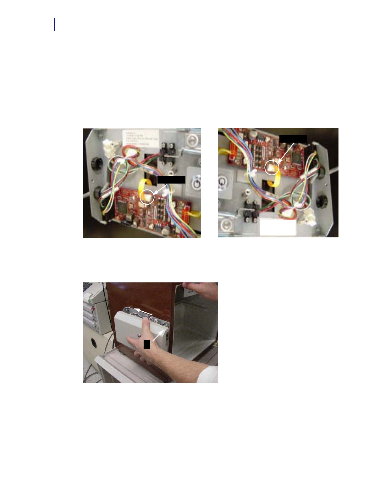
12. Set the S1 slide switch to Not Terminated (not labeled on the board) because the ERB will be in
the middle of the daisy chain configuration. The S2 slide switch should already be set to ERB.
Figure 2-135. Setting the switches
13. Replace the PCB/solenoid metal plate, then tighten the two nuts on either side of the plate,
using a 5/16” nut driver.
14. Close the return door.
15. Close and lock the access door with the cam keys.
16. Proceed to “Software Implementation” on
page 3-1 for software configuration instructions for
FlexLock and TempCheck if installed.
FlexLock Installation and Configuration Guide/60-3002 Rev H © 2011 Omnicell, Inc.
Page 85

Hardware Installation 2-77
Cabling on G4 Cabinets
FlexLock to FlexLock Chain
1. Install the second Flexlock to a refrigerator or cabinet with the same procedures as the first.
2. Remove the Omnicell FlexLock cover plate of the 1st FlexLock using both keys.
Figure 2-136. Moving the key cover plate
3. Remove the 6-32 BH Torx screw.
Figure 2-137. Removing the housing cover screw
© 2011 Omnicell, Inc. FlexLock Installation and Configuration Guide/60-3002 Rev H
Page 86

2-78 Hardware Installation
Cabling on G4 Cabinets
4. Open the refrigerator door, then remove the cover.
Figure 2-138. Removing the housing cover
5. Remove the black Heyco plug from the back of FlexLock #1 (this is adjacent to the black strain
relief located on the power/comm cable). There are small plastic snaps on the inside of plug
at can be pressed with a flat blade screwdriver to release the plug.
th
Figure 2-139. Removing the plug
FlexLock Installation and Configuration Guide/60-3002 Rev H © 2011 Omnicell, Inc.
Page 87

Hardware Installation 2-79
Cabling on G4 Cabinets
6. Route the power/comm cable from FlexLock #2 into the available cutout on FlexLock #1.
Note: Cable limitation from Host to last FlexLock is 125 ft.
Figure 2-140. Routing the Flexlock cable
7. Connect the 6 plug connector into the available white 6 conductor plug.
Figure 2-141. Connecting the FlexLock cable
© 2011 Omnicell, Inc. FlexLock Installation and Configuration Guide/60-3002 Rev H
Page 88

2-80 Hardware Installation
Cabling on G4 Cabinets
8. Install the large black strain relief over the FlexLock #2 power/comm cable.
Figure 2-142. Installing the strain relief
9. Snap the strain relief into the cutout.
Figure 2-143. Snapping the strain relief into the cutout
10. Tie up any loose internal wires with the existing Kurly lock or cable tie.
11. Set the S1 switch to Not Terminated (not marked on PCBA).
Figure 2-144. Checking the PCBA Switch Settings.
FlexLock Installation and Configuration Guide/60-3002 Rev H © 2011 Omnicell, Inc.
Page 89

12. Replace the cover on the first FlexLock and secure it with the 6-32 BH Torx screw.
13. Proceed to “Software Implementation” on page 3-1 for software configuration instructions for
FlexLock and TempCheck if installed.
Retrofit TempCheck
This section provides instructions if retrofitting an existing FlexLock with a TempCheck probe.
The retrofit kit #20-6037 is needed for this procedure.
1. Remove the screw that secures the FlexLock housing cover.
2. Remove the housing cover.
3. Remove the four standoffs that secure the FlexLock inner housing.
4. Follow steps in “TempCheck Installation” on page 2-19.
5. Follow the steps in “Inner Housing and Cover” on page 2-21 using the new inner housing from
the retrofit kit.
6. Proceed to “Software Implementation” on page 3-1 for software configuration instructions for
TempCheck.
Hardware Installation 2-81
Retrofit TempCheck
© 2011 Omnicell, Inc. FlexLock Installation and Configuration Guide/60-3002 Rev H
Page 90

2-82 Hardware Installation
Retrofit TempCheck
FlexLock Installation and Configuration Guide/60-3002 Rev H © 2011 Omnicell, Inc.
Page 91

Software Implementation
This chapter provides general instructions for implementing the FlexLock and its optional
feature, TempCheck. For additional information or assistance, contact Omnicell Technical
Support.
FlexLock
Implementation Overview
Software implementation for FlexLock includes the following:
Bin Addressing
Item Assignment
Reports
FlexLock Programming
Cabinet Configuration
3-1
OmniCenter
Bin Addressing
FlexLock bin addresses are handled essentially the same way that the bin addresses in a
Sure-Med universal compartment are currently treated. The drawer type is FlexLock. The
location displayed is entered by the user at the OmniSupplier. If a user-entered description
is not provided, the field displays Flexlock #1, Flexlock #2, and so on. Like universal
compartment bins, FlexLocks do not support multiple bins, so items that are assigned to a
FlexLock cannot be assigned elsewhere, and vice versa. Only pharmacy items are
supported.
The new Drawer Type information is as follows:
l
Field Value
draw type 46
draw_desc FlexLock
start_bin 0
stop_bin 118
bin_number nBin + 1
subdrawers .F.
multi_bin .F.
matrix .F.
© 2010 Omnicell, Inc. FlexLock Installation and Configuration Guide/H60-3002 Rev H
Page 92

3-2 Software Implementation
FlexLock
Item Assignment
Items can be assigned to existing Remote Lock bins via the OmniCenter Database tab. The
Bin Assignment feature is accessed by selecting the Bins radio button on the Item Record.
Reports
The Pharmacy Drawer Configuration report and the Bin Assignment look-up list are used to
support FlexLock.
Color Touch
FlexLock Programming
1. Login at the Color Touch screen of the cabinet where the FlexLock is cabled.
2. Go to the configuration
a. Press Admin.
b. Press Omni C
onfig.
c. Press Program Fle
3. Press the button on the FlexLock. A confirmation window is displayed when the
FlexLo
ck programming is complete.
Figure 3-1. Pressing the FlexLock button for programming
xLock.
Cabinet Configuration
There are 5 software configurations for FlexLock. Four are maintained by the system. One
can be changed by the user. It is found in the Omni Config, Misc menu.
Misc_Options
Config Name: FlexLock_Timeout_Value
Menu Name: FlexLock Timeout Value
Description: Limit FlexLock access
Val ues :
Default:
Implementation: Set to the desired time out setting in seconds.
0-999 Seconds; 0 seconds = disabled
60 Seconds
FlexLock Installation and Configuration Guide/60-3002 Rev H © 2010 Omnicell, Inc.
Page 93

Note: If the OmniSupplier CountBack Timeout configuration is set to 0 (disabled), the FlexLock
Timeout will also be disabled—regardless of its setting.
TempCheck
Implementation Overview
Implementation for FlexLock TempCheck includes the following:
Setting the Temperature Monitoring Parameters at the OmniCenter
Configuring the cabinet software via Color Touch
FLEXLOCK#_MONITORING
FLEXLOCK#_MONITORFREQ
FLEXLOCK#_LOWTEMPLIMIT
FLEXLOCK#_HIGHTEMPLIMIT
Software Implementation 3-3
TempCheck
OmniCenter
This section provides instructions for setting up the temperature monitoring parameters.
Temperature Monitoring Parameters
1. Login to OmniCenter as Omnicell Tech.
2. Select the Ad
3. Select S
4. Double press T
ministrative tab.
etup Administrative Type.
emperature Monitoring Setup.
Figure 3-2. Administration > Setup window
© 2010 Omnicell, Inc. FlexLock Installation and Configuration Guide/60-3002 Rev H
Page 94

3-4 Software Implementation
TempCheck
5. Select temperature display type (Celsius; Fahrenheit).
6. Select number of months to store temperature readings. The default is
12.
7. Specify notice trigger (only when status changes; all alerts).
8. Check box for notification when status returns to normal if desired.
9. Press Ad
d to specify destinations for alert.
10. Select output type on the Add window.
11. Specify search type, enter a string, then press Search. A matching list is displayed below.
12. Highlight the desired destinations, then press Ad
d.
Figure 3-3. Temperature Monitoring Setup window
13. Repeat Steps 11-12 as needed.
14. Press Clo
15. Press Delet
se when finished adding destinations.
e to remove a destination listing if needed.
FlexLock Installation and Configuration Guide/60-3002 Rev H © 2010 Omnicell, Inc.
Page 95

Color Touch
Software Implementation 3-5
TempCheck
There are four software configurations available if one or more FlexLocks with TempCheck
are connected to the system. The configurations are found in the Omni Config, FlexLock
Temperature Monitoring menu.
Cabinet Software Configuration
FlexTemp
Config Name: FLEXLOCK#_MONITORING
Menu Name: FlexLock # Monitoring
Description: Enables temperature monitoring for the TempCheck device
Val ues :
Default:
Implementation:
On; Off
Off
On to enable temperature monitoring.
Set to
Config Name: FLEXLOCK#_MONITORFREQ
Menu Name: FlexLock # Monitoring Frequency
Description: Specifies the frequency (in minutes) at which the cabinet will check the temperature.
Val ues :
Default:
Implementation: Set the desired number of minutes between each temperature check.
Config Name: FLEXLOCK#_LOWTEMPLIMIT
Menu Name: FlexLock # Low Temp Limit
Description: Specifies the temperature (ºC) below which a low temperature warning will occur.
Val ues :
Default:
Implementation: Set the desired low end of the acceptable temperatur
Config Name: FLEXLOCK#_HIGHTEMPLIMIT
Menu Name: FlexLock # High Temp Limit
Description: Specifies the temperature (ºC) above which a high temperature warning will occur.
Val ues :
Default:
Implementation: Set the desired high end of the acceptable temperature range. Alerts will be given if the sensor
1-120 minutes
30 minutes
-9 to 129º C
2º C
encounters temperatures below this setting.
-8 to 130º C
8º C
ounters temperatures above this setting.
enc
e range. Alerts will be given if the sensor
© 2010 Omnicell, Inc. FlexLock Installation and Configuration Guide/60-3002 Rev H
Page 96

3-6 Software Implementation
TempCheck
FlexLock Installation and Configuration Guide/60-3002 Rev H © 2010 Omnicell, Inc.
Page 97

Service
Product Overview
The FlexLock can be connected to a cabinet or a workstation. It can also be daisy-chained to
an External Return Bin (ERB) or another FlexLock.
The cabinet or workstation acts as a host providing power to the FlexLock directly or
indirectly through a daisy-chained ERB or another FlexLock.
The host cabinet or workstation must be powered down to work on the FlexLock as it does
not have its own power switch. This is true even if the FlexLock to be serviced is in a daisychain and not directly connected to the host cabinet or workstation.
Some services require the disconnection of the FlexLock cables for replacement or to allow
the host equipment to be used while service is being completed on the FlexLock.
4-1
Service Overview
There are four types of services done on a FlexLock. They are listed below with the related
conditions when they are performed.
Alignment Adjustment
This service is done when the refrigerator door does not close properly.
TempCheck Replacement
Replace the TempCheck probe and flex circuit cable (if present) when:
FlexLock Inner Housing Replacement
This service is done when:
Complete FlexLock Replacement
The whole FlexLock assembly is replaced when:
Temperature readings are beyond hardware limit
Voltage problems occur and error messages are displayed
Upgrading an older FlexLock for TempCheck installation
Hardware failure occurs and error messages are displayed
FlexLock has poor adhesion to refrigerator or cabinet
Poor adhesion can be caused by an unclean or textured refrigerator/cabinet surface. It
can also be caused by not waiting long enough for the adhesion to bond before the
FlexLock is used.
Wrong door latch was used originally
© 2010 Omnicell, Inc. FlexLock Installation and Configuration Guide/60-3002 Rev H
Page 98

4-2 Service
Standoffs
#94-6218
Blue Screen
Power Cable
CD
(obsolete)
Alignment
Fixture
TempCheck Probe
#15-7105
Bracket Cutout
AUX assy cables
#94-6138
#94-6233
#94-6158
#91-2052
#91-2051
Service Overview
Tools Required
Kit/Parts Required
Tool Required for
T-10 Torx Driver All Procedures
FlexLock Cam Lock Keys #2202 and #2232 All procedures
ERB Cam Lock Keys #2202 and #2204 Replacing Inner Housing, FlexLock (if connected to ERB)
ESD Wrist Strap All procedures
1/4” Hex Driver (with various bit sizes) Replacing FlexLock
T8 Torx Driver Replacing FlexLock
5/16 Nut Driver Replacing FlexLock
Screwdriver Adjusting alignment
Adhesive Cleaning Tool (safety blade) Replacing TempCheck, FlexLock
Tab le 4-1. Tool s Req uir ed
Figure 4-1. FlexLock Installation Kit #20-6023 with TempCheck probe
FlexLock Installation and Configuration Guide/60-3002 Rev H © 2010 Omnicell, Inc.
Page 99

General Service Instructions
Kits/Parts Used for Description/Notes
#14-7043 Replacing FlexLock Contains Door Brackets, Cam Lock Keys with FlexLock unit/cable
#20-6023 Replacing FlexLock Includes the TempCheck temperature probe, cable for host equipment; See
“Ap pe ndix A Par ts /K it L is t” on page A-1 for details.
#20-6037 Replacing TempCheck,
Inner H
ousing
Tab le 4-2. Kit/Parts Required
Contains the FlexLock inner housing with the TempCheck compatible PCBA
#40-3013 and TempCheck probe; used for upgrading FlexLock for TempCheck
General Service Instructions
These instructions are called by the service procedures that follow.
Service Preparation
These steps are done before every service.
1. Contact the pharmacist so that a representative can be present when pharmacy items are
sible during service.
acces
2. Store the contents of the refrigerator elsewhere. The refrigerator door may be left open
f
or a long period of time depending on the type of service to be done. This could harm
thermal-sensitive medications.
3. Turn off the power to the FlexLock by performing a graceful shut-down the host cabinet
o
r workstation—even if the FlexLock to be serviced is daisy-chained to another FlexLock
or ERB.
4. Wear a properly grounded ESD strap. This will protect sensitive components from
ele
ctro-static discharge.
Service 4-3
FlexLock Manual Override/Cover Plate Removal
These two procedures are usually combined except for alignment adjustment.
FlexLock Manual Override
1. Use cam lock key #2232 to open the FlexLock override cover plate.
Figure 4-2. Unlocking the cover plate
© 2010 Omnicell, Inc. FlexLock Installation and Configuration Guide/60-3002 Rev H
Page 100

4-4 Service
1
2
General Service Instructions
2. Use cam lock key #2202 to override the locking mechanism so that the refrigerator door
can be opened and closed.
Cover Plate Removal
1. Remove the 6-32 BH Torx screw with a T-10 Torx driver.
Cable Procedures
Figure 4-3. Removing the cover plate screw
2. Open the refrigerator door.
3. Slide the cover forward then out.
Figure 4-4. Removing the cover plate
The cable procedures vary by equipment type:
Electronic Sled
PC Box
ERB (as part of daisy-chain)
(another) FlexLock - part of daisy-chain
FlexLock Installation and Configuration Guide/60-3002 Rev H © 2010 Omnicell, Inc.
 Loading...