


 Loading...


 User’sGuide
Shop online at
omega.com e-mail: info@omega.com For latest product manuals: omegamanual.info
OMB-DBK Option Cards and Modules
Part 1 of 2, Through OMB-DBK-34A
OMB-457-0911 rev 8.1

|
OMEGAnet® Online Service |
|
Internet e-mail |
|
|
|
omega.com |
|
info@omega.com |
|
|
|
|
|
|
|
Servicing North America: |
||
U.S.A.: |
One Omega Drive, P.O. Box 4047 |
|
||
ISO 9001 Certified |
Stamford, CT 06907-0047 |
|
||
|
|
TEL: (203) 359-1660 |
FAX: (203) 359-7700 |
|
|
|
e-mail: info@omega.com |
|
|
Canada: |
976 Bergar |
|
||
|
|
Laval (Quebec) H7L 5A1, Canada |
|
|
|
|
TEL: (514) 856-6928 |
FAX: (514) 856-6886 |
|
|
|
e-mail: info@omega.ca |
|
|
For immediate technical or application assistance:
U.S.A. and Canada:
Mexico:
Sales Service: 1-800-826-6342 / 1-800-TC-OMEGA®
Customer Service: 1-800-622-2378 / 1-800-622-BEST®
Engineering Service: 1-800-872-9436 / 1-800-USA-WHEN®
En Espan˜ol: (001) 203-359-7803 |
e-mail: espanol@omega.com |
FAX: (001) 203-359-7807 |
info@omega.com.mx |
Servicing Europe:
Benelux: |
Postbus 8034, 1180 LA Amstelveen, The Netherlands |
|
|
TEL: +31 (0)20 3472121 |
FAX: +31 (0)20 6434643 |
|
Toll Free in Benelux: 0800 0993344 |
|
|
e-mail: sales@omegaeng.nl |
|
Czech Republic: |
Frystatska 184, 733 01 Karviná, Czech Republic |
|
|
TEL: +420 (0)59 6311899 |
FAX: +420 (0)59 6311114 |
|
Toll Free: 0800-1-66342 |
e-mail: info@omegashop.cz |
France: |
11, rue Jacques Cartier, 78280 Guyancourt, France |
|
|
TEL: +33 (0)1 61 37 2900 |
FAX: +33 (0)1 30 57 5427 |
|
Toll Free in France: 0800 466 342 |
|
|
e-mail: sales@omega.fr |
|
Germany/Austria: |
Daimlerstrasse 26, D-75392 Deckenpfronn, Germany |
|
|
TEL: +49 (0)7056 9398-0 |
FAX: +49 (0)7056 9398-29 |
|
Toll Free in Germany: 0800 639 7678 |
|
|
e-mail: info@omega.de |
|
United Kingdom: |
One Omega Drive, River Bend Technology Centre |
|
ISO 9002 Certified |
Northbank, Irlam, Manchester |
|
|
M44 5BD United Kingdom |
|
|
TEL: +44 (0)161 777 6611 |
FAX: +44 (0)161 777 6622 |
|
Toll Free in United Kingdom: 0800-488-488 |
|
|
e-mail: sales@omega.co.uk |
|
It is the policy of OMEGA Engineering, Inc. to comply with all worldwide safety and EMC/EMI regulations that apply. OMEGA is constantly pursuing certification of its products to the European New Approach Directives. OMEGA will add the CE mark to every appropriate device upon certification.
The information contained in this document is believed to be correct, but OMEGA accepts no liability for any errors it contains, and reserves the right to alter specifications without notice.
WARNING: These products are not designed for use in, and should not be used for, human applications.

Warnings, Cautions, Notes, and Tips
Refer all service to qualified personnel. This symbol warns of possible personal injury or equipment damage under noted conditions. Follow all safety standards of professional practice and the recommendations in this manual. Using this equipment in ways other than described in this manual can present serious safety hazards or cause equipment damage.
This warning symbol is used in this manual or on the equipment to warn of possible injury or death from electrical shock under noted conditions.
This ESD caution symbol urges proper handling of equipment or components sensitive to damage from electrostatic discharge. Proper handling guidelines include the use of grounded anti-static mats and wrist straps, ESD-protective bags and cartons, and related procedures.
This symbol indicates the message is important, but is not of a Warning or Caution category. These notes can be of great benefit to the user, and should be read.
In this manual, the book symbol always precedes the words “Reference Note.” This type of note identifies the location of additional information that may prove helpful. References may be made to other chapters or other documentation.
Tips provide advice that may save time during a procedure, or help to clarify an issue. Tips may include additional reference.
Specifications and Calibration
Specifications are subject to change without notice. Significant changes will be addressed in an addendum or revision to the manual. As applicable, we calibrate our hardware to published specifications. Periodic hardware calibration is not covered under the warranty and must be performed by qualified personnel as specified in this manual. Improper calibration procedures may void the warranty.
iii

Your order was carefully inspected prior to shipment. When you receive your order, carefully unpack all items from the shipping carton and check for physical signs of damage that may have occurred during shipment. Promptly report any damage to the shipping agent and your sales representative. Retain all shipping materials in case the unit needs returned to the factory.
CAUTION
Using this equipment in ways other than described in this manual can cause personal injury or equipment damage. Before setting up and using your equipment, you should read all documentation that covers your system. Pay special attention to Warnings and Cautions.
Note: During software installation, Adobe® PDF versions of user manuals will automatically install onto your hard drive as a part of product support. The default location is in the Programs group, which can be accessed from the Windows Desktop. Initial navigation is as follows:
Start [Desktop “Start” pull-down menu]
Programs
Omega DaqX Software
You can also access the PDF documents directly from the data acquisition CD by using the <View PDFs> button located on the opening screen.
Refer to the PDF documentation for details regarding both hardware and software.
A copy of the Adobe Acrobat Reader® is included on your CD. The Reader provides a means of reading and printing the PDF documents. Note that hardcopy versions of the manuals can be ordered from the factory.
iv
Part 1 of 2
DBK Options
General Information through DBK34A
© 1998 through 2005 |
917594 Part 1 of 2 |
Printed in the United States of America |

ii

Manual Layout
This user’s manual includes several chapters and independent DBK sections. It also includes DBK Basics, which is a stand alone document.
DBK Basics – Explains what DBKs are and uses tables to identify the various types of DBKs. The document module includes: tips for setting up a data acquisition system, how to determine system power requirements, and various power options.
Chapters*
1 – Signal Management. Discusses signal management and signal conditioning, and CE compliance information.
2 – System Connections and Pinouts. Provides instructions for connecting a DBK option to a Daq or LogBook device. Pinouts are included for the P1, P2, and P3 DB37 connectors, as well as the 100-pin P4 connector used by /2000 Series Devices.
3 – DBK Set Up in DaqView. Provides instruction for setting up analog and digital DBKs in
DaqView’s Hardware Configuration screen.
4 – DBK Set Up in LogView. Provides instruction for setting up analog and digital DBKs in
LogView’s Hardware Configuration window.
5 – Troubleshooting. Explains solutions to common noise, wiring, and configuration problems.
Dimensional Drawings
DBK Cards and Modules** – Independent DBK documentation is provided in alphanumeric order on a DBK by DBK basis. Refer to the Table of Contents for a complete list.
Documentation for discontinued DBKs [listed at the end of the Table of Contents] is not included in the DBK Options Manual, but can be downloaded or read from our website.
Note: During software installation, Adobe® PDF versions of user manuals will automatically install onto your hard drive as a part of product support. The default location is in the Programs group, which can be accessed from the Windows Desktop. Refer to the PDF documentation for details regarding both hardware and software.
A copy of the Adobe Acrobat Reader® is included on your CD. The Reader provides a means of reading and printing the PDF documents. Note that hardcopy versions of the manuals can be ordered from the factory.
Note that you can access PDF documents directly from the data acquisition CD via the <View PDFs> button located on the CD’s opening screen.
*The chapters are included in Part 1 of the DBK Options Manual. DBKs up to and including DBK34A are also included in Part 1.
**Part 2 of the manual begins with DBK41.
DBK Option Cards & Modules User’s Manual |
917094 |
v |

Table of Contents
DBK Basics
Introduction…… DBK Basics-1
How Do DBKs Connect? …… DBK Basics- 2 DBK Identification Tables ….. DBK Basics-9
Tips on Setting up a Data Acquisition System …… DBK Basics-12
Power Supplies & Connectors …… DBK Basics-14
An Introduction to Power-Related DBKs …… DBK Basics-15
Power Requirements...... DBK Basics-16
Calculating Your System’s Power Needs …… DBK Basics-18
Additional Reading ….. DBK Basics-21
1 - Signal Management
Signal Modes ...... |
1-1 |
|
|
|
|
System Noise |
...... 1-5 |
|
|
|
|
Using DBK Cards and Modules for Signal |
|||||
Conditioning ...... |
1-6 |
|
|
|
|
Channel Control and Expansion |
...... 1-7 |
||||
Signal Acquisition ...... |
1-9 |
|
|
|
|
Sequencer ...... |
1-9 |
|
|
|
|
Scan Rate ...... |
1-10 |
|
|
|
|
Triggering ...... |
1-10 |
|
|
|
|
Counter/Timer Functions ...... |
1-11 |
|
|||
Simultaneous Sample and Hold (SSH) ...... |
1-11 |
||||
Two-Point Calibration of a Temperature |
|||||
Measurement System ...... |
1-12 |
|
|
||
Overview ...... |
1-12 |
|
|
|
|
An Example of Two-Point Calibration ...... |
1-13 |
||||
Calculation of Scale and Offset ...... |
1-14 |
|
|||
Implementing the Scale and Offset Constants in |
|||||
DaqView ...... |
1-14 |
|
|
|
|
Converting Degrees from Celsius to |
|
||||
Fahrenheit ...... |
1-14 |
|
|
|
|
One Known Temperature Environment ...... |
1-15 |
||||
Use of a Temperature Calibrator ...... |
1-15 |
||||
CE Compliance |
...... 1-15 |
|
|
|
|
CE Standards and Directives ...... |
1-16 |
|
|||
Safety Conditions ...... |
1-16 |
|
|
|
|
Emissions/Immunity Conditions ...... |
1-17 |
|
|||
CE Enhancements for Existing Products ...... |
1-17 |
||||
2 – System Connections and Pinouts
Overview …… 2-1
P1 – DB37 for Analog I/O …… 2-3 P2 – DB37 for Digital I/O …… 2-4
P3 – DB37 for Pulse/Frequency/High-Speed Digital I/O …… 2-5
P4 to P1, P2, P3 Correlation …… 2-6 Ground Tables – P4 to P1, P2, P3 …… 2-9
3 – DBK Set Up in DaqView
Overview …… 3-1
Setting Up Analog DBKs …… 3-5
Setting Up Digital DBKs …… 3-7
Setting Internal Clock Speed to 100 kHz …3-9
4 – DBK Set Up in LogView
Overview …… 4-1
Setting Up Analog DBKs …… 4-4
Setting Up Digital DBKs …… 4-7
5 – Troubleshooting
ESD Handling Notice …… 5-1
Troubleshooting Checklist……5-1
Frequently Asked Questions ……5-3
Customer Assistance……5-6
Dimensional Drawings
DBK Documents
DBK1, 16-Connector BNC Adapter Module
DBK2, 4-Channel Voltage Output Card
DBK4, 2-Channel Dynamic Signal Input Card
DBK5, 4-Channel Current Output Card
DBK7, 4-Ch. Frequency-To-Voltage Input Card
DBK8, 8-Channel High-Voltage Input Card
DBK9, 8-Channel RTD Card
DBK10, 3-Slot Expansion Chassis
DBK11A, Screw-Terminal & BNC Option Card
DBK15, Universal Current, Voltage Input Card
DBK16, 2-Channel Strain-Gage Card
DBK17, 4-Channel Simultaneous Sample and
Hold Card
DBK18, 4-Channel, Low-Pass Filter Card
DBK20 and DBK21, Digital I/O Cards
DBK23, Isolated Digital Input Chassis
DBK24, Isolated Digital Output Chassis
DBK25, 8-Channel Relay Output Card
DBK30A, Rechargeable Battery Module
DBK32A, Auxiliary Power Supply Card
DBK34A, UPS / Battery Module
vi |
917094 |
DBK Option Cards & Modules User’s Manual |

Part 2
DBK41, 10-Slot Expansion Module
DBK42, 16-Slot 5B Signal Conditioning Module DBK43A, 8-Channel Strain-Gage Module DBK44, 2-Ch. 5B Signal-Conditioning Card DBK45, 4-Ch. SSH and Low-Pass Filter Card DBK46, 4-Channel Analog Output Card
DBK48, Multipurpose Isolated SignalConditioning Module (supports up to 16 8B Modules)
DBK50 and DBK51, Voltage Input Modules
DBK55, 8-Channel Frequency-to-Voltage Input Module
DBK60, 3-Slot Expansion Chassis
DBK65, 8-Channel Transducer Interface Module
DBK70, Vehicle Network Interface, Analog Multiplexer Module (see p/n 1056-0901)
DBK80, 16-Ch. Differential Voltage Input Card with Excitation Output
DBK81, 7-Ch. T/C Card
DBK82, 14-Ch. T/C Card
DBK83, 14-Ch. T/C Card, uses external connection pod
DBK84, 14-Ch. T/C Module
DBK85, 16-Ch. Differential Voltage Module DBK90, 56-Ch. T/C Module
DBK100 Series, (DBK100/D, 100/T,101) In-Vehicle Thermocouple Measurement System
DBK200 Series Matrix
DBK200, P4-to-P1 Adapter Board
DBK202, DBK203, DBK204 Series
P4-to-P1/P2/P3 Adapters
DBK206, P4-to-P1/P2/P3 Adapter Board with Screw Terminals
DBK207 and DBK207/CJC, 16-Channel, 5B Carrier Boards
DBK208, Relay Carrier Board, Opto-22 Compatible
DBK209, P4 to P1/P2/P3 Mini-Adapter Board DBK210, 32-Ch. Digital I/O Carrier Board
DBK213, Screw-Terminal & Expansion Module 3-Card Slot, P1/P2/P3/P4 Compatibility
DBK214, 16-Connector BNC Interface Module P1/P2/P3/P4 Compatibility
DBK215, 16-Connector BNC Connection Module with 68-Pin SCSI Adaptability
DBK601 thru DBK609, Termination Panels
Discontinued DBKs
The following DBKs have been discontinued. However, you may contact the factory if you need documentation for these devices.
DBK12 and DBK13, A/I Multiplexer Cards DBK19, 14-Channel Thermocouple Card DBK33, Triple-Output Power Supply Card DBK34, Vehicle UPS Module
DBK40, 18-Connector BNC Analog Interface DBK52, 14-Ch. Thermocouple Input Module
DBK53 and DBK54, Analog Multiplexing Modules
DBK201, P4-to-P1/P2/P3 Adapter Board DBK603, Termination Panel, Safety Jacks, SE DBK605-B, Termination Panel, T/C, B Type, DE DBK605-R, Termination Panel, T/C, R Type, DE DBK605-S, Termination Panel, T/C, S Type, DE DBK605-U, Termination Panel, T/C, U Type, DE DBK609, Termination Panel, 5-Pin DIN
DBK Option Cards and Modules User’s Manual |
917094 |
vii |

This page is intentionally blank.
viii |
917594 |
DBK Option Cards & Modules User’s Manual |
DBK Basics
This “DBK Basics” section of the manual does not apply to DaqBoard/500 Series or DaqBoard/1000 Series boards. Those boards are not intended for use with DBK options; nor will they support such options.
Introduction…… 1
How Do DBKs Connect to the Data Acquisition Device? …… 2
Connecting DBKs to DaqBook/100/200 Series Devices, ISA-Type DaqBoards, & LogBooks … 2 Connecting DBKs to Daq PC-Cards ……3
Connecting DBKs to DaqBoard/2000 Series Boards …… 4 Connecting DBKs to DaqBook/2000 Series Devices …… 5
DBK Identification Tables ….. 9
Analog Output DBKs …… 9 Digital I/O Control DBKs …… 9
Analog Signal Conditioning DBKs …… 9
Expansion and Terminal Panel Connection DBKs …… 10 Power Supply DBKs …… 12
Tips on Setting up a Data Acquisition System …… 12 Power Supplies and Power Connectors ……14
An Introduction to Power-Related DBKs ….. 15 Power Requirements …… 16
Calculating Your System’s Power Needs …… 18 Additional Reading ….. 21
CAUTION
Turn off power to all devices connected to the system before connecting cables or setting configuration jumpers and switches. Electrical shock or damage to equipment can result even under low-voltage conditions.
CAUTION
The discharge of static electricity can damage some electronic components. Semiconductor devices are especially susceptible to ESD damage. You should always handle components carefully, and you should never touch connector pins or circuit components unless you are following ESD guidelines in an appropriate ESD controlled area. Such guidelines include the use of properly grounded mats and wrist straps, ESD bags and cartons, and related procedures.
Introduction
The term “DBK” typically refers to a card or module that is used to expand or enhance a primary data acquisition device, such as a DaqBook, DaqBoard, or LogBook. As will be seen in the upcoming DBK identification tables, DBKs provide a wide variety of data acquisition functions. Depending on the DBKs used, one or more of the following can be realized:
•signal conditioning
•analog output
•digital I/O
•channel expansion
•supplying powering to another acquisition device
•providing an interface for different connectivity; for example, in a DaqBoard/2000 Series board, converting a P4, 100-pin connector to P1, P2, and P3 37-pin, DB37 connectors.
Daq Systems |
886995 |
DBK Basics, pg. 1 |
Reference Notes: During software installation, Adobe® PDF versions of user manuals will automatically install onto your hard drive as a part of product support. The default location is in the Programs group, which can be accessed from the Windows Desktop. Refer to the PDF documentation, especially the DBK Option Cards and Modules User’s Manual
(p/n 457-0905) for details regarding both hardware and software in relevant to DBKs.
A copy of the Adobe Acrobat Reader® is included on your CD. The Acrobat Reader provides a means of reading and printing the PDF documents. Note that hardcopy versions of the manuals can be ordered from the factory.
How Do DBKs Connect to the Data Acquisition Device?
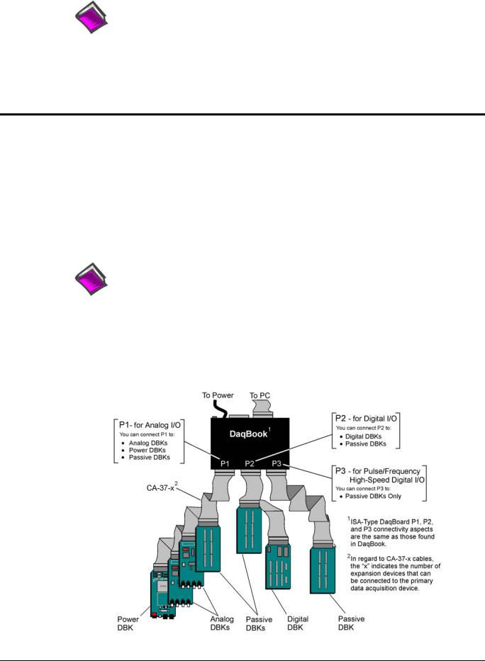
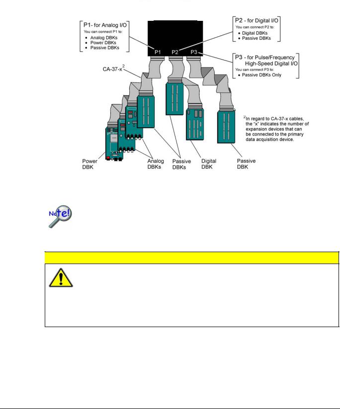
Each DBK connects to the primary data acquisition device; e.g., a DaqBook, DaqBoard, or LogBook, through one of three 37-pin ports, which are designated as follows:
•P1 – Analog I/O
•P2 – Digital I/O
•P3 – Pulse/Frequency/High-Speed Digital I/O
Depending on the primary data acquisition device, connectivity issues differ slightly. This will be made clear by the figures and accompanying text that follow.
Connecting DBKs to DaqBook/100/200 Series Devices, ISA-Type DaqBoards, & LogBooks
Reference Notes:
o DaqBoard/2000 Series and /2000c Series users, refer to page 4. o DaqBook/2000 Series users, refer to page 5.
For DaqBook/100 Series and DaqBook/200 Series devices, ISA-Type DaqBoards, and LogBooks, DBK connections are not made directly to the port, but through a CA-37-x ribbon cable, where “x” indicates the number of expansion devices that can be connected. For example, in addition to providing a DB37 connector to interface with the primary data acquisition device, a CA-37-3 cable includes three additional DB37 connectors. These provide a means of adding three DBKs to one port. Use of a CA-37-16 cable will allow up to 16 DBKs to be added. The CA-37-x cable system is excellent for DaqBooks, LogBooks, and ISA-type DaqBoards.
/100 /200 Series
Connecting DBKs to a DaqBook/100 Series or /200 Series Device
pg. 2, DBK Basics |
967794 |
Daq Systems |
The previous figure applies to LogBooks, DaqBook/100/200 Series devices, and ISA-type DaqBoards. As will be seen elsewhere in this document, some devices do not include all three connectors, i.e., P1, P2, and P3.
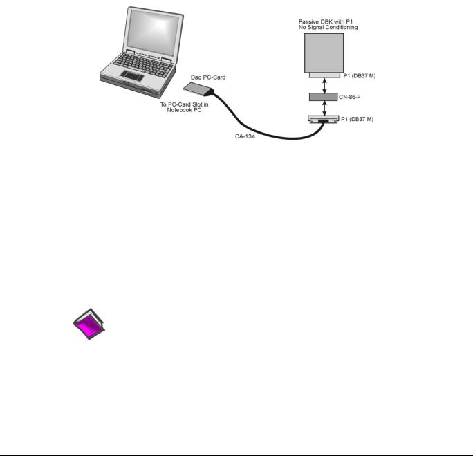
Connecting DBKs to Daq PC-Cards
The Daq PC-Card is only intended for connections to a P1 connector of a single “passive” DBK card or module. A passive DBK card or module is one that provides a desired connectivity (such as BNCs or screw terminals), but performs no signal conditioning.
A CA-134 Interface Cable and a CN-86-F (dual DB37 female adapter) are used to provide the DB37, P1 connector.
Daq PC-Card Cabling
The CA-134 cable connects to a CN-86-F adapter, which then connects to a single “passive” card or module. The passive DBKs are:
•DBK1 – 16 Connector BNC Module
•DBK11A – Screw Terminal Option Card
•DBK40 – BNC Analog Interface
Reference Note:
For information regarding the passive DBKs (DBK1, DBK11A, and DBK40), refer to the DBK Option Cards and Modules User’s Manual (p/n 457-0905).
Daq Systems |
967794 |
DBK Basics, pg. 3 |
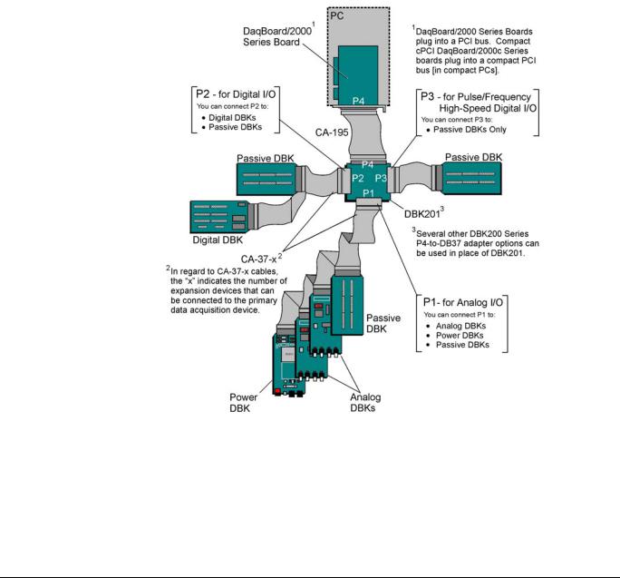
Connecting DBKs to DaqBoard/2000 Series Boards
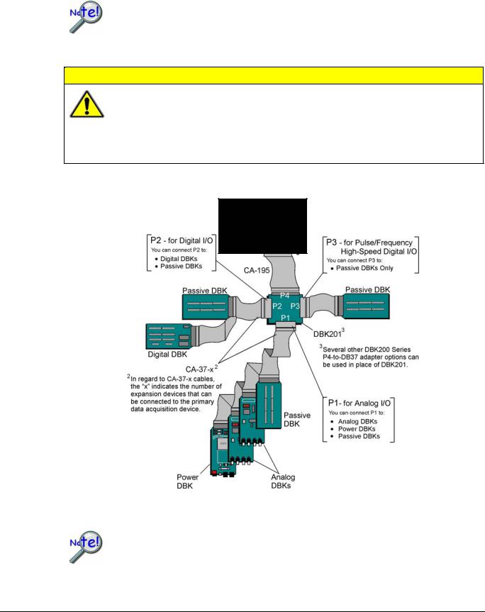
DaqBoard/2000 Series and cPCI DaqBoard/2000 Series boards have 100-pin connectors designated as P4. The 100 pins correlate to various pins on P1, P2, and P3 DB37 connectors.* Connectivity in the system is as follows (see figure).
•Both the DaqBoard/2000 and /2000c Series board connect to a CA-195 cable. The cable has two, 100-pin, P4 connectors.
•The CA-195 connects to a DBK200 Series adapter board or adapter module for 100-pin to 37-pin adaptations, e.g., P4-to-P1, P2, P3; but not necessarily all three.*
•The DBK200 Series adapter connects to a CA-37-x ribbon cable, where “x” indicates the number of expansion devices that can be connected. For example, in addition to providing a DB37 connector to interface with the primary data acquisition device, a CA-37-3 cable includes three additional DB37 connectors. These provide a means of adding three DBKs to one port. Use of a CA-37-16 cable will allow up to 16 DBKs to be added.
•The CA-37-x cable connects to expansion DBKs, in accordance with port type. For example, Analog DBKs to port P1, Digital DBKs to port P2, and passive DBKs to port P3.
Connecting DBKs to a DaqBoard/2000 Series Board
* DaqBoard/2003 and cPCI DaqBoard/2003c are exceptions to the above connectivity method. The /2003 board typically connects directly to a DBK205 (P4-to-Screw Terminal Adapter), as discussed in the DBK Option Cards and Modules User’s Manual (p/n 457-0905).
Note: DaqBook/2000 Series Devices, which are discussed in the following section, can also connect to DBKs via a P4 connector, as indicated in the above figure.
pg. 4, DBK Basics |
967794 |
Daq Systems |
Connecting DBKs to DaqBook/2000 Series Devices
Several products make use of the DaqBook/2000 nomenclature. However, they do not all offer the same connection options. Refer to pinouts for the specific devices, as needed.
Product |
Connects to DBK Expansions via … |
|
|
DaqBook/2001 and /2005 |
37-pin connectors P1, P2, and P3. There is no P4. |
|
|
DaqBook/2020 |
37-pin connectors P1 and P2. There is no P3 or P4. |
|
|
DaqOEM/2001 and /2005 |
40-pin headers (JP1, JP2, and JP3). There is no P4. |
|
|
DaqBook/2000A |
37-pin connectors P1, P2, P3, and a 100-pin P4 connector. |
|
|
DaqBook/2000E |
37-pin connectors P1, P2, P3, and a 100-pin P4 connector. |
|
|
DaqBook/2000X |
37-pin connectors P1, P2, P3, and a 100-pin P4 connector. |
|
|
For DaqBook/2000 Series devices, DBK connections can be made to Ports P1, P2, and/or P3 (when applicable). For the “AEX” models a 100-pin P4 connector can be used. A discussion of both methods, follows.
The P4 connector on a DaqBook/2000 “AEX” device shares signal connections with the
P1, P2, and P3 connectors. P4 offers no additional I/O. Connecting a DBK200 Series
Option to P4 via a CA-195 cable distances the P1, P2, P3 connection from the
DaqBook/2000 Series device. It does not provide any new signal I/O. See the following
Caution.
CAUTION
Signal conflicts between a DaqBook/2000 “AEX” device’s P1, P2, P3 connectors and its P4 connector can result in erroneous readings and possible equipment damage.
Therefore, when connections have been made to P1, P2, and/or P3, use caution when making connections through P4, and visa versa.
Refer to P1, P2, P3, and P4 pinouts to avoid making duplicate signal connections.
There are two ways to connect a DBK option to a DaqBook/2000 “AEX” device. The first method is preferable, as it introduces less noise.
Preferred Method – (a) Connect a CA-37-x cable to the appropriate DB37 connector [P1, P2, or P3] on the DaqBook/2000 Series device. (b) Connect the free end of the cable to the DBK card or module.
Optional Method – (a) Connect a CA-195-x cable to the P4 connector on the DaqBook/2000 Series device. (b) Connect the free end of the cable to a DBK200 Series device. (c) Connect the DBK option to the DBK200 Series device, as applicable.
The primary reason that less noise is seen in the “preferred” method is that a DaqBook/2000 Series device’s P1 connector pertains only to analog acquisition signals and the P2 connector pertains only to digital I/O. This provides a strong degree of isolation between the two signal types. However, in the case of a CA-195-x cable connected to P4, digital and analog signals co-exist in one cable.
If you need to use the P4 connection method, use of the 8-inch ribbon cable (CA-195-1) will result in the lowest level of crosstalk [for that method].
Daq Systems |
967794 |
DBK Basics, pg. 5 |
Connecting DBKs to a DaqBook/2000 Series Device via P1, P2, and/or P3
The DBKs do not connect directly to the port, but through a CA-37-x ribbon cable, where “x” indicates the number of expansion devices that can be connected. For example, a CA-37-3 cable includes a 37-pin mating connector to interface with the DaqBook/2000 Series DB37 connector (P1, P2, P3); it also includes three additional DB37 connectors. These provide a means of adding three DBKs to one port. Use of a
CA-37-16 cable will allow up to 16 DBKs to be added to one DaqBook/2000 Series device DB37-type port.
DaqBook/2000
Series Device
Connecting DBKs to a DaqBook/2000 Series Device via P1, P2, and P3
The P4 connector on a DaqBook/2000 “AEX” device shares signal connections with the P1, P2, and P3 connectors. P4 offers no additional I/O. Connecting a DBK200 Series Option to P4 via a CA-195 cable distances the P1, P2, P3 connection from the DaqBook/2000 Series device. It does not provide any new signal I/O. See the following Caution.
CAUTION
Signal conflicts between a DaqBook/2000 “AEX” device’s P1, P2, P3 connectors and its P4 connector can result in erroneous readings and possible equipment damage.
Therefore, when connections have been made to P1, P2, and/or P3, use caution when making connections through P4, and visa versa.
The following pinouts indicate the P1, P2, and P3 pins, and their P4 equivalents. Use the pinouts to avoid making duplicate signal connections.
pg. 6, DBK Basics |
967794 |
Daq Systems |
Connecting DBKs to a DaqBook/2000 “AEX” Device via P4
Every DaqBook/2000 “AEX” device has a 100-pin connector designated as P4. The P4 pins correlate to various pins on P1, P2, and P3.
The P4 connector on a DaqBook/2000 “AEX” device shares signal connections with the P1, P2, and P3 connectors. P4 offers no additional I/O. Connecting a DBK200 Series Option to P4 via a CA-195 cable distances the P1, P2, P3 connection from the DaqBook/2000 “AEX” device. It does not provide any new signal I/O. See the following Caution.
CAUTION
Signal conflicts between a DaqBook/2000 AEX device’s P1, P2, P3 connectors and its P4 connector can result in erroneous readings and possible equipment damage.
Therefore, when connections have been made to P1, P2, and/or P3, use caution when making connections through P4, and visa versa.
Refer to P1, P2, P3, and P4 pinouts to avoid making duplicate signal connections.
A brief explanation of P4 connectivity for DaqBook/2000 AEX devices follows the illustration.
DaqBook/2000
Series Device
P4
Connecting DBKs to a DaqBook/2000 AEX Device via P4
DaqBook/2001, DaqBook/2005, DaqOEM/2001, DaqOEM/2005, and DaqBook/2020 do not have a P4 connector. The P4 connection option applies to “AEX” models only.
Daq Systems |
967794 |
DBK Basics, pg. 7 |
P4 connectivity for DaqBook/2000 “AEX” devices is as follows:
•One end of a CA-195 cable connects to the DaqBook/2000 “AEX” device’s 100-pin P4 connector. Note that the CA-195 cable has two P4 connectors.
•The other end of the CA-195 cable connects to a DBK200 Series adapter board [or adapter module] for 100-pin to 37-pin adaptations, e.g., P4-to-P1, P2, P3; but not necessarily all three.
•The DBK200 Series adapter connects to one or more CA-37-x ribbon cables, where “x” indicates the number of expansion devices that can be connected. For example, in addition to providing a DB37 connector to interface with the primary data acquisition device, a CA-37-3 cable includes three additional DB37 connectors. These provide a means of adding three DBKs to one port. Use of a CA-37-16 cable will allow up to 16 DBKs to be added.
•The CA-37-x cable connects to expansion DBKs, in accordance with port type. For example, Analog DBKs to port P1, Digital DBKs to port P2, and passive DBKs to port P3.
There are two ways to connect a DBK option to a DaqBook/2000 “AEX” device. The first method is preferable, as it introduces less noise.
Preferred Method – (a) Connect a CA-37-x cable to the appropriate DB37 connector [P1, P2, or P3] on the DaqBook/2000 Series device. (b) Connect the free end of the cable to the DBK card or module.
Optional Method – (a) Connect a CA-195-x cable to the P4 connector on the DaqBook/2000 Series device. (b) Connect the free end of the cable to a DBK200 Series device. (c) Connect the DBK option to the DBK200 Series device, as applicable.
The primary reason that less noise is seen in the “preferred” method is that a DaqBook/2000 “AEX” device’s P1 connector pertains only to analog acquisition signals and the P2 connector pertains only to digital I/O. This provides a strong degree of isolation between the two signal types. However, in the case of a CA-195-x cable connected to P4, digital and analog signals co-exist in one cable.
If you need to use the P4 connection method, use of the 8-inch ribbon cable (CA-195-1) will result in the lowest level of crosstalk [for that method].
The CE Cable Kit, p/n CA-209D, may be required for systems that require a P4 cable length of 3 feet. The CA-209D kit includes a shielded version of the CA-195 cable, two grounding pigtails, and associated cable clamps. When properly connected, the shielded cable provides greater immunity to noise. The CE Compliance chapter includes details.
pg. 8, DBK Basics |
967794 |
Daq Systems |

DBK Identification Tables
Analog Output DBKs
Analog Output
Product |
Name/Description |
I/O |
Connects To: |
DBK2 |
Voltage Output Card |
4 channels |
P1 |
DBK5 |
Current Output Card |
4 channels |
P1 |
DBK46 |
Analog Output Card option for designated devices |
4 channels |
Internal |
|
|
|
PC Board |
Digital I/O Control DBKs
Digital I/O / Control
Product |
|
Name/Description |
I/O |
|
Connects To: |
|
DBK20 |
|
General-Purpose Digital I/O Card (Screw Terminals) |
48 channels |
|
P2 |
|
DBK21 |
|
General-Purpose Digital I/O Card (DB37 Connectors) |
48 channels |
|
P2 |
|
DBK23 |
|
Optically Isolated Digital-Input Module |
24 channels |
|
P2 |
|
DBK24 |
|
Optically Isolated Digital-Output Module |
24 channels |
|
P2 |
|
DBK25 |
|
Relay Output Card |
8 channels |
|
P2 |
|
DBK208 |
|
Carrier board for Opto-22 Compatible SSR Digital Modules. |
16 Channels |
|
P2 or P4 |
|
DBK210 |
|
Carrier Board for Grayhill 70M-Series Mini-Modules |
32 Channels |
|
P2 or P4, P1 exp. |
|
|
|
o P1, P2, and P3 DB37 connectors do not exist on the DaqBoard/2000 Series boards or /2000c |
||||
Notes |
|
|||||
|
|
|
Series boards, but are obtained by using P4 adapters (DBK200 series boards). |
|
||
oFor DaqBoard/2000 Series devices, unless otherwise noted, the internal clocks should be set to 100 kHz when used with any of the following DBK options: DBK12, DBK13, DBK15, DBK19, DBK52, DBK53, and DBK54. See specific DBK section for details.
o DaqBoard/500 Series boards do not support DBK options. o DaqBoard/1000 Series boards do not support DBK options.
o DaqBook/2000 “AEX” devices have P1, P2, and P3 connectors and, in addition a P4 connector.
Daq Systems |
967794 |
DBK Basics, pg. 9 |

Analog Signal Conditioning DBKs
The DBKs that are used for analog signal conditioning attach to transducers and condition their outputs into analog voltages. An A/D converter, located in the primary acquisition device, measures the analog voltages. There are many signal-conditioning solutions available (and more are in development). Note that DBK high-capacity modules require more circuitry than can fit on a compact card.
Analog Signal Conditioning |
|
|
|
|
|
Product |
Name/Description |
|
I/O |
|
Connects To: |
DBK4 |
Dynamic Signal Input Card |
|
2 channels |
|
P1 |
DBK7 |
Frequency-to-Voltage Input Card |
|
4 channels |
|
P1 |
DBK8 |
High-Voltage Input Card |
|
8 channels |
|
P1 |
DBK9 |
RTD Measurement Card |
|
8 channels |
|
P1 |
DBK12 |
Low-Gain Analog Multiplexing Card |
See note 2 |
16 channels |
|
P1 |
DBK13 |
High-Gain Analog Multiplexing Card |
See note 2 |
16 channels |
|
P1 |
DBK15 |
Universal Current/Voltage Input Card |
See note 2 |
16 channels |
|
P1 |
DBK16 |
Strain-Gage Measurement Card |
|
2 channels |
|
P1 |
DBK17 |
Simultaneous Sample & Hold Card |
|
4 channels |
|
P1 |
DBK18 |
Low-Pass Filter Card |
|
4 channels |
|
P1 |
DBK19 |
Thermocouple Card |
See note 2 |
14 channels |
|
P1 |
DBK42 |
5B Isolated Signal-Conditioning Module |
|
16 channels |
|
P1 |
DBK43A |
Strain-Gage Measurement Module |
|
8 channels |
|
P1 |
DBK44 |
5B Isolated Signal-Conditioning Card |
|
2 channels |
|
P1 |
DBK45 |
SSH and Low-Pass Filter Card |
|
4 channels |
|
P1 |
DBK48 |
8B Isolated Signal-Conditioning Module |
|
16 channels |
|
P1 |
DBK50 |
Isolated High-Voltage Input Module |
|
8 channels |
|
P1 |
DBK51 |
Isolated Low-Voltage Input Module |
|
8 channels |
|
P1 |
DBK52 |
Thermocouple Input Module |
See note 2 |
14 channels |
|
P1 |
DBK53 |
Low-Gain Analog Multiplexing Module |
See note 2 |
16 channels |
|
P1 |
DBK54 |
High-Gain Analog Multiplexing Module |
See note 2 |
16 channels |
|
P1 |
DBK55 |
Frequency to Voltage Module |
|
8 channels |
|
P1 |
DBK65 |
Channel Transducer Interface Module |
|
8 channels |
|
P1 |
DBK70 |
Vehicle Network Interface, Analog Multiplexer Module |
16 channels |
|
P1 |
|
DBK80 |
Differential Voltage Input Card with Excitation Output |
16 channels |
|
P1 |
|
DBK81 |
Thermocouple Card, High-Accuracy |
|
7 channels |
|
P1 |
DBK82 |
Thermocouple Card, High-Accuracy |
|
14 channels |
|
P1 |
DBK83 |
Thermal Couple Card, High-Accuracy; uses Connection Pod |
14 channels |
|
P1 |
|
DBK84 |
Thermocouple Module, High-Accuracy |
|
14 channels |
|
P1 |
DBK85 |
Differential Voltage Module |
|
16 channels |
|
P1 |
DBK90 |
Thermocouple Module, High-Accuracy |
|
56 channels |
|
P1 |
DBK207 |
Carrier Board for 5B Compatible Analog Input Modules |
16 channels |
|
P1 or P4 |
|
DBK207/CJC |
Carrier Board for 5B Compatible Analog Input Modules. |
16 channels |
|
P1 or P4 |
|
|
DBK207/CJC includes cold junction compensation (CJC) |
|
|
|
|
Notes |
o P1, P2, and P3 DB37 connectors do not exist on the DaqBoard/2000 Series boards or /2000c |
||||
|
Series boards, but are obtained by using P4 adapters (DBK200 series boards). |
|
|||
oFor DaqBoard/2000 Series devices, unless otherwise noted, the internal clocks should be set to 100 kHz when used with any of the following DBK options: DBK12, DBK13, DBK15, DBK19, DBK52, DBK53, and DBK54. See specific DBK section for details.
o DaqBoard/500 Series boards do not support DBK options. o DaqBoard/1000 Series boards do not support DBK options.
o DaqBook/2000 “AEX” devices have P1, P2, and P3 connectors and, in addition a P4 connector.
pg. 10, DBK Basics |
967794 |
Daq Systems |
Expansion and Terminal Panel Connection DBKs
The following DBKs offer provide various expansion and connection options. The stackable 3-slot DBK10 low-profile enclosure can be used for up to three DBKs. If a system has more than 3 DBKs, the 10-slot DBK41 can be used. Several DBK41s can be daisy-chained to accommodate many DBKs in one system.
Expansion and Connection, General
Product |
Name/Description |
I/O |
Connects To: |
DBK1 |
16-Connector BNC Adapter Module |
16 connectors |
P1 |
DBK10 |
3-Slot Expansion Chassis |
3 cards |
P1, P2, or P3 |
DBK11A |
Screw-Terminal Option Card (DB37-Screw Terminal Block) |
Component |
P1, P2, or P3 |
|
|
sockets |
|
DBK40 |
BNC Interface |
18 connectors |
P1 |
DBK41 |
Analog Expansion Enclosure |
10 cards |
P1 |
DBK60 |
Expansion Chassis with Termination Panels |
3 cards |
P1 or P2 |
Termination Panels, Connectivity for DaqBoard/260
Product |
Name/Description |
I/O |
Connects To: |
DBK601 |
Termination Panel - Blank rear panel |
none |
N/A |
DBK602 |
Termination Panel - BNC rear panel |
16 connectors |
DBK Card |
DBK603 |
Termination Panel - Safety Jacks, single ended |
16 connectors |
DBK Card |
DBK604 |
Termination Panel - Safety Jacks, differential |
8 differential (16) |
DBK Card |
DBK605 |
Termination Panels - Thermocouple, differential panels; |
16 differential |
DBK Card |
|
specify type: B, J, K, R, S, or T |
|
|
DBK606 |
Termination Panel – 3 Terminal Blocks; 16 connections per TB |
48 connectors |
DBK Card |
DBK607 |
Termination Panel – strain relief clamp |
none |
N/A |
DBK608 |
Termination Panel – 3 female DB37 connectors |
three DB37 |
DBK Card |
Several signal connection options were developed primarily for use with DaqBoard/2000 Series and cPCI DaqBoard/2000c Series Boards. The DBK200 Series P4-Adapter documentation provides the basic
connection concepts. That information, along with the related DBK subsections should enable you to set up your desired configuration.
Connection Interface Boards and Modules
Product |
Description |
I/O |
|
Connects To: |
DBK200 |
P4-to-P1 Adapter Board |
P1 |
|
P4 |
DBK201 |
P4-to-P1/P2/P3 Adapter Board |
P1, P2, P3 |
|
P4 |
DBK202 |
P4-to-P1/P2/P3 Adapter Board with Screw-Terminals |
P1, P2, P3 |
* |
P4 |
DBK203 |
A module version of DBK202 |
P1, P2, P3 |
* |
P4 |
DBK204 |
A module version of DBK202 with an included CE cable kit. |
P1, P2, P3 |
* |
P4 |
DBK205 |
P4-to-TB1 12-slot Screw Terminal Block for DaqBoard/2003. |
TB1, 12-slot |
|
P4 |
DBK206 |
P4-to-P1/P2/P3 Adapter Board with Screw-Terminals |
P1, P2, P3 |
* |
P4 |
DBK209 |
P4-to-P1/P2/P3 Mini-Adapter Board |
P1, P2, P3 |
* |
P4 |
DBK213 |
3 card slots, Screw Terminal & Expansion Module |
P1, P2, P3 |
* |
P1, P2, P3, P4 |
DBK214 |
16-Connector BNC Interface Module, with Screw-Terminals |
P1, P2, P3, BNC * |
P1, P2, P3, P4 |
|
DBK215 |
16-Connector BNC Connection Module with Screw-Terminals; |
BNC * |
|
SCSI 68 |
|
for use withDaqBoard/500 Series and DaqBoard/1000 Series |
|
|
|
Note 1: P1, P2, and P3 DB37 connectors do not exist on the DaqBoard/2000 Series or /2000c Series boards, but are obtained by using P4 adapters (DBK200 series). These adapters typically connect to the DaqBoard/2000 Series [/2000c Series] 100-pin P4 connector via cable.
Note 2: DBK215 is only for use with DaqBoard/500 Series and DaqBoard/1000 Series. It cannot be used with DaqBoard/2000 Series devices.
*An asterisk in the I/O column indicates that the associated device includes screw-terminal blocks.
Daq Systems |
967794 |
DBK Basics, pg. 11 |

Power Supply DBKs
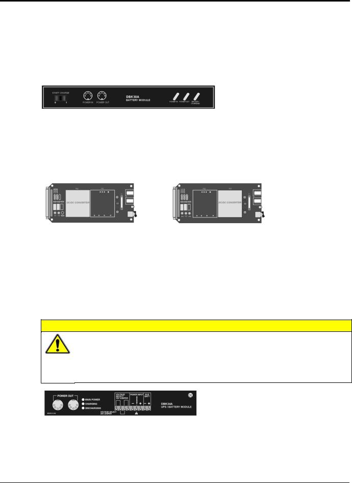
Power supply type DBKs are typically used in laboratory, automotive, and field applications. Input power can come from any +10 to +20 VDC source, or from an AC source by using an appropriately rated AC-to- DC adapter. The DBK30A rechargeable power supply can power DBK modules where AC mains are not available (the DBK30A outputs 28 V for powering transducers). For a large number of DBK cards, the DBK32A or DBK33 can be installed into an expansion slot. The DBK33 is used when +5 V is required in addition to ±15 VDC. The DBK34 provides a steady 12 or 24 VDC while working with vehicle electrical systems that may be turned on or off during testing.
Power Supply
Product |
Name/Description |
Power |
DBK30A |
Rechargeable Battery/Excitation Module |
+12-14, 24-28 VDC (3.4 A-hr @ 14 VDC) |
DBK32A |
Auxiliary Power Supply Card |
±15 V @ 500 mA |
DBK33 |
Triple-Output Power Supply Card |
±15 V @ 250 mA; +5 V @ 1 A |
DBK34 |
Vehicle UPS Module |
12/24 VDC (5 A-hr @12 VDC) |
DBK34A |
UPS Battery Module |
12/24 VDC (5 A-hr @12 VDC) |
Tips on Setting up a Data Acquisition System
A successful installation involves setting up equipment and setting software parameters. In addition to this manual, you may need to consult your Daq device or LogBook user’s manual.
DBKs should be configured before connections are made and power is applied. This sequence can prevent equipment damage and will help ensure proper operation on startup. Many DBKs have on-board jumpers and/or DIP switches that are used for setting channels and other variables. You will need to refer to the individual DBK document modules to ensure that the DBKs are properly configured for you application.
Prior to designing or setting up a custom data acquisition system, you should review the following tips. After reviewing the material you can write out the steps to setup a system that will best meet your specific application needs.
1.The end use of the acquisition data should be used to determine how you set up and program your acquisition system. Prior to creating the system you should understand its layout and know how you are going to assign the channels. If you can answer the following questions you are off to a good start. If not, you need to find the answers.
•What engineering units, ranges, sampling rates, etc. are best for your data?
•Will the data be charted graphically, statistically processed, or exported to other programs?
•How will the data be used?
•How will the data be saved?
•What are the system power requirements? Using several DBKs or transducers that require excitation current may require an extra power supply, e.g., a DBK32A.
2.Assign channel numbers.
3.Plan the location of transducers, cable runs, DBKs, the acquisition device [LogBook or Daq device], and the computer. Label your transducers, cables, and connectors to prevent later confusion.
pg. 12, DBK Basics |
967794 |
Daq Systems |

4.When configuring your LogBook or Daq device(s) consider the following:
•LogBook calibration is typically performed automatically through LogView software; however, some DBKs may require manual calibration.
•The DaqBook/100 Series and DaqBook/200 Series devices, and DaqBoards (ISA type) have internal jumpers and switches that you must set manually to match your application.
•Some DaqBook/100 Series and DaqBook/200 Series models are partially configured in software.
•DaqBook/2000 Series devices have no jumpers or internal switches and are configured entirely through software.
•Daq PC-Cards are configured entirely in software.
•DaqBoard/2000 Series boards are PCI type boards. They have no jumpers or switches and are configured entirely through software.
•cPCI DaqBoard/2000c Series boards are compact PCI (cPCI) type boards. They have no jumpers or switches and are configured entirely through software.
•You may need to refer to other documentation, such as Quick Starts, Installation Guides, User’s Manuals, and pertinent DBK document modules.
5.Perform all hardware configurations before connecting signal and power. Remember to configure all the DBK cards and modules for your application. Several jumpers and DIP switches may need to be set (channel, gain, filters, signal mode, etc).
6.Setting up channel parameters often requires both hardware and software setup.
7.Route and connect all signal and power cables while all power is turned OFF.
8.To minimize electrical noise, route all signal lines away from any RF or high-voltage devices.
9.Follow your device’s specific installation instructions. For certain devices software should be installed first; for others, hardware should be installed prior to software installation.
10.After software is loaded, remember to set the software parameters as needed for your application. The software must recognize all the hardware in the system. Measurement units and ranges should be checked to verify that they meet your application requirements.
11.Remember to set all channels to the proper mode for your DBK or other signal source.
12.After your system is up and running, verify proper data acquisition and data storage.
13.Verify system accuracy; adjust ranges or calibrate as needed.
14.Device specific information regarding system setup and expansion can be found in the Daq and LogBook User’s manuals; and in the applicable DBK document modules of this manual.
15.If you are considering system expansion, review the DBK10, DBK41, and DBK60 document modules. The best option depends on the number of DBK cards in your system. For just a few cards, use the stackable 3-slot DBK10 low-profile expansion enclosure. For more than six cards, use the 10-slot DBK41. DBK41s can be daisy-chained to one-another to handle a large number of DBKs.
16.In regard to power management, you should review the DBK30A, DBK32A, and DBK33 document modules. For portable applications, the compact DBK30A rechargeable power supply can provide power to the DBK10 or DBK41. The DBK30A also includes a 28 V output for powering 4 to 20 mA transducers. For applications with many DBK cards (initially or in future expansion), the DBK32A or DBK33 can be installed into any expansion slot. The DBK32A provides ±15 VDC and the DBK33 provides ±15 VDC and +5 VDC.
Daq Systems |
967794 |
DBK Basics, pg. 13 |
Power Supplies and Power Connectors
Power supplies convert the raw power they receive into a lower DC voltage and/or current for use by devices with various power demands. Many of the power supplies that are used to power data acquisition equipment are of the switching-mode type. These devices provide a regulated output whether the power supply’s input is, for example, 60 Hz, 120 VAC as in the United States or, 50 Hz, 220 VAC as found in European countries. Small power supplies, that do not switch, consist of simple transformer/rectifiers and filtered capacitors; and operate over a smaller voltage range.
Some manufacturers improve the power output of their units over time, without changing the model number. For example, one very popular power supply was previously rated at 15 VDC @ 2.7 amps, yet more recent versions of the same model number are rated 15 VDC @ 3.3 amps. Read the manufacturer’s information pertaining to your power supplies so you don’t accidentally overload the supply.
DBKs – The following table indicates the type of power supply that is typically used with certain DBKs.
|
These DBKs can be powered from a |
|
|
These DBKs can be powered from a |
|
||
|
Switching-Mode Type Power Supply |
|
|
Transformer/Rectifier Type, Unregulated Power Supply |
|
||
|
The switching-mode power supply typically |
|
|
The DBKs in this column use up to15 VDC @ |
|
||
|
receives power from a 100 to 240 VAC source at 50 |
|
|
900 mA. This transformer/rectifier type power |
|
||
|
Hz to |
|
|
|
supply receives power from a 110 to 125 VAC |
|
|
|
60 Hz and converts it to the 15 VDC required by the |
|
|
source, at 60 Hz, and converts it to the 15 VDC |
|
||
|
DBK. |
|
|
|
required. |
|
|
|
DBK |
Description |
|
|
DBK |
Description |
|
|
DBK32A |
Auxiliary Power Supply Card |
|
|
DBK23 |
Optically Isolated Digital-Input Module |
|
|
DBK33 |
Triple-Output Power Supply Card |
|
|
DBK24 |
Optically Isolated Digital-Output Module |
|
|
DBK42 |
5B Isolated Signal Conditioning Module |
|
|
DBK43A |
Strain Gage Measurement Module |
|
|
|
|
|
|
|
|
|
|
DBK70 |
Vehicle Network Interface |
|
|
DBK50 |
Isolated High-Voltage Input Module |
|
|
|
|
|
|
DBK51 |
Isolated Low-Voltage Input Module |
|
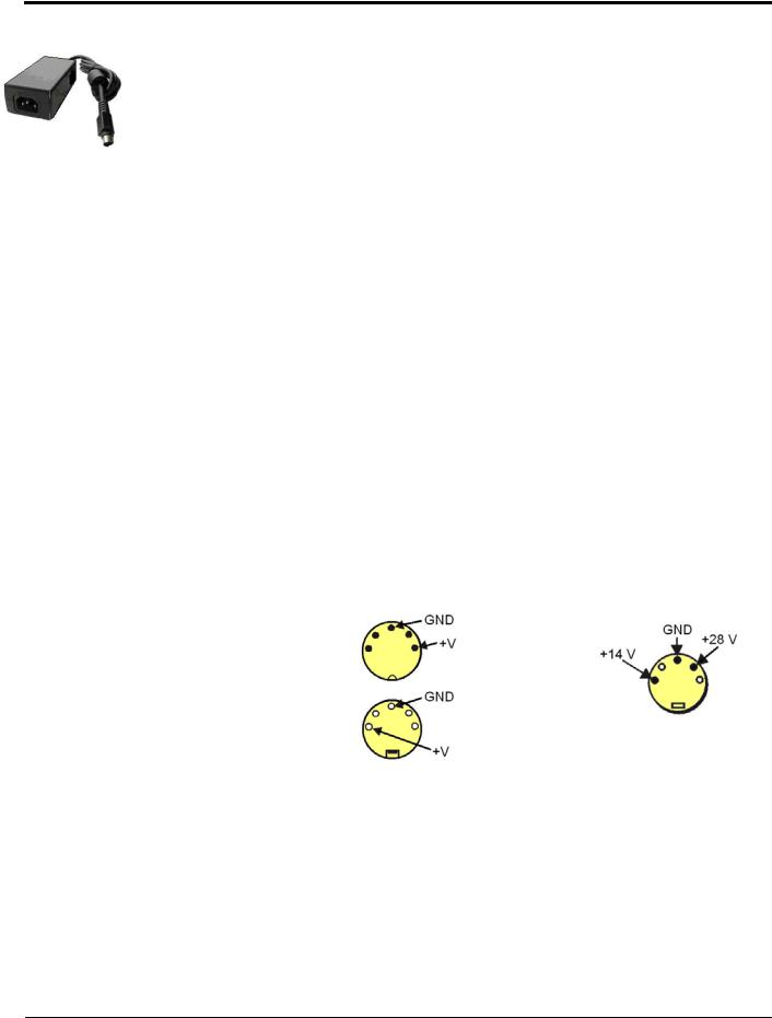
The DIN5 is the system’s basic power connector (see the following figure). The CA-115 is a 6-in. cable with a plug (male) DIN5 connector on both ends. The CA-115 is used to connect DBK32As [or DBK33s] in parallel when they are to be powered by the same power supply.
Power Output Connector |
|
|
Male connector located on the |
|
|
power supply cable and on both |
|
|
ends of the CA-115 cable. |
|
|
Power Input Connector |
|
|
Female connector located on |
|
|
the device being powered |
(see Notes 1 and 2) |
|
(DaqBook, DBK32A, DBK33). |
||
|
||
DIN5 Power Connectors |
DIN5 Power Out |
|
On a DBK34 and DBK34A |
||
|
Note 1: DIN5 connectors for LogBook, DBK34, and DBK34A have threaded retaining rings.
Note 2: In regard to the above pinout for the DBK34 and DBK34A Power Out DIN5 connector, the 28 V pin is only active when the device is in the 28 VDC mode; however, the 14 V pin is active regardless of the mode selected.
pg. 14, DBK Basics |
967794 |
Daq Systems |
An Introduction to Power-Related DBKs
The power-related DBK options are the DBK30A, DBK32A, DBK33, DBK34, and DBK34A. From the standpoint of providing reliable power, these DBKs have proven convenient in laboratory, automotive, and field applications.
Input power for these devices can come from any 10 to 20 VDC source, or from an AC source via an appropriate AC-to-DC adapter.
A brief synopsis of the DBK power options follows. Refer to the respective document modules for complete information.
DBK30A module - provides power at 14 and 28 VDC with a rated capacity of 3.4 A-hr @ 14 VDC.
The DBK30A’s 28 V output will power 4 to 20 mA transducers. The module’s rechargeable power supply can power DBK modules in situations where AC mains are not available.
Note: Some transducers (e.g., 2-wire 4-20 mA transmitters, bridge-configured sensors, etc) require an excitation voltage in order to work properly. The DBK30A supplies 14 and 28 VDC. Consult transducer documentation before applying power.
DBK32A - provides ±15 VDC @ 500 mA. DBK33 - provides ±15 VDC @ 250 mA and +5 VDC @ 1000 mA.
The DBK32A and DBK33 power cards attach directly to the P1 analog expansion bus where they supply power to DBK analog expansion cards. The DBK32A and the DBK33 can be powered from an included AC adapter, an optional DBK30A battery module, or from a +10 to +20 VDC source such as a car battery.
When installed in a DBK10 three-slot expansion chassis, the DBK32A or DBK33 supplies power to the analog DBK [that is to receive power] via a CA-37-x cable.
If used with the DBK41 ten-slot expansion enclosure, the DBK32A or DBK33 installs into one of the analog expansion slots on the DBK41’s backplane. A power card in any DBK41slot (other than the leftmost, when viewed from the rear) will power the other cards that are connected to the DBK41’s backplane.
CAUTION
If using a DBK32A or a DBK33 with a DaqBook/100 Series, DaqBook/200 Series, or a DaqBoard [ISA type] device, you must entirely remove the shunt jumpers from JP1. Failure to do so will result in damage to the 8254 timer chip. Refer to the power card document modules and to the Daq device Hardware sections of the DaqBook/100 Series and DaqBook/200 Series, and DaqBoard [ISA] user’s manuals for JP1 locations and configurations.
DBK34A module – provides 12 or 24 VDC with a 5.0 or 2.5 A-hr capacity (respectively).
The DBK34A is classified as a UPS / Battery module. The module can be used for in-vehicle testing in scenarios where the vehicle’s electrical system does not affect acquisition device power during starter-current surge, or power-off.
Daq Systems |
967794 |
DBK Basics, pg. 15 |

Power Requirements
The improper use of power can cause system damage. The following terms are important in regard to understanding your system’s power needs.
•Supply power for signal conditioning type DBKs comes from a primary acquisition device, such as a DaqBook/2000 Series device or LogBook, or from a power card or module. If needed, the DBK32A or DBK33 can provide additional power to meet DBK power demands. The DBK power supplies work off of low-voltage DC that can come from an AC adapter or from a DC source, such as a car battery.
•Demand for power comes from DBK cards and modules [and in some systems, from transducers]. You should use the DBK Power Requirement Worktable to calculate your system’s power needs. After completing the table, compare the total power demand to the supply power.
•Distribution of power to most DBKs is via the P1 interface. The DBK41 expansion chassis has a jumper to isolate +5 VDC power from P1. The P1 Pin designations are as follows:
Pin 1: +5 VDC
Pin 2: -15 VDC
Pin 21: +15 VDC Pin 7: digital ground
Pin 28: analog ground Pin 29: analog ground
Note: Certain DBK modules have their own internal power supplies and require only 10 VDC to 20 VDC.
LogBook
The LogBook [with no DBKs attached] uses approximately 12 Watts of power. If using battery-power, you can compute operational endurance from your battery’s watt×hr rating and the following calculation tables.
DaqBoard/2000 Series Boards
DaqBoard/2000 Series and cPCI DaqBoard/2000c Series Boards use 3.5 watts of power
(700 mA @ 5 VDC) from their host computer. Power consumption can be up to 10 W with external accessories.
Avoid power cycling the host PC. Wait 10 seconds after powering down the host PC before powering it back on. This will allow any residual voltages to decay enabling the DaqBoard/2000 Series or /2000c Series board to start up in a known good state.
DaqBook/100 Series & /200 Series, DaqBoard [ISA], and Daq PC-Card
If using power from AC mains (through adapter), you need not worry about Daq device power use. If using battery-power, you can compute operational endurance from the battery’s watt×hr rating and power tables. Daq PC-Card and DaqBoard use power from their host PC.
DaqBook/100 and DaqBook/200 Series devices use no power from the PC, but do require DC voltage from an AC-to-DC adapter, or another suitable source. Voltage needs are as follows:
•+7 to +20 VDC for DaqBook/100, DaqBook/112, and DaqBook/120
•+10 to +24 VDC for DaqBook/216
•9 to +18 VDC for DaqBook/200 and DaqBook/260.
Various AC adapter models support power grids of USA, Europe, Japan, and Asia.
pg. 16, DBK Basics |
967794 |
Daq Systems |
DaqBook/2000 Series Devices
If using power from AC mains (through adapter), you need not worry about Daq device power use. If using battery-power, you can compute operational endurance from the battery’s watt×hr rating and power tables.
DaqBook/2000 Series devices use no power from the PC, but do require DC voltage from an AC-to-DC adapter with a supply range of +10 VDC to +30 VDC, or another suitable DC source.
Various AC adapter models support power grids of USA, Europe, Japan, and Asia.
Power Requirements Table
|
|
|
Device |
Power Required (Watts) |
|
|||
|
|
|
DaqBook/100 |
|
510 mA @ |
12 VDC = |
6.12 W |
|
|
|
|
DaqBook/112 |
|
360 mA @ |
12 VDC = |
4.32 W |
|
|
|
|
|
|
||||
|
|
|
|
|
|
|
|
|
|
|
|
DaqBook/120 |
|
510 mA @ |
12 VDC = |
6.12 W |
|
|
|
|
DaqBook/200 |
|
620 mA @ |
12 VDC = |
7.44 W |
|
|
|
|
|
|
||||
|
|
|
DaqBook/216 |
|
600 mA @ |
12 VDC = |
7.2 W |
|
|
|
|
DaqBook/260 |
|
620 mA @ |
12 VDC = |
7.44 W |
|
|
|
DaqBook/2001, /2005 |
1000 mA @ |
15 VDC = |
15.0 W |
|
||
|
|
|
DaqBook/2020 |
|
1000 mA @ |
15 VDC = |
15.0 W |
|
|
|
DaqOEM/2001, /2005 |
1000 mA @ |
15 VDC = |
15.0 W |
|
||
|
|
DaqLab |
1000 mA @ |
15 VDC = |
15.0 W |
|
||
|
|
DaqScan |
1000 mA @ |
15 VDC = |
15.0 W |
|
||
|
|
DaqBoard/100A |
1330 mA @ |
5 VDC = |
6.65 W |
|
||
|
|
|
DaqBoard/112A |
|
970 mA @ |
5 VDC = |
4.85 W |
|
|
|
|
DaqBoard/200A |
|
1700 mA @ |
5 VDC = |
8.5 W |
|
|
|
|
DaqBoard/216A |
|
1340 mA @ |
5 VDC = |
6.7 W |
|
|
|
|
DaqBoard/2000 Series board |
|
700 mA @ |
5 VDC = |
3.5 W |
|
|
|
|
|
|
(Note 1) |
|
|
|
|
|
|
cPCI DaqBoard/2000c Series board |
|
700 mA @ |
5 VDC = |
3.5 W |
|
|
|
|
|
|
(Note 1) |
|
|
|
|
|
|
DaqBook/2000A |
|
Under No External Load (0W): |
|
||
|
|
|
DaqBook/2000X |
|
467mA @ 15VDC = 7 W |
|
||
|
|
|
|
|
Under Full External Load (15W): |
|
||
|
|
|
|
|
1533mA @ 15VDC = 23 W |
|
||
|
|
|
DaqBook/2000E |
|
Under No External Load (0W): |
|
||
|
|
|
|
|
1133mA @ 15VDC = 17 W |
|
||
|
|
|
|
|
Under Full External Load (15W): |
|
||
|
|
|
|
|
2200mA @ 15VDC = 33 W |
|
||
|
|
|
Daq PC-Card/112B |
|
Normal Operation: |
|
|
|
|
|
|
Daq PC-Card/216B |
|
160 mA @ 5 VDC = 0.8W |
|
||
|
|
|
|
|
Power Down Mode: |
|
|
|
|
|
|
|
|
40 mA @ 5 VDC = 0.2 W |
|
||
|
|
Note 1: For DaqBoard/2000 Series and |
/2000c Series boards, consumption can be |
|
||||
|
|
|
up to 10 W with external accessories. |
|
|
|
||
|
|
|
|
|
|
|
|
|
Daq Systems |
967794 |
|
|
|
DBK Basics, pg. 17 |
|||

Calculating Your System’s Power Needs
Use the chart below and the worktable on the next page to ensure your system will have sufficient power. If the load (calculated in the worktable) exceeds available power (from the chart at the right), you must add a power card or a module such as a DBK32A or DBK33.
Available Power Chart — Supply to Expansion Devices
|
Product |
Available Power |
|
|
|
LogBook |
|
+5 VDC @ 0.10 A from P1-1, P2-18, P2-20, P3-20 |
|
|
|
|
+15 VDC @ 0.15 A from P1-21 |
|
|
|
|
+15 VDC @ 0.05 A from P3-19 |
|
|
|
|
-15 VDC @ 0.15 A from P1-2 |
|
|
|
|
-15 VDC @ 0.05 A from P3-37 |
|
|
DaqBook/100 |
2100 mW |
|
|
|
DaqBook/112 |
|
2400 mW |
|
|
DaqBook/120 |
|
2100 mW |
|
|
DaqBook/200 |
|
4000 mW |
|
|
|
|
||
|
DaqBook/216 |
|
4000 mW |
|
|
DaqBook/260 |
|
4000 mW |
|
|
DaqBook/2000 AEX |
15000 mW; 5V at 1 A; ± 15 V at 500 mA each |
|
|
|
DaqBook/2001, /2005 |
10,000 mW |
|
|
|
DaqBook/2020 |
|
7,000 mW |
|
|
DaqOEM/2001, /2005 |
|
10,000 mW |
|
|
DaqLab |
|
10,000 mW |
|
|
DaqScan |
10,000 mW |
|
|
|
DaqBoard/100A |
3300 mW |
|
|
|
DaqBoard/112A |
|
3300 mW |
|
|
DaqBoard/200A |
|
3000 mW |
|
|
DaqBoard/216A |
|
3000 mW |
|
|
DaqBoard/260A |
|
3000 mW |
|
|
DaqBoard/2000 Series |
5000 mW; 5 V at 1 A; ±15 V at 75 mA each (with |
|
|
|
& /2000c Series |
exception of DaqBoard/2002 and /2002c) |
|
|
|
Daq PC-Card/112B |
0 mW |
|
|
|
Daq PC-Card/216B |
|
0 mW |
|
|
|
|
|
|
pg. 18, DBK Basics |
967794 |
Daq Systems |

Available Power Chart — Supply to Expansion Devices
|
|
Product |
Available Power |
|
|
|
|
DBK32 |
|
7500 mW |
|
|
|
DBK32A |
|
15000 mW |
|
|
|
|
|||
|
DBK33 |
7500 mW |
|||
|
|||||
|
|
DBK34 |
|
5 A-hr in 12 V mode; fused at 8 A |
|
|
|
DBK34A |
|
5 A-hr in 12 V mode; fused at 8 A |
|
|
|
|
|
|
|
Use the following procedure and table to calculate the required system power.
1.In the Quantity column (5th), list the number of DBKs of that type in your system.
2.In the Sub Total column (7th), enter the product of column 5 and column 6 (mW).
3.Add the Sub Total column, and enter the sum at the bottom right of the table. This result is your power requirement in mW.
DBK32, DBK32A, and DBK34 cannot supply +5 VDC. In cases that require +5 VDC, if the +5 VDC requirement exceeds 500 mW from a LogBook or Daq device, then a DBK33 must be used. Note that DBK33 can supply 1000 mW at +5 VDC.
Note: The DBK34 has an 8 amp fuse, and has a capacity of 5 A-hr when in the 12V mode, and a capacity of 2.5 A-hr when in the 24V mode.
Daq Systems |
967794 |
DBK Basics, pg. 19 |

DBK Power Requirement Worktable—Demand
|
|
DBK |
|
|
|
|
Voltage Reference |
|
|
|
Calculation |
|
||||||
|
|
|
|
|
|
|
|
|
|
|||||||||
|
|
Options |
|
|
+15 VDC |
|
|
-15 VDC |
|
|
+5 VDC |
|
Quantity |
|
× mW |
|
= Sub Total |
|
|
|
|
|
|
|
|
|
|
|
|
|
|
|
|||||
|
|
DBK1 |
|
|
0 |
|
|
0 |
|
|
0 |
|
|
|
0 |
|
|
|
|
|
DBK2 |
|
|
18 mA |
|
|
18 mA |
|
|
5 mA |
|
|
|
565 |
|
|
|
|
|
DBK4 |
|
|
95 mA |
|
|
80 mA |
|
|
25 mA |
|
|
|
2750 |
|
|
|
|
|
DBK5 |
|
|
2 mA |
|
|
2 mA |
|
|
15 mA |
|
|
|
135 |
|
|
|
|
|
DBK7 |
|
|
14 mA |
|
|
8 mA |
|
|
18 mA |
|
|
|
420 |
|
|
|
|
|
DBK8 |
|
|
15 mA |
|
|
15 mA |
|
|
<1 mA |
|
|
|
455 |
|
|
|
|
|
DBK9 |
|
|
21 mA |
|
|
16 mA |
|
|
<1 mA |
|
|
|
560 |
|
|
|
|
|
DBK10 |
|
|
0 |
|
|
0 |
|
|
0 |
|
|
|
0 |
|
|
|
|
|
DBK11A |
|
|
0 |
|
|
0 |
|
|
0 |
|
|
|
0 |
|
|
|
|
|
DBK12 |
|
|
15 mA |
|
|
15 mA |
|
|
<1 mA |
|
|
|
455 |
|
|
|
|
|
DBK13 |
|
|
15 mA |
|
|
15 mA |
|
|
<1 mA |
|
|
|
455 |
|
|
|
|
|
DBK15 |
|
|
16 mA |
|
|
16 mA |
|
|
<1 mA |
|
|
|
485 |
|
|
|
|
|
DBK16 |
|
|
37 mA |
|
|
32 mA |
|
|
<1 mA |
|
|
|
1040 |
|
|
|
|
|
|
|
|
|
|
|
|
|
|
|
|
|
|||||
|
|
DBK17 |
|
|
30 mA |
|
|
30 mA |
|
|
<1 mA |
|
|
|
905 |
|
|
|
|
|
DBK18 |
|
36 mA |
|
36 mA |
|
<1 mA |
|
1085 |
|
|
|
|||||
|
|
DBK19 |
|
|
6 mA |
|
|
7 mA |
|
|
<1 mA |
|
|
|
200 |
|
|
|
|
|
DBK20 |
|
|
|
|
|
|
|
|
|
|
|
|
|
|
|
|
|
|
|
|
0 |
|
|
0 |
|
|
<10 mA |
|
|
|
50 |
|
|
|
|
|
|
DBK21 |
|
|
0 |
|
|
0 |
|
|
<10 mA |
|
|
|
50 |
|
|
|
|
|
|
|
|
|
|
|
|
|
|
|
|
|
|||||
|
|
DBK23*** |
|
|
0 |
|
|
0 |
|
|
<2 mA |
|
|
|
10 |
|
|
|
|
|
DBK24*** |
|
|
0 |
|
|
0 |
|
|
<2 mA |
|
|
|
10 |
|
|
|
|
|
DBK25 |
|
|
0 |
|
|
0 |
|
|
<2 mA |
|
|
|
10 |
|
|
|
|
|
DBK40 |
|
|
0 |
|
|
0 |
|
|
0 |
|
|
|
0 |
|
|
|
|
|
DBK41 |
|
|
0 |
|
|
0 |
|
|
0 |
|
|
|
0 |
|
|
|
|
|
DBK42 |
|
|
<1 mA |
|
|
<1 mA |
|
|
<1 mA |
|
|
|
35 |
|
|
|
|
|
DBK43A*** |
|
|
<1 mA |
|
|
<1 mA |
|
|
<1 mA |
|
|
|
35 |
|
|
|
|
|
DBK44 |
|
|
<1 mA |
|
|
<1 mA |
|
|
60 mA (Note 1) |
|
|
|
330 |
|
|
|
|
|
DBK45 |
|
|
52 mA |
|
|
52 mA |
|
|
<1 mA |
|
|
|
1565 |
|
|
|
|
|
DBK46 |
|
|
20 mA |
|
|
20 mA |
|
|
400 mA |
|
|
|
2600 |
|
|
|
|
|
DBK48 |
|
|
<1 mA |
|
|
<1 mA |
|
|
<1 mA |
|
|
|
35 |
|
|
|
|
|
|
|
|
|
|
|
|
|
|
|
|
|
|||||
|
|
DBK50*** |
|
|
<1 mA |
|
|
<1 mA |
|
|
<1 mA |
|
|
|
35 |
|
|
|
|
|
DBK51*** |
|
|
<1 mA |
|
|
<1 mA |
|
|
<1 mA |
|
|
|
35 |
|
|
|
|
|
DBK52 |
|
|
6 mA |
|
|
7 mA |
|
|
<1 mA |
|
|
|
200 |
|
|
|
|
|
DBK53 |
|
|
15 mA |
|
|
15 mA |
|
|
<1 mA |
|
|
|
455 |
|
|
|
|
|
DBK54 |
|
|
15 mA |
|
|
15 mA |
|
|
<1 mA |
|
|
|
455 |
|
|
|
|
|
DBK55 |
|
|
30 mA |
|
|
20 mA |
|
|
40 mA |
|
|
|
950 |
|
|
|
|
|
DBK60 |
|
|
0 |
|
|
0 |
|
|
0 |
|
|
|
0 |
|
|
|
|
|
|
|
|
|
|
|
|
|
|
Total Power Requirement in mW |
|
|
|
||||
Note 1: DBK44’s 60 mA value is based on 30 mA for each of two 5B modules. This value will be higher if using 5B module 5B38 (200 mA for each 5B38), or if using 5B39 (170 mA for each 5B39). Refer to the DBK44 document module for more information.
Note 2: DBK2 and DBK5 are not used with LogBook.
***Three asterisks indicate that the DBK is a module with internal power supply; powered separately.
This table is continued.
pg. 20, DBK Basics |
967794 |
Daq Systems |
Loading...