

Olympus CX31-P Instructions Manual

INSTRUCTIONS
CX31-P
POLARIZING MICROSCOPE
This instruction manual is for the Olympus Polarizing Microscopes Model CX31-P. To ensure the
safety, obtain optimum performance and to familiarize yourself fully with the use of this microscope,
we recommend that you study this manual thoroughly before operating the microscope. Retain this
instruction manual in an easily accessible place near the work desk for future reference.
A X 7 3 4 9
This publication is printed on 100% recycled paper


4-1 Microscope Frame .................................................................................................................................................................................8
CONTENTS
CX31-P
IMPORTANT — Be sure to read this first for safe use of the equipment. —
1-3
.................................................................. 15
1 MODULE NOMENCLATURE
2 CONTROLS
3
SUMMARY OF POLARIZED LIGHT OBSERVATION PROCEDURE
4 OPERATION
5
6-7
8-14
4
Correct assembly and adjustments are critical for the microscope to manifest its full performance. If you are going to
assemble the microscope by yourself, please read Chapter 9, “ASSEMBLY” (Pages 23 to 26). For the assemblies of the
modules for which instruction manuals are available, refer to their instruction manuals.
1 Turning the Lamp ON
3 Using the Filters
2 Field Iris Diaphragm
4-2 Focusing Module ...................................................................................................................................................................................... 9
4-3 Observation Tube ...........................................................................................................................................................................9-10
2 Adjusting the Diopter
4 Using the Eyepiece Micrometer Disk
1 Placing Specimen on the Stage
4-4 Intermediate Tube for Polarizing Observation (U-PA).......................................................................11
4-5 Rotary Stage ................................................................................................................................................................................................ 12
2 Rotating the Stage
4-6 Condenser...................................................................................................................................................................................................... 13
1 Centering the Field Iris Diaphragm 2 Using the Aperture Iris Diaphragm
4-7 Immersion Objective ....................................................................................................................................................................... 14
1 Adjusting the Coarse Adjustment Knob Rotation Tension
2 Using the Simplified Pre-focusing Knob
1 Adjusting the Interpupillary Distance
3 Using the Eye Shades
1 Using the Bertrand’s Lens 2 Using the Analyzer

2 Centering the Rotary Stage 1 Cross-Nicol Adjustment
3 Adjusting the Centering Adapter
for Objective
PROPER SELECTION OF THE POWER SUPPLY CORD ..................................................................
27-28
19
20
23-26
21-22
5 POLARIZED LIGHT OBSERVATION
5-1 Preparation ...........................................................................................................................................................................................15-17
5-2 Orthoscopic Observation ......................................................................................................................................................... 18
5-3 Conoscopic Observation .......................................................................................................................................................... 18
15-18
6 SPECIFICATIONS
7 OPTICAL CHARACTERISTICS
8 TROUBLESHOOTING GUIDE
9 ASSEMBLY
1
CX31-P
IMPORTANT
SAFETY PRECAUTIONS
1. After the equipment has been used in an observation of a specimen that
is accompanied with a potential of infection, clean the parts coming in
contact with the specimen to prevent infection.
· When moving the microscope, be sure to remove the specimen to
prevent it from dropping and scattering, and hold the microscope
by the positions shown in Fig. 2 on the next page.
· In case the specimen is damaged by mistake, promptly take the action
for preventing infection.
· The microscope becomes unstable when its height is increased by
attached modules. In this case, be sure to take countermeasures for
preventing it from toppling down and dropping the specimen.
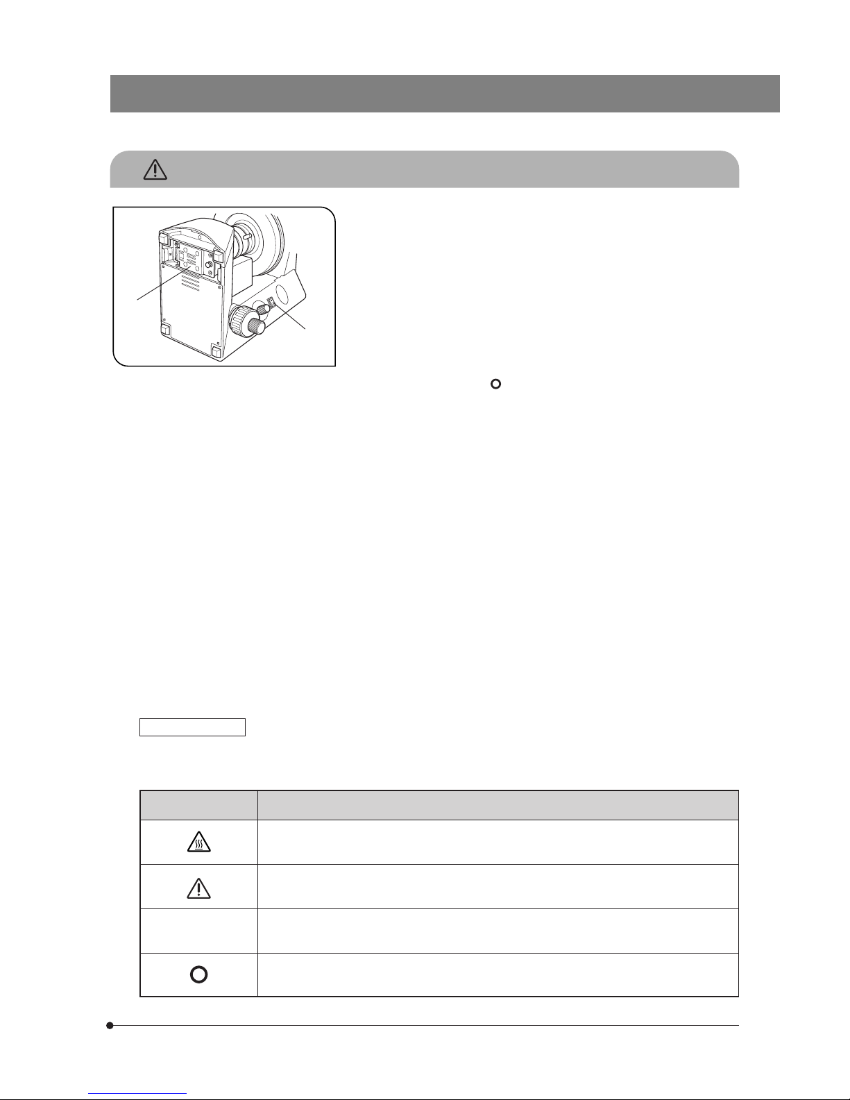
2. To avoid potential shock hazards and burns when replacing the lamp bulb, set
the main switch 1 to “ ” (OFF) then disconnect the power cord from the wall
outlet in advance and, whenever you replace the bulb during use or right after
use, allow the lamp replacement cover 2 and bulb to cool before touching.
3. Install the microscope on a sturdy, level table or bench so as not to block
the air vents on the underside of the base. Do not place the microscope
on a soft surface into which the microscope may sink, as this could result
in blocking the air vents and cause overheating or a fire.
4. Always use the power cord provided by Olympus. If no power cord is
provided, please select the proper power cord by referring to the section
“PROPER SELECTION OF THE POWER SUPPLY CORD” at the end of
this instruction manual. If the proper power cord is not used, product
safety performance cannot be warranted.
5. When installing the microscope, route the power cord away from the
microscope frame. Should the power cord come in contact with a hot
part, the power cord could melt and cause electric shock.
6. Always ensure that the grounding terminal of the microscope and that of the
wall outlet are properly connected. If the equipment is not grounded, Olympus
can no longer warrant the electrical safety performance of the equipment.
7. Never set the main switch 1 to “ I ” (ON) while a metallic object is present
in the air vents of the microscope, as this could result in electrical shock,
personal injury and equipment damage.
8. After operation or in case of abnormality, be sure to disconnect the power
cord from the connector on the microscope or from the wall power outlet
Symbol Explanation
l
IIndicates that the surface becomes hot, and should not be touched with bare hands.
Fig. 1
Safety Symbols
The following symbols are found on the microscope. Study the meaning of the symbols and always use the equipment in
the safest possible manner.
Before use, carefully read the instruction manual. Improper use could result in personal injury to
the user and/or damage to the equipment.
Indicates that the main switch is ON.
Indicates that the main switch is OFF.
1
2
2
If the warning label is stained or peeled off, contact Olympus.
1
Getting Ready
2
Maintenance and Storage
Warning Label
A warning indication label is attached to every part where special precaution is required when handling and using the
microscope. Always heed the warnings.
Warning label position
Bottom of microscope frame
Warning against high temperature in lamp bulb replacement
1. A microscope is a precision instrument. Handle it with care and avoid
subjecting it to sudden or severe impact.
2. Do not use the microscope where it is subjected to direct sunlight, high
temperature and humidity, dust or vibrations. (For the operating conditions, see chapter 6, “SPECIFICATIONS” on page 19.)
3. Always use the tension adjustment ring to adjust the rotation tension of
the coarse adjustment knob.
4. The microscope is ventilated by natural convection. Be sure to leave
enough spaces (10 cm or more) around it when installing it.
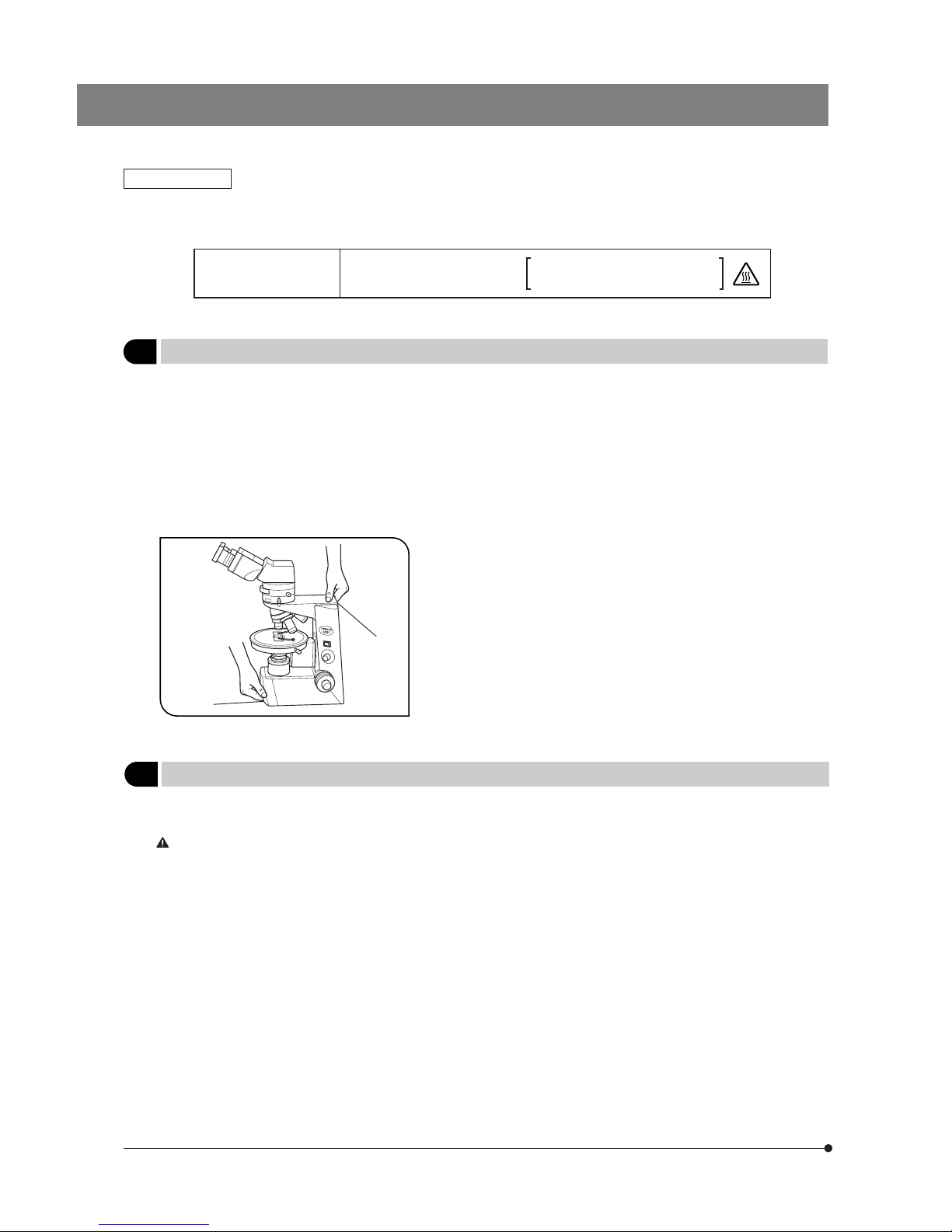
5. When carrying the microscope, hold it by the bottom of the base 1 and
finger hook on the rear 2 as shown on the left and carry carefully.
# To prevent damage, do not hold the microscope by the stage or
observation tube. Before carrying, remove the specimen and filters
to prevent them from dropping.
# If the microscope is displaced by sliding on the desktop, the rubber
feet may be damaged or separated from the bottom.
Fig. 2
1. Clean all glass components by wiping gently with gauze. To remove fingerprints or oil smudges, wipe with gauze slightly
moistened with a mixture of ether (70%) and alcohol (30%).
Since solvents such as ether and alcohol are highly flammable, they must be handled carefully. Be sure to keep
these chemicals away from open flames or potential sources of electrical sparks –– for example, electrical
equipment that is being switched on or off. Also remember to always use these chemicals only in a wellventilated room.
2. Do not attempt to use organic solvents to clean the microscope components other than the glass components. To clean
them, use a lint-free, soft cloth slightly moistened with a diluted neutral detergent.
3. Do not disassemble any part of the microscope as this could result in malfunction or reduced performance.
4. When not using the microscope, ensure that the frame is cooled down and store it in a dry locker or cover it with
a dust cover.
1
2

3
CX31-P
The following symbols are used to set off text in this instruction manual.
: Indicates that failure to follow the instructions in the warning could result in bodily harm to the
user and/or damage to equipment (including objects in the vicinity of the equipment).
# : Indicates that failure to follow the instructions could result in damage to equipment.
}: Indicates commentary (for ease of operation and maintenance).
3
Caution
If the microscope is used in a manner not specified by this manual, the safety of the user may be imperiled. In addition, the
equipment may also be damaged. Always use the equipment as outlined in this instruction manual.
NOTE: This equipment has been tested and found to comply with the limits for a Class A digital device,
pursuant to Part 15 of the FCC Rules. These limits are designed to provide reasonable protection
against harmful interference when the equipment is operated in a commercial environment. This
equipment generates, uses, and can radiate radio frequency energy and, if not installed and used in
accordance with the instruction manual, may cause harmful interference to radio communications.
Operation of this equipment in a residential area is likely to cause harmful interference in which case
the user will be required to correct the interference at his own expense.
FCC WARNING: Changes or modifications not expressly approved by the party responsible for compliance
could void the user’s authority to operate the equipment.
This device complies with the requirements of directive 98/79/EC concerning in vitro diagnostic medical
devices. CE marking means the conformity to the directive.
4
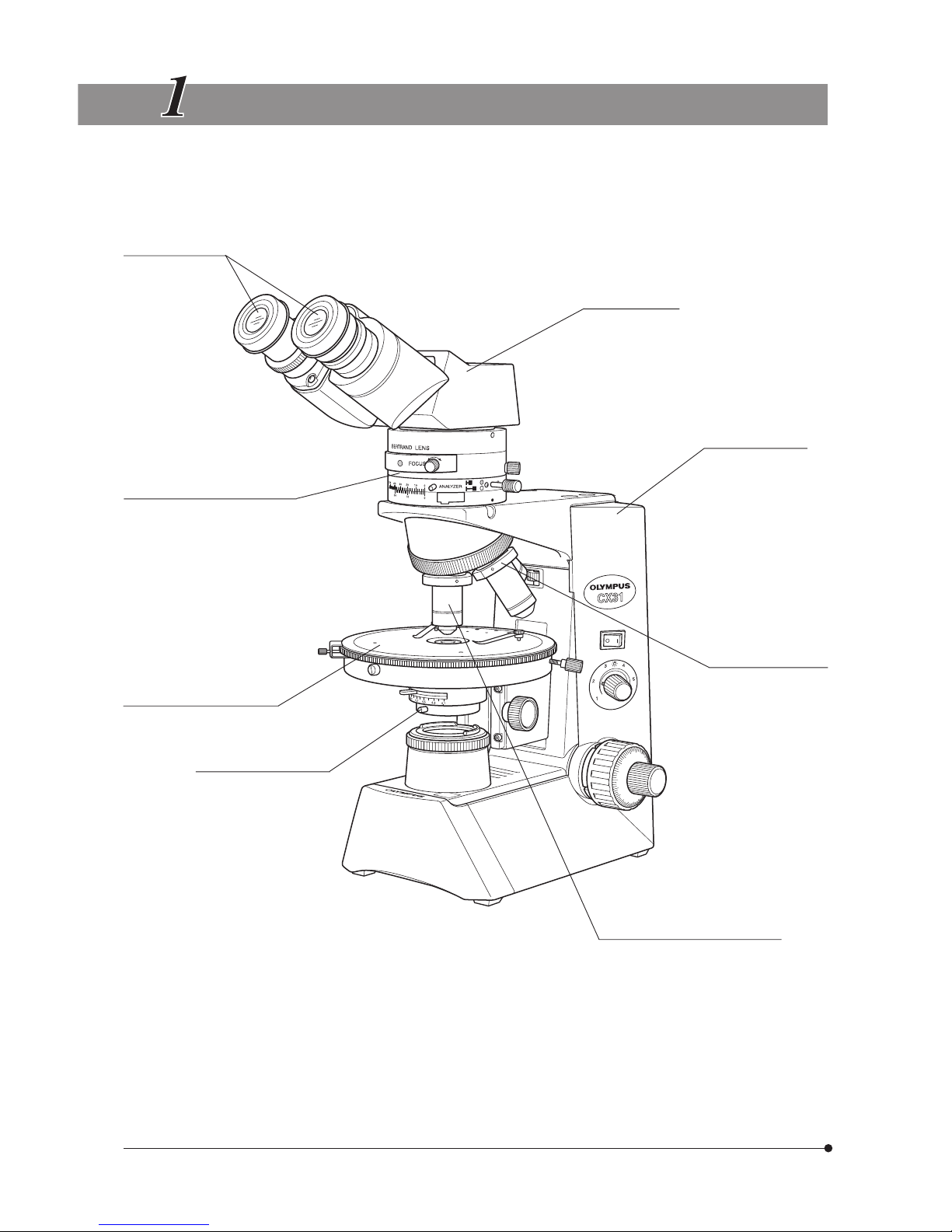
MODULE NOMENCLATURE
?The modules shown below are merely the typical examples. For other applicable modules that are not shown, please
consult the latest catalogues or Olympus.
Eyepieces
· WHN10X
· WHN10X-H
· CROSS WHN10X
· WHB10X
· WHBX10X-H
Intermediate Tube for Polarizing
Observation
·U-PA
·U-OPA
· U-KPA
Rotary stage (Not detachable)
Polarized light condenser
Observation Tube
· U-BI30P
· U-TR30-2
· U-CBI30-2
· U-CTR30-2
Microscope Frame
· CX31PF
Centering Adapter for
Objective Lens
· U-CTAD (4-piece set)
Polarized Light Objective
· PlanN4X-P
· AchN10X/20X/40X/100XO-P
}Other applicable modules
· Mechanical Stage U-FMP
· Rotary Analyzer for Polarized Light U-AN360P-2
· Sensitive Tint Plate U-TP530
· Quarter-Wave Plate U-TP137
· Test Plate Adapter U-TAD
· Transmitted Light Analyzer U-ANT
· Gout Analyzer U-GAN
· Compensators (6 models)
5
CX31-P
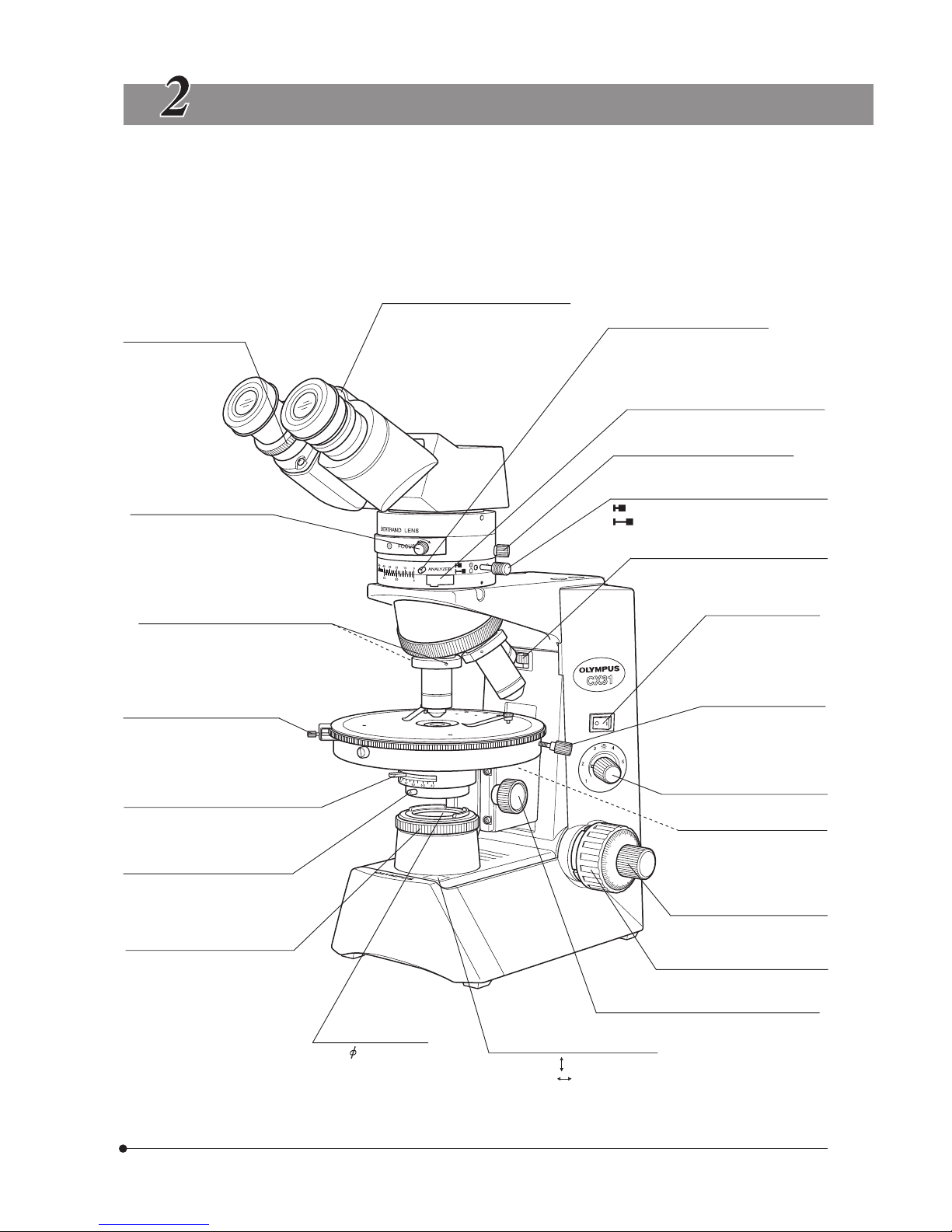
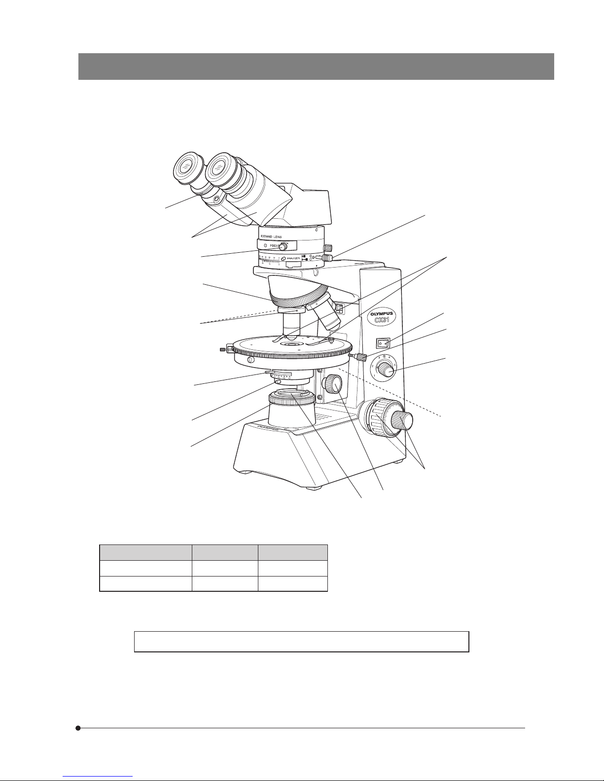
CONTROLS
}If you have not yet assembled the microscope, read Chapter 9, “ASSEMBLY” (pages 23 to 26) first.
· The illustration shows the microscope together with the U-BI30P binocular observation tube for polarizing observation
U-PA intermediate tube for polarizing observation and U-CTAD centering adapter for objective lens.
Interpupillary distance scale (Page 9)
Diopter adjustment ring
(Page 9)
Bertrand’s lens engaging/
focusing knob (Page 11)
) : IN. ( : OUT.
Objective centering screws (Page 17)
Stage rotation clamping knob
Aperture iris diaphragm lever (Page 13)
Field iris diaphragm ring (Page 8)
Test plate/compensator insertion slot
Analyzer rotation assist knob
Provided on 2 positions.
Analyzer clamping knob (Page 11)
Analyzer engaging/rotation knob (Page 11)
) : IN.
( : OUT.
Simplified pre-focusing knob (Page 9)
Main switch (Page 8)
Light intensity adjustment knob
(Page 8)
Stage centering knobs
Provided on both sides
Fine adjustment knob (Page 9)
Coarse adjustment knob (Page 9)
Condenser height adjustment knob (Page 13)
Oscillation direction indications
A : Analyzer
P : Polarizer
Filter holder
For 45 mm filters.
Polarizer rotation knob (Page 15)
Condenser centering knobs
Provided on both sides

6
SUMMARY OF POLARIZED LIGHT OBSERVATION
PROCEDURE
}This chapter describes the procedure for polarized light observation using the U-PA intermediate tube for polarizing
observation. For the procedure using the U-OPA or U-KPA, refer to the instruction manual for the intermediate tube in use.
* The operations marked * are not required when the U-CTAD centering adapter for objective lens is not used.
(Controls Used) (Page)
Set the main switch to “ I ” (ON).
Disengage the Bertrand’s lens.
Disengage the analyzer.
Place the specimen on the stage.
Engage the reference objective in the light path.
Bring the specimen into focus.
Adjust the brightness.
Adjust the interpupillary distance.
Adjust the diopter.
Adjust the analyzer and polarizer oscillation directions.
Center the reference objective.
Center the stage.
Center other objectives.
Center the field iris diaphragm.
Engage the objective to be used in the light
path, engage the analyzer and/or Bertrand’s
lens according to the purpose of observation,
and bring the specimen into focus.
Start observation.
1 Main switch (P. 8)
2 Light intensity adjustment knob (P. 8)
3
Bertrand’s lens engaging/focusing knob
(P. 11)
4 Analyzer engaging/rotation knob (P. 11)
5 Specimen holder
6 Revolving nosepiece
7
Coarse/fine focus adjustment knobs
(P. 9)
2 Light intensity adjustment knob (P. 8)
8 Binocular tube (P. 9)
9 Diopter adjustment ring (P. 9)
4 Analyzer engaging/rotation knob (P. 11)
a Polarizer rotation knob (P. 15)
b Objective centering screws (P. 17)
c Stage centering knob (P. 16)
d Field iris diaphragm ring (P. 8)
e Condenser height adjustment knob (P. 13)
f Condenser centering knob (P. 13)
b Objective centering screws (P. 17)
6 Revolving nosepiece
4 Analyzer engaging/rotation knob (P. 11)
3
Bertrand’s lens engaging/focusing knob
(P. 11)
7 Coarse/fine focus adjustment knobs (P. 9)
Adjust the aperture and field iris diaphragms.
g Aperture iris diaphragm lever (P.13)
d Field iris diaphragm ring (P. 8)
Engage the required filters. h Filter holder (P. 8)
Adjust the brightness.
2 Light intensity adjustment knob (P. 8)
*
*
7
CX31-P
4
c
2
7
1
6
5
f
d
e
a
g
b
9
3
8
Observation method Objective Bertrand’s lens
}In general biological microscopy, the analyzer,
Bertrand’s lens and test plate are not necessary and
should be disengaged from the light path.
When higher brightness is required. remove the polarizer rotation knob seat a by pulling it downward and
take out the polarizer from inside it.
Orthoscopy 4x to 100x OUT
Conoscopy 20x to 100x IN
}Make a photocopy of the observation procedure pages and post it near your microscope.
h
 Loading...