

Page 1

ISSUE 1
MAINTENANCE MANUAL
CLV-180
FR-1700
Page 2

CLV-180
INTRODUCTION
Introduction
This manual is intended for Olympus-certified technicians. Use of this manual by other individuals is
prohibited.
Precautions
Before Repair
(1) Notify the site manager of the intent to repair the unit and obtain his/her approval before
commencing.
(2) During repair, there is a risk of injury from the various tools and parts in the vicinity, as well as
from fluid leakage on the floor. Inform the relevant people to restrict access to the repair area.
(3) To prevent potentially dangerous health risks, avoid working in a closed room, i.e., select a
well-ventilated location when using organic solvents.
(4) In general, it is advisable to record the function and operation settings before repair, to enable
restoration of the settings after service.
(5) If the original settings cannot be known due to mechanical problems present at the time the unit
was accepted for repair, apply the factory-set values, or the safest settings (such as the lowest
output levels). In such a case, inform the user that the settings have been changed.
(6) Guard against static electricity.
Use a conductive mat or wristband to discharge static electricity to prevent damaging the boards
or other electrical components if it is necessary to touch them.
During Repair
(1) To prevent potentially dangerous health risks, thoroughly rinse any bodily areas that have come
into contact with organic solvents as soon as possible.
(2) When using organic solvents, handle flames such as those in alcohol lamps with caution,
because these solvents may ignite if exposed to flame.
In addition, always replace the lids back onto organic solvent containers before leaving the
work-bench.
(3) Beware of electric shock.
Turn off the power and unplug the power cord before removing the cover of the unit.
(4) Beware of residual voltages.
The unit may contain residual charges in capacitor components. Take care to avoid electric
shock when opening the top cover.
(5) To avoid personal injury and damage to the unit, heavy units should always be assembled or
disassembled by at least two people.
(6) Repair with extreme caution to avoid injury.
Use extra caution around metal parts because the edges may be sharp.
(7) Reassemble parts according to their original configuration. This regards the following items
especially:
a) Insulators, such as insulating tubes and mylar sheets.
b) Cable rerouting, clamps, and cores.
1
ISSUE1 INTRODUCTION
Page 3

CLV-180
c) Shield parts and cover screws with toothed washers.
Failure to attach parts in their original configurations, even if it does not impair product
function, poses the risk of noise radiation and reduced electrical safety.
(8) Use specified parts.
The parts and components of this product are designed to operate under certain anticipated
vibration, heat, chemical exposure, and voltage conditions. Always replace parts with those
specified in the parts list.
(9) Always tighten nuts/screws to the specified torque and only use components of the specified
dimensions.
(10) Do not reuse O-rings, E-rings, or packing. Always use new ones.
(11) When reusing components, remove sealing tape or sealing compound, and clean the
components before use.
(12) Check that no screws or nuts are loose.
After Repair
(1) After repair, inform the site manager of the nature of the problems, the cause, the
countermeasures taken, and the parts replaced.
(2) Always notify the site manager if, during repair, liquid disinfectants, cleaners, or alcohol were
used. Inform the site manager that before using the unit, it is necessary to verify the
concentration levels of disinfectants to ensure that they have not been diluted.
(3) Restore the original unit settings as they were recorded before repair. Request the presence of
site manager to verify the settings with you.
Copyright
© 2005 Olympus Medical Systems Corp. All rights reserved.
Unauthorized reproduction or distribution in part or in whole is prohibited.
Trademarks
OLYMPUS is a registered trademark of the Olympus Corporation.
The company names, product names, and proprietary technical terms in this document are the
trade-marks or registered trademarks of their respective owners.
2
ISSUE1 INTRODUCTION
Page 4

Contents
Chapter 1: Product Specifications………………………………………...1-1
1 Product Outline…………………………………..…………………………………………..1-2
2 Features……… ……… ………….……… …………..…………………… …… ……… ……..1-2
3 Operational Conditions……………………………..……………………………………...1-3
4 Specifications……… ….… ……… … …….………… ..…………………… ……… …….…1-4
5 Nomenclature and Functions…………………………………………..……………………..1-9
5-1 Front panel………………………………………………….…………………………….... 1-9
5-2 Control panel(buttons)……………………………………………………………………1-10
5-3 Control panel(indicators)………………………………………………………………...1-12
5-4 Rear and side panels……………………………………………………………………..1-14
Chapter 2: Troubleshooting………………………………………..…….2-1
1 Contents……… ……… ……… ……… ……… … ……… …………………………………… .2-2
2 Troubleshooting…………………………...…………………………………………………….2-2
2-1 Power input failure…………………………………………………………..………….2-3
2-2 Lamp failure…… ……… ……… ……… … ………… ……………………..…… …….2-4
2-3 Lamp malfunction…………….…… …… …………………….…………..… ……….2-4
2-4 Scope connection failure………………………………………………………………….2-5
2-5 High-brightness malfunction……………………………………………………………..2-6
2-6 Cooling Fan malfunction………………………………………………………………….2-7
2-7 Shield malfunction at Scope removal…………………………………………………..2-7
2-8 Pump malfunction………………………………………………………………………….2-8
2-9 Filter Change Malfunction………………………………………………………………..2-9
2-10 Outgoing light failure……………………………………………………………………2-11
2-11 Manual Brightness failure……………………………………………………………...2-11
2-12 Automatic Brightness failure………………………………………………………….2-12
2-13 Panel Malfunction……………………………………………………………………….2-13
2-14 Emergency Lamp malfunction………………………………………………………..2-15
2-15 Back-up malfunction…………………………………………………………………..2-16
2-16 Lamp Life Meter Reset malfunction…………………………………………………2-16
2-17 Transillumination malfunction……………………………………………………….2-16
Chapter 3: Precaution on disassemble and reassembly……..…..….3-1
1 Warning… … … … … … … … ..………………… … … … … … … … ..… … … ……………….3-2
2 Caution… ………… … … … … … ………… … … … … .…… … … … … … …… ………… … .3-2
Chapter 4: Assemble procedure…… ………… … ………..…..….4-1
1 Jigs and Tools………… ……… …………… …… ……………………………………… ….4-2
2 Areas…………… ………………………………………….…………………………………….4-2
3 Disassembling and Reassembling procedure……………………………………………….4-3
Chapter 5: Parts List… … ....… … … … … … … … … … ..… ..… .5-1
1 Exploded Parts Diagram…………………………..…………………………………………….5-2
2 Parts List… … … … … … … … … … … … … … .… … … … … … … … .… .… ..… … … … ..…… … … .5-10
Page 5

SpecificationCLV-180
Chapter 1: Products Specifications
ISSUE1
1-1
Page 6

SpecificationCLV-180
PRODUCT SPECIFICATIONS
1 Product Outline
Intended use:
When used in conjunction with an OLYMPUS endoscope, video system center, video monitor,
accessories, and other related equipment, this product supports examination and endoscopic treatment
by enabling observation through a fiberscope or through a video monitor.
Compatibility:
This product may be used in conjunction with EVIS 100/130/140 series videoscopes, EVIS EXERA
145/160 series videoscopes, EVIS EXERA II 165/180 series videoscopes, V series videoscopes, VISERA
series videoscopes, rigid light guides, fiberscopes, as well as EVIS EXERA II CV-180/165, and
endoscopic ultrasound systems.
Durability:
With adherance to the conditions listed below, this product has a usable life of 6 years from the
manufactured/shipped date.
Conditions: During this product’s usable life, the user must perform inspection before using, and
regular subsequent inspections as outlined in the attached materials and the operation
manual. Should the inspections reveal that repairs are required, the user must have
those repairs performed.
2 Features
(1) This is a light source unit for exclusive use with the EVIS EXERA II VIDEO SYSTEM CENTER
CV-180/165. However, this product is not to be used for surgery if used with the CV-165
(high-intensity function is not available).
(2) A mechanical detection unit is installed in the endoscope socket, enabling automatic switching to
the maximum amount of light appropriate for any endoscope connected. It is capable of
distinguishing between GI-type scope connectors, LG connectors for use with the SP high-intensity
function, and LG connectors for use with the non-SP, high-intensity function.
(3) When videoscopes or OES fiberscopes (including OES connectors used with BF and CHF type
endoscopes) are attached, the unit is capable of generating 1.3 times the output light intensity of
the CLV-U4 EVIS 100 mode and the OES mode (OAI, OLA). It produces 1.6 times more maximum
permissible illumination (white light) for the LG (non-OAI, OLA regions).
(4) When connected to a surgical fiberscope not compatible with the high-intensity RF connector, it
produces an output light intensity of the maximum permissible illumination (white light) for the LG
equivalent to the CLV-U4 EVIS 100 mode and the OES mode.
(5) When used with an endoscope and light guide compatible with the high-intensity RF connector, the
high-intensity mode is available, creating a brighter illumination. Compared to the illumination of the
CLV-U40 EVIS 100 mode or OES mode, approximately 2 times the maximum illumination (white
light) is produced. In high-intensity mode, it is also possible to select equal brightness or double
brightness of the CLV-U40 through the brightness mode switch.
(6) The optical filter used in NBI (narrowband imaging) observation has been loaded. NBI observations
are enabled when an NBI-compatible endoscope is connected to the unit.
(7) The optical filter used in PDD (photodynamic diagnosis) observation can be loaded (OE market).
One other optical filter for specialized observations may be loaded if required.
(8) The following modes may be selected:
a. Auto-ignition mode: the examination lamp automatically illuminates when the power is turned on.
b. Manual ignition mode: the examination lamp will illuminate when the lamp switch is pressed once
power has been turned on.
(9) The examination lamp can be manually turned off by continously pressing the LAMP switch for
approximately 1 second.
(10) Heat exhaust is through the rear (rear heat exhaust).
(11) The system automatically switches to the emergency lamp if the examination lamp does not come
on after pressing the lamp switch. As an emergency response, this will provide sufficient brightness
required for endoscope removal in situations when the examination lamp does not come on or if it
turns off. This will be indicated on the panel.
(12) Brightness can be adjusted using the 17 steps of automatic and manual brightness available.
(13) The air supply can be stopped completely as well as changed between high, medium or low supply.
(14) Disconnection of the emergency lamp will be automatically indicated on the panel.
(15) The transillumination switch enables the transmitted light illumination function (for GI endoscopes
ISSUE1
1-2
Page 7

SpecificationCLV-180
only).
(16) Panel settings are retained, and the light source unit will display at the previous settings the next
time the unit is turned on. However filter switch settings are not backed up, and will revert to the
regular filter.
(17) The exterior and the operating panel may be disinfected with ethanol (70% ethyl or isopropyl
alcohol) or with a mild detergent.
(18) This product has passed the OLYMPUS Eco-Product standard (Environmentally-friendly design
standard).
3 Operational Conditions
(1) Applicable video system centers: CV-180, CV-165
(2) Operational environment:
i) Use in a medical facility under the supervision of a medical doctor.
ii) Do not apply this light source directly to the heart.However, it may be used with the heart when
used in combination with a TYPE CF applied part indicated by a mark on the instrument.
iii) The outer casing of the unit must be grounded for safety.
iv) Do not use the light source in a combustible atmosphere.
v) Do not use the light source with the following electronic equipment or endoscopes:
a. Any devices designed to apply electronic treatment of a patient for which safe usage with
the CLV-180 has not yet been confirmed.
b. Any devices not designed to apply electronic treatment of a patient for which safety (e.g.,
leakage currents) has not yet be confirmed.
vi) Power supply:
Voltage: 100 – 120 V AC
Frequency: 50/60Hz
Input current: 500 VA
Power fluctuation: Within ±10%
Frequency fluctuation: Within ±1 Hz
vii) Environment
a. Operating environment
Ambient temperature: 10 – 40°C
Relative humidity: 30 – 85%
Air pressure: 700 – 1060 hPa
b. Storage environment
Ambient temperature: 25 – 70°C
Air pressure: 700 – 1060 hPa
ISSUE1
1-3
Page 8
4 Specifications
Item Specification
SpecificationCLV-180
1. Videoscopes
2. EUS Videoscopes 1. EUS 130, 140, 160 series videoscopes
4. Light guide for use
with rigid
endoscopes
5. Rigid endoscopes
(Model names
omitted)
6. High-intensity
1. Type of endoscopes
1. Compatible endoscopes
compatible
fiberscopes
(for stiff eyepiece
endoscopes)
7. High-intensity
compatible
videoscopes
Illumination light path Emergency lamp
1. Optics
2. Illumination function
1. EVIS 100, 130, 140 series videoscopes
2. EVIS EXERA 145, 160 series videoscopes
3. V series videoscopes
4. EVIS EXERA II 165, 180 series videoscopes
5. VISERA series videoscopes
1. OES 10, 20, 30, 40, 60 series fiberscopes 3. Fiberscopes
2. E, E2, E3 series fiberscopes
High-intensity compatible light guides
Note: The high-intensity mode can be set by pressing the
high-intensity mode selection switch when connecting the
light guide.
Not compatible with rigid products other than those with
high-intensity compatible light guides.
CHF-CB30L, CHF-CB30S, URF-P3
(LF-TP, LF-DP, LF-GP) *1
(ENF-GP) *2
*1 Applicable when used in combination with the following
light guides: A3290, A3291, A3292, A3293, A3294, A3295,
A3296, A3297, A3298.
*2 Applicable when using in combination with light guide
A3293.
LTF-V, LTF-V2, LTF-V3
A4940A, A4941A, A4942A, A4943A, A4800A, A4801A,
A4802A, A4803A, A4804A, A4805A, A50000A, A50001A,
A50010A, A50011A, A50020A, A50021A
Condenser lens
Optical filters
Turret board (emergency lamp, filter, etc.)
Diaphram
Light-adjustment mesh turret
(1) Each of the optical filters on the turret plate are
automatically placed in the light path according to the
normal observation mode (GI/SP), special observation
mode (GI/SP), or high-intensity mode (SP) settings.
(2) In accordance with the various observational modes
above, the mesh filter with desired aperture ratio mounted
on the mesh turret can be automatically placed in the light
path.
(3) The emergency lamp is automatically placed in the light
path when the examination lamp malfunctions.
(4) There are four special filter frames provided to enable the
use of special filters.
ISSUE1
1-4
Page 9

SpecificationCLV-180
Examination lamp
(1) Type: Xenon short arc lamp with an eliptic mirror
(2) Model: MD-631
(3) Life: 500 hours (when lit continuously)
(4) The lamp will either illuminate when the power is switched
on (auto-ignition funtion), or it can be turned on by
pressing the LAMP switch on the front panel. The lamp
can be turned off by pressing the LAMP switch
2. Illumination light
Emergency lamp
(1) Type: Halogen 35 W (with reflector)
continuously for one second.
(2) Life: Average of at least 500 hours
Method (1) Manual adjusment only for fiberscopes and rigid-type
endoscopes (excluding when used with a CV-180 and
camera head).
(2) Automatic and manual adjustment available for
videoscopes.
(3) Automatic adjustment is available when the CV-180 and
camera head are used with rigid endoscopes and
light-source cables.
NBI special observation
mode
(1) The filter mode switch enables selection of the NBI special
observation mode when a light adjustment cable and the
CV-180 are connected to an NBI-compatible endoscope.
(2) When the NBI special observation mode is selected, the
NBI special filter is placed in the illumination light path.
Note: The CV-180 power switch must be ON.
PDD normal observation
mode (OE)
PDD is option 1 for
non-OE regions
(1) PDD normal observation mode will be activated when the
light guide is connected to a light adjustment cable
equipped with the PDD function, and a camera head for
exclusive use during PDD special observation are
connected to the CV-180.
(2) During PDD normal observation mode, the PDD normal
filter is placed in the illumination light path.
2. Illumination function
Note: The CV-180 power switch must be ON.
・ The PDD normal filter and PDD special filter are
required for the PDD function.
ISSUE1
PDD special observation
mode (OE)
PDD is option 1 for
non-OE regions
3. Brightness adjustment
PDD special observation
mode (OE)
(Fiberscope)
PDD is option 1 for
non-OE regions
Optional observation
mode (OE)
PDD is option 2 for
non-OE regions
(1) From the PDD normal observation mode, the PDD special
observation mode may be selected by pressing the filter
mode switch.
(2) During PDD special observation mode, the PDD special
filter is inserted in the illumination light path.
(3) Press the switch again to insert the PDD normal filter. The
filters can be exchanged by pressing the switch.
Note: The CV-180 power switch must be ON.
(1) With the CV turned OFF, attach the light-supply cable with
the PDD function. When the light guide is attached,
pressing the filter mode switch will select the PDD special
observation mode.
(2) During PDD special observation mode, the PDD special
filter is inserted in the illumination light path.
Note: The normal filter is used for PDD observation during
observation through a fiberscope, rather than the
PDD normal filter.
(1) This function is reserved for experimental use.
1-5
Page 10
SpecificationCLV-180
available through the endoscope distal end when
High-intensity mode (1) When a high-intensity compatible endoscope is inserted, the
high-intensity mode may be selected by pressing the
high-intensity switch. High-intensity mode may not be
selected with endoscopes that are not high-intensity
compatible.
(2) When a high-intensity compatible endoscope is inserted, the
high-intensity mode switch illuminates. This enables the
selection of the high-intensity mode (LED above the switch
illuminates) or the normal mode (LED above the switch goes
out).
(3) The current settings for the high-intensity mode switch are
retained when the power is turned OFF. When a
high-intensity compatible endoscope is inserted, illumination
will either be the high-intensity mode or normal mode,
depending on the settings retained by the system. Initial
factory setting: normal mode.
(4) When the high-intensity mode is terminated (normal mode),
3. Brightness adjustment
illumination is equivalent to the CLV-U40 EVIS 100 and OES
mode.
(5) High-intensity mode provides approximately twice the amount
of illumination as the SP normal observation mode.
Manual adjustment (1) Mechanical diaphram (set on the panel)
(2) 17 steps
Automatic adjustment (1) Mechanical diaphram with constant illumination control
(image illumination)
(2) 17 steps
2. Illumination function
Front panel display
method in special
Observation mode Front panel display method
observation mode
NBI special
observation mode
・The NBI LED lights up (white)
PDD normal
observation mode
PDD special
observation mode
・The PDD LED lights up (green)
(OE only)
・The PDD LED lights up (white)
(OE only)
Equipment (1) Forced air cooling with a fan (rear exhaust)
4. Cooling
Air supply pump (1) Diaphragm system
Air supply pressure (1) Three air supply pressure levels (high, medium, low and
stop)
(2) Maximum air supply pressure: less than 53.9 kPa
Control (1) Through air supply switch settings
1. Air
Water supply (1) Supply is
a water supply container is attached.
3. Air/Water supply
function
2. Water
ISSUE1
1-6
Page 11
SpecificationCLV-180
switch)
Endoscope and light guide One-touch connection
Light-supply cable (MAJ-1411) Connector on the rear-panel
(Light-supply cable for CV connection)
Expansion cable (MAJ-202/972) System connector on the rear-panel
(compatible with Endo GATE/Endo ALPHA)
4. Connection
Foot switch (MAJ-1391) Foot switch connector on the rear-panel
Emergency lamp indicator Indicates if the emergency lamp is disconnected or if the
emergency lamp is in use (when the main lamp will not illuminate).
・Lit up: Emergency lamp in use (the main lamp will not illuminate).
・Blinking: Emergency lamp is disconnected or has been removed.
indication
5. Emergency
Setting retention (1) Settings prior to powering off the unit are retained.
・Manual / automatic brightness settings
・Airflow settings
・Light intensity level
・High-intensity mode setting
・Special observation function display
6. Panel
・Lamp life indicator (with the power ON, the indicator may
be reset when the examination lamp is extinguished by
continuously pressing the counter reset switch.)
Switch illumination system
(not including counter reset
On endoscope removal (1) When the endoscope is removed, the light emanating from
1. Dimming
Exterior
2. Disinfection
Temperature switch (1) To ensure safety, when the internal temperature rises
3. Alarm
7. Safety
Protection Class 1 unit (3P power supply)
(1) All switches illuminated
(not including counter reset switch)
the scope connector is dimmed by the dimmer plate
located in the endoscope socket.
(1) Disinfect with ethanol for disinfection (70% ethyl or
isopropyl alcohol) or with a mild detergent.
above the specified value, the temperature switch turns off
and the electrical current supply to the lamp is terminated.
The unit detects that the temperature switch has shut off,
and sounds an alarm.
ISSUE1
4. Electrical
shock
Region
1. EU/ EFTA Y
2. Japan N
regulations
5. Applicable
3. USA Y
Sold
MDD
Class:II a (rule: 11-1)
CE marking: CEO197
Pharmaceutical Law (Application of the Pharmaceutical law to assist Asian
market response)
FDC laws
1-7
Page 12
SpecificationCLV-180
4. Canada Y
5. Singapore Y
6. Other Y
Common to all
countries
Class: II
Singaporean medical device regulations
K-FDA (Korea)
SDA (China)
IEC 60601-1 (Medical electrical equipment - Part 1: General requirements
for safety): 1988 + A1, A2
IEC 60601-1-1 (Medical electrical equipment - Part 1-1: General
requirements for safety): 2000
IEC 60601-1-2 (Medical electrical equipment - Part 1-2: General
requirements for safety - Collateral standard: Electromagnetic compatibility
- requirements and tests): 2001
IEC 60601-2-18 (Medical electrical equipment - Part 2: Particular
requirements for the safety of endoscopic equipment): 1996 + A1
ISO 14971(Medical devices -- Risk management): 2000
ISO 9000-3(Software engineering -- Guidelines for the application of ISO
9001:2000 to computer software): 1997
ISO 8600-1(Optics and photonics -- Medical endoscopes and endotherapy
devices -- Part 1: General requirements): 1997
ISO 7000(Graphical symbols for use on equipment) : 2004
IEC 60417-1: 2002, -2: 1998(Graphical symbols for use on equipment)+
A1, A2
Canadian Medical Device and Equipment Regulation
EU/EFTA
EN 980 (Graphical symbols for use on equipment): 2003
2. Japan JIS T1005 (Style manual for instruction manuals): 1983
JIS T0601-1 (Medical electrical equipment -- Part 1: General requirements
for safety): 1999
6. Applicable external regulations
JIS T0601-1-1(Medical electrical equipment -- Part 1-1: General
requirements for safety -- Collateral standard: Safety requirements for
medical electrical systems): 1999
JIS T0601-1-2(Medical electrical equipment -- Part 1: General
requirements for safety -- 2. Collateral standard: Electromagnetic
compatibility -- Requirements and tests): 2002
3. USA UL 60601-1: 2003
4. Canada CAN/CSA-C22.2 No.601.1-M90: 1990
CAN/CSA-C22.2 No.601.1-S1: 1994
5. Other Olympus Eco-Product Standard
Ambient temperature 10 – 40°C
Relative humidity: 30 – 85%
Air pressure 700 to 1060hPa
Usage environment Do not use in a combustible atmosphere
Type of protection against
electrical shocks
8. Other
However, this instrument may be applied to the heart if it is used with equipment classified as
TYPE CF applied part. (indicated by the symbol)
Class 1
Degree of protection: Type BF applied part
Voltage 100 – 240 V AC
1. Usage restrictions
Frequency 50/60 Hz
Power fluctuation
Frequency fluctuation
Within ±10%
Within ±1 Hz
Power consumption 500VA
1-8
ISSUE1
Page 13
SpecificationCLV-180
User servicing Examination lamp, fuses
OLYMPUS servicing Emergency lamp replacement, special filter attachment
2. Par need replacment
Weight
Dimensions 383 (W) × 536 (D) × 162 (D) mm (maximum)
Panel Panel selection varies by region
3. Other
Power cord Cord set with a 3-prong hospital grade
Fuse Fuse capacity
Warranty period As specified in the applicable laws for each country
5 Nomenclature and Functions
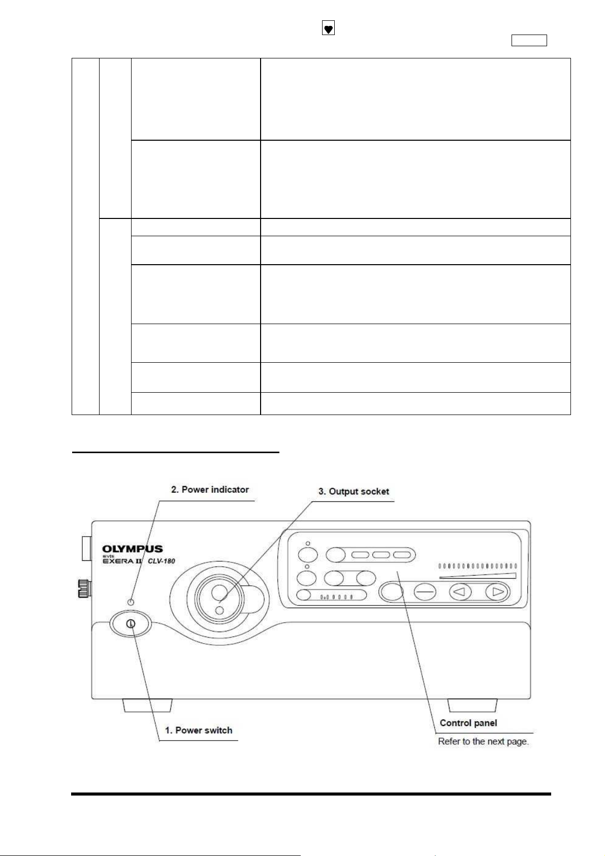
5-1 Front panel
Approximately 15.4㎏
370 () × 475 (D) × 150 (D) mm (standard)
AC 100 - 240 English (3E, 6E, 6LA)
AC 100 - 240 Symbol (6S)
AC 100 - 120 English (3OA)
AC 100 English (1J)
With plug (1J, 3OA, 3E)
Plug-less (6E, 6S,6LA)
Littel (manufacturer) 215008: 8A
ISSUE1
1-9
Page 14
SpecificationCLV-180
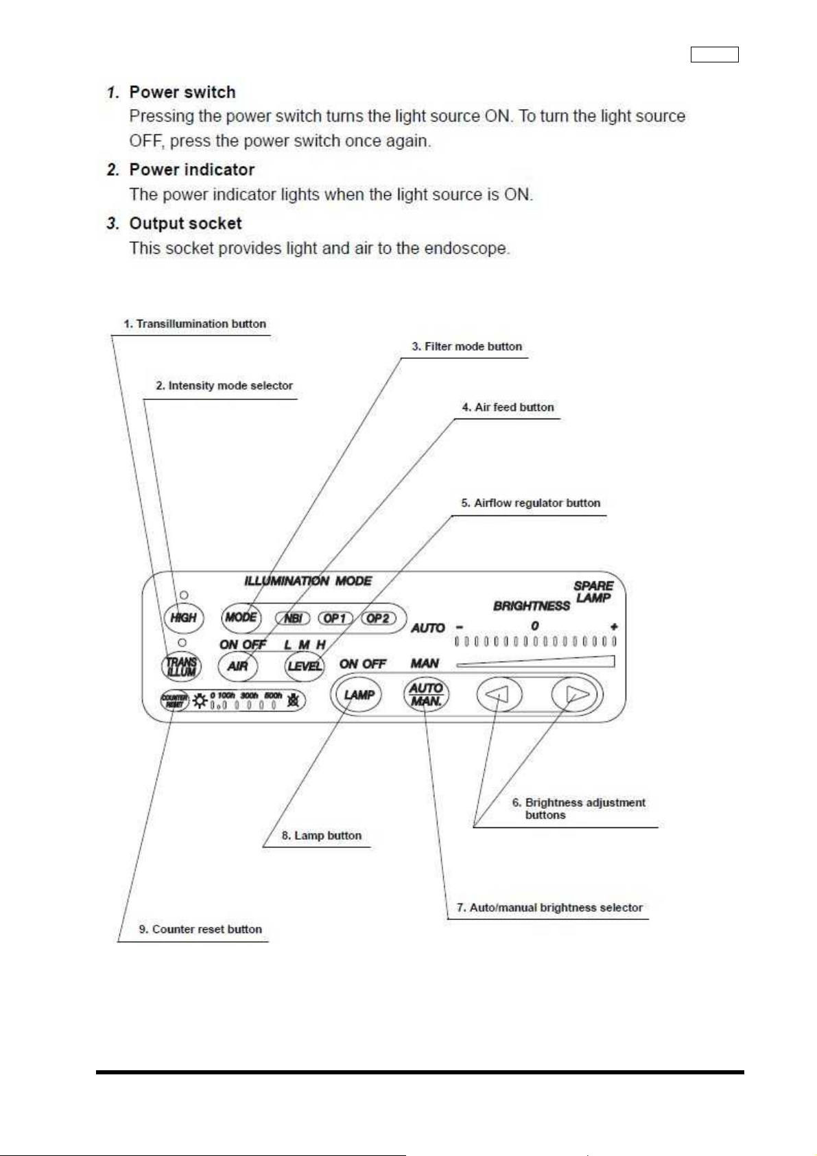
5-2 Control panel (buttons)
ISSUE1
1-10
Page 15

SpecificationCLV-180
(1) Transillumination button
When pressing this button, light emitted from the endoscope’s distal end becomes brighter for 7
seconds, then returns automatically to its original brightness level.
(2) Intensity mode selector
Press to switch between the high-intensity mode and normal intensity mode when using an
endoscope compatible with the high-intensity mode.
(3) Filter mode button
Pressing this button activates the NBI observation function.
(4) Air feed button
Pressing this button starts or stops the air feed from the endoscope’s distal end.
(5) Airflow regulator button
This button is use to control the pressure of the air being fed from the endoscope.
(6) Brightness adjustment buttons
These buttons are pressed to adjust the brightness level.
(7) Auto/manual brightness selector
This selector is pressed to select automatic or manual brightness control.
(8) Lamp button
This button is pressed to turn ON or OFF the examination (xenon) lamp.
(9) Counter reset button
After replacing the examination (xenon) lamp, the lamp hour meter is reset by pressing this button
for 1.
ISSUE1
1-11
Page 16
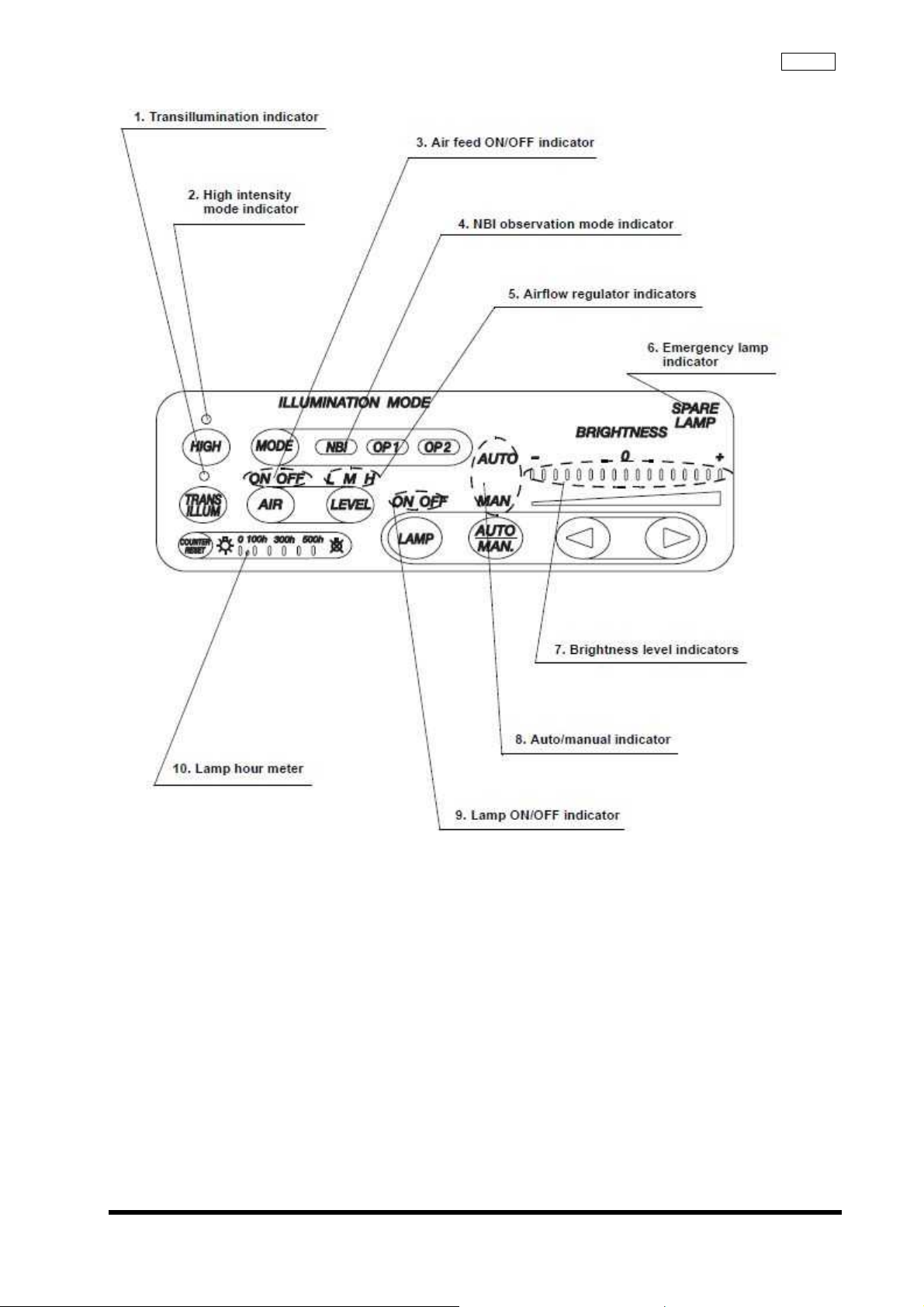
5-3 Control panel (Indicators)
SpecificationCLV-180
ISSUE1
1-12
Page 17

SpecificationCLV-180
(1) Transillumination indicator
This indicator lights when the transillumination function is activated.
(2) High intensity mode indicator
The indicator lights when high-intensity mode is selected.
(3) Air feed ON/OFF indicator
This indicator lights when the air feed from the endoscope’s distal end is activated.
(4) NBI observation mode indicator
This indicator lights in green to indicate that the light source can perform the NBI observation.
This indicator lights in green continuously when an endoscope with the NBI observation
compatibility is connected and the light source is ready for the NBI observation. Also, the indicator
lights in white when NBI observation mode is active.
The "OP.1" and "OP.2" are prepared for future use.
(5) Airflow regulator indicators
One of these indicators lights to indicate the current airflow pressure level setting ("L" (Low), "M"
(Medium) or "H" (High)).
(6) Emergency lamp indicator
This indicator lights when the emergency lamp (halogen) is in use, and blinks when the emergency
lamp (halogen) is disconnected or not mounted.
(7) Brightness level indicators
These indicators display the current brightness level.
(8) Auto/manual indicator
This indicator displays the brightness selector setting ("auto" or "manual").
(9) Lamp ON/OFF indicator
This indicator lights when the examination lamp (xenon lamp bulb) lights.
(10) Lamp hour meter
This indicator displays the total working hours of the examination (xenon) lamp.
ISSUE1
1-13
Page 18
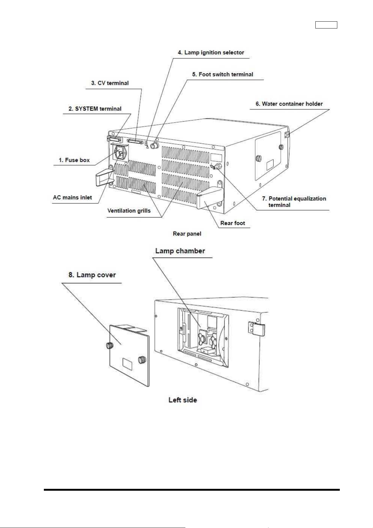
5-4 Rear and side panels
SpecificationCLV-180
1-14
ISSUE1
Page 19

SpecificationCLV-180
(1) Fuse box
The fuses protect the light source from electrical surges.
(2) SYSTEM terminal
The terminal accepts connection from an external unit.
(3) CV terminal
This terminal is the receptacle for the light source cable to connect the light source to the EVIS
EXERA II video system center.
(4) Lamp ignition selector
This selector is set to select automatic or manual ignition of the examination lamp. When the
automatic ignition is selected, turning ON the light source lights the examination lamp
simultaneously. When the manual ignition is selected, pushing the lamp button on the control panel
lights the examination lamp.
(5) Foot switch terminal
This connector is the receptacle for the foot switch (MAJ-1391) for use in the naked-eye PDD
observation.
(6) Water container holder
This holder is used for the installation of the water container.
(7) Potential equalization terminal
For safety, this terminal is connected to a potential equalization terminal of the other equipment
connected with the light source, and the electric potential of their equipment are made the same.
(8) Lamp cover
This cover has to be removed to replace the examination lamp.
ISSUE1
1-15
Page 20

Chapter 2: Troubleshooting
2-1
ISSUE1
TroubleshootingCLV-180
Page 21
TroubleshootingCLV-180
1.
Contents
Symptom Failure Mode
2-1 No power Power input failure
2-2 Xenon Lamp not lit Lamp failure
2-3 Lamp going out Lamp going out
2-4 Scope not mounting Scope connection failure
2-5 Incapability of discriminating GI, SP, or high-brightness
SP
<GI Scope>
AIR button or Transillumination button cannot be
selected when GI Scope is connected.
<SP>
AIR button, Transillumination button, and
high-brightness button can be selected when SP
Scope is connected.
<High-brightness SP>
High-brightness button cannot be selected when
high-brightness Scope and Light Guide are
connected.
2-6 Cooling fan not working Cooling fan malfunction
2-7 Exit light from Light Source when Scope is removed Shield failure at scope removal
2-8 Pump not working when Pump ON switch is pushed, or
no change in air supply volume
2-9 Turret Board not rotating when Special Light
Observation Scope is connected and Mode switch is
pushed
2-10 No light from Scope Exit light failure
2-11 View area is dark or excessively light Manual Brightness failure
2-12 View area is dark or excessively light Automatic Brightness failure
2-13 No change in LED display when switch is pushed Panel malfunction
2-14 Emergency Lamp is not automatically lit when Xenon
Lamp is put out
2-15 Values set before shutdown are not saved when power
shuts down
2-16 Time not changing to "0" when Lamp Life Meter Reset
switch is pushed
2-17 No change in light quantity when Trans Illumination
switch is pushed
Scope discrimination failure
Pump malfunction
Filter changing malfunction
Emergency Lamp malfunction
Back up malfunction
Lamp Life Meter Reset malfunction
Transillumination malfunction
2-2
ISSUE1
Page 22
2. Troubleshooting CLV-180
④
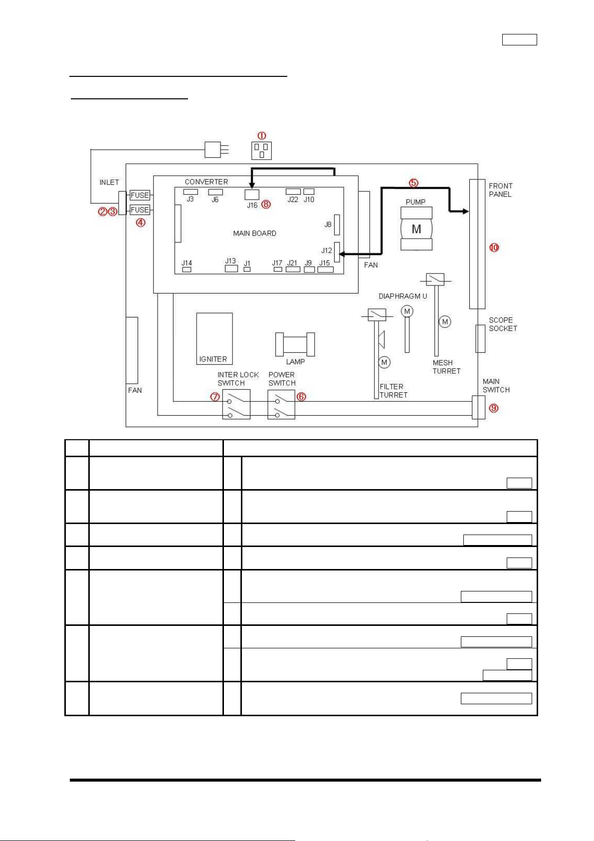
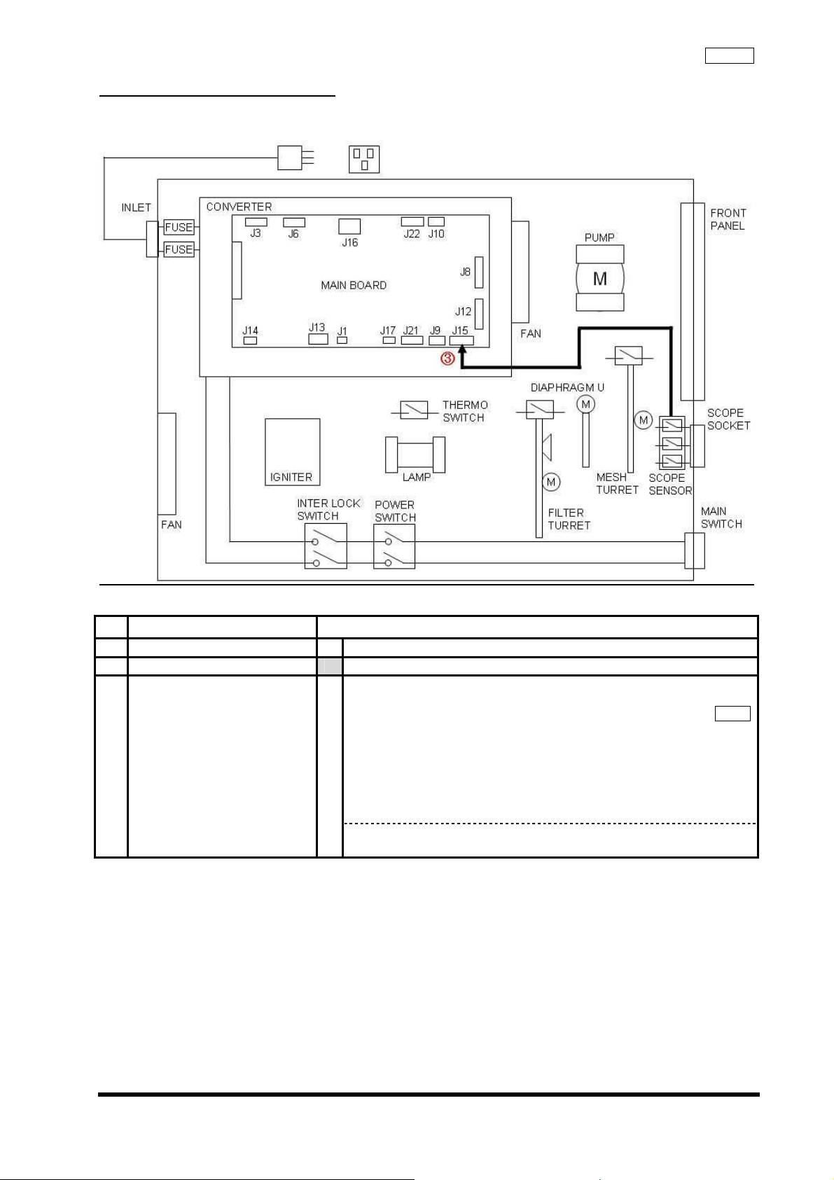
2-1 Power input failure
Incapable to input power
2-1-1 Block diagram
TroubleshootingCLV-180
2-1-2 Estimated location of failure
No
①
②
③
⑤
⑥
⑦
Estimated failure location Inspection method
Input voltage 1 Verify the voltage of wall socket.
* Conformity with commercial power voltage standard.
Power Cable 1 Connect the Power Cable to wall socket and verify voltage at inlet side.
* Conformity with commercial power voltage standard.
Body Inlet Plug 1 Confirm that the inlet plug is not bend or distorted.
Visual inspection
Fuse 1 Confirm that the fuse was not burned out.
Power Switch
Interlock Switch
Flat Cable 1 Verify connection of the Flat Cable
1 Confirm that the Power Switch inside the equipment is pushed when
the Main Switch on the Front Panel is pushed.
Visual Inspection
2 Confirm conductivity of the Power Switch when power is ON.
1 Confirm that the switch is pushed by the Lamp Door.
Visual Inspection
2 Confirm conductivity of the Interlock Switch when power is ON.
Visual Inspection
Main Board (J12) <--> Front Panel
Tester
Tester
Tester
Tester
Tester
Interlock Jig
2-3
ISSUE1
Page 23
TroubleshootingCLV-180
Main Board
⑧
Converter
Power Switch LED 1
⑨
Front Panel Unit 1
⑩
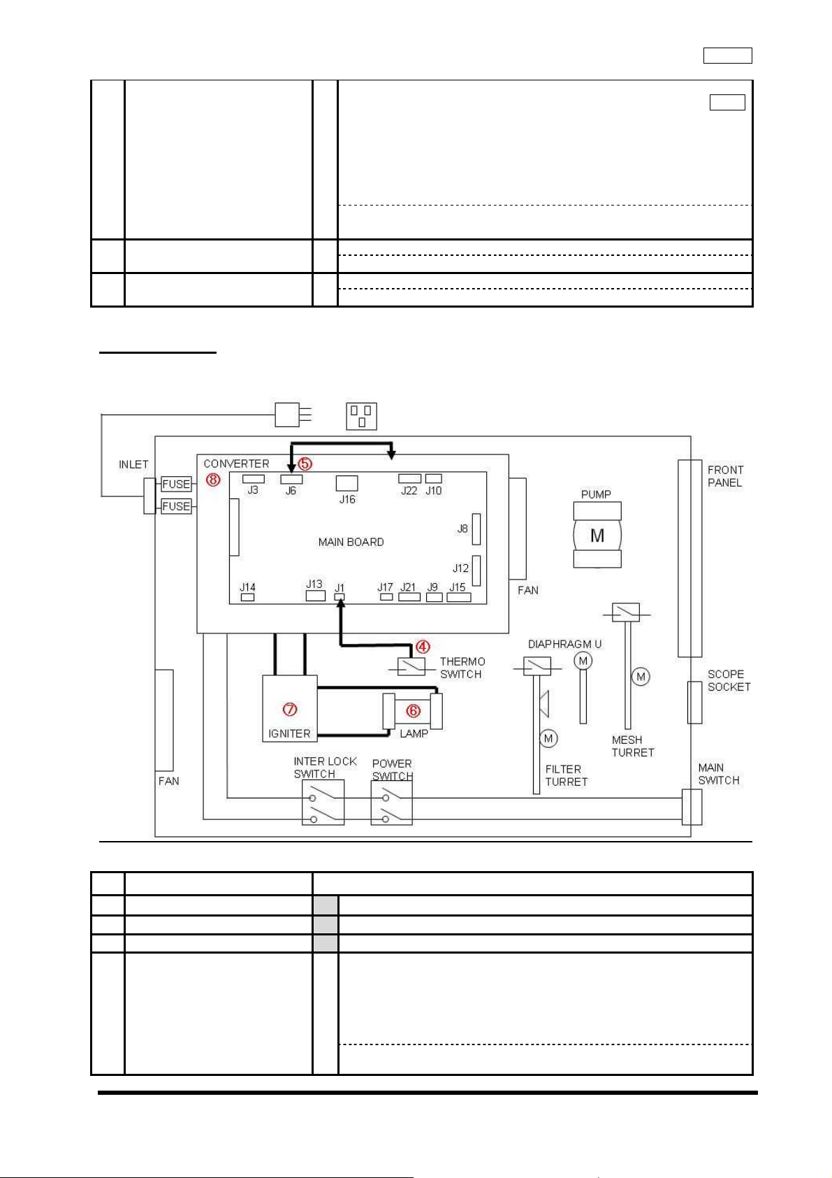
2-2 Lamp failure
Xenon Lamp of light source not lit
2-2-1 Block diagram
Confirm that the input voltage to Main Board J16 is correct.
1
J16 (Main Board) <- -> Converter)
1pin : DC +15V±0.75V
2pin : DC +12V±0.6V
3pin : DC + 5V±0.25V
4pin : GND
5pin : DC -15V±0.75V
YES → Replace Main Board
NO→ Replace Converter
Confirm that the Power Switch LED is lit:
NO → Replace the Power Switch LED
Confirm that the Front Panel of LED is lit:
NO → Replace the Front Panel
Tester
2-2-2 Estimated location of failure
No Estimated failure location Inspection method
Power input failure Refer to 2-1
①
Emergency Lamp Malfunction Refer to 2-16
②
Panel malfunction Refer to 2-13
③
Thermo Switch /
④
Main Board
ISSUE1
Status of Thermo Switch when buzzer is sounding
1
Thermo Switch
・ Less than 85℃
Conductive
・ 85℃ or higher
Non-conductive
Within standard -> Replace Main Board
Out of standard -> Replace Thermo Switch
2-4
Page 24
②
Main Board 1
⑤
Surrounding the Lamp
⑥
Xenon Lamp /
⑦
Igniter
Converter
⑧
1 Verify Lamp attachment.
2 Check the area surrounding the Lamp House.
1
1 Xenon Lamp not lit even after procedures 1-7
Confirm that the signals in the Main Board are correct:
Main Board J6/2Pin
HIGH : XENON Lamp lit*HIGH : approx. 5 V
LOW : XENON Lamp not lit
H -> L when the Ignition Button is pushed ON to turn on Lamp
L -> H when the Ignition Button is pushed OFF to turn off Lamp
(Long push)
NO →Replace Main Board
・ Confirm that Lamp is attached properly.
・ Confirm that heat compound is applied properly.
・ Confirm that the area surrounding the Xenon lamp contacts is clean.
* Cleaning is required if the discoloration is found.
・ No unnecessary objects (e.g. metal chip)
・ No leakage of high voltage pulse
・ Check connection with Terminal F and Terminal R
・ Confirm there is enough distance between Round Terminal and Lamp
House
Clattering noise at ignition
YES →Replace Xenon Lamp
NO →Igniter
YES →Replace Converter
2-3 Lamp malfunction
Lamp going out
2-3-1 Estimated location of failure
No
①
③
④
⑤
Estimated location failure Inspection method
Log 1 Verify frequency of Lamp failure errors.
* Refer to EVIS communication Checker for verification method.
CLV-180 Communication Cable
Power input failure Refer to 2-1
Emergency Lamp malfunction Refer to 2-16
Cooling Malfunction Refer to 2-6
Lamp failure Refer to 2-2
2-4 Scope connection failure
Scope not mounting
2-4-1 Estimated location of failure
No
①
②
ISSUE1
Estimated location failure Inspection Metod
Scope 1 Confirm that Scope is a compatible one.
Scope Socket 1 Confirm that the Scope Socket is free of abnormalities.
* Insert Heat Cover Positioning Jig to Scope Socket and confirm that
it's not caught inside.
2-5
TroubleshootingCLV-180
Evis communication checker
Heat Cover Positioning Jig
Page 25
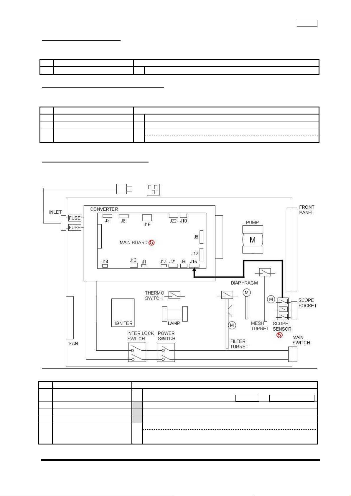
2-5 High-brightness malfunction
Not changing to high-brightness function mode
2-5-1 Block diagram
TroubleshootingCLV-180
2-5-2 Estimated location of malfunction
No
①
②
③
Estimated location failure Inspection Method
High-brightness scope 1 Confirm that scope is compatible for high-brightness.
Panel malfunction Refer to 2-13
Scope Sensor /
Main Board
Confirm following status of J15 connector on Main Board when
1
high-brightness scope is connected:
Main Board J15
When high-brightness scope is connected
Pin 2: HIGH
Pin 5: LOW
Pin 8: LOW
Pin 9: GND
* HIGH: approx. 5 V
YES → Replace Main Board
NO → Replace Scope Sensor
Tester
2-6
ISSUE1
Page 26

2-6 Cooling Fan malfunction
Cooling Fan not rotating
2-6-1 Block diagram
TroubleshootingCLV-180
2-6-2 Estimated location of failure
No
①
②
③
Estimated location failure Inspection Method
Connector 1 Verify connection of connector.
<Lamp House Fan>
Converter <--> (J16) Main Board (J14) <--> Fan
Lamp House Fan /
Main Board
Converter 1
Confirm output of +12 V at Main Board J14/Pin 1.
1
YES → Replace Lamp House Fan
NO → Replace Main Board
Confirm output of +12 V at connector of Converter Fan.
NO → Replace Converter
2-7 Shield malfunction at Scope removal
Light not changing to minimum or no change in volume when removing Scope
2-7-1 Estimated location of failure
No
①
Estimated location failure Inspection Method
Shield Plate 1
Confirm Shield Plate function.
*Insert Heat Cover Positioning Jig to Scope Socket and verify
movement of Shield Plate
NO → Replace Shield Plate
Heat Cover Positioning Jig
2-7
ISSUE1
Page 27

TroubleshootingCLV-180
2-8 Pump malfunction
No movement of the pump, or no change in air supply volume when switching the pump ON.
2-8-1 Block diagram
2-8-2 Estimated location of failure
No
①
②
③
④
Estimated location failure Inspection Method
Scope 1 Confirm that scope is compatible GI scope.
*EVIS 100,130, 160, 180 Series
Scope Sensor
Harness/
Tube
Pump 1 Confirm that air supply pressure / volume conform standards when
1 Set Pump Switch to "H".
Confirm following status of J15 on Main Board:
2
J15 on MAIN BOARD
When GI scope is connected
Pin 2: LOW
Pin 5: HIGH
Pin 8: LOW
Pin 9: GND
* HIGH: approx. 5 V
NO → Replace Scope Sensor
1 Verify Harness connection.
Main Board (J12) <--> Front Panel
2 Verify hose connection.
3 Check stuffing of Reverse Stop Valve
4 Verify rubber of Air Supply Mouthpiece.
changing air supply setting to L, M, and H.
Max pressure (at H)
53.9 kPa or less (air supply pressure locked)
Volume
L: 0.5 L/min or more (output pressure: set as 19.6-20.6 kPa)
M: 0.68 L/min or more (output pressure: set as 21.6-22.6 kPa)
H: 1 L/min or more (output pressure: set as 26.5-27.5 kPa)
Air Flow Checker
2-8
ISSUE1
Page 28

TroubleshootingCLV-180
⑤
Main Board /
Pump
Confirm that the output voltage of Main Board J17/Pin 1 conforms to
1
standards when changing air supply setting to L, M, and H.
Main Board J17/Pin 1
Air supply level: Output voltage
L: +5 V
M: +8 V
H: +12 V
YES → Replace Pump
NO→ Main Board
2-9 Filter Change Malfunction
Turret Board not rotating when Mode Switch is pushed
2-9-1 Block diagram
2-9-2 Estimated location of failure
No
①
②
③
④
⑤
⑥
ISSUE1
Estimated location failure Inspection Method
Light Source Cable 1 Verify connection of CV and Light Source Cable (MAJ-1411).
Scope /
Camera Head
Panel Lamp failure 1 Refer to 2-13
Harness 1 Verify connection of Harness.
Filter Limit Switch 1
Mesh Limit Switch 1
1 Confirm that scope or camera head is compatible with special light.
Main Board (J22) <--> Mesh Turret Unit
Main Board (J21) <--> Filter Turret Unit
Main Board (J10) <--> Mesh Limit Switch Unit
Main Board (J9) <--> Filter Limit Switch Unit
Main Board (J12) <--> Front Panel
Confirm that J9/Pin 1 change to LOW when Filter Limit Switch is
pushed.
NO → Replace Filter Limit Switch
Confirm that J10/Pin 1 change to LOW when Mesh Limit Switch is
pushed.
NO → Replace Mesh Limit Switch
2-9
Visual Inspection
Visual Inspection
Page 29

TroubleshootingCLV-180
Filter Turret Unit /
⑦
Main Board
1 Enter Brightness Manual Mode.
Input power by pushing "AIR Switch" and "Brightness UP Switch".
Set Filter position at will through MODE Switch and generate control
2
signal through AIR Switch. Then confirm following wave form at J21 of
Main Board:
Oscilloscope
J21 Connector
Pin 1:φ1
Pin 2:φ2
Pin 5:φ3
Pin 6:φ4
Mesh Turret Unit /
⑧
Main Board
(Range:5 V 10 ms)
YES → Filter Turret Unit
NO → Main Board
1 Enter Brightness Manual Mode.
Input power by pushing "AIR Switch" and "Brightness UP Switch".
Set Filter position at will through Counter Reset Switch and generate
2
control signal through AIR Switch. Then confirm following wave form at
J22 of Main Board:
Oscilloscope
J22Connector
Pin 1:φ1
Pin 2:φ2
Pin 5:φ3
Pin 6:φ4
(Range:5 V 10 ms)
YES → Mesh Turret Unit
NO → Main Board
2-10
ISSUE1
Page 30

2-10 Outgoing light failure
④
No light going out from Scope
2-10-1 Estimated location of failure
No
①
②
③
④
⑤
Estimated location failure Inspection Method
Scope 1 Confirm that Scope is a compatible one.
Power input failure Refer to 2-1
Lamp failure Refer to 2-2
Filter change malfunction Refer to 2-9
Manual Brightness failure Refer to 2-11
2-11 Manual Brightness failure
View field is dark or excessively light.
2-11-1 Block diagram
TroubleshootingCLV-180
2-11-2 Estimated location of failure
No
①
②
③
ISSUE1
Estimated location failure Inspection Method
Harness 1 Verify connection of Harness.
Main Board (J12) -> Front Panel
Main Board (J8) -> Iris Unit
Panel light malfunction Refer to 2-13
Iris Unit 1 Confirm that Iris Unit is mounted without distortion or inclination.
Iris Wing Positioning Jig
Scope Sensor 1 Confirm the following status of Main Board at J15 when Scope Dummy
is connected to Scope Socket:
・GI ScopeGI Scope Dummy
J15
Pin 2:L
Pin 5:H
Pin 8:L
・SP ScopeHeat Cover Positioning Jig
Pin 2:L
Pin 5:L
2-11
Page 31

Pin 8:H
・High-brightness SP ScopeHigh brightness SP Scope Dummy
Pin 2:H
Pin 5:L
Pin 8:L
*H:approx. 5 V
NO:Replace Scope Sensor
⑤
Iris Unit /
Main Board
Confirm following status of J8 when Brightness is set to manual and
1
light quantity from minimum to maximum:
J8
Pin 2 :Voltage change minus to plus.
YES:Replace Iris Unit
NO :Replace Main Board
2-12 Automatic Brightness failure
View field is dark or excessively light
2-12-1 Estimated location of failure
No
1 Light Source Cable
2 Manual Brightness failure Refer to 2-11
3 Main Board
Estimated location failure Inspection Method
Confirm connection to system capable of automatic Brightness.
CV-180
Confirm following status of J8 when scope move to the distance from
vicinity:
J8
Pin 2 :Voltage change minus to plus.
TES :Replace Iris Unit
NO:Replace Main Board
TroubleshootingCLV-180
CV-180
Light Source Cable
2-12
ISSUE1
Page 32

2-13 Panel Malfunction
@ No change in LED when switch is pushed, or LED display not lit.
@ The whole Front Panel blinks not accepting buttons.
2-13-1 Block diagram
TroubleshootingCLV-180
2-13-2 Estimated location of failure
No
1 HARNESS
3 MAIN BOARD
Estimated location failure Inspection Method
HARNESS
FRONT PANEL
1 Verify connection of Harness.
Main Board (J12) -> Front Panel
LED not completely lit when POWER is switched ON. 2 FRONT PANEL
1
No LED lit : Replace Harness
Some LED lit : Replace Front Panel
1 Confirm that the Pin corresponding to Main Board J12 change to H
when button is pushed.
*H: approx. DC +5 V
Tester
J12
Pin 5 :AIR
Pin 6 :MODE
Pin 7 :AUTO/MANUAL
Pin 8 :BRIGHTNESS UP
Pin 9 :BRIGHTNESS DOWN
Pin 10:LEVEL
Pin 11:TRANSILLUMINATION
Pin 12:LUMP
Pin 13:COUNTER RESET
Pin 14:HIGH
2-13
ISSUE1
Page 33

TroubleshootingCLV-180
4
SCORP SENSOR
THERMO SENSOR
MAIN BOARD
YES : Replace MAIN BOARD
NO : Replace FRONT PANEL
Front Panel blinks immediately after switching Power ON not accepting
1
buttons.
・ Pin of Thermo Sensor not conductive:
Replace Thermo Sensor
Signals from Scope Sensor are not the following when each type of
scope is connected to Scope Socket:
Replace Scope Sensor
Main Board J15
・GI Scope GI Scope Dummy
J15
Pin 2:L
Pin 5:H
Pin 8:L
・SP ScopeHeat Cover Positioning Jig
Pin 2:L
Pin 5:L
Pin 8:H
・High brightness SP ScopeHigh brightness SP Scope Dummy
Pin 2:H
Pin 5:L
Pin 8:L
*H:approx. 5 V
・ None of the above cases applicable: Replace Main Board
2-14
ISSUE1
Page 34

2-14 Emergency Lamp malfunction
Emergency Lamp not lit automatically when Xenon Lamp is off.
2-14-1 Block diagram
TroubleshootingCLV-180
2-14-2 Estimated location of failure
No
①
②
③
④
Estimated location failure Inspection Method
EMRGENCY LAMP
HARNESS
Panel malfunction Refer to 2-13
Filter change malfunction Refer to 2-9
CONVERTER
MAIN BOARD
Confirm that Emergency Lamp on Front Panel is blinking.
1
YES : Replace EMRGENCY LAMP
Replace HARNESS(CONVERTER → EMERGENCY LAMP)
Confirm status of following pins at Main Board J6 when Emergency
1
Lamp is not blinking:
・(When Xenon Lamp is OFF)
2 : H(Xenon Lamp ON order: ON order at L. L maintain while ON)
3 : H(Emergency Lamp ON: L when ON)
6 : H(Xenon Lamp ON: L when ON)
7 : L(Emergency Lamp: L when no break down)
Replace MAIN BOARD
・(When Emergency Lamp is ON)
2 : H
3 : L
6 : H
7 : L
Replace CONVERTER
・(When Xenon Lamp is working normally)
2 : L
3 : H
6 : L
7 : L
Replace CONVERTER or MAIN BOARD
・Others
Replace CONVERTER or MAIN BOARD
2-15
ISSUE1
Page 35
2-15 Back-up malfunction
②
Settings are not saved after switching Power OFF
2-15-1 Estimated location of failure
No
①
Estimated location failure Inspection Method
MAIN BOARD 1 Replace MAIN BOARD
2-16 Lamp Life Meter Reset malfunction
Not changing to "0" when Lamp Life Meter Reset switch is pushed.
2-16-2 Estimated location of failure
No
①
②
③
Estimated location failure Inspection Method
XENON LAMP 1 Confirm that Xenon Lamp is OFF.
Panel malfunction Refer to 2-13
MAIN BOARD
Dose not reset when pushing Reset switch.
YES : Replace MAIN BOARD
2-17 Transillumination malfunction
No change in light quantity when Transillumination switch is pushed.
2-17-1 Block diagram
TroubleshootingCLV-180
2-17-2 Estimated location of failure
No
①
③
④
⑤
ISSUE1
Estimated location failure Inspection Method
Scope 1 Confirm that GI Scope is connected.
Panel Malfunction Refer to 2-13
Filter Change Malfunction Refer to 2-9
Manual Brightness malfunction Refer to 2-11
SCOPE SENSOR
MAIN BOARD
Transillumination switch lit:
NO → SCORP SENSOR 交換
YES → MAIN BOARD
2-16
GI Scope or GI Scope Dummy
Page 36

Precautions on disassembly and assembly CLV-180
Chapter 3: Precaution on
disassembly and reassembly
ISSUE 1
3-1
Page 37

Precautions on disassembly and assembly CLV-180
1. Warning
(1) To prevent potentially dangerous health risks, select a well-ventilated location when using organic solvents.
(2) To prevent potentially dangerous health risks, rinse your body well under running water to wash away
organic solvents if any adhere to your body.
(3) When using organic solvents, handle flames such as those in alcohol lamps with caution since these
solvents may ignite if exposed to flame. In addition, be sure to put the lids on containers of organic solvents
before leaving the workbench.
2. Caution
(1) Attach parts in their original configurations during reassembly. Pay particularly close attention to the following
items:
a) Insulators, such as insulating tubes and mylar sheets
b) Cable rerouting, clamps, and cores
c) Shielded parts and covered screws with toothed washers
Failure to attach parts in their original configurations, even if it does not impair
product functions, poses the risk of noise radiation and reduced electrical safety.
(2) Exercise extreme caution to prevent possible injuries during reassembly. Be particularly careful to avoid
injuring yourself on the sharp edges of metal parts.
(3) Always use the specified components. The product is comprised of components designed to withstand
anticipated vibration, heat, and voltage. When replacing any component, make sure the replacement
component has the same characteristics as the original component, and always use the specified
components.
(4) Use the specified jigs and tools. The use of any unspecified jigs or tools may damage the AR-TZ2 or the
components under repair and prevent it from functioning properly or performing optimally.
(5) Be careful to avoid electrocution. Only remove the cover enclosing the OTV-SP1C after turning off the power
and unplugging the power cord, unless it is critically important not to do so.
(6) Be careful about residual voltage. Even if the unit is turned off before the cover is opened, keep in mind that
the capacitor may still hold a charge, so take care to avoid electrocution.
(7) Guard against static electricity. If it is necessary to touch the boards or other electrical components, to
prevent damaging them, use a conductive mat or wristband to discharge static electricity.
ISSUE 1
3-2
Page 38

Disassembly and Reassembly ProcedureCLV-180
Chapter 4: Disassembly and
Reassembly procedure
ISSUE1
4-1
Page 39

1. Jigs and Tools
No. Name Specification Remark
1 Box bit Size 5.5 mm
2 Phillips bit (No1)
3 Phillips bit (No2)
4 Open head 10 mm, 14 mm
5 Torque driver 0.02~0.15 [Nm]
6 Torque driver 0.2~1.2 [Nm]
7 Torque driver 0.6~2.6 [Nm]
8 Long-nose Pliers
9 Nipper
10 Tweezers
11 Filter retaining jig
12 Diaphragm positioning jig
13 Heat cover positioning jig
2. Areas
Disassembling procedure is described by 3 areas.
Disassembly and Reassembly ProcedureCLV-180
ISSUE1
A
B
C
4-2
Page 40

Disassembly and Reassembly ProcedureCLV-180
3. Disassembling and Reassembling procedure
3-1 First step
DOOR 260 EU
3-2 Area A
TOP COVER
13 screws
W03O002A
(Thermo switch)
1 screw 2 screws
Shield plate
Switch board collar
Switch board
Switch washer
2 screws
3-2-1 NSW bracket
Switch board spring
NSW bracket U
[3-2-1]
Heat sink eco U
[3-2-2]
3 screws
Switch
(interlock)
Rear panel U
[3-2-3]
11 screws 6 nuts
Shield case 260 eco U
[3-2-4]
W03O003A
(FAN)
2 screws
Lamp base U
[3-2-5]
4 nuts
Igniter U
[3-2-6]
3 nuts
Igniter COVER
2 nuts
1 screw
W03O018A
(Main switch)
Extending knob
ISSUE1
4-3
Page 41

3-2-2 Heat sink eco U
Disassembly and Reassembly ProcedureCLV-180
Sink shaft
1 e-ring
Hinge board
Spring collar
2 screws
Magnet holder eco
Magnet
2 screws
Snap lock
Mini catch
6 screws
GT washer
Xenon lamp
Hex bolt
3-2-3 Shield case 260 eco U
SHIELD MYLAR 1
Knob washer
SHIELD MYLAR 2
HS guide x 2
4 screws
Gasket 2
Caution plate
Mini clamp
Cable holder
ISSUE1
4-4
Page 42

3-2-4 Lamp base U
Disassembly and Reassembly ProcedureCLV-180
Sink retainer spring
2 screws
Pole spacer
Pole F
1 screw
Discharge spring
W12M020A
(resistance)
1 screw
Discharge plate
W12M019A(cable)
1 screw
3-2-5 Igniter U
UPCL16PS50
(Igniter)
Igniter BL
Pole R
3 screws
Sink spring
2 screws
Discharge coil
Discharge base U
1 e-ring
W03O001A
(CONDENSER H)
Sink spring
2 screws
Discharge spindle
Discharge base
1 screw
Core x 2
2 binders
ISSUE1
3 nuts
W03O006A
(+IGNITER H)
W03O007A
(-IGNITER H)
W03O008A
(+RELAY H)
W03O009A
(-RELAY H)
4-5
Page 43

3-3 Area B
Disassembly and Reassembly ProcedureCLV-180
6 screws
3-4 Area C
Front panel
[3-4-1]
3 screws
M limit SW U
IPF Power supply U MAIN BOARD
4 nuts
S socket U
[3-4-3]
4 screw
M turret U
Side clamp
Connector cover
Terminal
Binder
180 MESH BK BASE
2 screws
Pump 260 eco U
[3-4-2]
4 nuts
Turret U
[3-4-4]
4 screws
W04Q001A
(scope detection cable )
W03Q011A
(filter turret cable )
W03Q011A
(filter turret cable )
4 screws
W03Q011A
(filter turret cable )
Limit SWBK eco U
1 screws
Lens retainer U
2 screws
4 screws
ISSUE1
UPNS180U
(Diaphragm)
2 screws
4-6
Page 44

3-4-1 Front panel U
6 screws
180 FP chassis
Disassembly and Reassembly ProcedureCLV-180
Binder
(Cord holder)
180 shielding plate
4 screws
FP sheet
5 screws
Gasket F 260
Core holder 180
2 screws
3-4-2 Pump 260 eco U
Upper P case
4 screws
F panel 180 U
Core
Binder
P packing
Pump U
2 screw
Pump
UPCL18ZZ
(LED Board)
1 screw
Switch collar LL
Switch spring
Main switch
Valve U
Pump board eco
Rubber foot
Tubes
Pump base
4-7
ISSUE1
Page 45

3-4-3 S socket U
Disassembly and Reassembly ProcedureCLV-180
Heat cover
2 screws
SS board repair U
1 screw 2 screws
Plastic screw
3-4-4 Turret U
Cramp base eco
2 screws
F frame board
2 screws
Attachment U
Retaining bracket 180
Turret BK eco U
1 screw
Binder
1 screw
Hinge 180
2 screws
Edge saddle
1 screw
Slide detection spring
Slide detection 180
T stopper pin
1 screw
H lamp shield
2 screws
H lamp retainer
3 screws
Filters
3-4-4 Turret U
5 screws
W03O010A
(Lamp harness)
H Lamp spring
Emergency lamp
M turret repair U T stopper pin 180
1 screw
Limit SW U
4-8
ISSUE1
Page 46

3-1 First step
Disassembly and Reassembly ProcedureCLV-180
(1) Loosen the knot and take off 260EU
260EU
SWITCH
BLOCK
WRENCH
TOP COVER
C6N3SZ
(2) Take off WRENCH
(3) Take off 2 NUTS (C6N3SZx2) and SWITCH BLOCK
BOX bit(size 5.5 mm)
Torque driver
Tightening torque 0.6 Nm
(4) Take off 13 SCREWS (HCBK3x6SAx10: 10 on the
right and left side、3 on the back) and TOP COVER
→3-2 Area A
→3-3 Area B
→3-4 Area C
Phillips bit (No.2)
Torque driver
Tightening torque 0.6 Nm
3-2 Area A
CUKSK3X6SZ
THERMO SWITCH
ISSUE1
(1) Take off 1 SCREW (CUKSK3X6SZ) and THERMO
SWITCH
Phillips bit (No.2)
Torque driver
Tightening torque 0.6 Nm
4-9
Page 47

Disassembly and Reassembly ProcedureCLV-180
Blue
CCUK3x4SZ
HEAT SINK U
Green
(2) Take off only junction part of FASTEN TERNMINAL
(3) Take off 2 SCREWS (CCUK3x4SZx2) and NSW
BRACKET U
Phillips bit (No.2)
Torque driver
Tightening torque 0.6 Nm
(4) Take off HEAT SINK U
→Go to 3-2-2
CBK2.5x6SA HCBK3x6SA
REAR PANEL U
C6N3SZ
CCUK3X4SZ
SHIELD PLATE
(5) Take off 9 SCREWS (HCBK3x6SA:7, CBK2.5x6SA:2)
and REAR PANEL U
→Go to 3-2-3
Phillips bit (No.1)
Torque driver
Tightening torque 0.33 Nm
Phillips bit (No.2)
Torque driver
Tightening torque 0.6 Nm
(6) Take off 3 SCREWS (CCUK3X4SZ) and SHIELD
PLATE
Philips bit (No.2)
Torque driver
Tightening torque 0.6 Nm
(7) Take off 6 NUTS (C6N3SZ) and SHIELD CASE 260 U
→Go to 3-2-4
Box bit(Size 5.5 mm)
Torque driver
(Tightening torque:0.6 Nm)
4-10
ISSUE1
Page 48

Disassembly and Reassembly ProcedureCLV-180
CUKSK3x6SZ CUKSK4x6SZ
(10) C6N3SZ
IGNITER
COVER
(9) C6N3SZ
IGNITER U
(8) Take off 2 SCREWS (CUKSK3x6SZ, CUK¥SK4x6SZ) ,
and adjust HARNESS which is connected with LAMP
BASE U
Phillips bit (No.2)
Torque driver
Tightening torque 0.6 Nm
(9) Take off 2 NUTS (C6N3SZ) and IGNITER COVER
Box bit (Size 5.5 mm)
Torque driver
(Tightening torque:0.6 Nm)
(10) Take off 3 NUTS (C6N3SZ) and IGNITER U
*At same time, take off HARNESS from POWER
SUPPLY
→Go to 3-2-6
Box bit (Size 5.5 mm)
Torque driver
(Tightening torque:0.6 N m)
Connected with HARNESS Take off HARNESS
C6N3SZ
LAMP BASE U
Connected with HARNESS
ISSUE1
(11) Take off 5 NUTS (C6N3SZ) and LAMP BASE U
*One of NUTS is connected with HARNESS
→Go to 3-2-5
BOX bit(size 5.5 mm)
Torque driver
Tightening torque0.6 Nm
4-11
Page 49

Disassembly and Reassembly ProcedureCLV-180
(15)CCUK4x45SZTake off CONNECTOR
FERRITE CORE
FAN BK
ECO
CORE
STAND
(14)CCUK3x4SZ (13)C6N3SZ (16)CUKSK3x6SZ
3-2-1 NSW bracket
CCUK3x4SZ
INTERLOCK
SWITCH
EXTENDING
KNOB
MAIN SWITCH
3-2-2 Heat sink eco U
(12) Take off FAN CABLE from J14 of MAIN BOARD
(13) Take off 1 NUTS (C6N3SZ) and FERRITE CORE
BOX bit(size 5.5 mm)
Torque driver
Tightening torque 0.6 Nm
(14) Take off 2 SCREWS (CCUK3x4SZ) and FAN ECO U
Phillips bit (No.2)
Torque driver
Tightening torque 0.6 Nm
(15) Take off 2 SCREWS (CCUK4x45SZ) and FAN BK
ECO
Phillips bit (No.2)
Torque driver
Tightening torque 1.4 Nm
(16) Take CORE out and take off SCREW (CUKSK3x6SZ)
and CORE STAND
Phillips bit (No.2)
Torque driver
Tightening torque 0.6 Nm
(1) Take off 1 SCREW (CCUK3x4SZ) and SW PLATE
SPRING
Phillips bit( No.2 )
Torque driver
Tightening torque 0.6 Nm
(2) Take off EXTENDING KNOB from MAIN SWITCH
(3) Take SWITCH (INTERLOCK SW)and MAIN SWITCH
from N SWITCH BK
*Take off by pushing the trap on each upper and
lower side
(1) Unlock HEAT SINK F ECO U
4-12
ISSUE1
Page 50

CCUK3x6SZ
WASHER
KNOB WASHER
ER5SA
Disassembly and Reassembly ProcedureCLV-180
(2) Take off ER5SA from SINK SHAFT in HEAT SINK F
ECO U
Long-nose Pliers
(3) Pull SINK SHAFT, then take off KNOB WASHER
from SINK SHAFT
(4) Take off 2 SCREWS (CCUK3x6SZ), HINGE PLATE
and SPRING COLLAR
Phillips bit (№2)
Torque driver
Tightening torque 0.6 Nm
(6)CSK2.5x6SA
SNAP
LOCK
XENON LAMP
MINI CATCH
(5)CSK2.5x6SA
GT
(5) Take off 2 SCREWS (CSK2.5x6SA), MAGNET
HOLDER ECO and MAGNET
Phillips bit (№1)
Torque driver
Tightening torque 0.33 Nm
(6) Take off 6 SCREWS (CSK2.5x6SA) , SNAP LOCK
and MINI CATCH
Phillips bit (№1)
Torque driver
Tightening torque 0.33 Nm
(7) Take off 3 HEX BOLT, GT WASHER and XENON
LAMP
Hex wrench(size 2.5 mm)
Tightening torque 0.8 Nm
HEX BOLT
(8) SINK SHAFT Take off ER5SA from SINK SHAFT
on HEAT SINK F ECO U
Long-nose Pliers
(9) Pull SINK SHAFT, and take off KNOB
WASHER from SINK SHAFT
ER5SA
KNOB WASHER
4-13
ISSUE1
Page 51

3-2-3 Rear panel
(1)
(3)
CCUK2.5x6SZ
(2)
RETAINING
BASE
(5)
6N6SN
EndoAlpha
CONNECTOR
(4)
FOOT SW
CONNECTOR
TERMINAL
REAR
FOOT
Disassembly and Reassembly ProcedureCLV-180
(1) Take off NUT, WASHER and FOOT SW CONNECTOR
Open head (size 14 mm)
Torque driver
Tightening torque 1.2 Nm
(2) Take off 1 NUT(C6N3SZ) and GROUND CODE, and 1
WASHER
BOX bit (size 5.5 mm)
Torque driver
Tightening torque 0.6 Nm
(3) Take off 2 SCREWS (CCUK2.5x6SZ), EndoAlpha
CONNECTOR and RETAINING BASE
Phillips bit (№2)
Torque driver
Tightening torque 0.4 Nm
(4) Take off 4 SCREWS(CBK3x4SA) and REAR FOOT
Phillips bit (№2)
Torque driver
Tightening torque 0.6 Nm
(5) Take off 2 NUTS(6N6SN), 1 WASHER and TERMINAL
Open head(size 10 mm)
Torque wrench
Tightening torque 5 Nm
4-14
ISSUE1
Page 52

3-2-4 Shield case 260 eco U
CCUK3x6SZ
CCUK3x6SZ
CCUK3x6SZ
CABLE HOLDER
CAUTION PLATE
Disassembly and Reassembly ProcedureCLV-180
(1) Take off GASKET 2
(2) Take off CABLE HOLDER
(3) Take off MINI CLAMP
(4) Take off CAUTION PLATE
MINI
CLAMP
GASKET 2
SHIELD MYLAR 2 CCUK3x6SZ
SHIELD MYLAR 1
3-2-4 Lamp base U
(1)
(2)
(3)
(5) Take off 4 SCREWS(CCUK3x6SZ), HS GUIDE
Phillips bit (№2)
Torque driver
Tightening torque 0.6 Nm
(6) Take off SHIELD MYLAR 1
(7) Take off SHIELD MYLAR 2
(1) Take off 2 SCREWS(CCUK3x6SZ) and take off SINK
SPRING from POLE F
Phillips bit (№2)
Torque driver
Tightening torque 0.6 Nm
(2) Take off 2 SCREWS(CCUK3x6SZ) and take off SINK
SPRING from POLE R
Phillips bit (№2)
Torque driver
Tightening torque 0.6 Nm
(3) Take off 3 SCREWS (CCUK3x6SZ)
Phillips bit (№2)
Torque driver
Tightening torque 0.6 Nm
4-15
ISSUE1
Page 53

CCUK3x6SZ
SPRING
CCUK3x6SZ
CCUK2x4SZ
PLATE
DISCHARGE COIL
POLE SPACER
HARNESS
DISCHARGE
ISSUE1
(5) (6)
(8)
DISCHARGE
(10) ER2.5SN
(4)
(11)
DISCHARGE
COIL
(9)
Disassembly and Reassembly ProcedureCLV-180
(4) Take off 1 SCREW (CCUK3x6SZ) and take POLE F
and POLE SPACER off together.
Phillips bit (№2)
Torque driver
Tightening torque 0.6 Nm
(5) First take off 1 SCREW (CCUK3x4SZ), and adjust
HARNESS、and then take off POLE R
Phillips bit (№2)
Torque driver
Tightening torque 0.6 Nm
(6) Take off 2 SCREWS (CCUK3x4SZ) and SINK
RETAINER SPRING
Phillips bit (№2)
Torque driver
(7) Take off 1 SCREW (CCUK3x6SZ) , HARNESS and
DISCHARGE SPRING
(8) Take off 1 SCREW (CCUK3x6SZ)、HARNESS and
DISCHARGE PLATE
(9) Take off ER2.5SN, DISCHARGE BASE U and
DISCHARGE COIL
(10) Take off 1 SCREW (CCUK2x4SZ), DISCHARGE
SPINDLE
4-16
Tightening torque 0.6Nm
Phillips bit (№2)
Torque driver
Tightening torque 0.6 Nm
Phillips bit (№2)
Torque driver
Tightening torque 0.6 Nm
Long-nose Pliers
Phillips bit (№2)
Torque driver
Tightening torque 0.6 Nm
Page 54

3-2-5 Igniter U
on BASE
Tightened with STUD
(1) (2)
(3)
3-3 Area B
Disassembly and Reassembly ProcedureCLV-180
(1) Take off 1 NUT (6N15BN) and take off components as
follows :
1 WASHER
- IGNITER HARNESS *terminal hole M3
BOX bit(size 8 mm)
Torque driver
Tightening torque 2.0 Nm
(2) Take off 1 NUT (6N15BN) and take off HARNESS as
follows:
W03O008A (Red)
1 WASHER
CONDENSER HARNESS
+ IGNITER HARNESS *terminal hole M4
BOX bit (size 8 mm)
Torque driver
Tightening torque 2.0 Nm
(3) Take off 1 NUT (6N15BN) and take off HARNESS as
follows:
Take off IGNITER
W03O009A (Black)
1 WASHER
CONDENSER HARNESS
BOX bit(size 8 mm)
Torque driver
Tightening torque 2.0 Nm
(1) Cut the BINDER and take off HARNESS from
BINDER
Nipper
(2) Take off each HARNESS connected to MAIN BOARD
4-17
ISSUE1
Page 55

Disassembly and Reassembly ProcedureCLV-180
(3) Take off 8 SCREWS (CCUK3x6SZ:6, CBK2.5x6SA:2)
and MAIN BOARD
Phillips bit (№1)
Phillips bit (№2)
Torque driver
Tightening torque 0.6 Nm
HCBK3x6SA
(4) Take off 7 SCREWS (HCBK3x6SA) and REAR
PANEL U
Phillips bit (№1)
Torque driver
Tightening torque 0.33 Nm
Phillips bit (№2)
Torque driver
Tightening torque 0.6 Nm
(5) Take off CORE
*Pull CONNECTOR by pushing upper side
Phillips bit (№1)
Torque driver
Tightening torque 0.33 Nm
Phillips bit (№2)
Torque driver
Tightening torque 0.6 Nm
ISSUE1
4-18
Page 56

Disassembly and Reassembly ProcedureCLV-180
(6) Take off 4 NUTS (C6N3SZ) and CONVERTER
BOX bit(size 5.5 mm)
Torque driver
Tightening torque 0.6 Nm
(7) Take off IGNITER HARNESS which comes from
CONVERTER
*upper:red、lower:black
3-4 Area C
(1) Take off FLAT CABLE which comes from FRONT
PANEL
4-19
ISSUE1
Page 57

Disassembly and Reassembly ProcedureCLV-180
(2) Take off SCREW (CCUK3x6SZ)
(tightened with GROUND STRAP)
Phillips bit (№2)
Torque driver
Tightening torque 0.6 Nm
(3) Take off 2 SCREWS (CCUK3x4SZ) and FRONT
PANEL
→Go to 3-4-1
Phillips bit (№2)
Torque driver
Tightening torque 0.6 Nm
FRONT PANEL
VALVE U
(4) Cut 4 BINDERS (left figure) and take off TUBE from
VALVE U
Nipper
4-20
ISSUE1
Page 58

Disassembly and Reassembly ProcedureCLV-180
(5) Take off 1 NUT (C6N3SZ, left figure) and CABLE
from BINDER
BOX bit(size 5.5 mm)
Torque driver
Tightening torque 0.6 Nm
(6) Take off 4 NUTS (C6N3SZ) and PUMP 260 ECO U
→Go to 3-4-2
BOX bit(size5.5mm)
Torque driver
Tightening torque 0.6 Nm
C6N3SZ
(7) Cut the BINDER which holds CABLE connected with
S SOCKET U, M LIMIT SWITCH, and take off
CABLE from MINI CRAMP
Nipper
4-21
ISSUE1
Page 59

Disassembly and Reassembly ProcedureCLV-180
counterclockwise for Reassembly in order to align
(8) Take off 2 SCREWS (CCUK3x4SZ) and M LIMIT
SWITCH
Phillips bit (№2)
Torque driver
Tightening torque 0.6 Nm
(9) Take off 4 SCREWS (CCUK3x4SZ) and M TURRET
U
Phillips bit (№2)
Torque driver
Tightening torque 0.6 Nm
(10) Take off 4 SCREWS (CCUK3x4SZ) and 180 MESH
BK BASE
Phillips bit(№2)
Torque driver
Tightening torque 0.6 Nm
CCUK3x4SZ
180 MESH
BK BASE
CCUK4x12SZ
(11) Take off 4 SCREWS (CCUK4x12SZ) and S SOCKET
180U
*Fix the S SOCKET 180U by pushing
the optical axis .
→ go to 3-4-3
Phillips bit (№2)
Torque driver
Tightening torque 1.4 Nm
ISSUE1
4-22
Page 60

Disassembly and Reassembly ProcedureCLV-180
1-T
2-T
(15)CCUK3x4SZ
DIAPHGRAM
HARNESS
LENS
RETAINER 3
LENS
RETAINER 2
CUKSK3x6SZ
(12) Take off DIAPHRAGM HARNESS from
DIAPHRAGM U
(13) Take off 2 SCREWS (CCUK3x6SZ) and
DIAPHRAGM U
Phillips bit (№2)
Torque driver
Tightening torque 1.4 Nm
DIAPHRAGM POSITIONING JIG(for reassembly)
*Push the side that has no slit on JIG towards the rear
and make the DIAPHGRAM stay inside the slit as seen
from above.
(14) Take off EMERGENCY HARNESS from MINI
CRAMP
(15) Take off 4 SCREWS (CCUK3x4SZ) 、 LENS
RETAINER 2 and LENS RETAINER 3
Phillips bit (№2)
Torque driver
Tightening torque 0.6 Nm
(16) Take off 1-T and 2-T from LENS BASE
(17) Take off 2 SCREWS (CUKSK3x6SZ) and LENS
RETAINER U
Phillips bit (№2)
Torque driver
Tightening torque 0.6 Nm
(18) Take off 3-T and 4-T from LENS BASE
LENS RETAINER U
4-T
3-T
(19)Take off 1 SCREW (CCUK3x4SZ) and LIMIT SW U
Phillips bit (№2)
Torque driver
Tightening toque 0.6 Nm
4-23
ISSUE1
Page 61

Disassembly and Reassembly ProcedureCLV-180
3-4-1 Front panel U
(2) CCUK3x4SZ
GASKET F260
CCUK3x8SZ
180 FP CHASSIS
CORE HOLDER
180
180
SHIELDING
PLATE
(20)Take off 3 SCREWS (CCUK3x8SZ) and TURRET
180U
→Go to 3-4-4
Phillips bit (№2)
Torque driver
Tightening torque 0.6 Nm
(1) Take off 6 SCREWS (T2CCUK3x8SZ) and 180 FP
CHASSIS
Phillips bit (№2)
Torque driver
Tightening torque 0.3 Nm
(2) Take off 2 SCREWS (CCUK3x4SZ) and CORE
HOLDER 180
Phillips bit (№2)
Torque driver
Tightening torque 0.6 Nm
(3) Cut BINDER and take off CORE
Nipper
(4) Take off BINDER
(5) Take off 9 SCREWS(CCUK3X4SZ), 180
SHIELDING PLATE and FP SHEET
* In case of trading FP CHASSIS, take off GASKET
F260
Phillips bit (№2)
Torque driver
Tightening torque 0.6 Nm
FP
SHEET
4-24
ISSUE1
Page 62

Disassembly and Reassembly ProcedureCLV-180
CONNECTOR
T2CCUK3x8SZ
LED BOARD
SWITCH
SPRING
3-4-2 Pump 260 eco U
LED COVER
MAIN SWITCH
(6) Take off CONNECTOR (left figure) and CABLE
CABLE
(7) Take off 1 SCREW (T2CCUK3x8SZ), LED BOARD
and LED COVER
Phillips bit (№2)
Torque driver
Tightening torque 0.3 Nm
(8) Take off SWITCH COLLAR LL, SWITCH SPRING,
MAIN SWITCH
Tweezers
SWITCH
COLLAR LL
(1)Cut BINDER (left figure) and take off TUBE
Nipper
4-25
ISSUE1
Page 63

T2CCUK3x14SZ
UPPER P
CASE
P PACKING
CCUK3x8SZ
Disassembly and Reassembly ProcedureCLV-180
(2) Take off 4 SCREWS(T2CCUK3x14SZ), FLAT CLIP ,
UPPER P CASE and P PACKING
Phillips bit (№2)
Torque driver
Tightening torque 0.3 Nm
FLAT CLIP
(3)Take off 2 SCREWS (CCUK3x8SZ) and take out
PUMP
Phillips bit (№2)
Torque driver
Tightening torque 0.6 Nm
PUMP
(4)Cut BINDER(left figure) and take off TUBE
Nipper
4-26
ISSUE1
Page 64

TUBE SSS
CCUK3x6SZ
RUBBER
FOOT
PUMP
PLATE
Disassembly and Reassembly ProcedureCLV-180
(5)Take off TUBE SSS from TUBE, which was taken
off from PUMP
(6) Take off 2 SCREWS (CUKSK3x6SZ) and PUMP
Phillips bit (№2)
Torque driver
Tightening torque 0.6 Nm
(7) Take off RUBBER FOOT from PUMP BASE
(8) Pull RUBBER FOOT from PUMP PLATE ECO
Long-nose Pliers
SUPPORT COIL S
ISSUE1
PUMP
BASE
(9) Take off TUBE S from VALVE U and pull SUPPORT
COIL S
4-27
Page 65
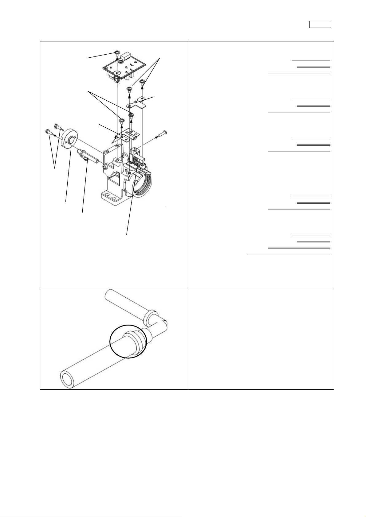
3-4-3 S socket 180U
(1) CCUK3x4SZ
(3) CCUK3x6SZ
(2) CCUK3x6SZ
RETAINING
BRAKET
180
Disassembly and Reassembly ProcedureCLV-180
(1) Take off 1 SCREW (CCUK3x4SZ) and SS BOARD
REPAIR U
Phillips bit (№2)
Torque driver
Tightening torque 0.6 Nm
(2) Take off 2 SCREWS (CCUK3x6SZ) and RETAINING
BRACKET180
Phillips bit (№2)
Torque driver
Tightening torque 0.6 Nm
HINGE 180
(6) 2 SCREWS
HEAT COVER
ATTACHMENT U
(5) PLASTIC
SCREW
SLIDEDETECTION
SPRING and SLIDE
DETECTION 180
(3) Take off 2 SCREWS (CCUK3x6SZ) and HINGE 180
Phillips bit (№2)
Torque driver
Tightening torque 0.6 Nm
(4) Take off SLIDE DETECTION SPRING and SLIDE
DETECTION 180
(5) Take off PLASTIC SCREW
Phillips bit (№2)
(6) Take off 2 SCREWS, and then take off HEAT
COVER and ATTACHMENT U
HEAT COVER POSITIONING JIG
*When putting on the HEAT COVER、tighten the
SCREW by inserting JIG into HEAT COVER
(7) Cut BINDER and pull TUBE
Tightening torque 0.2 Nm
Tightening torque 0.6 Nm
Torque driver
Phillips bit (№2)
Torque driver
4-28
ISSUE1
Page 66

3-4-4 Turret U
(3) CCUK4x6SZ
(6) CCUK3x6SZ
STOPPER
PIN
TURRET
BINDER
F FRAME
PLATE
HALOGEN LAMP
(2) CCUK4x6SZ
(1) CCUK2x4SZ
H LAMP
SHIELD
(5) CCUK2x4SZ
(4) CCUK2x4SZ
Disassembly and Reassembly ProcedureCLV-180
(1) Take off 2 SCREWS (CCUK2x4SZ) and CRAMP
BASE ECO
Phillips bit (№1)
Torque driver
Tightening torque 0.15 Nm
(2) Take off 1 SCREW (CCUK4x6SZ) and BINDER
Phillips bit (№2)
Torque driver
Tightening torque 1.4 Nm
(3) Take off 1 SCREW (CCUK4x6SZ) and TURRET
Phillips bit (№2)
Torque driver
Tightening torque 1.4 Nm
(4) Take off 2 SCREWS (CCUK2x4SZ) and F FRAME
PLATE
Phillips bit (№1)
Torque driver
Tightening torque 1.5 Nm
(5) Take off 2 SCREWS (CCUK2x4SZ) and H LAMP
SHIELD
Phillips bit (№1)
Torque driver
Tightening torque 1.5 Nm
(6) Take off 1 SCREW (CUKSK3x6SZ) and T
STOPPER PIN
Phillips bit (№2)
Torque driver
(7) Take off 3 SCREWS (CCUK3x6SZ) and H LAMP
RETAINER
Tightening torque 0.6 Nm
Phillips bit (№2)
Torque driver
Tightening torque 0.6 Nm
ISSUE1
H LAMP SPRING
(8) Take off HALOGEN LAMP and H LAMP SPRING
4-29
Page 67

Disassembly and Reassembly ProcedureCLV-180
NORMAL
] FU
NBI FU
(9) Take off NORMAL FU and NBI FU
Filter retaining jig
Torque driver
Tightening torque 0.8 Nm
(10) Take off F FRAME DUMMY
Filter retaining jig
Torque driver
Tightening torque 0.8 Nm
F FRAME
DUMMY
4-30
ISSUE1
Page 68

Chapter 5: Parts List
Parts List CLV-180
ISSUE1
5-1
Page 69

1. Exploded Parts Diagram
Parts List CLV-180
ISSUE1
5-2
Page 70

Parts List CLV-180
ISSUE1
5-3
Page 71

Parts List CLV-180
ISSUE1
5-4
Page 72
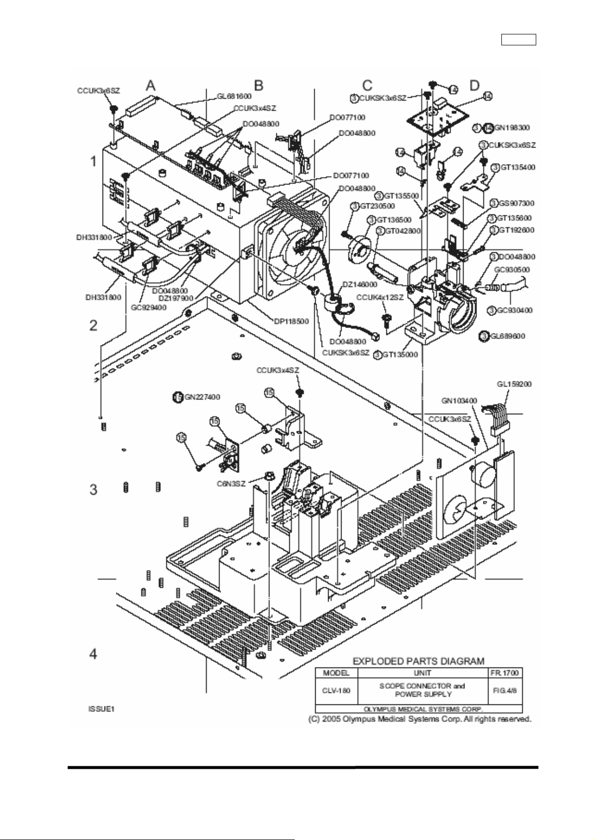
Parts List CLV-180
ISSUE1
5-5
Page 73

Parts List CLV-180
ISSUE1
5-6
Page 74

Parts List CLV-180
ISSUE1
5-7
Page 75

Parts List CLV-180
ISSUE1
5-8
Page 76

Parts List CLV-180
ISSUE1
5-9
Page 77

2. Parts List
Parts List CLV-180
ISSUE1
5-10
Page 78

Parts List CLV-180
ISSUE1
5-1 1
Page 79

Parts List CLV-180
ISSUE1
5-12
Page 80

Parts List CLV-180
ISSUE1
5-13
Page 81

OLYMPUS MEDICAL SYSTEMS CORP.
2951 Ishikawa-cho, Hachioji-shi, Tokyo Japan
Service Engineering
Service QA and Engineering Department
Production and Service Division
PRINTED IN JAPAN
ISSUE 1
 Loading...