

Olympus CK30, CK40 Instructions Manual
INSTRUCTIONS
CK30/CK40
CULTURE MICROSCOPE
This instruction manual is for the Olympus Culture Microscope Model CK30/CK40. To ensure the
safety, obtain optimum performance, and to familiarize yourself fully with the use of this microscope,
we recommend that you study this manual thoroughly before operating the microscope. Retain this
instruction manual in an easily accessible place near the work desk for future reference.
A X 7 1 6 2
i
The CK30 and CK40 Culture Microscopes have different system configurations. The differences are shown in the table below.
CK30 CK40
Observation tube
Built-in binocular tube Interchangeable*
Stage plate
– Interchangeable**
CK40-RFL reflected light
fluorescence attachment
Not mountable Mountable
* The CH3-BI45 binocular tube, CH3-TR45 trinocular tube, and CK40-TBI Tilting binocular tube are all
mountable. The CK40-EPA eyepoint adjuster can also be used, but not in combination with the CK40TBI. The only usable intermediate observation tube is the CK40-EPA. Relief phase contrast observation is not available when the CK40-EPA is used.
** In addition to the standard stage plate, you can mount the CK40-CPG glass stage plate or IX-CP50
stage plate (
50). Only 20X-or-less objectives should be used with the CK40-CPG.
SAFETY PRECAUTIONS
1. Install the microscope on a stable, horizontal table. Make sure the table is
sturdy enough to support the microscope’s weight. (Weight: CK30 –– approx.
8 kg (17.6 lb); CK40 –– approx. 8.6 kg (18.9 lb))
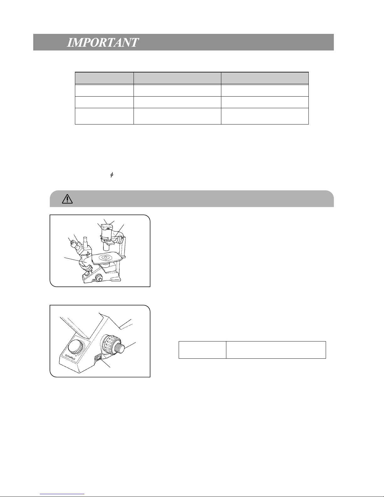
2. When transporting the microscope, always hold the lower side @ of the
observation tube and the illumination unit support ².
3. If a culture solution or water is spilled on the stage, objective or observation tube, unplug the power cord and dry it off immediately. Failure to do
so could cause equipment failure.
4. The surface of the lamp socket ³ on the lamp housing support can get
extremely hot. Make sure you leave sufficient space around the lamp
socket, especially above it, to dissipate heat. (Fig. 1)
5. To avoid potential shock hazards and burns when replacing the bulb,
make sure the main switch is set to “\” (OFF), the power cord is unplugged from the outlet, and that the lamp and the area around the lamp
socket have cooled sufficiently. (Fig. 2)
Applicable bulb Halogen bulb, 6V 30WHAL (Philips 5761)
6. Be sure to use an Olympus-specified power cord. Safety and performance
cannot be guaranteed otherwise.
7. Be sure to ground the unit. The designated electrical safety standard
cannot be guaranteed otherwise.
Fig. 1
Fig. 2
@
²
³
|
ii
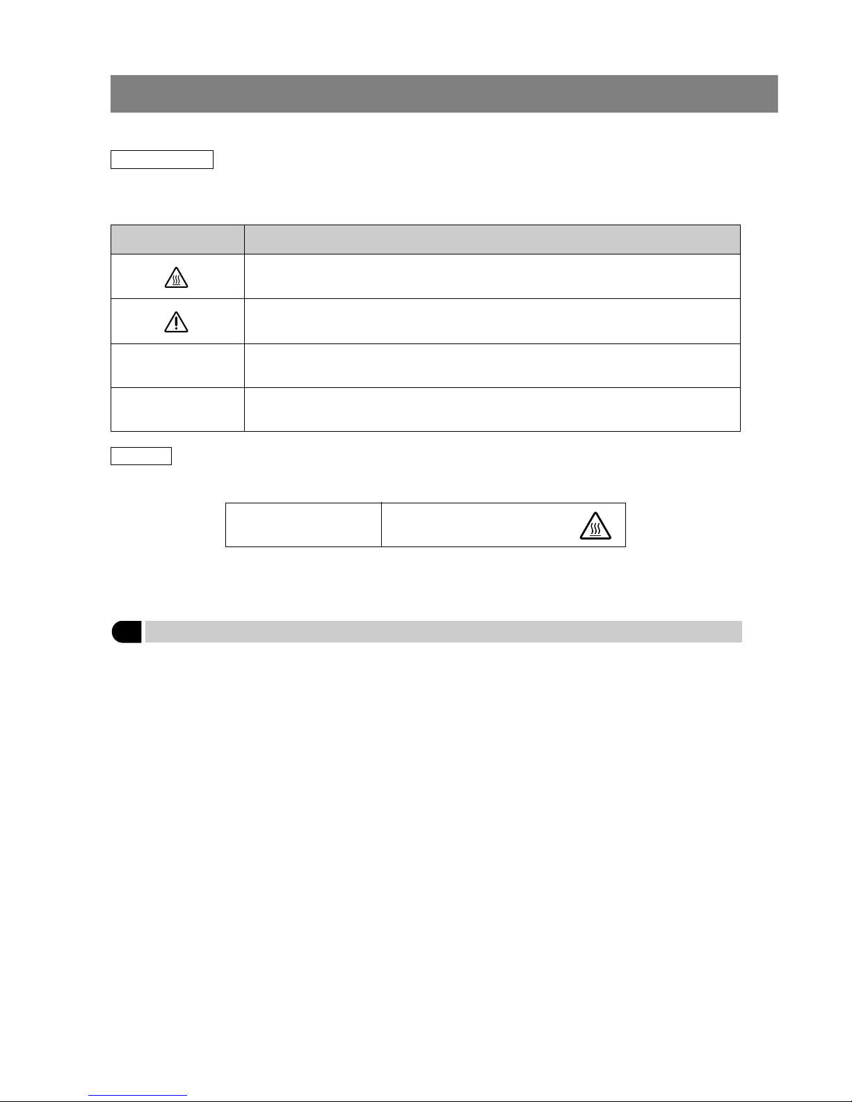
Safety Symbols
The following symbols are found on the microscope. Study the meaning of the symbols, and always use the equipment in
the safest possible manner.
Symbol Explanation
Indicates that the surface becomes hot, and should not be touched with bare hands.
Before use, carefully read the instruction manual. Improper use could result in personal injury and/or
damage to the equipment.
Indicates that the main switch is ON.
Indicates that the main switch is OFF.
l
\
Warnings
Warning indications are placed where special precautions are required when handling and using the unit.
Warning indication position
Lamp socket
[Warning against high temperature]
1 Getting Ready
1. A microscope is a precision instrument. Handle it with care and avoid subjecting it to sudden or severe impacts.
2. Do not expose the unit to direct sunlight, high temperature and humidity, dust or vibrations. (For operating conditions, refer
to “8. Specifications” on page 26.)
3. Use the tension adjustment ring to adjust the tension of the coarse adjustment knob.
4. Use a flat-head screwdriver to set the voltage selector on the rear panel of the microscope body to the required voltage.
}The selector is factory preset to the high-voltage side (110 – 120 V or 230 – 240 V).

iii
2 Maintenance and Storage
1. Clean all glass components by wiping gently with gauze. To remove fingerprints or oil smudges, wipe with gauze slightly
moistened with a mixture of ether (70%) and alcohol (30%).
# Do not use a mixture of ether (70%) and alcohol (30%) to clean the lower lens (made of optical plastic) of the
eyepiece (NCWHK10X) because such solvents cloud the lens. If dust adheres to the lens, blow it off or wipe it away
gently with a dry cloth.
Since solvents such as ether and alcohol are highly flammable, they must be handled carefully. Be sure to keep
these chemicals away from open flames or potential sources of electrical sparks —— for example, electrical
equipment that is being switched on or off. Also remember to always use these chemicals only in a wellventilated room.
2. Many parts of the exterior are made of plastic. Wipe the unit with a clean cloth only. Do not use organic solvents to clean
non-optical components. If smudges are difficult to remove, wipe them with a soft cloth slightly moistened with a diluted
neutral detergent.
3. Be careful not to spill any liquid –– such as a culture solution –– on the unit. If you do spill anything, immediately set the
main switch to “ ” (OFF) and unplug the power cord. Then wipe away any liquid on the objectives or under the objectives.
4. If no objectives are mounted, be sure to cover the objective mounting threaded holes on the revolving nosepiece to
prevent dust and spilled culture solution from getting on the lenses inside.
5. Never disassemble any part of the unit. Doing so could cause malfunctions or reduced performance.
6. When the unit is not in use, keep it covered with a dust cover. Make sure the lamp socket is cool before covering the unit.
7. Using a device that radiates ultraviolet light such as a germicidal lamp near the unit may discolor (yellow) parts of the
unit´s surface. The amount of discoloration depends on the radiation intensity of the ultraviolet light and the distance
between the unit and radiation source. When not using the unit, cover it with the dust cover. We recommend that you also
cover the unit with an impermeable sheet.
3 Caution
If the equipment is used in a manner not specified by this manual, the safety of the user may be imperiled. In addition, the
equipment may also be damaged. Always use the equipment as outlined in this instruction manual.
The following symbols are used to set off text in this instruction manual.
: Indicates that failure to follow the instructions in the warning could result in bodily harm to the
user and/or damage to equipment (including objects in the vicinity of the equipment).
# : Indicates that failure to follow the instructions could result in damage to equipment.
} : Indicates commentary (for ease of operation and maintenance).

CK30/CK40
1 NOMENCLATURE
2 ASSEMBLY
3 CONTROLS
4 SUMMARY OF OBSERVATION PROCEDURES
5 USING THE CONTROLS
6 PHASE CONTRAST OBSERVATION
7 PHOTOMICROGRAPHY
8 SPECIFICATIONS
9 TROUBLESHOOTING GUIDE
PROPER SELECTION OF THE POWER SUPPLY CORD ............................................................................. 30
1
3
9
11
12
19
23
25
27
2-1 Assembly Diagram ................................................................................................................................................................... 3
2-2 Detailed Assembly Procedure ................................................................................................................................. 4
5-1 Microscope Body...................................................................................................................................................................... 12
5-2 Stage ........................................................................................................................................................................................................... 13
5-3 Observation Tube ..................................................................................................................................................................... 14
5-4 Illumination Unit .......................................................................................................................................................................... 17
5-5 Objectives............................................................................................................................................................................................ 18
1
1
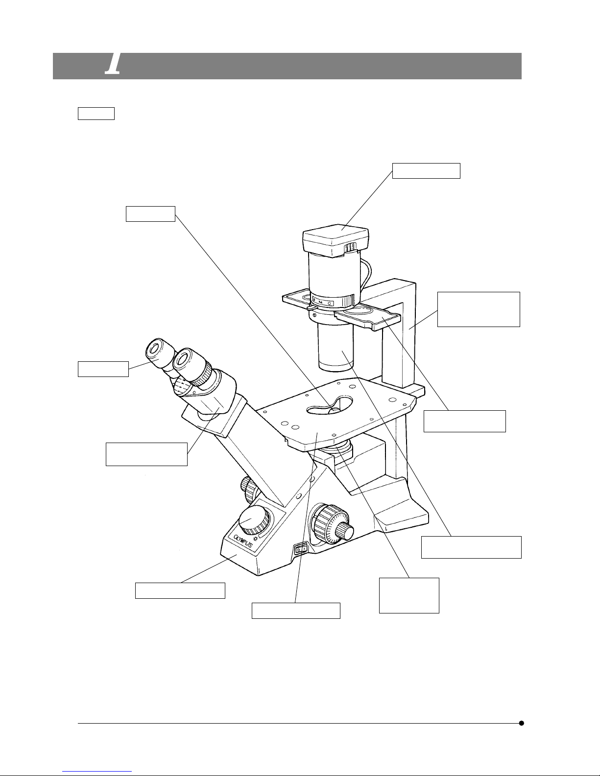
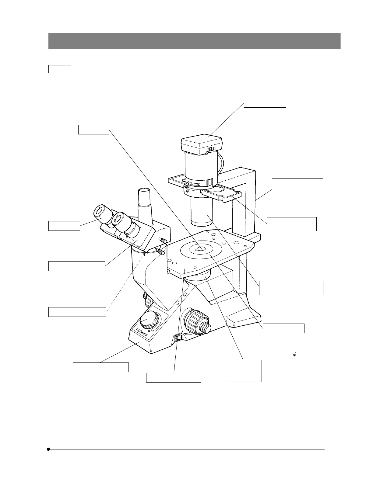
NOMENCLATURE
CK30
Objective
For observation:
EDAch4X
EDAch10X
LWDCDAch20X
# A dedicated objective is
required for ordinary
phase contrast observation and relief phase
contrast observation.
(See page 19.)
Eyepiece
· NCWHK10X
· WHK10X
· WHK15X
Binocular tube
(stationary)
Microscope body
CK30-F
Stage (stationary)
· Stage extension plate:
CK2-SS
· Mechanical stage:
CK40-MVR
Revolving
nosepiece
(stationary)
Quadruple
revolving nosepiece
Ultra-long working
distance condenser
Phase contrast
slider
· Pre-centered Ph slider:
CK40-SLP
· Centering Ph slider:
CK40-SL
· RP slider:
CK40-RPSL
Illumination unit
support
(stationary)
Lamp socket
U-LS30-3
CK30/CK40
2
CK40
Objective
For observation:
EDAch4X
EDAch10X
LWDCDAch20X
# A dedicated objective is
required for ordinary
phase contrast observation and relief phase
contrast observation.
Eyepiece
· NCWHK10X
· WHK10X
· WHK15X
Microscope body
CK40-F
Stage (stationary)
· Stage extension plate:
CK2-SS
· Mechanical stage:
CK40-MVR
Revolving
nosepiece
(stationary)
Quadruple
revolving nosepiece
Phase contrast
slider
· Ph precentering slider:
CK40-SLP
· Ph centering slider:
CK40-SL
· RP slider:
CK40-RPSL *
Illumination unit
support
(stationary)
Lamp socket
U-LS30-3
Observation tube
· Binocular tube: CH3-BI45
· Trinocular tube: CH3-TR45
· Tilting binocular tube:
CK40-TBI
Eyepoint adjuster
· CK40-EPA
# Cannot be combined with
the CK40-TBI.
Stage plate
· Standard stage plate
· Glass stage plate:
CK40-CPG
· Stage plate ( 50):
IX-CP50
Ultra-long working
distance condenser
* Relief phase contrast observation is not possible with the CK40-EPA.
3
ASSEMBLY
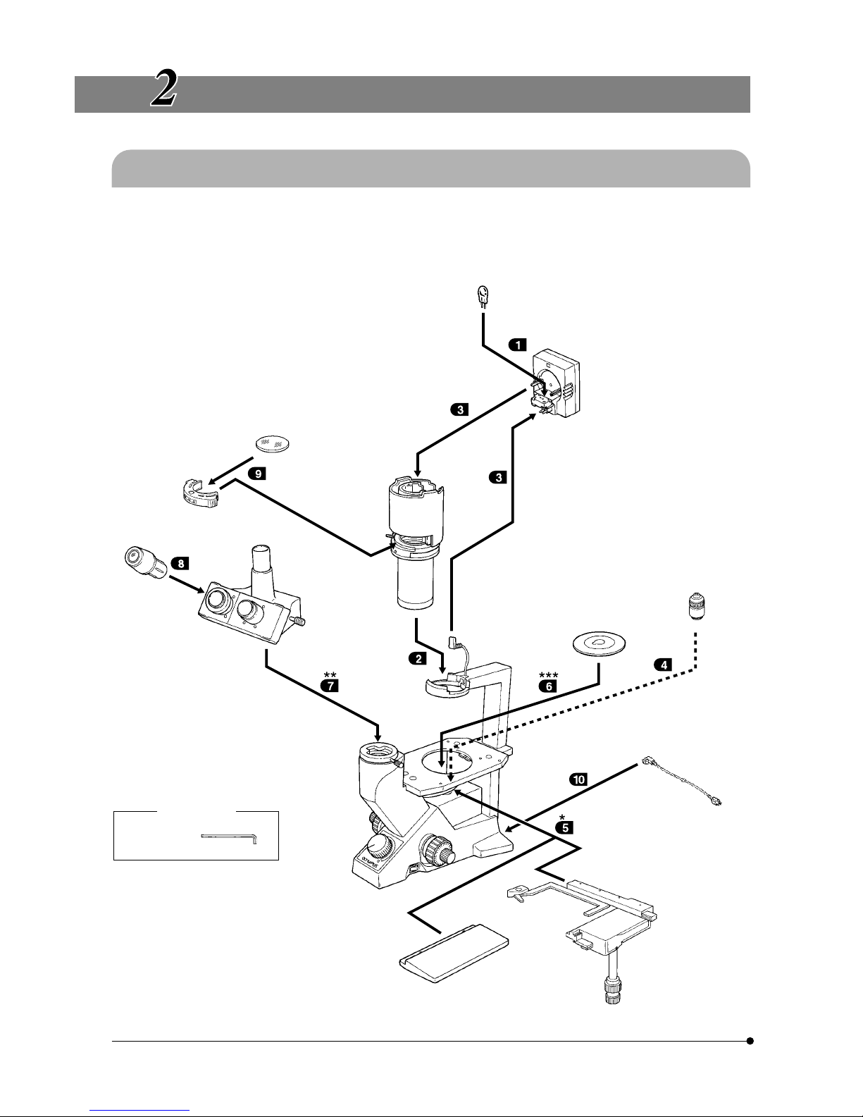
2-1 Assembly Diagram
The diagram below shows the assembly sequence for the various modules. The numbers indicate the order of assembly.
# When assembling the equipment, make sure that all parts are free of dust and dirt. Avoid scratching any parts or glass
surfaces.
# Keep the provided Allen wrench on hand. You will need it when replacing the modules.
Allen wrench
Required tool
* Can also be mounted on the
left side. However, the mechanical stage cannot be mounted
in the same position as the
stage extension plate.
** The CK30 is provided with sta-
tionary binocular tube.
Halogen bulb
6V 30W HAL
Lamp socket
U-LS30-3
Filter
Filter holder
Transmitted
illumination
unit
Stage plate
· Standard stage plate
· CK40-CPG
· IX-CP50
Objective
Eyepiece
· NCWHK10X
· WHK10X
· WHK15X
Observation tube
· CH3-BI45
· CH3-TR45
· CK40-TBI
Power cord
Microscope body
· CK30-F
· CK40-F
Stage extension plate
CK2-SS
Mechanical stage
CK40-MVR
***The CK30 is not provided with
a stage plate.
CK30/CK40
4
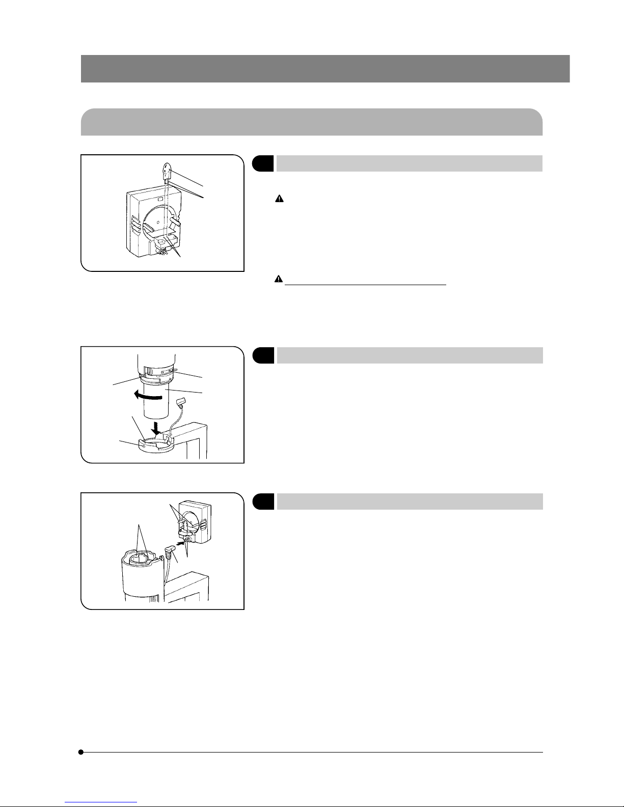
2-2 Detailed Assembly Procedure
1 Mounting and Replacing the Bulb
(Fig. 3)
}Use only the specified Philips 5761 halogen bulb, 6 V 30 W HAL.
To prevent reduced bulb life or cracking, do not touch the bulb with
bare hands. If fingerprints are accidentally left on the bulb, wipe the
bulb with a soft cloth.
1. Hold the bulb @ with gauze or other protective material and insert the
bulb pins ² into the lamp socket’s pin holes ³ as far as they will go.
# Insert the bulb gently. Squeezing too hard will damage the bulb.
Bulb replacement during use or after use:
The bulb and the lamp socket surfaces and vicinity will be extremely
hot during use and right after use. Set the main switch to “ \ ” (OFF)
and disconnect the power cord from the wall outlet. Then allow the
old bulb, lamp housing and vicinity to cool before replacing the bulb.
2 Installing the Transmitted Illumination Unit
(Fig. 4)
1. While aligning the indicator groove ² on the transmitted illumination unit
@ with the notch ³ on the lamp housing support´s brace, insert the
illumination unit @ gently into the support’s brace.
2. Turn the illumination unit @ 90° clockwise so that “ AS ” on the filter
holder faces directly to the front. Then tighten the clamping screw ƒ
using the Allen wrench provided with the microscope body to fix it securely.
3 Installing the Lamp Socket
(Fig. 5)
1. Connect the plug @ with the socket pin ². Then, while aligning the
guide pins ³ with the condenser’s guide holes |, push the lamp socket
gently onto the Illumination unit.
Fig. 3
Fig. 4
Fig. 5
@
²
³
@
²
³
|
ƒ
@
²
³
|
5
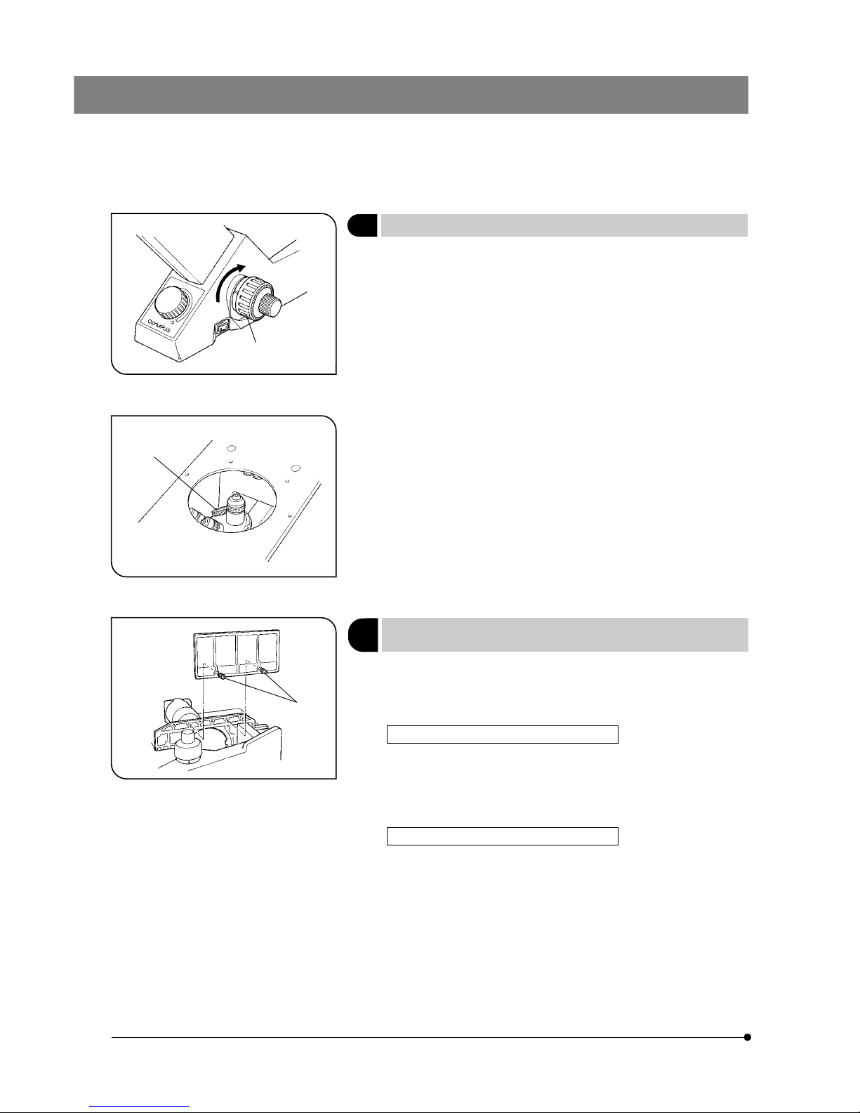
4 Mounting the Objectives
(Fig. 6 & 7)
#First raise the revolving nosepiece slightly to remove the transporta-
tion pad on the nosepiece’s base.
}Keep the transportation pad in a safe place. You will need it when the
equipment is sent for repair or transported to another location.
1. Turn the coarse adjustment knob @ towards the back until the revolving
nosepiece is set at its lower limit. (Fig. 6)
2. Screw the objective with the lowest magnification into the revolving nosepiece from the left side. Then turn the nosepiece clockwise and mount
the remaining objectives in order of magnification –– from low to high.
}Mounting the objectives this way makes it easier to change magnifica-
tion.
}With the CK40, the objectives can be mounted through the opening on
the stage.
#Clean the objectives periodically. The objective tips on a culture
microscope are susceptible to dust.
#Be sure to cover any unused threaded holes with the objective cap
² to prevent dirt and dust from getting inside. (Fig. 7)
5
Mounting the Stage Extension
Plate/Mechanical Stage
(Fig. 8)
}The stage extension plate can be mounted on the left or right side of the
stage to expand the stage surface. However, the stage extension plate
and mechanical plate cannot be used simultaneously on the same side.
Mounting the CK2-SS Stage Extension Plate
Screw the clamping screws @ into the stage extension plate and then
into the plain stage from above on the right side or from below on the left
side. Tighten them with a coin or similar tool until the plate is securely
attached.
Mounting the CK40-MVR Mechanical Stage
}This can also be mounted on either the left or right side of the stage.
Mount it in the same way as the stage extension plate.
Fig. 6
Fig. 7
Fig. 8
@
²
@
CK30/CK40
6
6
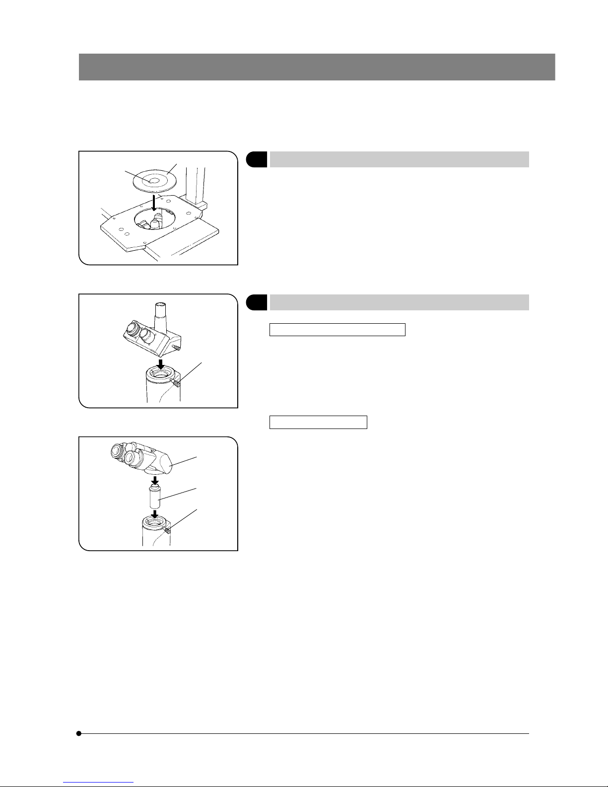
Mounting the Stage Plate (CK40 Only)
(Fig. 9)
Fit the standard stage plate @ into the opening on the stage.
#Turn the standard stage plate so that the notch ² faces to the
front for easy confirmation of an objective tip. When using the
glass stage plate, set it in the direction so that its product code
inscription “ CK40-CPG ” can be read from the front.
7
Mounting the Observation Tube (CK40 Only)
(Fig. 10 & 11)
Mounting the CH3-BI45/CH3-TR45
1. Loosen the observation tube clamping knob @. (Fig. 10)
2. Insert the circular dovetail at the bottom of the observation tube into the
mount opening on the microscope body. Adjust the observation tube
until the binocular eyepieces face directly to the front, and then tighten
the clamping thumbscrew. (Fig. 10)
Mounting the CK40-TBI
1. Loosen the observation tube clamping knob @ as much as possible
without it coming off. (Fig. 11)
2. Carefully insert the relay lens tube ³ of the CK40-TBI ² into the observation tube mount opening. (Fig. 11)
3. Insert the circular dovetail at the bottom of the CK40-TBI ² into the mount
opening on the microscope body. Adjust the observation tube until the
binocular eyepieces face directly to the front, and then tighten the clamping knob. (Fig. 11)
# Do not mount the observation tube on the microscope body at an
extremely oblique angle. If you do, the observation tube’s dovetail
could hit the relay lens tube and damage it.
# Use in combination the CK40-TBI ² and relay lens tube ³ from the
same package.
Fig. 9
Fig. 10
Fig. 11
@
²
@
@
²
³
7
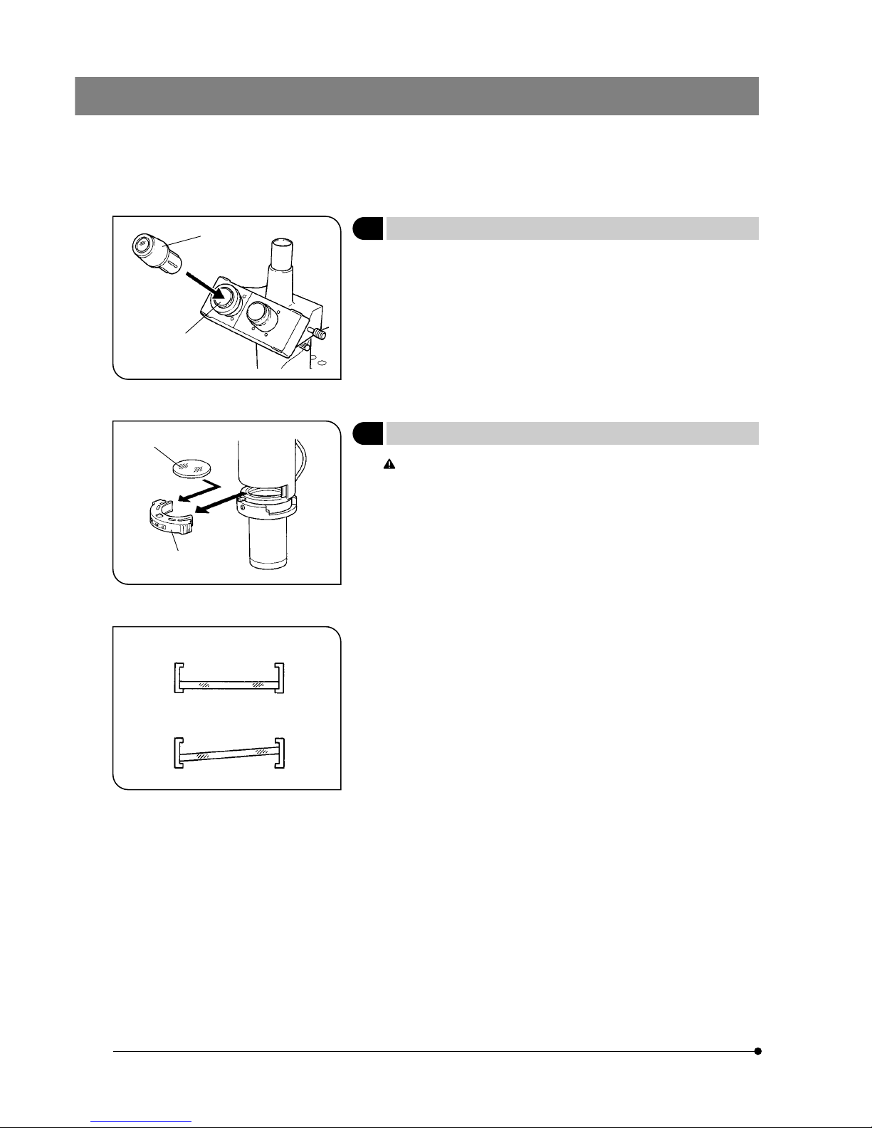
8 Mounting the Eyepieces
(Fig. 12)
Insert the eyepiece @ into the eyepiece sleeve ² on the observation
tube.
9 Mounting the Filter
(Fig. 13 & 14)
Let the filter cool down sufficiently before replacing the filter.
Remove the filter holder @ and mount the required filter ².
#Push the filter down to the bottom as shown in Fig. 14 so that it does
not tilt. If the filter is inclined or is not pushed down to the bottom, it
may fall off the filter mount.
}Filters can be stacked in the filter holder. You can mount as many as you
like, as long as the total thickness does not exceed 11 mm.
Fig. 12
Fig. 13
Fig. 14
@
@
²
Incorrect
Correct
²
 Loading...