

Page 1
Safety Check Instruction
SCI.991007-1.4
Product name:
Hardware version:
CelonLab ENT (100...120 V~)
30
REF no.:
WB991007
LAB991.025.007
The unit must undergo a safety check at annual intervals in accordance with the national statutory regulations. Please follow these test
instructions. All tests must be done with fully functional and calibrated test equipment and by technicians trained in the service / maintenance
of electrical medical devices. Record the test results in the “safety check report” for reference in future tests and provide the user of the unit
with a signed report. If the unit fails to meet any of the checks, contact the manufacturer.
During service / maintenance take care of the different hardware versions which may be applicable (see below).
The hardware version of the unit can be identified by the serial number which can be found on the type plate at the back side of the unit. The
table below shows the serial number range to identify the hardware version.
Hardware version
Serial number (SN)
30 … 31
A22701LE01.0001 ... A58702LE01.9999
32 … ≥ 35
1000-1001 … 6172-9999
From hardware version 35 the serial number itself includes already the hardware version. This code was introduced for units manufactured
since February 2005.
Example: 1234W35-567
Recommended test equipment and accessories
Electrical safety tester (Example: Unimet 1000 ST, Bender)
Electrosurgical analyzer (Example: QA-ES, Metron)
Load resistor 100 Ω, 25 W (or more), 5 % tolerance, low inductive part, short time load
Connection cables, HF-output (banana) to electrosurgical analyzer or load resistor
Power cord
Footswitch
Hardware version
© Celon AG Page 1 / 9
, Issue date: 01.09.2008
Page 2
Safety Check Instruction
SCI.991007-1.4
1. Inspection of the unit and the accessories
No.
Procedure
010
Accompanying documents are present and legible:
- Instructions for Use
- EMC-Guidelines
- final test report (incl. test protocols according to the final test report)
- optional (depending on the country): medical device information (“Medizinproduktebuch”)
020
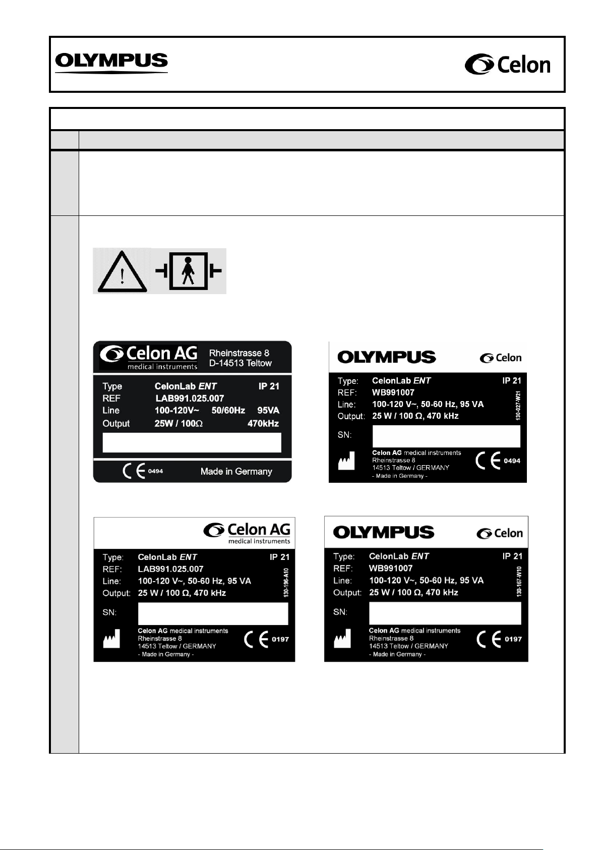
Labels present and legible:
Sample of symbol: “Unit is defibrillator-safe”
Visible on the front panel (see fig. 2)
Sample of symbol: “Caution! Read the Instructions for Use!”
Visible on the front panel (see fig. 2)
Samples of type plates: Details of the manufacturer, supply voltage, supply frequency, moisture
protection class (IP), reference number, serial number (e.g. 1234W34-567), power input, power
output, and output frequency.
Visible on the back of the unit (see fig. 1)
SN: 3580-1001
3580A34-567
1234W34-567
1234W34-567
© Celon AG Page 2 / 9
, Issue date: 01.09.2008
Page 3
Safety Check Instruction
SCI.991007-1.4
No.
Procedure
020
030
Unit and accessories are externally undamaged:
- Enclosure and front panel have no serious destructions
040
Lift up the unit and shake it gentle. No clatter noise should be audible.
Documentation
050
Document the test results in “SCR.991007.
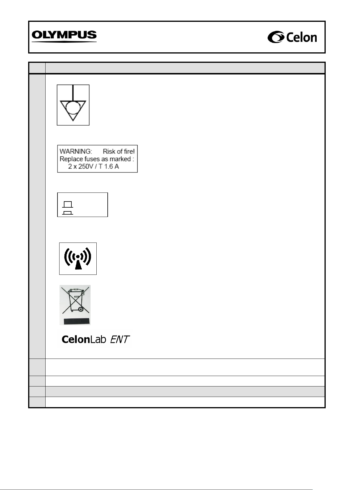
Sample of symbol: Connection for equipotential bonding
Visible on the back of the unit (see fig. 1)
Samples of label for power fuses:
Visible on the back of the unit (see fig. 1)
Sample of symbol: “Non-ionizing radiation”
Visible on the back of the unit (see fig. 1)
Sample of label for volume switch:
Visible on the back of the unit (see fig. 1)
Sample of label: Product name
Visible on the front panel (see fig. 2)
SPEAKER VOLUME
HIGH
LOW
Sample of symbol: “Waste electrical and electronic equipment”
Visible on the back of the unit, only applicable for
units within the European Union and sold after
August 13th, 2005. (see fig. 1)
© Celon AG Page 3 / 9
, Issue date: 01.09.2008
Page 4

Safety Check Instruction
SCI.991007-1.4
Fig. 1: Sample of the backside of the CelonLab ENT power control unit
Fig. 2: Sample of the front panel of the CelonLab ENT power control unit
© Celon AG Page 4 / 9
, Issue date: 01.09.2008
Page 5

Safety Check Instruction
SCI.991007-1.4
2. Display function check
No.
Procedure
Test accessories: Power cord
060
Connect the unit via power cord with a rated supply voltage. Switch on the unit and wait several seconds
until the power level display shows “1”.
070
Press the “UP“-button of the power setting (increasing the power) ten times.
The power level display has to be increased by 1 per step until “10” (starting from “1”) is shown.
080
Press the “UP“-button of the power setting (increasing the power) and hold it down.
The power level display has to be increased step-by-step until “25” is shown.
090
Press the “DOWN“-button of the power setting (reducing the power) ten times.
The power level display has to be reduced by 1 per step until “15” (starting from “25”) is shown.
100
Press the “DOWN“-button of the power setting (reducing the power) and hold it down.
The power level display has to be reduced step-by-step until “1” is shown.
Documentation
110
Document the test results in “SCR.991007”.
3. Power output
No.
Procedure
Test equipment: Electrosurgical analyzer (Example: QA-ES, Metron)
Connection cables, HF-output (banana) to the electrosurgical analyzer
Test accessories: Power cord
Footswitch
120
Connect the unit via the power cord with a rated supply voltage. Connect the footswitch with the unit.
130
Connect the unit via the connection cables at the HF-output 1 and 2 (see fig. 3) with the electrosurgical
analyzer according to the analyzer’s instructions for use and measure the following parameter:
Attention: Start measuring after the display shows the appropriate value and make sure to
release the footswitch before starting with a new measurement.
140
The power output at 5 (output load 100 Ω) has to be in the range of 4 W P 6 W.
150
The power output at 10 (output load 100 Ω) has to be in the range of 8 W P 12 W.
160
The power output at 15 (output load 100 Ω) has to be in the range of 12 W P 18 W.
170
The power output at 20 (output load 100 Ω) has to be in the range of 16 W P 24 W.
180
The power output at 25 (output load 100 Ω) has to be in the range of 20 W P 30 W.
Documentation
190
Document the test results in “SCR.991007”.
© Celon AG Page 5 / 9
, Issue date: 01.09.2008
Page 6

Safety Check Instruction
SCI.991007-1.4
4. Valid resistance range
No.
Procedure
Test equipment: Electrosurgical analyzer (Example: QA-ES, Metron)
Connection cables, HF-output (banana) to the electrosurgical analyzer
Test accessories: Power cord
Footswitch
200
Connect the unit via the power cord with a rated supply voltage. Connect the footswitch with the unit.
210
Connect the unit via the connection cables at the HF-output 1 and 2 (see fig. 3) with the electrosurgical
analyzer according to the analyzer’s instructions for use. Set the power level of the unit to “12” and
measure the following parameter:
Attention: Start check procedure, if not already done, after setting the power level to “12”and
make sure to release the footswitch before starting with a new check procedure.
Short circuit detection
220
The following signals and warnings have to occur at an output load of 10 Ω (unit shut off):
- The blue LED (signal lamp “power output”) is dark.
- The red LED (signal lamp “resistance too low”) is blinking.
- An alarm signal (pulsed tone) is audible.
230
The following signals have to occur with a load resistor of 25 Ω (normal function of the unit):
- The blue LED (signal lamp “power output”) glows.
- The red LED (signal lamp “resistance too low”) is dark.
- A continuous signal is audible.
HF-output 1
HF-output 2
Fig. 3: Sample of the front panel of the power control unit showing the HF-outputs.
© Celon AG Page 6 / 9
, Issue date: 01.09.2008
Page 7

Safety Check Instruction
SCI.991007-1.4
No.
Procedure
Upper shut off limit
240
The following signals have to occur with a load resistor of 325 Ω (normal function of the unit):
- The blue LED (signal lamp “power output”) glows.
- The red LED (signal lamp “resistance too low”) is dark.
- A high frequency continuous signal is audible.
250
The following signals have to occur with a load resistor of 450 Ω (unit does not shut off):
- The blue LED (signal lamp “power output”) glows.
- The red LED (signal lamp “resistance too low”) is dark.
- A pulsed signal with a high audio frequency is audible (end of treatment).
Documentation
260
Document the test results in “SCR.991007”.
5. High frequency leakage current (according to IEC 60601-2-2)
No.
Procedure
Test equipment: Electrosurgical analyzer (Example: QA-ES, Metron)
Load resistor 100 Ω, 25 W (or more), 5 % tolerance, low inductive part, short time
load
Connection cables, HF-output (banana) to the electrosurgical analyzer and the load
resistor
Test accessories: Power cord
Footswitch
270
Measurement of the high frequency leakage current according to 19.3.101 a) 3) (bipolar application) as
described in IEC 60601-2-2. The output being loaded and unloaded at rated load.
Connect the unit via the power cord with a rated supply voltage. Connect the footswitch with the unit.
280
Connect the load resistor (100 Ω) with the HF-output 1 and 2 and with the electrosurgical analyzer
according to the analyzer’s instructions for use to measure high frequency leakage currents. Set the
power level of the unit to “25” and measure the following parameter:
Attention: Start measuring, if not already done, after setting the power level to “25”and make
sure to release the footswitch before starting with a new measurement.
290
High frequency leakage current of HF-output 1 at output load 100 Ω: ≤ 35.4 mA.
300
High frequency leakage current of HF-output 2 at output load 100 Ω: ≤ 35.4 mA.
310
Disconnect the load resistor (100 Ω) from the HF-output 1 and 2.
320
Connect the HF-output 1 and 2 with the electrosurgical analyzer according to the analyzer’s instructions
for use to measure high frequency leakage currents. Set the power level of the unit to “25” and measure
the following parameter:
Attention: Start measuring, if not already done, after setting the power level to “25”and make
sure to release the footswitch before starting with a new measurement.
330
High frequency leakage current of HF-output 1 with open output: ≤ 35.4 mA.
340
High frequency leakage current of HF-output 2 with open output: ≤ 35.4 mA.
Documentation
350
Document the test results in “SCR.991007”.
© Celon AG Page 7 / 9
, Issue date: 01.09.2008
Page 8

Safety Check Instruction
SCI.991007-1.4
6. Earth resistance (according to IEC 60601-1 and IEC 62353)
No.
Procedure
Test equipment: Electrical safety tester (Example: Unimet 1000 ST, Bender)
Test probe
Test accessories: Power cord
Footswitch
360
Connect the unit with an electrical safety tester according to the tester’s instructions for use and measure
the following parameters against metal parts which can be touched:
370
Protective earth resistance: ≤ 0.3 Ω
Documentation
380
Document the test results in “SCR.991007”.
7. Current and power consumption
No.
Procedure
Test equipment: Electrical safety tester (Example: Unimet 1000 ST, Bender)
Load resistor 100 Ω, 25 W (or more), 5 % tolerance, low inductive part, short time
load
Connection cables, HF-output (banana) to the load resistor
Test accessories: Power cord
Footswitch
390
Connect the unit with an electrical safety tester according to the tester’s instructions for use. Connect
HF-output 1 and 2 of the unit (see fig. 3) via the connection cables with the 100 Ω load resistor. Set the
power level of the unit to “25” and press the footswitch to measure the following parameters:
Attention: Start measuring, if not already done, after setting the power level to “25”and make
sure to release the footswitch before starting with a new measurement.
400
Current consumption under load at 100...120 V~: IL 1.0 A
410
Power consumption under load at 100...120 V~: SL 110 VA
Documentation
420
Document the test results in “SCR.991007”.
© Celon AG Page 8 / 9
, Issue date: 01.09.2008
Page 9

Safety Check Instruction
SCI.991007-1.4
8. Inspection label
No.
Procedure
430
Cover or exchange an inspection label (as shown below) at the enclosure back of the unit and mark the
due date of the next periodic safety check (month/year). The unit must undergo a safety check at annual
intervals.
Documentation
440
Document the test results in “SCR.991007”.
© Celon AG Page 9 / 9
, Issue date: 01.09.2008
 Loading...