

Page 1

C. ADJUSTMENT METHOD C-40ZOOM/D-40ZOOM
C. ADJUSTMENT METHOD
[1] TABLE FOR SERVICING TOOLS ........................................................................... C-2
[2] EQUIPMENT ........................................................................................................... C-2
[3] ADJUSTMENT ITEMS AND ORDER.......................................................................C-2
[4] SETUP ....................................................................................................................C-2
[5] CONNECTING THE CAMERA TO THE COMPUTER ............................................. C-3
[6] USB STORANGE INFORMATION REGISTRATION ...............................................C-4
[7] ADJUST SPECIFICATIONS .................................................................................... C-4
1. LENS ADJUSTMENT .........................................................................................C-4
2. AWB ADJUSTMENT ..........................................................................................C-5
3. COLOR ADJUSTMENT .....................................................................................C-5
4. CCD WHITE POINT DEFECT DETECT ADJUSTMENT ...................................C-5
5. CCD BLACK POINT DEFECT DETECT ADJUSTMENT .................................. C-5
6. LCD PANEL ADJUSTMENT .............................................................................. C-6
6-1. LCD H AFC ADJUSTMENT .......................................................................C-6
6-2. LCD RGB OFFSET ADJUSTMENT ........................................................... C-6
6-3. LCD GAIN ADJUSTMENT ......................................................................... C-6
6-4. LCD RED BRIGHTNESS ADJUSTMENT.................................................. C-6
6-5. LCD BLUE BRIGHTNESS ADJUSTMENT ............................................... C-7
[8] ADJUSTMENT ITEMS ............................................................................................C-8
SIMENS STAR CHART ................................................................................................... C-9
C-1 Ver.1
Page 2
C. ADJUSTMENT METHOD C-40ZOOM/D-40ZOOM
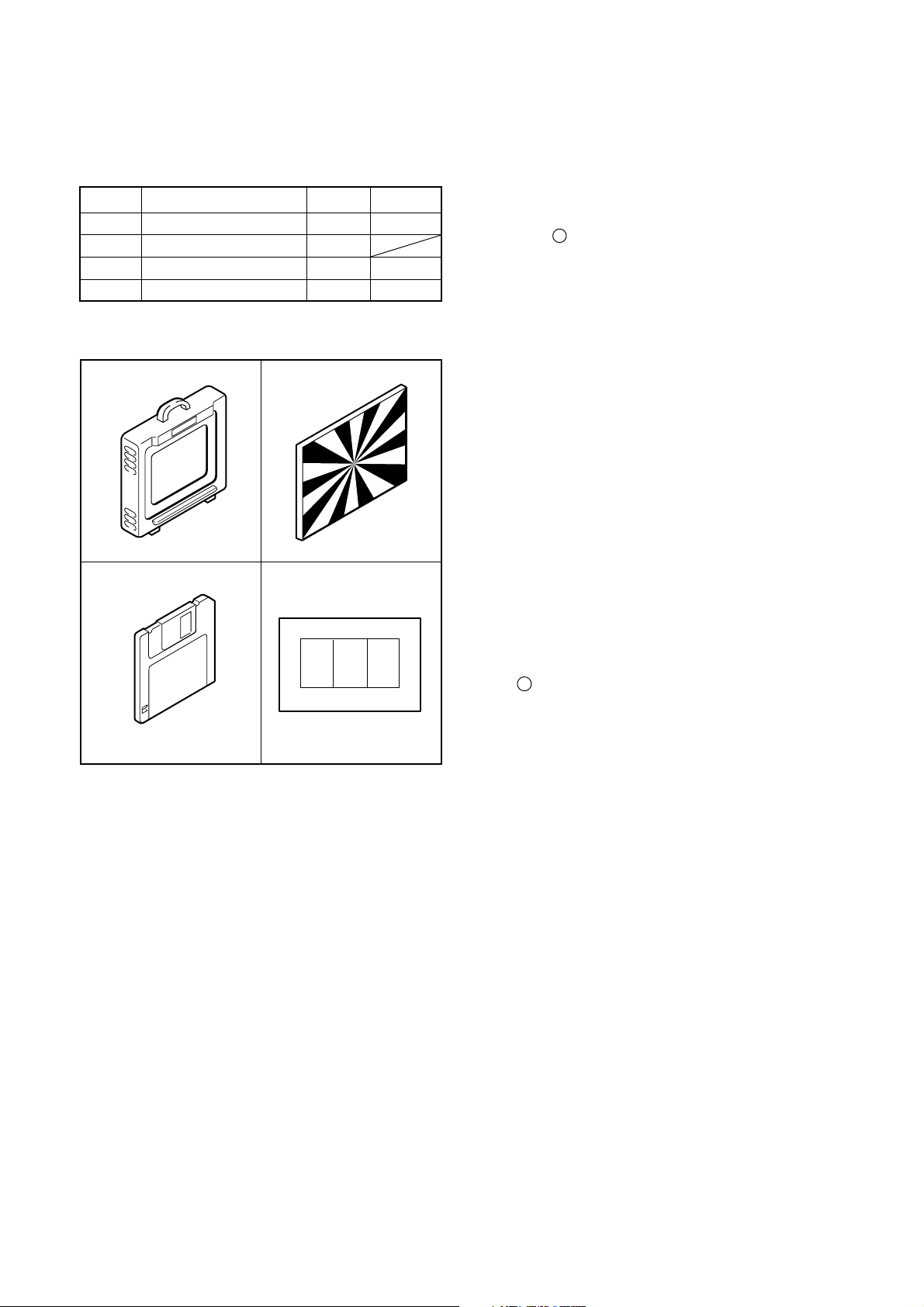
[1] Table for Servicing Tools
Ref. No.
J-1
J-2
J-3
J-4
Note: J-1 color viewer is 100 - 110 VAC only.
Color viewer
Siemens star chart
Calibration software
Chart for color adjustment
Name Part code
Number
1
1
1
1
J-1 J-2
J-3
J-4
VJ8-0007
VJ8-0184
VJ8-0155
[2] Equipment
1. Oscilloscope
2. Digital voltmeter
3. AC adaptor
4. PC (IBM R -compatible PC, Pentium processor, Window
98 or Me)
[3] Adjustment Items and Order
1. Lens Adjustment
2. AWB Adjustment
3. Color Adjustment
4. CCD White Point Defect Detect Adjustment
5. CCD Black Point Defect Detect Adjustment
6. LCD Panel Adjustment
6-1. LCD H AFC Adjustment
6-2. LCD RGB Offset Adjustment
6-3. LCD Gain Adjustment
6-4. LCD Red Brightness Adjustment
6-5. LCD Blue Brightness Adjustment
Note:
1. If the lens, CCD, board and changing the part in item 1-
5 replace, it is necessary to adjust again. Item 2-4 adjustments should be carried out in sequence. Item 5 adjustments should be carried out after item 2.
[4] Setup
1. System requirements
Windows 98 or Me
IBM R -compatible PC with pentium processor
CD-ROM drive
3.5-inch high-density diskette drive
USB port
40 MB RAM
Hard disk drive with at least 15 MB available
VGA or SVGA monitor with at least 256-color display
2. Installing calibration software
1. Insert the calibration software installation diskette into
your diskette drive.
2. Open Explorer.
3. Copy the DSC Cal folder on the floppy disk in the FD
drive to a folder on the hard disk.
3. Installing USB drive
Install the USB drive with camera or connection kit for PC.
C-2 Ver. 1
Page 3
C. ADJUSTMENT METHODC-40ZOOM/D-40ZOOM
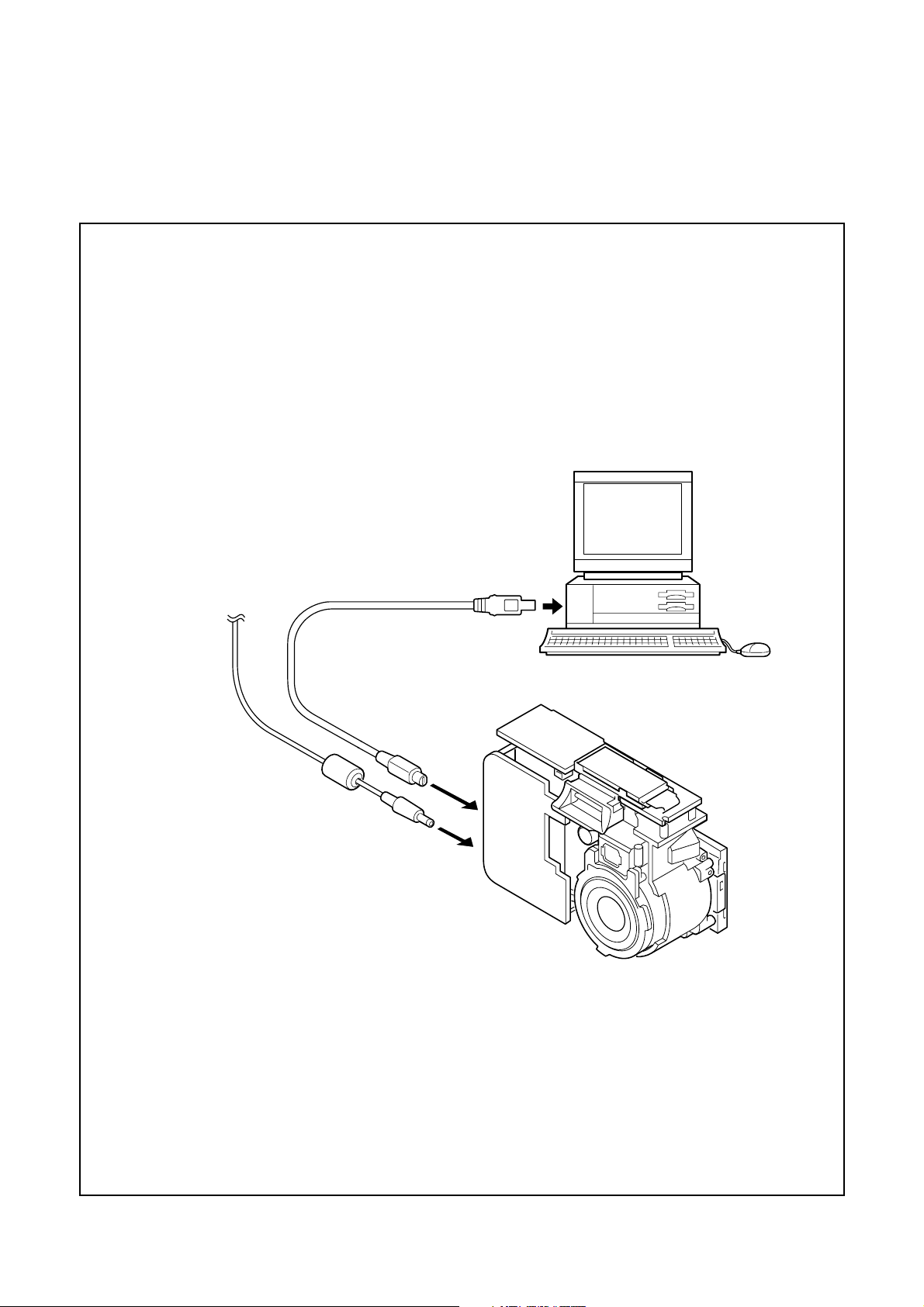
[5] Connecting the camera to the computer
1. Line up the arrow on the cable connector with the notch on the camera's USB port. Insert the connector.
2. Locate a USB port on your computer.
AC adaptor
To USB port
USB cable
Ver. 1
C-3
Page 4

C. ADJUSTMENT METHOD C-40ZOOM/D-40ZOOM
[6] USB Storage Information Registration
USB storage data is important for when the camera is connected to a computer via a USB connection.
If there are any errors in the USB storage data, or if it has
not been saved, the USB specification conditions will not be
satisfied, so always check and save the USB storage data.
Preparation:
POWER switch: ON
Adjustment method:
1. Connect the camera to a computer. (Refer to [5] Con necting the camera to the computer on the page C-3.)
2. Double-click on the DscCalDi128.
3. Click on the Get button in the USB storage window and
check the USB storage data.
VID: OLYMPUS
PID: C-40Z/D-40Z
Serial:
Rev. : 1.00
4. Check the “Serial” in the above USB storage data. If the
displayed value is different from the serial number
printed on the base of the camera, enter the number on
the base of the camera. Then click the Set button.
5. Next, check VID, PID and Rev. entries in the USB stor age data. If any of them are different from the values in
3. above, make the changes and then click the corre sponding Set button.
Calibration
AWB
Focus
UV Matrix
Cal Mode
Cal Data
USB strage
VID
Get
PID
Set
OK
OK
Upload
Firmware
Image
Initialize
EVF
LCD Type
LCD
R Bright
RGB Offset
Tint
H AFC Test
Serial
Set
Set
Rev.
B Bright
Gain
Phase
Set
Set
VCOMDC
VCOMPP
Setting
Language
Video Mode
[7] Adjust Specifications
1. Lens Adjustment
Camera
Approx.
150 cm 3cm
Siemens
star chart
Setting the adjustment mode
1. Open the card cover of the camera.
2. Push the OK/menu button and monitor button more than
3seconds simultaneously. Display “CAMERA CONTROL
OFF”.
3. Push the below arrow button, and select “ON”.
4. Push the OK/menu button once.
5. Close the card cover of the camera.
Preparation:
POWER switch: ON
Adjustment condition:
Siemens star chart (A3)
Fluorescent light illumination with no flicker (incandescent
light cannot be used.)
Illumination above the subject should be 400 lux ± 10%.
Adjustment method:
1. Set the siemens star chart 150 cm ± 3 cm so that it be comes center of the screen.
2. Double-click on the DscCalDi128.
3. Click the “Focus”, and Click the “Yes”.
4. Lens adjustment value will appear on the screen.
5. Click the OK.
C-4 Ver. 1
Page 5

C. ADJUSTMENT METHODC-40ZOOM/D-40ZOOM
2. AWB Adjustment
Camera
All white pattern
Color viewer
Preparation:
POWER switch: ON
Adjusting method:
1. When setting the camera in place, set it to an angle so
that nothing appears in any part of the color viewer ex cept the white section. (Do not enter any light.)
2. Double-click on the DscCalDi128.
3. Click the “AWB”, and click the “Yes”.
4. AWB adjustment value will appear on the screen.
5. Click the OK.
Preparation:
POWER switch: ON
Adjustment method:
1. Set the color adjustment chart to the color viewer.
(Do not enter any light.)
2. Set the color adjustment chart so that it becomes center
of the screen.
3. Double-click on the DscCalDi128.
4. Click the “UV Matrix”, and Click the “Yes”.
5. Adjustment values will appear on the screen.
6. Click the OK.
4. CCD White Point Defect Detect Adjustment
Preparation:
POWER switch: ON
Adjustment method:
1. Double-click on the DscCalDi128.
2. Select “CCD Defect” on the LCD “Test”, and click the
“Yes”.
3. After the adjustment is completed, the number of defect
will appear.
5. CCD Black Point Defect Detect Adjustment
3. Color Adjustment
Camera
All white pattern color
viewer and color matrix
adjustment chart
Camera
All white pattern
Color viewer
Preparation:
POWER switch: ON
Adjusting method:
1. When setting the camera in place, set it to an angle so
that nothing appears in any part of the color viewer ex cept the white section. (Do not enter any light.)
2. Double-click on the DscCalDi128.
3. Select “CCD Black” on the LCD “Test”, and click the “Yes”.
4. After the adjustment is completed, the number of defect
will appear.
Ver. 1
C-5
Page 6

6. LCD Panel Adjustment
[CA2 board (Side B)]
CL411(R)
C. ADJUSTMENT METHOD C-40ZOOM/D-40ZOOM
3.95 V ±
0.1 Vp-p
CL410 waveform
CL410(G)
CL412(B)
6-1. LCD H AFC Adjustment
Preparation:
POWER switch: ON
Adjusting method:
1. Double-click on the DscCalDi128.
2. Select 0 on the LCD “H AFC”.
3. While watching the LCD monitor, adjust “H AFC” so that
the edge of the LCD adjustment frame are the same
distance from the left and right edge of the LCD screen.
(A = B)
LCD
LCD screen
A
FPC
adjustment
B
frame
6-3. LCD Gain Adjustment
Adjusting method:
1. Adjust LCD “Gain” so that the amplitude of the CL410
waveform is 6.6 V ± 0.2 Vp-p.
Note:
6-2. LCD RGB Offset adjustment should always be carried
out first.
6.6 V ±
0.2 Vp-p
CL410 waveform
6-4. LCD Red Brightness Adjustment
Adjusting method:
1. Adjust LCD “R Bright” so that the amplitude of the CL411
waveform is (VG-1) ± 0.1 Vp-p with respect to the CL410
(VG) waveform.
Note:
6-2. LCD RGB Offset adjustment and 6-3. LCD Gain adjustment should always be carried out first.
6-2. LCD RGB Offset Adjustment
Adjusting method:
1. Adjust LCD “RGB Offset” so that the amplitude of the
CL410 waveform is 3.95 V ± 0.1 Vp-p.
C-6 Ver. 1
Page 7

CL410 waveform
CL411 waveform
C. ADJUSTMENT METHODC-40ZOOM/D-40ZOOM
VG
(VG-1) ±
0.1 Vp-p
Completing the adjustment mode
1. Open the card cover of the camera.
2. Push the OK/menu button and monitor button more than
3 seconds simultaneously. Display “CAMERA CONTROL
ON”.
3. Push the above arrow button, and select “OFF”.
4. Push the OK/menu button once.
5. Close the card cover of the camera.
6-5. LCD Blue Brightness Adjustment
Adjusting method:
1. Adjust LCD “B Bright” so that the amplitude of the CL412
waveform is (VG+0.1) ± 0.1 Vp-p with respect to the
CL410(VG) waveform.
Note:
6-2. LCD RGB Offset adjustment and 6-3. LCD Gain adjustment have done.
VG
CL410 waveform
(VG +0.1)
± 0.1 Vp-p
Ver. 1
CL412 waveform
C-7
Page 8

[8] Adjustment items
C. ADJUSTMENT METHOD C-40ZOOM/D-40ZOOM
Adjustment items
CCD
Changed repair parts
LENS
CA1 CA2 PW1
1. LENS Adjustment ○○ ○ ○
2. AWB Adjustment ○○ ○ ○
3. Color Adjustmen ○○ ○ ○
4. CCD Defect Detect Adjustment ○○ ○ ○
5. CCD Black Point
and White Point Defect Detect ○○ ○ ○
6-1. LCD H AFC Adjustment ○
6-2. LCD RGB Offset Adjustment ○
6-3. LCD Gain Adjustment ○
6-4. LCD Red Brightness Adjustment ○
6-5. LCD Blue Brightness Adjustment ○
C-8 Ver. 1
Page 9

C. ADJUSTMENT METHOD C-40ZOOM/D-40ZOOM
C-9 Ver.1
 Loading...