

Page 1

CNC SYSTEM
OSP-P300S/P300L
ALARM & ERROR LIST
(1st Edition)
Pub No. 5921-E (LE37-006-R1) Nov. 2011
Page 2

5921-E P-(i)
SAFETY PRECAUTIONS
SAFETY PRECAUTIONS
The machine is equipped with safety devices which serve to protect personnel and the machine itself from
hazards arising from unforeseen accidents. However, operators must not rely exclusively on these safety
devices: they must also become fully familiar with the safety guidelines presented below to ensure accidentfree operation.
This instruction manual and the warning signs attached to the machine cover only those hazards which
Okuma can predict. Be aware that they do not cover all possible hazards.
1. Precautions Relating to Installation
(1) Please be noted about a primary power supply as follows.
Do not draw the primary power supply from a distribution panel that also supplies a major
noise source (for example, an electric welder or electric discharge machine) since this
could cause malfunction of the CNC unit.
If possible, connect the machine to a ground not used by any other equipment. If there is
no choice but to use a common ground, the other equipment must not generate a large
amount of noise (such as an electric welder or electric discharge machine).
(2) Installation Environment
Observe the following points when installing the control enclosure.
Make sure that the CNC unit will not be subject to direct sunlight.
Make sure that the control enclosure will not be splashed with chips, water, or oil.
Make sure that the control enclosure and operation panel are not subject to excessive
vibrations or shock.
The permissible ambient temperature range for the control enclosure is 5 to 40°C (41 to
104°F).
The permissible ambient humidity range for the control enclosure is relative humidity 50%
or less at 40°C (104°F) (no condensation).
The maximum altitude at which the control enclosure can be used is 1000 m (3281ft.).
2. Points to Check before Turning on the Power
(1) Close all the doors of the control enclosure and operation panel to prevent the entry of water,
chips, and dust.
(2) Make absolutely sure that there is nobody near the moving parts of the machine, and that there
are no obstacles around the machine, before starting machine operation.
(3) When turning on the power, turn on the main power disconnect switch first, then the CONTROL
ON switch on the operation panel.
Page 3

5921-E P-(ii)
SAFETY PRECAUTIONS
3. Precautions Relating to Manual/Continuous Operation
(1) Follow the instruction manual during operation.
(2) Do not operate the machine with the front cover, chuck cover, or another protective cover
removed.
(3) Close the front cover before starting the machine.
(4) When machining the initial workpiece, check for machine operations, run the machine under no
load to check for interference among components, cut the workpiece in the single block mode,
and then start continuous operation.
(5) Ensure your safety before rotating the spindle or moving a machine part.
(6) Do not touch chips or workpiece while the spindle is rotating.
(7) Do not stop a rotating part with hand or another means.
(8) Check that the condition of hydraulic chuck jaws as mounted, operating pressure, and
maximum permissible revolving speed.
(9) Check the condition and location of the cutting tool as mounted.
(10) Check the tool offset value.
(11) Check the zero offset value.
(12) Check that the SPINDLE OVERRIDE and FEEDRATE OVERRIDE dials on the NC operation
panel are set to 100%.
(13) When moving the turret, check the software limits for X- and Z-axes or the locations of limit
switch dogs to prevent interference with the chuck and tailstock.
(14) Check the location of the turret.
(15) Check the location of the tailstock.
(16) Cut workpieces with a transmitted power and torque within the permissible range.
(17) Chuck each workpiece firmly.
(18) Check that the coolant nozzle is properly located.
4. On Finishing Work
(1) On finishing work, clean the vicinity of the machine.
(2) Return the ATC, APC and other equipment to the predetermined retraction position.
(3) Always turn off the power to the machine before leaving it.
(4) To turn off the power, turn off the CONTROL ON switch on the operation panel first, then the
main power disconnect switch.
Page 4

5921-E P-(iii)
SAFETY PRECAUTIONS
5. Precautions during Maintenance Inspection and When Trouble Occurs
In order to prevent unforeseen accidents, damage to the machine, etc., it is essential to observe the
following points when performing maitenance inspections or during checking when trouble has
occurred.
(1) When trouble occurs, press the emergency stop button on the operation panel to stop the
machine.
(2) Consult the person responsible for maintenance to determine what corrective measures need
to be taken.
(3) If two or more persons must work together, establish signals so that they can communicate to
confirm safety before proceeding to each new step.
(4) Use only the specified replacement parts and fuses.
(5) Always turn the power off before starting inspection or changing parts.
(6) When parts are removed during inspection or repair work, always replace them as they were
and secure them properly with their screws, etc.
(7) When carrying out inspections in which measuring instruments are used - for example voltage
checks - make sure the instrument is properly calibrated.
(8) Do not keep combustible materials or metals inside the control enclosure or terminal box.
(9) Check that cables and wires are free of damage: damaged cables and wires will cause current
leakage and electric shocks.
(10) Maintenance inside the Control Enclosure
a. Switch the main power disconnect switch OFF before opening the control enclosure door.
b. Even when the main power disconnect switch is OFF, there may some residual charge in
the MCS drive unit (servo/spindle), and for this reason only service personnel are permitted
to perform any work on this unit. Even then, they must observe the following precautions.
MCS drive unit (servo/spindle)
The residual voltage discharges two minutes after the main switch is turned OFF.
c. The control enclosure contains the NC unit, and the NC unit has a printed circuit board
whose memory stores the machining programs, parameters, etc. In order to ensure that the
contents of this memory will be retained even when the power is switched off, the memory
is supplied with power by a battery. Depending on how the printed circuit boards are
handled, the contents of the memory may be destroyed and for this reason only service
personnel should handle these boards.
Page 5

(11) Periodic Inspection of the Control Enclosure
a. Cleaning the cooling unit
The cooling unit in the door of the control enclosure serves to prevent excessive
temperature rise inside the control enclosure and increase the reliability of the NC unit.
Inspect the following points every three months.
Is the fan motor inside the cooling unit working?
The motor is normal if there is a strong draft from the unit.
Is the external air inlet blocked?
If it is blocked, clean it with compressed air.
6. General Precautions
(1) Keep the vicinity of the machine clean and tidy.
(2) Wear appropriate clothing while working, and follow the instructions of someone with sufficient
training.
(3) Make sure that your clothes and hair cannot become entangled in the machine. Machine
operators must wear safety equipment such as safety shoes and goggles.
5921-E P-(iv)
SAFETY PRECAUTIONS
(4) Machine operators must read the instruction manual carefully and make sure of the correct
procedure before operating the machine.
(5) Memorize the position of the emergency stop button so that you can press it immediately at any
time and from any position.
(6) Do not access the inside of the control panel, transformer, motor, etc., since they contain high-
voltage terminals and other components which are extremely dangerous.
(7) If two or more persons must work together, establish signals so that they can communicate to
confirm safety before proceeding to each new step.
Page 6
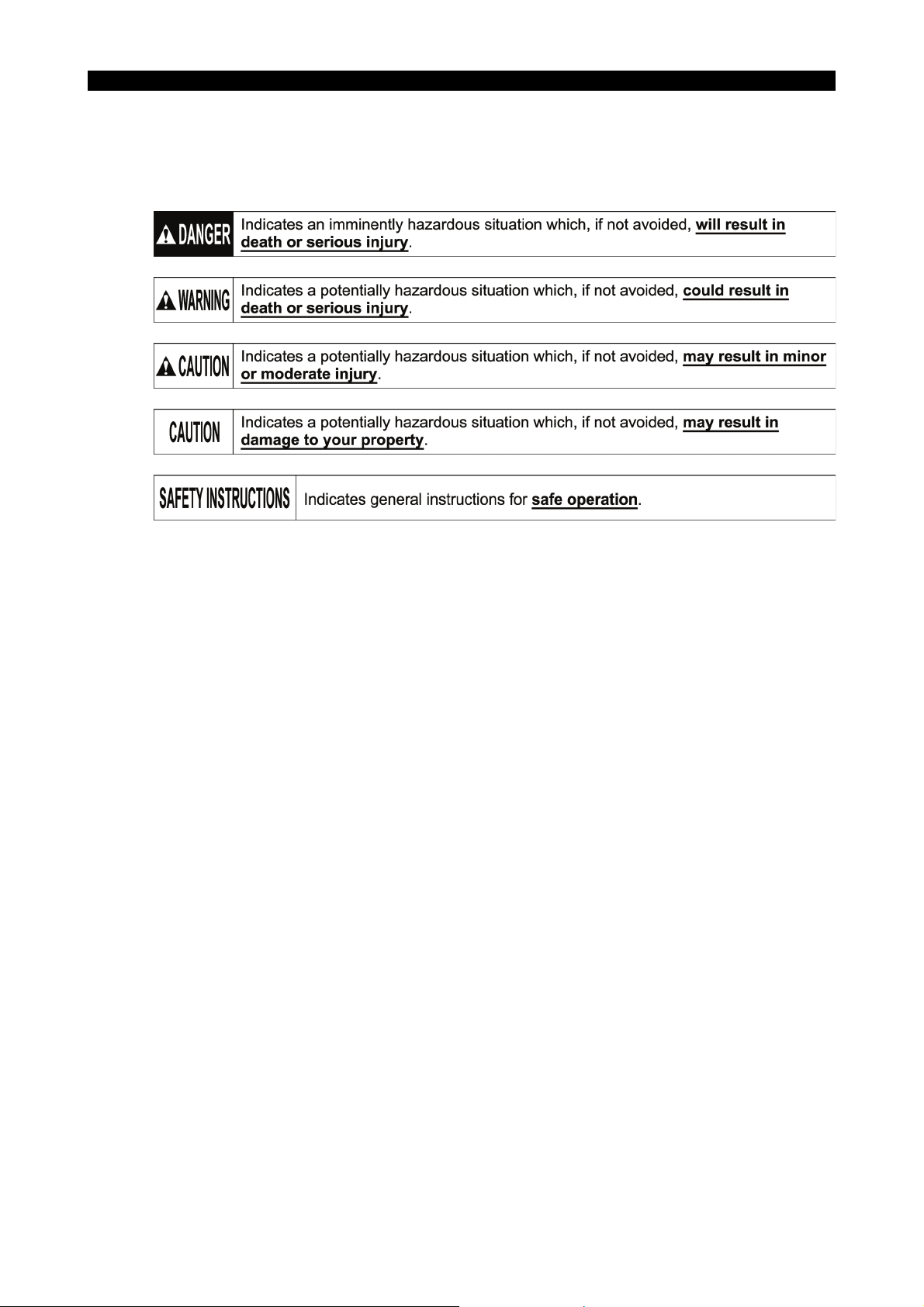
7. Symbols Used in This Manual
The following warning indications are used in this manual to draw attention to information of
particular importance. Read the instructions marked with these symbols carefully and follow them.
5921-E P-(v)
SAFETY PRECAUTIONS
Page 7

5921-E P-(i)
INTRODUCTION
INTRODUCTION
Before using this NC unit, read this manual thoroughly in order to ensure correct use.
This manual explains how to use and maintain the control so that it will deliver its full performance and
maintain accuracy over the long term.
You must pay particular attention to the cautions given in this manual; read them carefully and make sure you
fully understand them before operating the NC.
Page 8

5921-E P-(i)
TABLE OF CONTENTS
TABLE OF CONTENTS
SECTION 1 CLASSIFICATION OF ALARMS ...........................................................1
1-1. Alarm Classifications ......................................................................................................... 1
1-2. Object Number and Object Message ................................................................................ 2
1-2-1. Alarm Codes........................................................................................................ 3
1-2-2. Bit conversion method......................................................................................... 3
1-2-3. How to check alarm contents .............................................................................. 4
SECTION 2 ALARM P...............................................................................................5
SECTION 3 ALARM A.............................................................................................74
SECTION 4 ALARM B...........................................................................................249
SECTION 5 ALARM C...........................................................................................464
SECTION 6 ALARM D...........................................................................................544
SECTION 7 ERROR..............................................................................................645
SECTION 8 APPENDIX ........................................................................................754
8-1. Factor Classification Code/Factor Parameter................................................................ 754
8-1-1. Factor Classification Code/Factor Parameter (for Machine) ........................... 754
Page 9
SECTION 1 CLASSIFICATION OF ALARMS
SECTION 1 CLASSIFICATION OF ALARMS
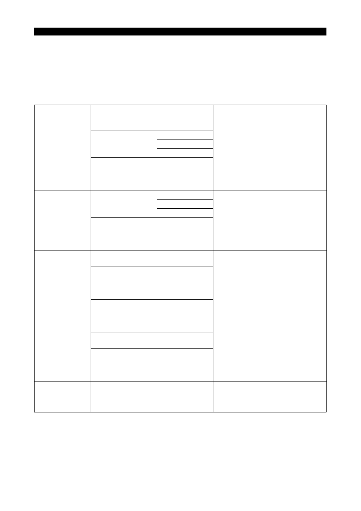
Alarms related with the OSP are classified into five types such as Alarm P, A, B, C and D.
1-1. Alarm Classifications
5921-E P-1
Alarm
P Stops NC operation. All NC functions are inoperative.
A
B The commands in the active block are
C The part program being run is executed to
D This alarm does not have any influence on
Machine Conditions When ALARM Lamp
Comes ON
axis feed
Stops;
Shuts off power supply to X- and Z-axis
servo drives.
Alarm display is displayed on the operation
panel.
Stops;
Shuts off power supply to X- and Z-axis
servo drives.
Alarm display is given on the operation
panel.
completed.
Spindle rotation and coolant supply do not
stop.
Power supply to X- and Z-axis servo drives
is not shut off.
Alarm display is given on the operation
panel.
the end (up to M02 command).
Spindle rotation and coolant supply do not
stop.
Power supply to X- and Z-axis servo drives
is not shut off.
Alarm display is given on the operation
panel.
the machine operation.
Alarm display is given on the operation
panel.
spindle rotation
coolant supply
axis feed Operations for display are possible.
spindle rotation
coolant supply
Operative NC Functions Thereafter
Concerning the control, cancel the alarm
by turning power on again after turning it
off once.
The machine remains inoperative until
the control is reset and the alarm
canceled.
Operations for display are possible.
The machine remains inoperative until
the control is reset and the alarm
canceled.
Operations for display are possible.
No new program can be run until the
control is reset and the alarm is
canceled.
Operations on the operation panel are all
operative. Alarm cannot be canceled
unless the cause of the alarm is
removed.
Page 10
SECTION 1 CLASSIFICATION OF ALARMS
LE37006R0100300020001
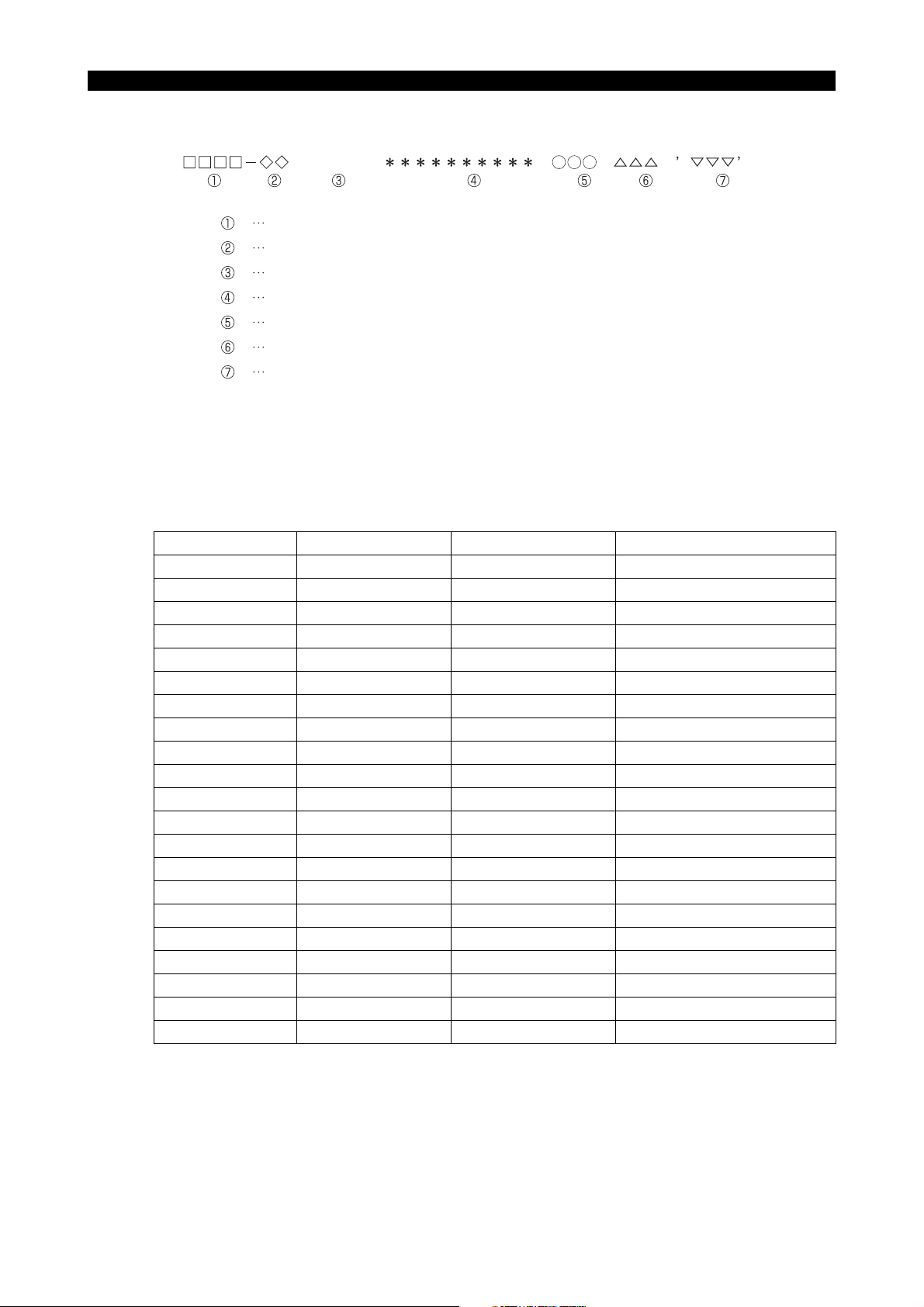
Display Format of Alarm P, A, B, C and D
ALARM-A
Alarm number
Object number
Alarm level
Alarm message
Object message
Alarm code
Alarm character-string
1-2. Object Number and Object Message
The object number and the object message show the programming system and the control axis
where the alarm has occurred by the number and message as shown in the table blow:
5921-E P-2
Object No. Meaning Object message Notes
None No classification None
01 System 1 “A side” or “1-A sd” 1st spindle and turret A
02 System 2 “B side” or “1-B sd” 1st spindle and turret B
03 System 3 “2-A sd” 2d spindle and turret A
04 System 4 “2-B sd” 2d spindle and turret B
11 1st X-axis “XAaxis” or “X-axis”
12 1st Y-axis “YAaxis” or “Y-axis”
13 1st Z-axis “ZAaxis” or “Z-axis”
16 1st W-axis “W-axis”
19 1st C-axis “C-axis” or “Caxis1”
20 1st S-axis “SPDL” or “SPDL-1”
21 1st T-axis “TAaxis” or “T-axis”
22 1st M-axis “MAaxis” or “M-axis”
31 2d X-axis “XBaxis”
32 2d Y-axis “YBaxis”
33 2d Z-axis “ZBaxis”
39 2d C-axis “Caxis2”
40 2d S-axis “SPDL-2” Sub spindle, pick-off spindle
41 2d T-axis “TBaxis”
42 2d M-axis “MBaxis”
53 3d Z-axis “ZCaxis” LT series
As indicated above, the object numbers and messages to be used are determined by the machine
specifications.
Page 11

1-2-1. Alarm Codes
In this manual, alarm codes are explained using such as "X", "XX", and "XXYY".
Explanation is given in the following methods:
(1) The alarm code indicated in this text can be used directly as the key to find the contents of error.
(2) The alarm code indicated in this text should first be converted into bit expression (pattern),
which is then used as the key to find the contents of error.
In the case of 2), the procedure to convert the alarm code into bit pattern is shown below.
1-2-2. Bit conversion method
5921-E P-3
SECTION 1 CLASSIFICATION OF ALARMS
Alarm Code
(Expressed in
hexadecimal)
0 0000 8 1000
1 0001 9 1001
2 0010 A 1010
3 0011 B 1011
4 0100 C 1100
5 0101 D 1101
6 0110 E 1110
7 0111 F 1111
Bit Pattern
Alarm Code
(Expressed in
hexadecimal)
Bit Pattern
Page 12
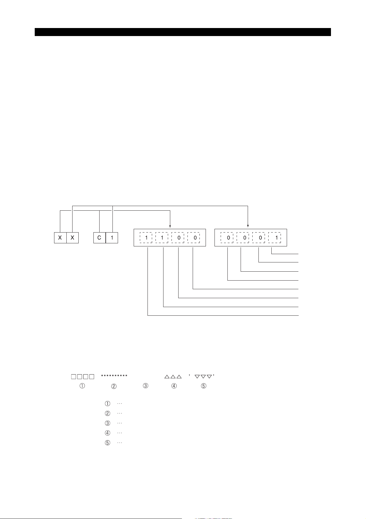
1-2-3. How to check alarm contents
LE37006R0100300060001
The method to find the details of the alarm indicated by the bit pattern is explained below using an
example.
Example:
[Code] XX
XX
bit1->EC I/O power shut off error
bit2->ECC error
bit3->Not used
bit4->Not used
bit5->EDRQ INT signal
bit6->ECP INT signal
bit7->ECP RUN signal
bit0->Battery error
If an alarm occurs, a hexadecimal number is displayed.
If "$C1" is displayed, for example, first convert this "$C1" into bits.
5921-E P-4
SECTION 1 CLASSIFICATION OF ALARMS
After the conversion, it is known that Bit0, Bit6, and Bit7 are ON.
See the information above and you will find that these error codes
correspond to "battery error", "ECP INT signal", and "ECP RUN signal",
respectively.
Error Display Format
ERROR
Error number
Error message
Indication of ERROR
Error code
Error character-string
bit 0
bit 1
bit 2
bit 3
bit 4
bit 5
bit 6
bit 7
Page 13

SECTION 2 ALARM P
0700 NC start-up error ........................................................................................... 10
0701 P100-Menu initialization failure ..................................................................... 10
0702 Power failure upon start-up ........................................................................... 11
0703 Load information file not found ..................................................................... 11
0704 File load error ................................................................................................ 11
0705 Default scheduling table error ....................................................................... 12
0706 Backup data file error .................................................................................... 12
0707 DTL link/unlink error ..................................................................................... 12
0708 RT thread stack overflow .............................................................................. 13
0709 Hardware exception ...................................................................................... 13
0710 System call error ........................................................................................... 13
0711 AlarmService library error .............................................................................14
0712 AlarmService internal error (exception) ........................................................ 14
0713 AlarmService error ........................................................................................ 14
5921-E P-5
SECTION 2 ALARM P
0714 Blue screen ................................................................................................... 14
0715 P100-Menu error ........................................................................................... 15
0716 Floating point exception ................................................................................ 15
0717 PLC control error .......................................................................................... 15
0718 Real time thread time over ............................................................................ 15
0719 HXCP thread error ........................................................................................ 15
0720 AlarmService internal error ........................................................................... 16
0721 DeviceNet error ............................................................................................. 16
0723 DeviceNet I/O data link file read ................................................................... 17
0725 M code data file ............................................................................................ 17
0726 Safety speed data error ................................................................................ 17
0727 MCS firmware doesn't support POS2 unit .................................................... 17
0728 FL-net error ................................................................................................... 18
0729 Non-responsive software detected. .............................................................. 18
0731 R Spec. error ................................................................................................18
0732 Unable to execute lost motion compensation ............................................... 18
0735 MCS DD encoder link error ........................................................................... 18
0736 MCS DD encoder error ................................................................................. 19
0737 MCS DD encoder (slave sensor) detected error ........................................... 19
0738 MCS DD encoder initialization failure ........................................................... 20
0739 MCS DD encoder (slave sensor) initialization failure .................................... 21
0741 MCS firmware version error .......................................................................... 22
0742 Relocation detection error ............................................................................. 22
0744 MCS power supply unit overload .................................................................. 22
Page 14

SECTION 2 ALARM P
0750 The spec.-code or select-soft. was wrong .................................................... 22
0752 VDU communication error ............................................................................ 23
0753 VDU detected error ....................................................................................... 23
0754 VDU initialization failure ................................................................................ 24
0755 SIO link error ................................................................................................. 24
0756 PSC optical scale encoder error ................................................................... 25
0757 MF-SAFETY Error ........................................................................................ 25
0758 Safety I/O Error ............................................................................................. 26
0759 Safety Servo Link Error ................................................................................. 28
0782 Magnetic encoder speed detection error ...................................................... 29
0783 MCS Rotary encoder 5 initialization failure ................................................... 29
0784 MCS Rotary encoder 5 error ......................................................................... 30
0785 MCS Rotary encoder 4 initialization failure ................................................... 30
0786 MCS Rotary encoder 4 error ......................................................................... 30
0787 MCS Rotary encoder 3 initialization failure ................................................... 30
0788 MCS Rotary encoder 3 error ......................................................................... 30
0789 MCS Rotary encoder 2 error ......................................................................... 31
5921-E P-6
0790 MCS Rotary encoder 1 initialization failure ................................................... 31
0791 MCS Rotary encoder 1 error ......................................................................... 31
0792 MCS Linear scale 4 initialization failure ........................................................ 32
0793 MCS Linear scale 4 error .............................................................................. 32
0794 MCS Linear scale 3 initialization failure ........................................................ 32
0795 MCS Linear scale 3 error .............................................................................. 33
0796 MCS Linear scale 2 initialization failure ........................................................ 33
0797 MCS Linear scale 2 error .............................................................................. 33
0798 MCS Linear scale 1 initialization failure ........................................................ 33
0799 MCS Linear scale 1 error .............................................................................. 33
0800 Spindle D/A control data file read ................................................................. 34
0801 TCP/IP board detected error ......................................................................... 34
0802 Load information file not found ..................................................................... 35
0803 File load error ................................................................................................ 35
0804 MSB file mismatch ........................................................................................ 35
0805 MOP-Tool parameter PBU load .................................................................... 35
0806 MOP-Tool tool data PBU load ...................................................................... 35
0807 ACP panel status receipt error ...................................................................... 36
0808 Speed change ratio failure ............................................................................ 36
0810 NC I/O data file read ..................................................................................... 36
0812 MCS initialization error .................................................................................. 36
0813 MCS Communication error ........................................................................... 38
0814 MCS data file corrupt .................................................................................... 39
Page 15

SECTION 2 ALARM P
0815 PLC real-time task loop error ........................................................................ 40
0816 PLC initialization error ................................................................................... 40
0817 MCS error ..................................................................................................... 41
0818 ADP initialization failure ................................................................................ 41
0820 Machine data file read .................................................................................. 41
0821 Spindle gear ratio .......................................................................................... 42
0822 Wheel data file read ...................................................................................... 42
0823 AXIS CONSTRUCTION DATA setting error ................................................. 42
0824 Unit connection mistake ................................................................................ 43
0825 AXIS CONSTRUCTION name not set .......................................................... 43
0826 AXIS CONSTRUCTION DATA file read ....................................................... 43
0827 Control axis not found ................................................................................... 43
0828 Wire feed axis No. error ................................................................................ 43
0833 MCS option program file not sent ................................................................. 44
0834 MCS servo data error ................................................................................... 44
0835 MCS communication error ............................................................................ 44
0836 Program request illegal ................................................................................. 45
5921-E P-7
0837 Loader spec. code data error ........................................................................ 45
0838 Loader backup data file read error ................................................................ 45
0839 Specification conditions failure ..................................................................... 45
0840 SuperHi-NC specification mismatch ............................................................. 46
0841 FCP4 board detected error ........................................................................... 46
0842 Safety monitor spec. error ............................................................................ 46
0845 Specification code setting failure .................................................................. 46
0846 Thermal deviation comp. backup data file read ............................................ 47
0847 DNC-DT preload task start error ...................................................................47
0848 PSCB error ...................................................................................................47
0849 Synchronous axis tandem control initialization failure .................................. 47
0850 MCS Undefined alarm number ..................................................................... 48
0851 MCS Inverter unit fault .................................................................................. 48
0852 Mistake in data from MCS to NC .................................................................. 49
0853 MCS CON APA deviation ............................................................................. 50
0854 MCS Power supply unit error ........................................................................ 50
0855 MCS Converter link error .............................................................................. 51
0856 MCS DC-bus voltage alarm .......................................................................... 51
0857 MCS Motor overcurrent ................................................................................ 51
0858 MCS Power unit overheat ............................................................................. 51
0859 MCS Power unit overload ............................................................................. 52
0860 MCS Supply voltage flutter ........................................................................... 52
0861 MCS Inverter capacity differs from spec. ...................................................... 52
Page 16

SECTION 2 ALARM P
0862 MCS Winding change failure ........................................................................ 52
0863 MCS Encoder link error ................................................................................ 53
0864 MCS Encoder detected error ........................................................................ 53
0865 MCS Encoder initialization failure ................................................................. 54
0866 MCS Encoder with shaft detected error ........................................................ 54
0867 MCS Encoder with shaft initialization failure ................................................. 54
0868 MCS ABSO SCALE error .............................................................................55
0869 MCS ABSO SCALE initialization failure ........................................................ 55
0870 MCS Magnetic encoder alarm ...................................................................... 55
0871 MCS Resolver alarm ..................................................................................... 55
0872 MCS Pulse generator count over .................................................................. 56
0873 MCS Motor overheat ..................................................................................... 56
0874 MCS Servo link error .................................................................................... 56
0875 MCS Servo link disconnection ......................................................................57
0876 Mistake in data from NC to MCS .................................................................. 57
0877 MCS Servo data error ................................................................................... 57
0878 MCS Illegal command ................................................................................... 58
5921-E P-8
0879 MCS CON speed over .................................................................................. 58
0880 MCS Speed command over .......................................................................... 59
0881 MCS DIFF over ............................................................................................. 59
0882 MCS APA speed over ................................................................................... 59
0883 MCS Full-closed APA error ........................................................................... 59
0884 MCS Over speed .......................................................................................... 60
0885 MCS Speed deviation over ........................................................................... 60
0886 MCS Collision detected ................................................................................ 60
0887 MCS Urgent-stop time over .......................................................................... 61
0888 MCS Belt is broken ....................................................................................... 61
0889 MCS Axis change control error ..................................................................... 61
0890 MCS Independent encoder initialization failure ............................................ 61
0891 MCS Calculated current position lies outside range ..................................... 62
0892 MCS Motor overload ..................................................................................... 62
0893 MCS Safety speed monitor E-Link error ....................................................... 62
0894 MCS ABSO SCALE sub-slider detected error ..............................................62
0895 MCS Tandem control communication error .................................................. 63
0896 MCS Full abso scale link error ...................................................................... 63
0897 MCS Full abso scale error ............................................................................ 64
0898 MCS Full abso scale initialization failure ...................................................... 64
0899 MCS Axis stop signal error ........................................................................... 65
0940 Time sharing task control .............................................................................. 65
0941 Real-time task control ................................................................................... 65
Page 17

SECTION 2 ALARM P
0942 Real-time task loop error .............................................................................. 65
0943 Main processor name incorrect .................................................................... 66
0944 Slave processor name incorrect ................................................................... 66
0945 Memory board/battery life ............................................................................. 66
0951 SMP error ..................................................................................................... 66
0952 Not equipped with processor board .............................................................. 67
0954 Peripheral processor start ............................................................................. 67
0955 Spec. code: data file ..................................................................................... 67
0956 Backup data file read .................................................................................... 68
0957 Graphic backup data file read ....................................................................... 68
0958 Pitch compensation data file read ................................................................. 68
0965 Configuration file format error ....................................................................... 69
0971 Cache data: Initialization error ...................................................................... 69
0988 Cache data: Operation error ......................................................................... 69
0989 CPU information table data incorrect ............................................................ 69
0990 TASK generate error ..................................................................................... 70
0991 TASK information table data incorrect ..........................................................70
5921-E P-9
0992 PLC backup data file read ............................................................................ 70
0993 TCP/IP board illegal ...................................................................................... 71
0994 TCP/IP configuration file ............................................................................... 71
0995 Machine axis data file ................................................................................... 71
0996 PLC axis data file .......................................................................................... 71
0997 PLC monitor backup data file read ............................................................... 72
0998 PLC sequence program load ........................................................................ 72
0999 Synchronous tap data file read ..................................................................... 73
Page 18

0700 NC start-up error
An error occurred when NC started up.
[Object]
None
[Character-string]
None
[Code]
0x10000000: NC Configuration read error
0x10003000: Spec code read error
0x20000000: ServoLink board initializing error
0x3XXX00YY: NC data file read error
XXX:
0x002: HD backup status file
0x004: Parameter data file
0x008: Machine data file
0x010: PLC backup data file
0x020: PLC-HMI data file
0x040: Alarm History data file
0x080: PLC AXIS data pbu file
0x100: POT TOOL data pbu file (M/C only)
0x200: MOP TOOL Tool data file (M/C only)
0x400: MOP TOOL Parameter file (M/C only)
0x800: Thermal deviation compensation data file
YY:
0x01: File read open error
0x02: File read error
0x03: Version check error
0x04: Check sum error
0x05: Double check sum error
0x06: Backupped Memory error
0x07: File write open error
0x08: File write error
0x40000000: Axis information initializing error
-More than 8 axis
0x50000000: PLC data file read error
-Read failed M code data file
0x60000000: I/O Initializing error
-PLC variable backup file read error
-I/O forced data file read error
0x70000000: ServoLink Initializing error
0x80000000: Operation buffer get error
0x90000000: PBU data file read error
0xA0000000: Shared memory size definition error
0xA1XXXXXX: AlarmService start error
XXXXXX: Error code of AlarmService library function
0xA2400002: Alarm History read error
0xA3000000: Thread monitor initializing error
0xA9000000: Initialization processing of the safety logic was not completed within 20 seconds
0xA9000001: Axis construction definition file open error
0xA9000002: Axis construction definition file read error
0xA9000003: Axis construction definition file mismatch
0xFFFFFFFF: Debug information file read error
5921-E P-10
SECTION 2 ALARM P
0701 P100-Menu initialization failure
An error occurred in P100-Menu while system startup.
[Object]
None
[Character-string]
None
[Code]
1: NC Control file was not found.
2: PLC Control file was not found.
3: NC-HMI was not found
Page 19

4: 3D real sim file was not found.
5: MacMan file was not found.
6: Version mismatch between P100-Menu and PLC Control
7: Version mismatch between P100-Menu and MacMan
8: Version mismatch between P100-Menu and NC Control
11: Conf-P100-menu read error
12: An error occurred at RTOS
13: An error occurred at UPS Service
21: NC Control start failure
22: Error in obtaining shared objects
23: PLC Control start failure
24: NC-HMI start failure
25: 3D real sim start failure
26: MacMan start failure
101: Startup sequence 0x10 receive failure
200: Startup sequence 0x10 send failure
201: Startup sequence 0x20 receive failure
300: Startup sequence 0x20 send failure
301: Startup sequence 0x30 receive failure
400: Startup sequence 0x30 send failure
401: Startup sequence 0x60 receive failure
500: Startup sequence 0x60 send failure
501: Startup sequence 0x70 receive failure
600: Startup sequence 0x70 send failure
601: Startup sequence 0x7C receive failure
700: Startup sequence 0x7C send failure
701: AlarmService start failure
702: Activation sequence 0x80 receive failure
[Probable Faulty Locations]
1.Execution file name failure
2.Data file name failure
3.RTOS failure
4.UPS function failure
5.Software failure
6.Software Version failure
5921-E P-11
SECTION 2 ALARM P
0702 Power failure upon start-up
[Object]
None
[Character-string]
None
[Code]
None
[Probable Faulty Locations]
1.Power failure during while system startup
2.Power shutoff during while system startup
0703 Load information file not found
A load information file was not found.
[Object]
None
[Character-string]
None
[Code]
None
0704 File load error
An object file was not loaded correctly.
[Object]
None
[Character-string]
Page 20

None
[Code]
1:A file was not found
2:The attribute of file was not correct.
3:The load address information of file was not correct
4:An error occurred when file was loaded
FFFFFFFF:The details of alarm was displayed by message from OS
0705 Default scheduling table error
A default scheduling table error was detected.
[Object]
None
[Character-string]
None
[Code]
0x00010001: RTIN default scheduling table error (element number)
0x00010002: RTIN default scheduling table error (end element)
0x00020001: TSMN default scheduling table error (element number)
0x00020002: TSMN default scheduling table error (initial attribute)
[Probable Faulty Locations]
1.NC software failure
0706 Backup data file error
5921-E P-12
SECTION 2 ALARM P
Error occurred when load/save the backup file.
[Object]
None
[Character-string]
None
[Code]
XXXXYYYY
XXXX
0x0002:HD backup status file
0x0004:Low speed NC backup data file
0x0008:High speed NC backup data file
0x0010:PLC backup data file
0x0020:PLC-HMI data file
0x0040:Alarm history data file
0x0080:PLC axis data file
0x0100:POT TOOL data file
0x0200:MOP TOOL Tool data file (M/C only)
0x0400:MOP TOOL Parameter data file (M/C only)
0x0800:Thermal deviation compensation data file
YYYY
1:File read open error
2:File read error
3:Version check error
4:Check sum error
5:Double check sum error
6:Backup memory check error
7:File write open error
8:File write error
0707 DTL link/unlink error
An error occurred in DTL link or unlink.
[Object]
None
[Character-string]
None
[Code]
1:RTIN refresh error
Page 21

2:TSMN refresh error
[Probable Faulty Locations]
1.Hardware failure
2.Software failure
0708 RT thread stack overflow
Stack overflow of RT thread was detected.
[Object]
None
[Character-string]
Occurred RT thread name
[Code]
None
[Probable Faulty Locations]
1.NC software failure
0709 Hardware exception
Hardware exception was occurred.
[Object]
None
[Character-string]
Occurred RT thread name
[Code]
Hardware exception code
0x5555: CPU Diagnose error
0x8100:Divide by 0 error
0x8101:Unexpected Single Step Interrupt
0x8102:Unexpected NMI
0x8103:Unexpected Debug Interrupt
0x8104:Overflow error
0x8105:Array Bounds error
0x8106:Invalid Opcode error
0x8107:NPX Device not present
0x8108:Double Fault error
0x8109:Unknown Device error
0x810A:Invalid TSS error
0x810B:Segment not Present error
0x810C:Stack Fault error
0x810D:General Protection error
0x810E:Page Fault error
0x8110:Unknown Device error 1
0x8111:Alignment error
[Probable Faulty Locations]
1.Hardware failure
2.Software failure
[Note]
Alarm information is also displayed also in the console window.
5921-E P-13
SECTION 2 ALARM P
0710 System call error
An error occurred in the INtime system call.
[Object]
None
[Character-string]
Occurred RT thread name
[Code]
XXXXYYYY
XXXX:INtime system call code
YYYY:Return value or status of INtime system call
[Probable Faulty Locations]
Page 22

NC software failure
[Note]
Alarm information is also displayed also in the console window.
0711 AlarmService library error
An error occurred in the AlarmService library function.
[Object]
None
[Character-string]
Occurred thread name
[Code]
XXYYYYYY
XX:AlarmService library function code
YYYYYY:AlarmService library function error code
[Probable Faulty Locations]
NC software failure
[Note]
Alarm information is also displayed also in the console window.
0712 AlarmService internal error (exception)
An error occurred inside of AlarmService.
[Object]
None
[Character-string]
"ALMS"
[Code]
AlarmService internal error code
[Probable Faulty Locations]
NC software failure
[Note]
Alarm information is also displayed also in the console window.
5921-E P-14
SECTION 2 ALARM P
0713 AlarmService error
P100-Menu detected AlarmService error.
[Object]
None
[Character-string]
None
[Code]
None
[Probable Faulty Locations]
1.NC software failure
0714 Blue screen
Blue screen (kernel stop error) occurred.
[Object]
None
[Character-string]
None
[Code]
None
[Probable Faulty Locations]
1.Win32 application failure
2.Windows failure
3.Windows driver failure
Page 23

0715 P100-Menu error
An abnormal condition of P100-Menu was detected.
[Object]
None
[Character-string]
None
[Code]
None
[Probable Faulty Locations]
1.P100-Menu failure
0716 Floating point exception
Floating point exception was occurred.
[Object]
None
[Character-string]
Occurred RT thread name
[Code]
XXXXYYZZ
XXXX:Exception code
YY:Not used (0 fixed)
ZZ:FPU status word
bit5:PE (Precision Exception Flag)
bit4:UE (Underflow Exception Flag)
bit3:OE (Overflow Exception Flag)
bit2:ZE (Zero Divide Exception Flag)
bit1:DE (Denormalized Operand Exception Flag)
bit0:IE (Invalid Operation Exception Flag)
[Probable Faulty Locations]
NC software failure
5921-E P-15
SECTION 2 ALARM P
0717 PLC control error
Error occurred on PLC Control.
[Object]
None
[Character-string]
None
[Code]
XXXXYYYY
XXXX:PLC Control status
YYYY:PLC Control error code
[Probable Faulty Locations]
1.PLC software failure
0718 Real time thread time over
Real time-type thread did not finish within the stated time
[Object]
None
[Character-string]
RT thread name that was exceeded the stated time
[Code]
None
[Probable Faulty Locations]
1.NC software failure
0719 HXCP thread error
Page 24

An abnormal condition of HXCP thread was detected.
[Object]
None
[Character-string]
None
[Code]
None
[Probable Faulty Locations]
1.NC software failure
0720 AlarmService internal error
An error occurred inside of AlarmService.
[Object]
None
[Character-string]
"ALMS"
[Code]
AlarmService internal error code
[Probable Faulty Locations]
1.NC software failure
2.P100-Menu failure
5921-E P-16
SECTION 2 ALARM P
0721 DeviceNet error
Error occurred on DeviceNet.
[Index]
None
[Character-string]
CH* SC$
* : Channel number where the error occurred.
S : Sequence counter
[Code]
XXYYZZZZ
XX Slave station MacID where the error occurred
YY Slave station
0x00 Normal or nonexistent slave station
0x46 Duplicate MacID error
0x48 Communication stop
0x49 Discrimination information was not compatible with scan list
0x4D Data size was not compatible with scan list
0x4E No response in the connection check.
0x4F Other slave stations are nonexistence on network
0x50 Idle condition
0x53 Error received in the connection check
0x54 Timeout occurred in the connection check
0x56 Turn into the idle mode
0x5B Bus off
0x5C Network power supply off
( XXXX became 0xFFFF,if its not caused by slave station, such as communication delay.)
ZZZZ Scanner error status
bit 0 Memory check error
bit 1 Scan list initialize error
bit 2 Scan list mismatch error(MacID)
bit 3 Scan list mismatch error(Input data)
bit 4 Scan list mismatch error(Output data)
bit 5 Duplicate MacID error
bit 6 Network power supply status error
bit 7 Memory parity error
bit 8 Input data reception error(single)
bit 9 Input data reception error(dowble)
bit10 Output data transmission error(single)
bit11 Output data transmission error(dowble)
Page 25

bit12 Slave station communication delay error(single)
bit13 Slave station communication delay error(dowble)
bit14 Bus off
bit15 Diagnostic information access error
[Probable Faulty Locations]
1)Hardware failure
2)Software failure
0723 DeviceNet I/O data link file read
The NC failed to read DeviceNet IO data link file.
[Code]
I/O data file load status (in hexadecimal)
2 ->File open error (no file)
3 ->File read error (no data)
4 ->File attribute error (not "PBU1")
5 ->File close error
6 ->File size error (too small)
7 ->File size error (too large)
100->Wrong PLC machine type
200->Wrong PLC class
300->Wrong file version
1002 ->DN SCAN LIST CHANGE FILE OPEN ERROR
1003 ->DN SCAN LIST CHANGE FILE READ ERROR (NO DATA)
1004 ->DN SCAN LIST CHANGE FILE ATTRIBUTE ERROR (NO 'PBU1')
1005 ->DN SCAN LIST CHANGE FILE CLOSE ERROR
1006 ->DN SCAN LIST CHANGE FILE SIZE ERROR (SIZE SMALL)
5921-E P-17
SECTION 2 ALARM P
0725 M code data file
Establishment data of reading M-code file is bad.
[Code]
1->The denial data is bad.
[Character string]
The number is M-code which is established bad data.
[Measures to Take]
Please correct the bad data of M-code.
0726 Safety speed data error
The safety speed data was in abnormal state in the machine without the CE marking safety speed monitor.
[Index]
Axis name or none (spindle)
[Character-string]
None
[Code]
X
X=1:The guard number of the safety speed data was outside the range from -0 to 9.
[Measures to Take]
Change the safety speed monitor data file for axis control.
Relevant specifications:Without CE mark safety speed monitor type
[Related Specifications]
Without CE mark safety speed monitor type
0727 MCS firmware doesn't support POS2 unit
This alarm occurs when the firmware ROM version of the NC axis/ machine(PLC) axis MIV unit is not 511 or later when the new
POS unit is installed.
[Character-string]
None
[Code]
None
Page 26

0728 FL-net error
An error occurred during startup of the FL-net card.
[Object]
None
[Character-string]
None
[Code]
Y000XXX
Y:0
XXXX:
7F00:System error
7F01:Flash memory error
7F02:DRAM test error
7F03:NICE test error
7F04:EEPROM sum check error
7F05:CPU BUS error
7F06:illegal Instruction
Y:1
XXXX:
0004:Timeout error for 4 sec or longer
Y:F
XXXX:
FFFF: FL-net card is not mounted
[Probable Faulty Locations]
FL-net card is defective.
5921-E P-18
SECTION 2 ALARM P
0729 Non-responsive software detected.
Non-answered software was detected.
[Object]
None
[Character-string]
None
[Code]
NT Process name
[Probable Faulty Locations]
NC software failure
0731 R Spec. error
It is the illegal of "R SPEC".
[Index]
None
[Code]
1:"NON R SPEC" of NC is OFF, and "R-SPEC" of SVDN-ID is OFF.
2:"NON R SPEC" of NC is ON, and "R-SPEC" of SVDN-ID is ON.
3:When there are 2 SVDN-boards in the machine, "R-SPEC" of one board is ON, other is OFF.
4X:"NON R SPEC" of NC is OFF, and "R-SPEC" of SVDN-ID is ON, and Restriction-Spec is ON.
0732 Unable to execute lost motion compensation
0735 MCS DD encoder link error
An error occurred in the encoder communication link.
[Object]
Axis name or none (spindle)
[Character-string]
None
[Code]
XXYYZZZZ
Page 27

XX = $FF (fixed)
YY = $00: Error is detected at the DD encoder.
$01: Error is detected at the DD encoder(slave sensor).
ZZZZ = Encoder link error status at the time of error detection
bit15: Undefined
bit14: Undefined
bit13: Error in communication with the DD encoder (slave sensor)
bit12: Error in communication with the DD encoder
bit11: MT buffer error
bit10: Transmission loop error in AT mode
bit9 : Data over error in data receiving part of interface
bit8 : Undefined
bit7 : Undefined
bit6 : Modulation code error
bit5 : CRC error
bit4 : Format error
bit3 : Double transmission error
bit2 : Double reception error
bit1 : Parity error
bit0 : Time-out error
This alarm occurs only at ICB-H.
[Probable Faulty Locations]
DD encoder of DD encoder (slave sensor) of the pertinent axis Encoder link cables or connectors Inverter unit control board
0736 MCS DD encoder error
5921-E P-19
SECTION 2 ALARM P
The DD encoder has become undetectable.
[Object]
Axis name or none (spindle)
[Character-string]
None
[Code]
XXYYZZZZ
XX = Positional data status
bit7 : Error bit (1:error)
bit6 : Absolute position sensor margin error.(0:Normal, 1:Warning)
bit5 : Gap-Warning (1:Gap-small,Toggle:Gap-big)
bit4 : Inclination-Warning (1:CCW-big, Toggle:CW-big)
bit3 : Auto set mode (0:Normal, 1:Auto mode)
bit2 : Communication error (Toggle by detecting)
bit1,0: Error bit number of absolute position code.(It is indicated by 2bits.)
YY = Alarm code
01: Stop command has stopped.
02: Control parameter error
04: Absolutization error
05: Initialization speed too high
08: Auto-set-data error
0D: Speed too high
0E: Synchronization error
20: Absolutization mismatch (Only Format-5)
21: Communication-error of Master-sensor (Only Format-5)
3E: Code-error by Absolute-position-sensor
3F: Check-errotr by Absolute-position-code
40: Inclination-error (for plus)
41: Inclination-error (for minus)
42: Gap is narrow
43: Gap is wide
ZZZZ = 0000 fixed
This alarm occurs only at ICB-H.
[Probable Faulty Locations]
DD encoder
0737 MCS DD encoder (slave sensor) detected error
The DD encoder (slave sensor) has become undetectable.
Page 28

[Object]
Axis name or none (spindle)
[Character-string]
None
[Code]
XXYYZZZZ
XX = Positional data status
bit7 : Error bit (1:error)
bit6 : Absolute position sensor margin error.(0:Normal, 1:Warning)
bit5 : Gap-Warning (1:Gap-small,Toggle:Gap-big)
bit4 : Inclination-Warning (1:CCW-big, Toggle:CW-big)
bit3 : Auto set mode (0:Normal, 1:Auto mode)
bit2 : Communication error (Toggle by detecting)
bit1,0: Error bit number of absolute position code.(It is indicated by 2bits.)
YY = Alarm code
01: Stop command has stopped.
02: Control parameter error
04: Absolutization error
05: Initialization speed too high
08: Auto-set-data error
0D: Speed too high
0E: Synchronization error
20: Absolutization mismatch (Only Format-5)
21: Communication-error of Master-sensor (Only Format-5)
3E: Code-error by Absolute-position-sensor
3F: Check-errotr by Absolute-position-code
40: Inclination-error (for plus)
41: Inclination-error (for minus)
42: Gap is narrow
43: Gap is wide
ZZZZ = 0000 fixed
This alarm occurs only at ICB-H.
[Probable Faulty Locations]
DD encoder (slave sensor)
5921-E P-20
SECTION 2 ALARM P
0738 MCS DD encoder initialization failure
An error occurred in the initialization of the DD encoder.
[Object]
Axis name or none (spindle)
[Character-string]
None
[Code]
XXYYZZZZ
XX = Encoder link initialization sequence number (1B) at the time of the error detection
0: Reset
1: Network address setting
2: Request to send the basic information for communication
3: Change of communication software version
4: Acquisition of device information
5: Parameter change
6: Position detection start
7: AT mode start
YY = Error content (1B)
0: Communication error
1: Transmission start time over
2: Transmission finish time over
3: Reception finish time over
4: Abnormal response address
5: Abnormal response code
6: Parameter error
ZZZZ = Data (2B)
If YY = 0,
The encoder link error status C2ERR at the time of error detection appears.
If YY = 1, 2 or 3,
Page 29

The transmitted frame information QC2MTINF appears.
If YY = 4,
The network address of the responding device appears.
If YY = 5,
Alarm code + positional data status
Refer to MCS DD Encoder error (alarm 1136).
If YY = 6,
Parameter number at which the error is detected
1: Reception of insufficient number of parameters
2: Basic information for communication being incompatible
3: Multi-turn detection range over
4: Communication protocol version being incompatible
5: Positional data format being incompatible
6: Abbreviated data mode being incompatible
However, when abnormal voltage is detected at the encoder fuse
XXYY = $FFFF fixed
ZZZZ = Detected voltage value of the encoder fuse (12[V] = $9980)
Normal range: 10.6[V] to 13.8[V]
Allowable range: $8800 to $B000
This alarm occurs only at ICB-H.
[Probable Faulty Locations]
DD encoder
Encoder link cables and connectors
Inverter unit control board
5921-E P-21
SECTION 2 ALARM P
0739 MCS DD encoder (slave sensor) initialization failure
An error occurred in the initialization of the DD encoder (slave sensor).
[Index]
Axis name or none (spindle)
[Character-string]
None
[Code]
XXYYZZZZ
XX = Encoder link initialization sequence number (1B) at the time of the error detection
0: Reset
1: Network address setting
2: Request to send the basic information for communication
3: Change of communication software version
4: Acquisition of device information
5: Parameter change
6: Position detection start
7: AT mode start
YY = Error content (1B)
0: Communication error
1: Transmission start time over
2: Transmission finish time over
3: Reception finish time over
4: Abnormal response address
5: Abnormal response code
6: Parameter error
ZZZZ = Data (2B)
If YY = 0,
The encoder link error status C2ERR at the time of error detection appears.
If YY = 1, 2 or 3,
The transmitted frame information QC2MTINF appears.
If YY = 4,
The network address of the responding device appears.
If YY = 5,
Alarm code + positional data status
Refer to MCS DD Encoder error (alarm 1136).
If YY = 6,
Parameter number at which the error is detected
1: Reception of insufficient number of parameters
2: Basic information for communication being incompatible
3: Multi-turn detection range over
Page 30

4: Communication protocol version being incompatible
5: Positional data format being incompatible
6: Abbreviated data mode being incompatible
However, when abnormal voltage is detected at the encoder fuse
XXYY = $FFFF fixed
ZZZZ = Detected voltage value of the encoder fuse (12[V] = $9980)
Normal range: 10.6[V] to 13.8[V]
Allowable range: $8800 to $B000
This alarm occurs only at ICB-H.
[Probable Faulty Locations]
DD encoder (slave sensor)
Encoder link cables and connectors
Inverter unit control board
0741 MCS firmware version error
The MCS software version was not correct.
[Object]
None
[Code]
1-> The MCS software version of the XA axis is not since ICBH590 in the premium thread cutting function spec.
[Probable Faulty Locations]
Specification code error
MCS software version error
[Measures to Take]
Reinstall the software or reissue the install disk.
MCS software Upgrade
5921-E P-22
SECTION 2 ALARM P
0742 Relocation detection error
Relocation detection error occurred
[Character-string]
ComErr :Communication error
PBU :PBU data error
PJ :PJ discord
PwdTout :Password application timeout
PwdChk :Password check error
PwdTerm:Password application terminate
[Code]
ComErr:
bit2 Atmega error
bit1 RTC error
bit0 Relocation detection module error
PwdChk:
Password check error code
0744 MCS power supply unit overload
Power Supply Unit over load
[Object]
Axis name or none (spindle)
[Character-string]
None
[Code]
1(fixed)
[Probable Faulty Locations]
Power unit
Overload operation
0750 The spec.-code or select-soft. was wrong
The combination of NC-software and PLC-software was wrong.
Or, the combination of specification-code was wrong.
Page 31

SECTION 2 ALARM P
[Object]
None
[Character-string]
None
[Code]
1:PLC-software is not effective for the specification of "TOOL OFFSET 999"
4:It can't be combined with spindle command unit 0.1.
5:Overlapped PLC axis number
[Probable Faulty Locations]
(1)Mistake of select for specification-code
(2)Mistake of select for PLC-software-version
0752 VDU communication error
An error occurred in the VDU(Vibration Detect Unit) communication link, disabling the VDU from detecting acceleration.
[Object]
Axis name or none (spindle)
[Character-string]
None
[Code]
XXYYZZZZ
XX = FF [HEX] (fixed)
YY = 00 [HEX] (fixed)
ZZZZ = VDU link error status at the time of error detection.
(Each bit represents the kind of communication error.)
bit 15 Undefined
bit 14 Undefined
bit 13 Undefined
bit 12 1: Error in communication with VDU(AT mode)
bit 11 1: Error in communication with VDU(MT mode)
bit 10 1: Transmission loop error in AT (auto) mode
bit 9 1: Data over error in data receiving part of interface
bit 8 Undefined
bit 7 Undefined
bit 6 1: Modulation code error
bit 5 1: CRC error
bit 4 1: Format error
bit 3 1: Double transmission error
bit 2 1: Double reception error
bit 1 1: Modulation code error
bit 0 1: Time-out error
[Probable Faulty Locations]
- VDU
- Encoder link cables
- VFA unit
5921-E P-23
0753 VDU detected error
The VDU(Vibration Detect Unit) has become unable to detect acceleration data.
[Object]
Axis name or none (spindle)
[Character-string]
None
[Code]
XXYYZZZZ
XX = VDU error status
bit7 1: Error bit (1 is error)
bit6 1: Empty bit
bit5 1: Latest acceleration data is overflow(Y axis)
bit4 1: Latest acceleration data is overflow(X axis)
bit3 1: Empty bit
bit2 1: Error in communication (toggled detecting each error)
bit1 1: Previous acceleration data is overflow(Y axis)
Page 32

bit0 1: Previous acceleration data is overflow(X axis)
YY = VDU alarm code
01: Stop command halt
02: Control parameter error
07: User parameter check sum error
0E: Synchronous miss error
15: Acceleration sensor signal error (X axis)
16: Acceleration sensor signal error (Y axis)
17: Acceleration sensor signal error (X and Y axis)
ZZZZ= 0 (fixed)
[Probable Faulty Locations]
- VDU
0754 VDU initialization failure
An error occurred in initialization of VDU(Vibration Detect Unit).
[Object]
Axis name or none (spindle)
[Character-string]
None
[Code]
XXYYZZZZ
XX = Encoder link sequence number at the time of error detection
0: Reset
1: Network address setting
2: Request of basic information on communication
3: Change of communication version
4: Acquisition of device information
5: Parameter change
6: AT (auto) mode start
YY = Error content
0: Communication error
1: Transmission start time over
2: Transmission finishes time over
3: Reception finishes time over
4: Abnormal response address
5: Abnormal response code
6: Parameter error
ZZZZ = Additional data
If YY=0,
the encoder link error status C2ERR at the time of error detection appears.
If YY=1, 2, or 3,
the transferred frame information C2MTINF appears.
If YY=4,
the network address of the responding device appears.
If YY=5,
the received frame information C2RXINF appears.
If YY=6,
the number of parameter that caused the alarm appears.
1 = Not all the necessary parameters are received.
2 = Basic information on communication is incompatible.
4 = Protocol version on communication is incompatible.
[Probable Faulty Locations]
- VDU
- Encoder link cables
- VFA unit
5921-E P-24
SECTION 2 ALARM P
0755 SIO link error
An error occurred in the SIO link.
[Object]
None
[Character-string]
None
Page 33

[Code]
During steady processing
FFFFFFFF:
Recieved the same data from MFU twice
XXXXYYYY:
XXXX: command & data length
0303: recieved error with frame 0
YYYY:The second byte of reception data
1303: recieved error with frame 1
YYYY:The second byte of reception data
05FF: Error status besides 0
YYYY:Error status
During setup processing
XXYYZZZZ:
XX: frame
YY: command
00: reset
01: intelligence
02: time-out time setting
05: file-transfer
ZZZZ: error cause
0007: Data reception response is not sent within 0.15 second after data transmission.
0008: Data transmission does not end within 0.15 second.
0009: Communication error occurred after reception of data.
000A: Communication error occurred while the NC was waiting for data reception.
000B: Communication error occurred while the NC was waiting for data transmission.
000C: Data transmission was attempted during data transmission.
000D: Data transmission was attempted in the state of communication error.
000E: An error command was received.
000F: Transmission command and reception command were not same.
[Probable Faulty Locations]
1.SSIO card
2.Safety module
3.I/O slave
5921-E P-25
SECTION 2 ALARM P
0756 PSC optical scale encoder error
An error was detected by the position encoder of optical scale.
[Character-string]
None
[Code]
XXYYZZ
XX:Value of the J-type endoder and value of the optical scale are too different.
bit1:It is too different by a negative sign.
bit0:It is too different by a positive sign.
YY:Pulse count value of optical scale
bit0:A-phase pulse and B-phase pulse have changed at the same time.
ZZ:The amplitude of the optical scale signal is wrong.
bit1:The amplitude of B-phase is wrong.
bit0:The amplitude of A-phase is wrong.
[Probable Faulty Locations]
- Breakdown of optical scale
- Breakdown of optical scale cable
[Measures to Take]
- Exchange of optical scale
- Exchange of optical scale cables
0757 MF-SAFETY Error
An error was detected by the MF-SAFETY.
[Object]
None
[Character-string]
None
Page 34

[Code]
0x1000XXXX->CPU Exception was occurred in the MF-SAFETY
XXXX->Exception number
0x1100XXXX->NMI was occurred in the MF-SAFETY
XXXX->NMI code
bit15->An error was occurred
bit9 ->Voltage drop for CPU1
bit8 ->Watchdog timer overflow in CPU0
bit1 ->Voltage drop for CPU0
bit0 ->Watchdog timer overflow in CPU1
0x1200XXXX->CPU bus error was occurred in the MF-SAFETY
XXXX->CPUID
bit15->CPUID (0:CPU0, 1:CPU1)
0x130000XX->No response in CPU1 request
XX->CPU1 request number
0x170000XX->Normal process in the MF-SAFETY did not end within a specific period.
XX->End time of normal process (1bit=62.5us)
0x1800XXXX->An Error was detected by the MF-SAFETY
XXXX->Error Code
bit15->MFU I/O unit error
bit14->MFU I/O Bus parity error
bit12->Synchronization error
bit11->Wrongly set synchronous signal timing
0x19000000->Stack overflow in the MF-SAFETY CPU
0x1A00XXXX->Illegal address is in the label table
XXXX->Index of label table
0x1B000000->NC starts up with software update mode in the MF-SAFETY
0x1C0000XX->Mode setting is mismatch between NC and MF-SAFETY
XX->Mismatch location
01->MF-SAFETY mode setting is wrong
02->NC mode setting is wrong
[Probable Faulty Locations]
MF-SAFETY
MF-SAFETY mode setting
NC mode setting
I/O unit in MFU
[Measures to Take]
Replace the MF-SAFETY unit
Replace the I/O unit in MFU
Switch(SW1) of the MF-SAFETY turns off
Update the MF-SAFETY software (safety logic)
5921-E P-26
SECTION 2 ALARM P
0758 Safety I/O Error
An error occurred in Safety IO link (SIO link) or in safety I/O unit.
[Object]
None
[Character-string]
None
[Code]
0x20000000->Safety transmission data was mismatch between CPU0 and CPU1while initialization of SIO link
0x21XX0000->Command was not received while initialization of SIO link
XX->Expecting command
00->Reset Command
01->Information gathering Command
02->Time-out time setting Command
0x22XXYYYY->Communication error was occurred while initialization of SIO link
XX->Expecting command
00->Reset Command
01->Information gathering Command
02->Time-out time setting Command
YYYY->SIO controller error status
bit15->An error was occurred
bit10->Reception buffer size setting was too big
bit9 ->Disconnection error
Page 35

bit8 ->Modulation code error
bit7 ->CRC error
bit6 ->Format error
bit5 ->Double transmission error
bit4 ->Double reception error
bit3 ->Parity error was occurred when SIO controller read transmission buffer
bit2 ->Parity error was occurred when CPU read transmission buffer
bit1 ->Parity error was occurred when CPU read reception buffer
bit0 ->Time-out error
0x23XXYYYY->Error command was received while initialization of SIO link
XX->SIO link slave address which error was detected
YYYY->Error status
bit15->An error was occurred
bit10->Reception buffer size setting was too big
bit9 ->Disconnection error
bit8 ->Modulation code error
bit7 ->CRC error
bit6 ->Format error
bit4 ->Double reception error
bit3 ->Parity error was occurred when SIO controller read transmission buffer
bit2 ->Parity error was occurred when CPU read transmission buffer
bit1 ->Parity error was occurred when CPU read reception buffer
bit0 ->Time-out error
0x24XX00YY->Illegal command was received while initialization of SIO link
XX->Expecting command
XX->Reception command
0x25XX0000->Safety IO slave information did not match the scan file list
XX->Mismatch frame offset
0x2F000000->SIO link was disconnected
0x31000000->The command was not received within a specific period
0x3200XXXX->Communication error was detected by the MF-SAFETY
XXXX->SIO controller error status
bit15->An error was occurred
bit10->Reception buffer size setting was too big
bit9 ->Disconnection error
bit8 ->Modulation code error
bit7 ->CRC error
bit6 ->Format error
bit5 ->Double transmission error
bit4 ->Double reception error
bit3 ->Parity error was occurred when SIO controller read transmission buffer
bit2 ->Parity error was occurred when CPU read transmission buffer
bit1 ->Parity error was occurred when CPU read reception buffer
bit0 ->Time-out error
0x33XXYYYY->Error command was received in SIO link safety frame
XX->SIO link slave address which error was detected
YYYY->Error status
bit15->An error was occurred
bit10->Reception buffer size setting was too big
bit9 ->Disconnection error
bit8 ->Modulation code error
bit7 ->CRC error
bit6 ->Format error
bit4 ->Double reception error
bit3 ->Parity error was occurred when SIO controller read transmission buffer
bit2 ->Parity error was occurred when CPU read transmission buffer
bit1 ->Parity error was occurred when CPU read reception buffer
bit0 ->Time-out error
0x34XX0000->Safety protocol could not be established on the SIO link
XX->slave address
0x35XXYYZZ->Could not communicate safety SIO frame, after established safety protocol
XX->slave address
YY->
00->Reset command was received
01->Unexpected command was received
02->Undefined command was received
03->Connection ID was in err
04->CRC error
5921-E P-27
SECTION 2 ALARM P
Page 36

08->FailSafeData command was received
ZZ->Reception safety data
0x36000000->Safety transmission data was mismatch between CPU0 and CPU1
0x37XX0000->Safety frame was not renewal
XX->slave address
0x3FXXYYZZ->Safety physical output data was mismatch between CPU0 and CPU1
XX->Index of physical output
YY->Output data in CPU0
ZZ->Output data in CPU1
0x41X000YY->An error was occurred in MFU I/O unit
X->Slot number
YY->I/O unit error status
<MF-EC1>
bit7->Overcurrent Protection circuit was worked in output circuit
bit6->Overcurrent protection was occurred in input circuit
bit4->I/O bus check error
bit2->Data was mismatched between order and monitor
bit1->A parity error was occurred when I/O bus1 was written
bit0->A parity error was occurred when I/O bus0 was written
<MF-P2A16S>
bit6->Overcurrent protection was occurred in input circuit
bit5->Self-check error
bit4->I/O bus check error
<MF-P2M2S>
bit7->Overcurrent Protection circuit was worked in output circuit
bit6->Overcurrent protection was occurred in input circuit
bit4->I/O bus check error
bit2->Data was mismatched between order and monitor
bit1->A parity error was occurred when I/O bus1 was written
bit0->A parity error was occurred when I/O bus0 was written
0x42XYZZWW->MFU I/O unit input of CPU0 and CPU1 was mismatched longer than a specific period
X->Slot number
Y->I/O unit safety input number (1-4)
ZZ->Input data in CPU0
WW->Input data in CPU1
0x43XYZZWW->MFU I/O unit written data was mismatch between CPU0 and CPU1
X->Slot number
Y->I/O unit safety output number (1-4)
ZZ->Output data in CPU0
WW->Output data in CPU1
[Probable Faulty Locations]
SIO link cables
I/O unit in MFU
MF-SAFETY
I/O data file
SIO slave unit
[Measures to Take]
Replace the SIO link cables
Replace the MFU I/O unit
Replace the MF-SAFETY unit
Update the I/O data file
Replace the SIO link slave unit
5921-E P-28
SECTION 2 ALARM P
0759 Safety Servo Link Error
An error occurred in Safety Servo Link.
[Object]
None
[Character-string]
None
[Code]
0x50000000->Safety transmission data was mismatch between CPU0 and CPU1 in initialization of Servo link
0x51XX0000->Frame from slave was not received in initialization of Servo link
XX->axis ID
0x520XYYYY->Communication error was occurred in initialization of Servo link
X->Servo link channel number
Page 37

YYYY->Servo controller error status
bit15->An error was occurred
bit11->Protect error
bit9 ->Disconnection error
bit8 ->Modulation code error
bit7 ->CRC error
bit6 ->Format error
bit4 ->Double reception error
bit3 ->Parity error was occurred when Servo controller read transmission buffer
bit2 ->Parity error was occurred when CPU read transmission buffer
bit1 ->Parity error was occurred when CPU read reception buffer
bit0 ->Time-out error
0x53XX0000->The response was not received within a specific period
XX-axis ID
0x54XX0000->Safety protocol could not be established on the Servo link
XX->axis ID
0x55XXYYZZ->Could not communicate safety Servo frame, after established safety protocol
XX->slave address
YY->
00->Reset command was received
01->Unexpected command was received
02->Undefined command was received
03->Connection ID was in err
04->CRC error
08->FailSafeData command was received
ZZ->Reception safety data
0x56000000->Safety Servo transmission data was mismatch between CPU0 and CPU1
0xFFFFXXXX
XXXX->world clock after the put a safety protocol
[Probable Faulty Locations]
Servo link cables
MF-SAFETY
Servo link slave unit
Axis construction definition file
[Measures to Take]
Replace the Servo link cables
Replace the MF-SAFETY unit
Replace the Servo link slave unit
Update the axis construction definition file
5921-E P-29
SECTION 2 ALARM P
0782 Magnetic encoder speed detection error
The difference between speed feed back value and current frequency of Magnetic encoder was always observed, and there was
a difference in excessive.
[Object]
Axis
[Character-string]
None
[Code]
XXXXYYYY
XXXX=speed reference value(2B)
YYYY=speed detect value(2B)
[Probable Faulty Locations]
Magnetic encoder
[Corrective Action]
Change Magnetic encoder
0783 MCS Rotary encoder 5 initialization failure
It failed in initialization of Rotary encoder 5(Others).
[Object]
Axis
[Character-string]
None
Page 38

[Probable Faulty Locations]
Rotary encoder 5(Others).
[Corrective Action]
Change Rotary encoder 5(Others).
0784 MCS Rotary encoder 5 error
Illegal data was detected in Rotary encoder 5(Others).
[Object]
Axis
[Character-string]
None
[Probable Faulty Locations]
Rotary encoder 5(Others).
[Corrective Action]
Change Rotary encoder 5(Others).
0785 MCS Rotary encoder 4 initialization failure
It failed in initialization of Rotary encoder 4(HEIDENHAIN).
[Object]
Axis
[Character-string]
None
[Probable Faulty Locations]
Rotary encoder 4(HEIDENHAIN).
[Corrective Action]
Change Rotary encoder 4(HEIDENHAIN).
5921-E P-30
SECTION 2 ALARM P
0786 MCS Rotary encoder 4 error
Illegal data was detected in Rotary encoder 4(HEIDENHAIN).
[Object]
Axis
[Character-string]
None
[Probable Faulty Locations]
Rotary encoder 4(HEIDENHAIN).
[Corrective Action]
Change Rotary encoder 4(HEIDENHAIN).
0787 MCS Rotary encoder 3 initialization failure
It failed in initialization of Rotary encoder 3(HEIDENHAIN).
[Object]
Axis
[Character-string]
None
[Probable Faulty Locations]
Rotary encoder 3(HEIDENHAIN).
[Corrective Action]
Change Rotary encoder 3(HEIDENHAIN).
0788 MCS Rotary encoder 3 error
Illegal data was detected in Rotary encoder 3(HEIDENHAIN).
[Object]
Axis
[Character-string]
Page 39

None
[Probable Faulty Locations]
Rotary encoder 3(HEIDENHAIN).
[Corrective Action]
Change Rotary encoder 3(HEIDENHAIN).
0789 MCS Rotary encoder 2 error
Illegal data was detected in Rotary encoder 2(INA-BEARING).
[Object]
Axis
[Character-string]
None
[Code]
XXXXYYYY
XXXX= Content of illegal data
000A[HEX] : illegal data of A aspect voltage
000B[HEX] : illegal data of B aspect voltage
YYYY= Illegal data
XXXX=000A[HEX] : A aspect voltage value
XXXX=000B[HEX] : B aspect voltage value
[Probable Faulty Locations]
Rotary encoder 2(INA-BEARING).
[Corrective Action]
Change Rotary encoder 2(INA-BEARING).
5921-E P-31
SECTION 2 ALARM P
0790 MCS Rotary encoder 1 initialization failure
It failed in initialization of Rotary encoder 1.
[Object]
Axis
[Character-string]
None
[Code]
XXYYZZZZ
Same with the alarm No. 0865 "MCS Encoder initialize failed"
[Probable Faulty Locations]
Rotary encoder 1
Motor encoder
Encoder link cable & connector
Control base of Inverter Unit
[Corrective Action]
Exchange & check on thing Above Unit
0791 MCS Rotary encoder 1 error
Illegal data was detected in Rotary encoder 1.
[Object]
Axis
[Character-string]
None
[Code]
XXYYZZZZ
XX= Rotary encoder status
bit7 alarm
bit6 communication error
8X The output amplitude is normal.
9X Output amplitude smallness
AX Output amplitude bigness
BX Output amplitude too small
YY= Rotary encoder alarm code
Page 40

00 Unstart
01 Stop command stop
02 The control parameter is illegal.
0E Synchronous mistake
0F The excitation output is illegal.
11 B face Ad offset Voltage decrease
12 A face AD offset voltage decrease
13 A and B face AD offset voltage decrease
15 B face AD offset voltage decrease
16 A face Ad offset voltage rise
17 A and B face AD offset voltage rise
25 B face signal amplitude is excessive
26 A face signal amplitude is excessive
27 A and B face signal amplitude is excessive.
29 The signal amplitude is underestimates.
2D B face signal amplitude is underestimates.
2E A and signal amplitude is underestimates.
2F A and B face signal amplitude is underestimates.
80-FF CPU illegal
ZZZZ= Rotary encoder position data
Positional data of each pitch
[Probable Faulty Locations]
Rotary encoder 1
[Corrective Action]
Change Rotary encoder 1
5921-E P-32
SECTION 2 ALARM P
0792 MCS Linear scale 4 initialization failure
It failed in initialization of Linear scale 4(Others).
[Object]
Axis
[Character-string]
None
[Probable Faulty Locations]
Linear scale 4(Others).
[Corrective Action]
Change Linear scale 4(Others).
0793 MCS Linear scale 4 error
Illegal data was detected in Liner scale 4(Others).
[Object]
Axis
[Character-string]
None
[Probable Faulty Locations]
Linear scale 4(Others).
[Corrective Action]
Change Linear scale 4(Others).
0794 MCS Linear scale 3 initialization failure
It failed in initialization of Linear scale 3(HEIDENHAIN).
[Object]
Axis
[Character-string]
None
[Probable Faulty Locations]
Linear scale 3(HEIDENHAIN).
[Corrective Action]
Change Linear scale 3(HEIDENHAIN).
Page 41

0795 MCS Linear scale 3 error
Illegal data was detected in Liner scale 3(HEIDENHAIN).
[Object]
Axis
[Character-string]
None
[Probable Faulty Locations]
Linear scale 3(HEIDENHAIN).
[Corrective Action]
Change Linear scale 3(HEIDENHAIN).
0796 MCS Linear scale 2 initialization failure
It failed in initialization of Linear scale 2(HEIDENHAIN).
[Object]
Axis
[Character-string]
None
[Probable Faulty Locations]
Linear scale 2(HEIDENHAIN).
[Corrective Action]
Change Linear scale 2(HEIDENHAIN).
5921-E P-33
SECTION 2 ALARM P
0797 MCS Linear scale 2 error
Illegal data was detected in Liner scale 2(HEIDENHAIN).
[Object]
Axis
[Character-string]
None
[Probable Faulty Locations]
Linear scale 2(HEIDENHAIN).
[Corrective Action]
Change Linear scale 2(HEIDENHAIN).
0798 MCS Linear scale 1 initialization failure
It failed in initialization of Linear scale 1(MITUTOYO).
[Object]
Axis
[Character-string]
None
[Code]
XXYYZZZZ
Same with the alarm No. 0865 "MCS Encoder initialize failed"
[Probable Faulty Locations]
Rotary encoder 1
Motor encoder
Encoder link cable & connector
Control base of Inverter Unit
[Corrective Action]
Exchange & check on thing Above Unit
0799 MCS Linear scale 1 error
Illegal data was detected in Liner scale 1(MITUTOYO).
[Object]
Axis
[Character-string]
Page 42

None
[Code]
XXYYZZZZ
XX= Liner scale 1 status
bit7: alarm
bit6: communication error
bit2: communication error(every detection)
bit0: alarm code distinction bit (bit0=1: An alarm occurred in MITUTOYO scale.)
YY=Liner scale 1
case of XX=88
bit7: over speed
bit6: communication error
bit5: EEPROM error
bit4: CPU error
bit3: electric capacity error
bit2: photo electron error
bit1: digit match error
bit0: initialize error
case of XX=80
43: MITUTOYO scale no response
44: MITUTOYO scale ID error
case of XX=C0
00-3F: Gateway receive error
46: REQ time over error
ZZZZ= Liner scale 1 position data
position data of every 2mm pitch
[Probable Faulty Locations]
Linear scale 1
[Corrective Action]
Change Linear scale 1
5921-E P-34
SECTION 2 ALARM P
0800 Spindle D/A control data file read
The NC failed to read the spindle D/A control data file.
[Code]
XY
X: Gear set number (The number where the error occurred first.X does not appear if Y = 1 to 6.)
Y=1 -> No data file
Y=2 -> Data file type is not PBU1.
Y=3 -> Larger data file size
Y=4 -> Improper data file size
Y=5 -> Gear set number does not match the data file size.
Y=6 -> Gear set number is not any of 1 to 4.
Y=7 -> Motor speed limit or spindle speed limit is 0.
Y=8 -> Max spindle speed is 0.
[Probable Faulty Locations]
Spindle D/A control data file creation error
[Measures to Take]
Create a correct spindle D/A control data file.
0801 TCP/IP board detected error
During activation of DNC-T1, T2, T3,or DT function, a CPU error occurred on TCP/IP board
[Index]
None
[Character-string]
None
[Code]
XXYYZZ
XX...Board status in hexadecimal
bit7 bit6 bit5 bit4 bit3 bit2 bit1 bit0
RUN HALT CPUOFF 0 SNMI 0 0 0
YY...Bus error status in hexadecimal
bit7 bit6 bit5 bit4 bit3 bit2 bit1 bit0
Page 43

0 0 0 0 PROT DAI LOOP ECC
ZZ...Always 0
[Probable Faulty Locations]
1.Hardware error on TCP/IP board
2.Software error on TCP/IP firmware
0802 Load information file not found
The custom software production system failed to find the load information file that matches the specification codes.
Or, the file described in the load information file is not found.
[Character-string]
Problem file name
[Probable Faulty Locations]
Installation error
Software production error
Specification code error
[Measures to Take]
Reinstall the software or reissue the install floppy disk.
0803 File load error
The custom software production system failed to find the software that matches the specification codes.
[Character-string]
Problem software file name
[Code]
1->The file ended without loading any character.
3->The file ended during file loading.
9->Wrong device name
10->Wrong file name
11->No file exists.
11 or FFFFFFFF
[Probable Faulty Locations]
Installation error
Software production error
Specification code error
[Measures to Take]
Reinstall the software or reissue the install floppy disk.
5921-E P-35
SECTION 2 ALARM P
0804 MSB file mismatch
The MSB file used for IMAPB and interactive programming B does not satisfy the NC software requirements.
[Code]
1->The MSB file for IMAPB and interactive programming B is not compatible with the NC software.
[Measures to Take]
Use an MSB file of revision B or later to run the IMAPB or interactive programming B.
0805 MOP-Tool parameter PBU load
The backup file (MMTUBuu.PBU) is not found, or its type or size is wrong.
[Code]
1-> Parameter PBU file (MMTUBuu.PBU) is not in MD0:.
2-> Parameter PBU file (MMTUBuu.PBU) does not start from "PBU1" or has an improper file length (not $18 sectors).
[Probable Faulty Locations]
1)If the alarm occurred during NC operation, the PBU file has been deleted or its data has been destroyed.
2)If the alarm occurred without NC operation after installation of control floppy disk, the PBU file type was wrong or no PBU
file was stored in the memory.
[Measures to Take]
1)If the alarm occurred during NC operation, reinstall the control floppy disk.
2)If the alarm occurred before NC operation, create a correct control floppy.
0806 MOP-Tool tool data PBU load
Page 44

The backup file (MMTUAuu.PBU) is not found, or its type or size is wrong.
[Code]
3->The tool data PBU file (MMTUAuu.PBU) is not found in MD0:.
4->The tool data PBU file (MMTUAuu.PBU) does not start from "PBU1" or has an improper file length (not $125 sectors).
[Probable Faulty Locations]
1)If the alarm occurred during NC operation, the PBU file has been deleted or its data has been destroyed.
2)If the alarm occurred without NC operation after installation of control floppy disk, the PBU file type was wrong or no PBU
file was stored in the memory.
[Measures to Take]
1)If the alarm occurred during NC operation, reinstall the control floppy disk.
2)If the alarm occurred before NC operation, create a correct control floppy.
0807 ACP panel status receipt error
The ACP board received an abnormal operation panel status.
[Code]
XX (operation panel status data)
bit7->Invalid panel status
bit6->Operation panel CPU error
bit3 to 5->Software version applied to operation panel firmware
bit0 to 2->Operation panel type
0808 Speed change ratio failure
5921-E P-36
SECTION 2 ALARM P
On the machine with high speed profiling function,an improper speed change ratio is set on X, Y, Z, or Caxis or a wrong type of
position encoder is used.
[Code]
1->Xaxis speed change ratio is set with a code.
2->Yaxis speed change ratio is set with a code.
3->Zaxis speed change ratio is set with a code.
4->Caxis speed change ratio is set with a code.
5->Xaxis speed change ratio exceeds the setting range.
6->Yaxis speed change ratio exceeds the setting range.
7->Zaxis speed change ratio exceeds the setting range.
8->Caxis speed change ratio exceeds the setting range.
9->A wrong type of position encoder is used.
[Probable Faulty Locations]
Speed change ratio data in the servo data PBU file,or encoder type
[Measures to Take]
Correct the servo data PBU file.
0810 NC I/O data file read
The NC failed to read I/O data file.
[Code]
I/O data file load status (in hexadecimal)
2->File open error (no file)
3->File read error (no data)
4->File attribute error (not "PBU1")
5->File close error
6->File size error (too small)
7->File size error (too large)
100->Wrong PLC machine type
200->Wrong PLC class
300->Wrong file version
0812 MCS initialization error
An error occurred in initialization of MCS when the power was supplied.
[Index]
None or axis name
[Character-string]
Varies with the code.
Page 45

5921-E P-37
SECTION 2 ALARM P
[Code]
XXXXYYYY
XXXX: Kind of generated alarm
YYYY: Further information on the alarm (Varies with XXXX.)
XXXX
FFFF...YYYY is 00UV. Where, U: Faulty channel number - 1
0= Channel 1
1= Channel 2
2= Channel 3
V: Cause of alarm (V=1 indicates that servo link mode has not been established.)
FF01...Memory error occurred in read/write test of the servolink I/O buffer.
YYYY= 0 (always)
Character-string shows the address where the error occurred.
FF00...Communication LSI caused an error in read/write test of the servo link I/O buffer.
YYYY= Error status
Character-string shows the address where the error occurred.
F000...
YYYY=bit 7:Same ID number used
bit 6:Improper ID number
bit 5:Missing ID number
bit 4:Too many CH4 controllers
bit 3:Too many CH3 controllers
bit 2:Too many CH2 controllers
bit 1:Too many CH1 controllers
bit 0:
With this error, connection data appears in the screen center.
EF00...The servo link does not connect with all the required axes or connects with an improper axis.
YYYY= ID number of required axis controller
Character-string shows the problem axis name.
With this alarm, connection data appears in the screen center.
EE00...An error occurred in downloading an optional file.
High-order digit of
YYYY shows the cause while low-order part is an error code.
If high-order digit=
1: File is not in OSP format.
2: File attribute is not contiguous.
3: File opening error. Low-order part is an error code.
4: Error in initial data reading. Low-order part is an error code.
5: File does not start with "MCS1".
6: File name is not followed by "OPFS".
7: The number of file sets is 0.
8: Data reading error. Low-order part is an error code.
9: File data has a sector length of 0.
A: The number of bytes transferred is 0.
B: File data has a sector length smaller than the number of bytes transferred.
C: Data reading error. Low-order part is an error code.
ED00...An error occurred when manual mode is switched to auto mode. High-order digit of
YYYY shows the cause while low-order part is an error code. High order digit=1: World clock does not start.
EC01...Time difference occurred in setting CH1 timer.
YYYY is the difference.
EC02...Time difference occurred in setting CH2 timer.
YYYY is the difference.
EC03...Time difference occurred in setting CH3 timer.
YYYY is the difference.
D001...In buffering the initial data in AT (auto) receive mode, the software synchronization bit does not come on within 3
seconds.
YYYY is always 0.
D002...In buffering the initial data in AT (auto) receive mode, the buffer A received a wrong format code.
Two low-order characters of
YYYY are the received format code.
D003...In buffering the initial data in AT (auto) receive mode, the buffer B received a wrong format code in the first block.
YYYY is the received format code.
D004...In buffering the initial data in AT (auto) receive mode, the buffer B received a wrong format code in the second block.
YYYY is the received format code.
D005...In buffering the initial data in AT (auto) receive mode, the buffer B received a wrong format code in the third block.
YYYY is the received format code.
D006...In buffering the initial data in AT (auto) receive mode, the buffer B received a wrong format code in the fourth block.
YYYY is the received format code.
Page 46

5921-E P-38
SECTION 2 ALARM P
D007...In buffering the initial data in AT (auto) receive mode, the buffer B received a wrong format code in the fifth block.
YYYY is the received format code.
D008...In buffering the initial data in AT (auto) receive mode, the buffer B received a wrong format code in the sixth block.
YYYY is the received format code.
D009...In buffering the initial data in AT (auto) receive mode, the buffer B received a wrong format code in the seventh block.
YYYY is the received format code.
D00A...In buffering the initial data in AT (auto) receive mode, the buffer B received a wrong format code in the eighth block.
YYYY is the received format code.
D010...In buffering the initial data in AT (auto) receive mode, the received self-diagnostic data is not $55.
YYYY is the received diagnostic data.
D011...In buffering the initial data in AT (auto) receive mode, the buffer A received the bit data which is wrong at bit No. 0 and
No. 1.
YYYY is the received data.
D012...In buffering the initial data in AT (auto) receive mode, the buffer A received the bit data which is wrong at bit No. 2 and
No. 3.
YYYY is the received data.
D013...In buffering the initial data in AT (auto) receive mode, the buffer A received the bit data which is wrong at bit No. 4 and
No. 5.
YYYY is the received data.
D080...Initial data buffered in AT (auto) receive mode includes wrong data at ID data No. 441C.
YYYY is the received data.
D081...Initial data buffered in AT (auto) receive mode includes wrong data at ID data No. 2428.
D090...Initial data buffered in AT (auto) receive mode includes wrong data at ID data No. 4405.
YYYY is the received data.
D091...Initial data buffered in AT (auto) receive mode includes wrong data at ID data No. 4404.
YYYY is the received data.
D092...Initial data buffered in AT (auto) receive mode includes wrong offset data for compensating positioning points.
YYYY is the received data.
[Probable Faulty Locations]
- Inverter unit (Check the LED of the inverter unit.)
- Improper ID number set in MCS
- Specification code setting error
- Erroneous connection with MCS
0813 MCS Communication error
When the power was supplied, an error occurred in communication with MCS.
If servo link information is displayed at the center of the screen, judge the cause by taking into consideration the message in the
servo link information.
[Index]
None
[Character-string]
[command name]-[channel No.]-network address (controller No.)
[Code]
XXXXYYYY
XXXX:
1...The NC received the data that the NC had broadcasted.
YYYY: information of the received frame
2...Data is received from a station other than the slave station that broadcasted the data.
YYYY: information of the received frame
3...The received data size is 2 bytes or less.
YYYY: always 0
4...Data is received from a station other than the slave station that sent the date.
YYYY: information of the received frame
5...The NC received the data that the NC had transmitted in a way other than broadcasting.
YYYY: information of the received frame
6...Data is received from a the station of which network address is 0.
YYYY: information of the received frame
7...Data reception response is not sent within 1 or 0.1 second after data transmission.
YYYY: Always 0
'SI' command is specified before at least one MCS is normally activated in the link or before the power is supplied. Open the
box and check the LEDs of all the MCS units connected to the error-caused channel.
Normal units are indicated with '22'.
8...Data transmission does not end within 0.1 second.
YYYY: Always 0
9...Communication error occurred after reception of data.
Page 47

5921-E P-39
SECTION 2 ALARM P
YYYY: Error status
A...Communication error occurred while the NC was waiting for data reception or immediately after data transmission.
YYYY: Error status
B...Communication error occurred while the NC was waiting for data transmission.
YYYY: Error status
C...Data transmission was attempted during data transmission.
YYYY: NC operation status
D...Data transmission was attempted in the state of communication error.
YYYY: Error status
E...An error command was received.
Two high-order digits of YYYY are a code (45: exception; 41: alarm; 57: warning; 54: error) while low-order digits are the
number.
[Refer to the shake-hand communication error list (5-10) in external specification for MCS controller function.]
100...The received first 2 bytes are improper as a response to the transmitted data.
YYYY: Received first 2 bytes
101...The received data size is improper as a response to the transmitted data.High-order digits of YYYY is the received data
size while the low-order half is a normal value.
102...Data No. 1 attached to the received data is improper.
YYYY: Two high-order bytes of the data judged to be improper
SI command: slave station connection No.
AS command: slave station connection No.
ID command: communication code + auxiliary code
103...Data No. 2 attached to the received data is improper.
YYYY: Two high-order bytes of the data judged to be improper
SI command: cumulative relay time
ID command: data ID
104...Data No. 3 attached to the received data is improper.
YYYY: two high-order bytes of the data judged to be improper
ID command: reserved
105...Data No. 4 attached to the received data is improper.
YYYY: Two high-order bytes of the data judged to be improper
ID command: ID data (4 bytes or less)
106...Data No. 5 attached to the received data is improper.
YYYY: Two high-order bytes of the data judged to be improper
SI command: The number of controllers
ID command: ID data (8 bytes)
200...Data sizes differ from those specified with ID numbers.
Faulty software
[Probable Faulty Locations]
- Inverter unit (Check the LED of the inverter unit.)
- FCP board
- MCS connection error
- MCS connection cable is faulty
- Faulty software
0814 MCS data file corrupt
When the power was supplied, an error occurred in reading or transferring the servo link data file.
Or, the data file includes abnormal data.
[Character-string]
[axis name] [device name] [file name] or none
[Code]
XYZZAAAA
X: Axis kind; Y: Rough classification; ZZ: Minute classification; AAAA: Data
X:1= NC-controlled axis
2= spindle
3= PLC-controlled axis
Y:0= Error in reading servo data file
ZZ:
01= Error occurred in retrieval of the file. AAAA=error code
AAAA indicates that the data file does not exist at 000B: or the required axis data does not exists in the file.
02= File attribute is not contiguous.
03= File is not in OSP format.
04= File opening error. AAAA=error code
05= File data reading error. AAAA=error code
06= File does not start with "PBU1".
Page 48

5921-E P-40
SECTION 2 ALARM P
07= File name is not followed by "M1".
08= The relevant axis data has exceeded the maximum number of data sets stored in the file before the specified number of
data sets are transferred.
09= File closing error. AAAA=error code
0A= A set of data size is larger than 8 sectors. AAAA=number of data sectors
0B= Data reading error. AAAA=error code
0C= The data file does not contain the previously specified number of data sets.
0D= The data serial number does not match.
0E= The data type does not match.
0F= The whole number of data sets does not match.
10= File closing error. AAAA=error code
11= Servo data does not exist in the file where NC axis data exists.
Y:1= Error in checking servo data file
ZZ:
01= The NC axis data file of NC axis control for heavy workpiece specification is not found.
02= Axis specification (rotary or limited) or unit system does not match. AAAA=axis specification data
03= Acceleration/deceleration method does not match.
04= Inductosyn is not provided.
05= The number of data sets is abnormal (the number of spindle data sets is not within 1 to 32). AAA=the number of data
sets
06= The speed-time constant characteristic data includes faulty data with reversed inequality.
AAAA=Two high-order digits show the axis number while low-order digits are the error content.
High-order AA:
00-> X-axis
01-> Y-axis
02-> Z-axis
03-> 4th axis
04-> 5th axis
Low-order AA:
11-> FT1max=0
12-> FT1max<FT1min
13-> FT1max=FT1min and T1max<T1min
14-> FT1max>FT1min and T1max<T1min
21-> FT2max=0 (FT2max is determined by internal calculation.)
22-> FT2max<FT2min
23-> FT2max=FT2min and T2max<T2min
24-> FT2max>FT2min and T2max<T2min
07= The servo data to be used with the NC axis data for heavy workpiece specification is not found.
08= Abnormality is found in data for the premium thread cutting mode.
AAAA=00-> The servo data for the premium thread cutting mode is not found.
=01-> The operation result of the round-up acceleration exceeded the permissible value.
09= The number of slave axis of the spindle tandem control is not found.
The number of slave axis is four or more.
AABB: Set values of number of slave axis of the spindle tandem control in the axis data file.
[Probable Faulty Locations]
- Axis data file
0815 PLC real-time task loop error
The real time task indicated by the character-string failed to end within the preset processing time.
[Object]
None
[Character-string]
AAAABB
AAAA-> Task name being processed when the loop error was detected.
BB-> Program module number being executed (hexadecimal)
[Code]
XXXXXXXX-> Program counter value (hexadecimal) at the time of error detection
[Probable Faulty Locations]
- Level 2 or level 3 task in the PLC sequence program failed to end processing within the preset time.
- Timing error of synchronous signal
- Wrongly set synchronous signal frequency
0816 PLC initialization error
Page 49

An error was detected in the checking process for activating the PLC.
[Index]
None
[Character-string]
None
[Code]
XX
=1...NC-PLC synchronous parameter is not found.
[Measures to Take]
Consult the machine maker.
0817 MCS error
An error occurred under the control by MCS.
[Index]
Axis name or none
[Character-string]
None
[Code]
XXZZAAAA
XYZZ: 0
AAAA:
1= Processing does not end within 5 seconds after MCS reset 1.
2= Processing does not end within 5 seconds after MCS reset 2.
3= Processing does not end within 5 seconds after PLC reset processing 1.
4= Processing does not end within 5 seconds after PLC reset processing 2.
X: 1 to 3
X: Channel number
YZZAAAA: Communication error status
[Probable Faulty Locations]
- Faulty MCS controller
- Faulty servo link on FCP board
- Faulty software
5921-E P-41
SECTION 2 ALARM P
0818 ADP initialization failure
An alarm occurred while the AD conversion processor board was initialized after power ON.
[Object]
None
[Character-string]
None
[Code]
X
X=1:Synchronous counter value remains 1.
X=2:A system alarm occurred when the synchronous counter value was 1.
X=3:Synchronous counter value remains 3.
X=4:A system alarm occurred when the synchronous counter value was 3.
[Probable Faulty Locations]
1 ADP(AD conversion processor board)
[Measures to Take]
Replace the ADP(AD conversion processor board).
[Related Specifications]
Thermal deviation compensation
0820 Machine data file read
At power on, the machine data file (GNCUB*.PBU) cannot be read from memory (sector device MD0A:) correctly.
[Object]
None
[Character-string]
None
Page 50

[Code]
1 -> The file is not stored in memory, or file name is different.
2 -> The file type is not "PBU2".
3 -> File DB size is too large.
4 -> File DB side is too small.
[Probable Faulty Locations]
1) The machine data PBU file is not stored in the floppy disk shipped with the NC.
2) Operation procedure for loading the PBU file from the floppy disk to the NC memory is incorrect.
(A COPY command must not be used.)
3) Memory error
[Measures to Take]
1) Check the control floppy disk if the machine data file (GNCUB*.PBU) is stored on it.
2) Load the control floppy disk again.
3) Replace the memory.
0821 Spindle gear ratio
For the spindle speed control, the gear ratio data set in the servo data PBU file (SVGU*.PBU) is incorrect.
1) If the gear ratio data is set by the gear ratio code, the gear ratio code is not $2F - $3F.
2) If the gear ratio data is specified directly, the data is not 0 - 2048 (or 7200).
3) For the high-speed cam grinding specifications, the gear ratio data is set by the gear ratio code.
4) For the high-speed cam grinding specifications, the data is not 0 - 2048 (or 7200).
[Object]
None
[Character-string]
None
[Code]
1 -> Setting of gear ratio data by gear ratio code
2 -> Direct setting of gear ratio data
3 -> X-axis gear ratio data is set by the code.
4 -> C-axis gear ratio data is set by the code.
5 -> X-axis gear ratio data is outside the setting range.
6 -> C-axis gear ratio data is outside the setting range.
[Probable Faulty Locations]
Gear ratio data in the servo data PBU file (SVGU*.PBU)
[Measures to Take]
Correct the gear ratio data in the servo data PBU file.
5921-E P-42
SECTION 2 ALARM P
0822 Wheel data file read
At power on, the wheel data pair number extension file (GNCUD*.PBU) cannot be read from memory (sector device MD0A:)
correctly.
[Object]
None
[Character-string]
None
[Code]
1 ->The file is not stored in memory, or file name is different.
2 ->The file type is not "PBU3".
3 ->File DB size is too large.
4 ->File DB side is too small.
[Probable Faulty Locations]
1 The wheel data pair number extension file is not stored in the floppy disk shipped with the NC.
2)Operation procedure for loading the PBU file from the floppy disk to the NC memory is incorrect.
(A COPY command must not be used.)
3)Memory error
[Measures to Take]
1)Check the control floppy disk if the wheel data pair number extension file (GNCUD*.PBU) is stored on it.
2)Load the control floppy disk again.
3)Replace the memory.
0823 AXIS CONSTRUCTION DATA setting error
Page 51

SECTION 2 ALARM P
The axis construction setting, specified by the axis construction number, is not set correctly.
[Code]
XY
X=1 ->In the system of axis construction setting, setting of "2" exists without the setting of "1".
Y=2 ->"0" is set for any of the setting items of the construction setting of the axis which is made valid by the control axis bit
data (PLC -> NC bit data U.).
Y: Axis construction number setting value
[Probable Faulty Locations]
Axis construction setting
[Measures to Take]
Set the axis construction setting correctly according to the alarm code.
0824 Unit connection mistake
Unit connection does not match the axis construction setting.
Axis connection construction number (PLC -> NC word data WU) and the setting of the axis construction number do not agree
with each other.
[Code]
Set value of axis construction number
[Probable Faulty Locations]
Unit connection
[Measures to Take]
Correct the unit connection according to the alarm code.
5921-E P-43
0825 AXIS CONSTRUCTION name not set
The name of the specified axis construction setting has not been set.
[Code]
Set value of axis construction number
[Probable Faulty Locations]
The name is not set for the axis construction setting data.
[Measures to Take]
Set the name for the axis construction setting data indicated by the alarm code.
0826 AXIS CONSTRUCTION DATA file read
The axis construction setting data file (SAXD*.PBU) does not exist in MD0:.
[Code]
1
[Probable Faulty Locations]
Axis construction setting data file
[Measures to Take]
Set the axis construction setting data to create the axis construction setting data file in MD0:.
Or read the existing axis construction setting data file to create it in MD0:.
0827 Control axis not found
The control axis bit data (PLC -> NC bit data U.) is "0".
[Code]
Set value of axis construction number
[Probable Faulty Locations]
PLC sequence program
[Measures to Take]
Correct the PLC sequence program.
0828 Wire feed axis No. error
The axis specified by the wire feed axis number (PLC -> NC word data WU) is not an infinite linear axis.
The wire feed axis number is "0". The wire feed axis number is larger than "7". In the test mode, an infinite linear axis is not set
in the axis construction setting.
[Code]
Page 52

Wire feed axis number
[Probable Faulty Locations]
PLC sequence program
[Measures to Take]
Correct the PLC sequence program.
0833 MCS option program file not sent
The optional program file for MCS has not been transferred to the MCS.
[Object]
Axis name or none
[Character-string]
None
[Code]
None
[Probable Faulty Locations]
- MCS optional program file has not been transferred.
- MCS optional program file is not found.
- MCS optional program file does not contain the program that matches the MCS software version.
[Measures to Take]
- Install the MCS optional program file.
- Change the MCS optional program file.
5921-E P-44
SECTION 2 ALARM P
0834 MCS servo data error
Erroneous servo data has been transferred to MCS.
[Object]
Axis name or none
[Character-string]
None
[Code]
XXXXYYZZ
XXXX = ID number
YY = Parameter number
ZZ = Error content
01: Out of setting range
02: Set timing error
03: No data transfer
04: Calculation error
05: Others
06: Number of ID over
[Probable Faulty Locations]
- The servo data file does not match the MCS software version.
- NC software
[Measures to Take]
- Change the servo data file.
0835 MCS communication error
An error occurred during shake-hand communication with MCS.
[Object]
Axis name or none
[Character-string]
Shake-hand communication error number (2 digits),error data (8 digits), and [command name]-[channel number]-net
address(controller number)
[Code]
None
[Probable Faulty Locations]
- Faulty application software
- Faulty MCS software
[Measures to Take]
Page 53

- Change the application software.
- Change the MCS software.
0836 Program request illegal
The processing request number from the CNC software to the loader software was illegal.
[Code]
Request number (hex.)
[Probable Faulty Locations]
Error in CNC software
0837 Loader spec. code data error
Error in the Loader Spec. Code Data File.
[Code]
1 -> No spec. Code Data File (search error).
2 -> Other than contiguous file
3 -> Not OSP format
4 -> Open error
5 -> Read error
6 -> Size mismatch
7 -> Code mismatch
8 -> Close error
5921-E P-45
SECTION 2 ALARM P
0838 Loader backup data file read error
Unable to read the Loader Backup Data File from memory.
[Code]
XYYZZZZ
X:
0 -> R side
1 -> L side
YY = 00 -> Loader backup data error
1 -> No data file
ZZZZ = 2 -> Data file is not "PBU1".
ZZZZ = 3 -> Data file size mismatch
11 -> No program file.
ZZZZ = 12 -> Program file is not "PBU1".
ZZZZ = 13 -> Program file size mismatch
YY = 11 -> Data file search error
ZZZZ = Access status
Data file open error
ZZZZ = Access status
Data file read error
ZZZZ = Access status
YY = 21 -> Program file search error
ZZZZ = Access status
YY = 22 -> Program file open error
ZZZZ = Access status
YY = 23 -> Program file read error
ZZZZ = Access status
0839 Specification conditions failure
Specification code, a software system or hardware composition is bad.
[Code]
XXX
1:No co-processor for Hi-cut spec. on the compact main board.
300:No SSU for relocation detection spec.
301:No relocation detection module for relocation detection spec. on the SSU.
[Probable Faulty Locations]
1)NC specification structural inferiority or hard structural assigning a role inferiority.
[Measures to Take]
1)Eliminate Hi-cut specification.
Page 54

Or, replace the compact main board with the co-processor.
0840 SuperHi-NC specification mismatch
[Super Hi-NC]
specification is not selected though
[NURBS command]
specification is selected.
0841 FCP4 board detected error
FCP4 board fell into an abnormal state.
[Character-string]
AAAABB
AAAA: Name of task being executed
BB: Program module being executed
[Code]
WWXXYYZZ
WW=0 (when omitted)
XXYYZZ Same with the alarm P 809
WW=10 OS is faulty.
XX=00 PLT0 task
=01 PLT1 task
=09 PLSY task
=10 PLR2 task
=20 PLR3 task
YYZZ= (alarm contents)
=0001 Failure in forced termination of task
=0002 Task start failure
=0003 Failure in waiting for task start
=0004 Failure in waiting for task start (after 1.6 ms delay)
WW=20 Internal memory check error
XXYYZZ indicates the leading address of the check area.
5921-E P-46
SECTION 2 ALARM P
0842 Safety monitor spec. error
Conditions for connecting the safe speed monitor are not met. Or, the guard number in the axis data file for safe speed monitor is
out of the allowable setting range.
[Code]
X
1-> The safe speed monitor connected to the displayed axis is in wrong position.
2-> Values other than 1 to 9 is set as the guard number in the axis data file for safe speed monitor.
3-> Safe speed monitor is not installed though the machine is intended for CE marking.
4-> Safe speed monitor is installed though the machine is not intended for CE marking.
5-> The axis data file for safe speed monitor has two same positions where the safety monitor is connected to the spindle (Mspindle).
6-> The version number of the safe speed monitor is less than 400.
7-> The version number of the safe speed monitor is less than 600.
8-> The safety speed monitor is connected though it is CE marking safety logic specification.
[Measures to Take]
1) Check the safe speed monitor for connected position.
2) Set a number between 1 to 9 as the guard number in the data file for safe speed monitor.
3) Connect the safe speed monitor.
4) Set the specification code for CE marking. or remove the safe speed monitor.
5) Check the guard number and the entered number in the data file for safe speed monitor.
6) Set the safe speed monitor whose version is more than 400.
7) Set the safe speed monitor whose version is more than 600 when function checking that CE marking is stopping is
effective.
8) CE marking safety logic specification is turned off.
Or, the safety speed monitor is removed.
0845 Specification code setting failure
The set specification code is not selectable.
A required specification code is not set.
Page 55

Specification codes are inconsistently combined.
[Code]
1-> All the machine types are OFF at the machine model specification code.
[Probable Faulty Locations]
1) Machine type is not set at the machine model specification code.
[Measures to Take]
1) If the NC was running normally before alarm, install the control software.
2) If the NC did not run after installation of the control software before alarm occurrence, check the control floppy data (file
name) and remake the floppy.
0846 Thermal deviation comp. backup data file read
Backup file for thermal deviation compensation (LNCUF) is not found or the file type is wrong.
[Index]
None
[Character-string]
None
[Code]
1-> No backup file
2-> Backup file type is other than PBU1.
3-> Backup file is too long.
4-> Backup file is too short.
5-> Allocation table is faulty.
[Probable Faulty Locations]
1) There is no backup file for thermal deviation compensation.
2) The backup file for thermal deviation compensation is faulty.
3) The allocation table in the program includes an error.
5921-E P-47
SECTION 2 ALARM P
0847 DNC-DT preload task start error
Activation of future reading task of API did not terminate normally.
[Index]
None
[Character-string]
None
[Code]
Error code of API
0848 PSCB error
An error occurred in the PSC board for can turning lathe.
[Code]
1->Clock stop error
2->Parity error in compensation data memory(C0)
4->Parity error in compensation data memory(C1)
8->Parity error in deviation data memory
10->Parity error in command data memory
20->Parity error in main memory
40->Cycle over error
80->Loop error
[Probable Faulty Locations]
Faulty PSC board
[Measures to Take]
Change the PSC board
0849 Synchronous axis tandem control initialization failure
ERROR occurred in intial changing of synchronism-axis of tandem control.
[Object]
Axis or None
[Character-string]
Page 56

None
[Code]
XXYY
XX=Cause YY=Pair Number
=1:The tandem control specification cord of master-axis is not "1".
=2:The master-tandem control specification cord of master-axis is not "1".
=3:The tandem control specification cord of slave-axis is not "1".
=4:The master-tandem control specification cord of slave-axis is not "0".
=5:A master-axis of synchronism-axis is not found.
=6:A slave-axis of synchronism-axis is not found.
=7:Master-axis and slave-axis are not connected in the same link(channel).
=8:Link connection order of master-axis and slave-axis is not order of master,slave.
=9:The slave-station for communication can not be assurance.
[Measures to Take]
XX=1:Amend or change the servo data file
=2:Amend or change the servo data file
=3:Amend or change the servo data file
=4:Amend or change the servo data file
=5:Reseach application-soft
=6:Reseach application-soft
=7:Connect master-axis and slave-axis in the same link.
=8:It is connected in order of master,slave.
=9:The number of the largest connection axis of link for master-axis and slave-axis is 7.
0850 MCS Undefined alarm number
5921-E P-48
SECTION 2 ALARM P
The MCS caused an error related with axis control.
[Object]
Axis name or none (spindle)
[Character-string]
Alarm number in decimal
[Code]
Alarm code
[Probable Faulty Locations]
- Depends on the number indicated in the character-string.
Inform us of the code and the character string.
0851 MCS Inverter unit fault
A fatal alarm occurred while the MCS inverter unit and MCS software are executing their processing.
[Object]
Axis name or none (spindle)
[Character-string]
Cause of alarm detected
"#1"-> Control board error
"#2"-> Voltage drop of +-12 V battery for control board
"#3"-> OPF error
"#11"-> Voltage drop of 5 V battery for control board
"#12"-> Inverter bridge shorted
"#13"-> IPM protective function activated
"#14"-> Motor overcurrent
"#20"-> INT loop error
"#21"-> INT5 loop error
"#22"-> INT4 loop error
"#23"-> INT3 loop error
"#24"-> INT2 loop error
"#25"-> INT1 loop error
"#26"-> Access denied
"#27"-> Ram check error in initialization
"#28"-> Party error
"#29"-> Watchdog error
"#30"-> IRQ7 interruption
"#31"-> NMI interruption
"#32"-> General illegal command
Page 57

"#33"-> Slot illegal command
"#34"-> CPU address error
"#35"-> DMA address error
"#36"-> Undefined trap error
"#37"-> Undefined interruption
"#38"-> DMAC
"#39"-> ITU
"#40"-> SCI
"#41"-> REF
"#42"-> A/D
"#43"-> System reserved
"#44"-> User break
[Code]
In the case of #1, the code shows the error content of the control board.
In the case of #3, the code shows the error content of the optional program file.
1: Identification code "OPF1" error
2: End code "ED" error
3: Sum check error
4: Board name error
In the case of #11-14, #20-21, #25-26 and #30-31, the code shows the data in the error status register.
[Probable Faulty Locations]
In the case of #1,
- Inverter unit
In the case of #3,
- Optional program file
- Optional program file incompatible with inverter unit
In the case of #2 or #11,
- Power unit (when this alarm occurred in several inverter units)
In the case of #12, #13, or #14,
- Inverter unit
In other cases,
- Inverter unit
5921-E P-49
SECTION 2 ALARM P
0852 Mistake in data from MCS to NC
MCS
[Object]
Axis name or none (spindle)
[Character-string]
None
[Code]
XXZZAAAA
XX:
04...The self-diagnostic data has an error.
(ZZ: Received data)
06...Software sync bit or format code of buffer A is wrong.
07...Software sync bit or format code of buffer B is wrong.
08...An error occurred in data communication.
ZZ shows the data kind. AAAA is always 0.
ZZ:
1...Speed command (8408)
2...Laser linear scale value (4413)
3...Backlash (4406)
4...Actual position without positioning error compensation (440A)
5...Positioning error compensation amount
6...Full-closed loop encoder value (4410)
7...Semi-closed loop encoder value (4411)
8...ODIFF(4415)
10..APA in divided stroke (4404)
11..Acceleration/deceleration time for positioning (4422)
12..Zero offset amount
13..In-position width (4420)
14..Maximum of divided stroke (4405)
15..Point data change
[Probable Faulty Locations]
Page 58

SECTION 2 ALARM P
- Faulty MCS controller
- Faulty software
0853 MCS CON APA deviation
Difference between CON and APA values has exceeded the allowable limit. The CON-APC deviation is the absolute value of
difference between [calculated value written in MCS] and [actual position read from MCS].
The NC controlsoftwaremonitors this deviation.
The MCS normally monitors DIFF value.
This alarm appears if the MCS causes a fatal error and cannot monitor the DIFF value.
[Object]
Axis name
[Character-string]
None
[Code]
Absolute value of deviation in hexadecimal (reference unit)
[Probable Faulty Locations]
- Faulty MCS controller
- Mismatch between MCS data and NC data
0854 MCS Power supply unit error
The power unit caused an error.
[Object]
Axis name or none (spindle)
[Character-string]
None
[Code]
AAAAAAXX
AAAAAA is always 0.
X Alarm number
0:DC voltage alarm
1:Abnormal input voltage
2:Abnormal control power
3:Abnormal control status
4:Overload in regenerative circuit
5:Heat sink overheat
6:CPU error
7:Spare
Y: Power unit status
bit3 1:An alarm occurred in the power unit. (Warning signal status: 0)
bit2 1:DC power is being supplied
bit1 1:OPRON input is closed
bit0 1:PWON input is closed.
ZZ: Data
X(alarm No.):0 ... Detected DC voltage in hexadecimal [3.9V]
X(alarm No.):1 ... Detected AC voltage in hexadecimal [3.1V]
X(alarm No.):2
1:+5V abnormal voltage
2:+12V abnormal voltage
3:-12V abnormal voltage
X(alarm No.):3
1:Converter over current
2:Abnormal power element
3:Converter short circut
4:Abnormal regenerative circuit(type in power regenerative circuit)
5:Abnormal regenerative circuit(type in resistor discharge)
X(alarm No.):4 Uncertain
X(alarm No.):5 Uncertain
X(alarm No.):6 Uncertain
[Probable Faulty Locations]
In the case of abnormal control power,
- Power unit
In the case of low voltage,
5921-E P-50
Page 59

SECTION 2 ALARM P
- Input voltage drop, power failure, blown fuse in input
power circuit, or instantaneous power interruption
In the case of high voltage
- Power unit
0855 MCS Converter link error
The convertor link (used for communication between power unit and inverter unit) caused an error, disabling the NC from
monitoring the power unit condition.
[Object]
Axis name or none (spindle)
[Character-string]
None
[Code]
XAAAAAYY
AAAAA is always 0.
X=0:communication error
X=1:Time-out error (communication interrupted)
YY=communication status
When X is ONE(1),always 0
[Probable Faulty Locations]
- Convertor link cables or connectors
- Power unit
- Inverter unit control board
5921-E P-51
0856 MCS DC-bus voltage alarm
The DC-bus voltage in the inverter unit has abnormally risen or fallen, disabling the inverter from supplying the current.
[Object]
Axis name or none (spindle)
[Character-string]
None
[Code]
XXXXYYYY
XXXX= Detected overvoltage in hexadecimal [15.3 mV]
YYYY= Detected undervoltage in hexadecimal [15.3 mV]
[Probable Faulty Locations]
In the case of voltage rise,
- Power unit
In the case of voltage drop,
- Power unit
- Inverter unit
- Instantaneous power interruption
0857 MCS Motor overcurrent
The inverter unit has detected excessive current flowing in the motor cable.
[Object]
Axis name or none (spindle)
[Character-string]
None
[Code]
XXXXYYYY
XXXX= U-phase current detected when this alarm occurs, expressed in signed hexadecimal [Tolerance: 3FFF]
YYYY= V-phase current detected when this alarm occurs, expressed in signed hexadecimal [Tolerance: 3FFF]
[Probable Faulty Locations]
- Inverter unit
- Faulty motor insulation
0858 MCS Power unit overheat
The inverter unit has detected excessive current flowing in the motor cable.
Page 60

The inverter unit temperature has risen abnormally.
[Object]
Axis name or none (spindle)
[Character-string]
None
[Code]
1 (fixed)
[Probable Faulty Locations]
- Inverter unit
- Overload operation
0859 MCS Power unit overload
The inverter load has exceeded the specified value, activating the overload protection function.
[Object]
Axis name or none (spindle)
[Character-string]
None
[Code]
YYYYZZZZ
YYYY-> Gamma of the protection curve used to detect overload
ZZZZ-> Internally calculated overload data
[Probable Faulty Locations]
- Inverter unit
- Overload operation
5921-E P-52
SECTION 2 ALARM P
0860 MCS Supply voltage flutter
The power unit input voltage is abnormally high or low.
[Object]
Axis name or none (spindle)
[Character-string]
None
[Code]
Detected abnormal voltage in hexadecimal [Volt]
[Probable Faulty Locations]
- Power unit
- Power cables or connectors
- Instantaneous power interruption
0861 MCS Inverter capacity differs from spec.
The inverter unit allowable current is smaller than the current limit specified in the servo data file.
[Object]
Axis name or none (spindle)
[Character-string]
None
[Code]
1 (fixed)
[Probable Faulty Locations]
- Inverter unit
- Servo data file
0862 MCS Winding change failure
The winding-change magnet switch does not come on.
[Object]
Axis name or none (spindle)
[Character-string]
None
Page 61

[Code]
YYYYZZZZ
If YYYY = 0000
ZZZZ = 0001: Magnet conductor for low-speed winding is ON.
ZZZZ = 0002: Magnetc onductor for high-speed winding is ON.
ZZZZ = 0003: Magnet conductors for both windings are ON.
ZZZZ = 0004: Winding change time-out
If YYYY = 1010
ZZZZ = 0001: Faulty servo data file
[Probable Faulty Locations]
- Winding-change magnet switch
0863 MCS Encoder link error
An alarm occurred in encoder link communication, making it impossible to detect position or speeds.
[Object]
Axis name or none (spindle)
[Character-string]
None
[Code]
XXYYZZZZ
XX=FF Fixed
YY=00: An error was detected in the motor encoder.
01: An error was detected in the axis-mount encoder.
02: An error was detected in the independent encoder.
03: An error was detected in ABSOSCALE.
ZZZZ= E-link error status at the time of error detection.
Each bit shows the kind communication error.
bit15 1: Communication error generated by independent encoder
bit14 1: Communication error generated by ABSOSCALE 2
bit13 1: Communication error generated by ABSOSCALE or axis-mount encoder.
bit12 1: Communication error generated by monitor encoder
bit11 Not defined
bit10 1:AT mode transmission loop error
bit9 1:Excessive number of data counts at the receiving interface
bit8 Not defined
bit7 Not defined
bit6 1: Modulation code error
bit5 1: CRC error
bit4 1: Format error
bit3 1: Double transmission error
bit2 1: Double reception error
bit1 1: Parity error
bit0 1: Time-out error
[Probable Faulty Locations]
- Motor encoder, ABSOSCALE, axis-mount encoder, or independent encoder of the problem axis
- Encoder link cable or connector
- Inverter unit control board
5921-E P-53
SECTION 2 ALARM P
0864 MCS Encoder detected error
The motor encoder has become unable to detect positional data.
[Object]
Axis name or none (spindle)
[Character-string]
None
[Code]
XXYYZZZZ
XX= Encoder error code depending on the encoder type
YY= Detailed encoder status. The status varies with the encoder type.
ZZZZ= Multi-turn position data. This data appears when the multi-turn position data has exceeded the rotating range.
XX = 0 (fixed)
YY = 1 (fixed)
ZZZZ = Multi-turn position data
Page 62

[Probable Faulty Locations]
- Motor encoder
0865 MCS Encoder initialization failure
An error occurred in initialization of the motor encoder.
[Object]
Axis name or none (spindle)
[Character-string]
None
[Code]
XXYYZZZZ
XX= Encoder link sequence number at the time of error detection
0: Reset
1: Network address setting
2: Request of basic information on communication
3: Change of communication version
4: Acquisition of device information
5: Parameter change
6: AT (auto) mode start
YY= Error content
0: Communication error
1: Transmission start time over
2: Transmission finish time over
3: Reception finish time over
4: Abnormal response address
5: Abnormal response code
6: Parameter error
ZZZZ= Additional data
If YY=0, the encoder link error status C2ERR at the time of error detection appears.
If YY=1, 2, or 3, the transferred frame information QC2MTINF appears.
If YY=4, the network address of the responding device appears.
If YY=5, the received frame information QC2RXINF appears.
If YY=6, the number of parameter that caused the alarm appears.
1= Not all the necessary parameters are received.
2= Basic information on communication is incompatible.
3= Multi-rotation detection range does not match.
But,in the case that voltage of encoder-fuse is failed,
XXXX: $FFFF (fix)
ZZZZ: voltage of encoder-fuse
(12[V] = $9980) Normal: from 10.6 to 13.8 [V]
Permmssive: from $8800 to $B000
[Probable Faulty Locations]
- Motor encoder
- Encoder link cables or connectors
- Inverter unit control board
5921-E P-54
SECTION 2 ALARM P
0866 MCS Encoder with shaft detected error
The encoder with shaft has become unable to detect positional data.
[Object]
Axis name or none (spindle)
[Character-string]
None
[Code]
Same with <MCS Encoder error>
[Probable Faulty Locations]
- Encoder with shaft
0867 MCS Encoder with shaft initialization failure
An error occurred in initialization of the encoder with shaft.
[Object]
Axis name or none (spindle)
Page 63

[Character-string]
None
[Code]
Same with <MCS Encoder initialize failed>
[Probable Faulty Locations]
- Encoder with shaft
- Encoder link cables or connectors
- Inverter unit control board
0868 MCS ABSO SCALE error
An error occurred in initialization of ABSO SCALE.
[Object]
Axis name or none (spindle)
[Probable Faulty Locations]
- ABSO SCALE
0869 MCS ABSO SCALE initialization failure
An error occurred in initialization of ABSO SCALE.
[Object]
Axis name or none (spindle)
[Character-string]
None
[Code]
Same with <MCS Encoder initialize failed>
[Probable Faulty Locations]
- ABSO SCALE
- Encoder link cables or connectors
- Inverter unit control board
5921-E P-55
SECTION 2 ALARM P
0870 MCS Magnetic encoder alarm
The magnetic pulse generator has become unable to detect the motor speed. Or, the number of magnetic encoder gear teeth
does not match the data in the MCS data file.
[Object]
Axis name or none (spindle)
[Character-string]
None
[Code]
XXXXYYYY
XXXX= Error content
A->A-phase voltage is abnormal.
B->B-phase voltage is abnormal.
C->Magnetic encoder data error
Others-> Servo data file set value detected when the count over error occurred in the magnetic encoder
(No. of PG gear teeth * 4)
YYYY= Additional error data (Varies with XXXX.)
If XXXX is A, A-phase voltage appears.
If XXXX is B, B-phase voltage appears.
If XXXX is C, 0 (fixed) appears.
Others-> Detected count value of magnetic encoder
[Probable Faulty Locations]
- Magnetic encoder or its wiring, or large gap between magnetic encoder and gear
- Mismatch between the number of gear teeth of magnetic encoder and the servo data file data
0871 MCS Resolver alarm
The resolver does not send any signal.
[Object]
Axis name or none (spindle)
[Character-string]
Page 64

None
[Code]
1 (fixed)
[Probable Faulty Locations]
- Resolver trouble, or disconnection or contact failure of the resolver cable
0872 MCS Pulse generator count over
The PG (pulse generator) count value per one turn differs from the corresponding data specified in servo data file.
[Object]
Axis name or none (spindle)
[Character-string]
None
[Code]
XXXXYYYY
XXXX= PBU set value (Count number for one PG turn)
YYYY= Actual count number
[Probable Faulty Locations]
- Faulty PG
- Mismatch between the number of PG gear teeth and the servo data file data
0873 MCS Motor overheat
5921-E P-56
SECTION 2 ALARM P
The motor temperature is abnormally high.
[Object]
Axis name or none (spindle)
[Character-string]
None
[Code]
YYYYZZZZ
YYYY=0 (fixed)
ZZZZ= 0010: Motor overheat
ZZZZ= 0011: Motor overheat is detected at the motor.
ZZZZ= 0012: Motor overheat is detected at the position encoder.
ZZZZ= 0013: Motor overheat is detected at the motor and the encoder.
[Probable Faulty Locations]
- Malfunction of VAC motor fan, dirty heat sink, CW/CCW turns and stops at high frequency
- BL motor
- Motor encoder (BL motor detects overheat by its encoder.)
0874 MCS Servo link error
A communication error occurred in the servo link, disabling the servo unit from receiving commands from the NC.
[Object]
Axis name or none (spindle)
[Character-string]
None
[Code]
XXXXYYYY
XXXX= 0 (fixed)
YYYY= Bit number indicating the kind of communication error
(Servo link error status at the time of error detection)
bit 15 1: 2nd B-buffer error
bit 14 1: 2nd A-buffer error
bit 13 1: 1st B-buffer error
bit 12 1: 1st A-buffer error
bit 11 1: MT buffer error
bit 10 1: Relay processing error
bit 9 1: Data over error in data receiving part of interface
bit 8 1: Disconnection
bit 7 1: Address pointer error
bit 6 1: Modulation code error
Page 65

bit 5 1: CRC error
bit 4 1: Format error
bit 3 1: Double transmission error
bit 2 1: Double reception error
bit 1 1: Parity error
bit 0 1: Time-out error
[Probable Faulty Locations]
- Inverter unit control board
- Servo link cables or connectors
- FCP board
0875 MCS Servo link disconnection
The servo link is disconnected, disabling the servo unit from receiving commands from the NC.
[Object]
Axis name or none (spindle)
[Character-string]
None
[Code]
XXXXYYYY
XXXX= Disconnected position
0...Disconnected right in front of the problem unit
8000...Disconnected before the problem unit
YYYY= Servo link error status at the time of error detection
[Probable Faulty Locations]
- Servo cables or connectors
- Inverter unit control board
- FCP board
5921-E P-57
SECTION 2 ALARM P
0876 Mistake in data from NC to MCS
The NC and the inverter unit exchange commands and responses at constant intervals according to the specified protocol
through the servo link. In this communication, a wrong protocol or abnormal timing was used to transfer the data from NC to the
inverter unit.
[Object]
Axis name or none (spindle)
[Character-string]
None
[Code]
Number indicating the error content
1: A-buffer Software synchronization error
2: A-buffer Format code error
3: B-buffer Software synchronization error
4: B-buffer Format code error
5: B-buffer Block number error
[Probable Faulty Locations]
- Inverter unit control board
- NC software
- Inverter unit control board not compatible with NC software
- FCP board
0877 MCS Servo data error
The servo data sent from the NC for initialization or operation is not applicable to the inverter unit.
If this alarm occurs after change of inverter unit, the servo data file is not applicable to the inverter unit.
If this alarm occurs after adjustment or change of the servo data, the servo data is wrongly changed.
[Object]
Axis name or none (spindle)
[Character-string]
None
[Code]
XXXXYYYY
XXXX= Data ID number of the data that caused the error
Page 66

SECTION 2 ALARM P
YY= Data set number of the data that caused the error
ZZ= Error content
1: Out of setting range
2: Wrongly set timing
3: No transmission
4: Calculation error
5: Others
6: Number of ID over
[Probable Faulty Locations]
- Servo data file not compatible with inverter unit
- Inverter unit not compatible with NC software
- Inverter unit control board
- NC software
0878 MCS Illegal command
The NC and the inverter unit exchange commands and responses through the servo link. In this communication, the NC sent an
abnormal or inexecutable command to the inverter unit.
[Object]
Axis name or none (spindle)
[Character-string]
None
[Code]
XXXXYYYY
XXXX=
10: Positioning mode Command point number over
11: Positioning mode Negative command value
12: Positioning mode Larger command value (specified position > 360 deg for rotary axis)
13: Positioning mode RPositioning point table not transmitted
14: Positioning mode Non-rotating axis
15: Positioning mode Command format other than points
16: Positioning mode Positioning sub-mode error
21: Parameter change Parameter number out of specifable range
22: Mode Undefined mode
23: Mode Positioning/tool path mode condition
24: Coordinate system Coordinate system designation error
30: Unused bit is ON in the bit commands for controlling the S-link A buffer.
31: Unused bit is ON among the bit data in the S-link B buffer.
40: AT mode is selected without reception of time synchronization command.
YYYY= Error data
X in the range from 10 to 16 shows the positioning sub-mode.
0:Program mode 1:Search mode 2:PH mode 3:Teach mode
[Probable Faulty Locations]
- Inverter unit not compatible with NC software
- Inverter unit control board
- NC software
5921-E P-58
0879 MCS CON speed over
Increments for positioning command (SRCOND) issued from the NC to the inverter unit exceed the allowable limit.
If this alarm occurs in the axis to be positioned, the servo data file has wrong data. (This is because the inverter unit calculates
the increments for the axis to be positioned.)
[Object]
Axis name or none (spindle)
[Character-string]
None
[Code]
Absolute value of increments processed for acceleration/ deceleration [(pr/65536)/Tp]
Where, pr= One turn of position encoder; Tp= Position control frequency
The following codes, however, have specific meanings:
1: The increments were so large that they were judged erroneous in preliminary check.
2: The position command (SRCON) exceeds the absolute value of the encoder measuring range (linear axis only).
[Probable Faulty Locations]
- Servo data file
Page 67

SECTION 2 ALARM P
- NC software
0880 MCS Speed command over
Speed command value issued from the NC to the inverter unit exceeds the allowable limit.
[Object]
Axis name or none (spindle)
[Character-string]
None
[Code]
Speed command [(rev/4294967269)/Tv]
rev= One motor turn; Tv= Speed control frequency
[Probable Faulty Locations]
- Servo data file
- NC software
0881 MCS DIFF over
Axis movement caused a large positioning error.
While the axis is in a target position or stopped, the target value and the calculated value are the same.
With an axis movement command, the NC starts creating calculation values (RCON) until the target point is reached.
At this time, the actual position follows the calculated value with a certain delay. This delay is called "following error" and
calculated by ([calculation value] - [actual value]).
If the "following error" exceeds the allowable limit, the above alarm occurs.
[Object]
Axis name or none (spindle)
[Character-string]
None
[Code]
Absolute value of following error [pr/65536]
pr = One turn of position encoder
[Probable Faulty Locations]
- Overload due to faulty ball screw or bearing
- Motor
- Inverter unit
- Servo data file
5921-E P-59
0882 MCS APA speed over
The position encoder value(RAPA) changes as the motor rotates. The NC checks this change with preset frequency.
This alarm occurs if the change per unit time exceeds the allowable range consecutively.
For example, an axis feedrate is abnormally high compared with the normal rapid feedrate, or the encoder value changes
irregularly due to malfunction of the position encoder.
[Object]
Axis name or none (spindle)
[Character-string]
None
[Code]
Absolute value of the change in encoder value per position control frequency [encoder's 1/65536 turn/position control
frequency]
The following codes, however, have specific meanings:
1= Linear axis has exceeded its travel range.
2= Rotary axis has exceeded its travel range (360 deg) or limited axis has negative positional data.
3= Limited axis has exceeded its travel range.
[Probable Faulty Locations]
- Motor encoder (BL motor)
- Encoder link cables or connectors (BL motor)
- PG or magnetic encoder (VAC motor)
- PG or magnetic encoder cables or connectors (VAC motor)
- Inverter unit control board
0883 MCS Full-closed APA error
Page 68

Difference between the full-closed loop encoder value and the motor encoder value exceeds the allowable range.
[Object]
Axis name or none (spindle)
[Character-string]
None
[Code]
Number of times the error has been detected
[Probable Faulty Locations]
- Synthetic offset data is not set at the full-closed loop encoder or wrong data is set.
- ABSO SCALE or position encoder with shaft
- Excessive lost motion in axis drive system (The motor is not rigidly connected with the movable part.)
- Slippage or breakage of shaft belt
- Loose coupling between motor and ball screw
- Improper positional loop gain (too high)
0884 MCS Over speed
Actual motor speed is too high.
[Object]
Axis name or none (spindle)
[Character-string]
None
[Code]
Motor speed detected when this alarm occurred [(rev/4294967296)/Tv]
Where, rev= One motor turn; Tv= Speed control frequency
[Probable Faulty Locations]
- Motor encoder (BL motor)
- Encoder link cables or connectors (VAC motor)
- Resolver or magnetic encoder (VAC motor)
- Resolver or magnetic encoder cables or connectors (VAC motor)
- Inverter unit control board
5921-E P-60
SECTION 2 ALARM P
0885 MCS Speed deviation over
Actual motor speed excessively deviates from the speed command.
[Object]
Axis name or none (spindle)
[Character-string]
None
[Code]
XXXXYYYY
XXXX: Detected torque (sum of the torque data collected for 3.2 ms)
+-2^-12[MAXTRQ]
If Tv = 0.4 ms, the momentary maximum torque is H'7FFF.
If Tv = 0.8 ms, the momentary maximum torque is H'3FFF.
YYYY: Detected acceleration (average value measured for 3.2 ms)
+-2^-16[vr/3.2 ms/3.2 ms]
= about 0.1 [rpm/ms]
The code number 00000001 means that the error data is replaced by zero because of exponent underflow.
[Probable Faulty Locations]
- The motor does not turn because of (mechanical lock or) application of large load.
0886 MCS Collision detected
The NC torque limiter has detected collision of axis by monitoring the relation between motor output torque and motor
acceleration.
[Object]
Axis name or none (spindle)
[Character-string]
None
[Code]
Page 69

XXXXYYYY
XXXX: Detected torque (sum of torque data collected for 3.2 ms)
+-2^-12[MAXTRQ]
If Tv = 0.4ms, the momentary maximum torque is H'7FFF.
If Tv = 0.8 ms, the momentary maximum torqueis H'3FFF.
YYYY: Detected acceleration (average torque measured for 3.2 ms)
+-2^-16[vr/3.2 ms/3.2 ms]
= about 0.1 [rpm/ms]
[Probable Faulty Locations]
- Collision
- Motor encoder
- NC torque limiter set value
0887 MCS Urgent-stop time over
The axis cannot stop within a preset time after reception of emergency stop command.
[Object]
Axis name or none (spindle)
[Character-string]
None
[Code]
XXXXXXXX
1: Emergency stop time over
2: Deceleration time over at emergency stop
3: Deceleration time over at alarm stop
[Probable Faulty Locations]
- Inverter unit control board
- NC software
5921-E P-61
SECTION 2 ALARM P
0888 MCS Belt is broken
Breakage of belt was detected in the belt-driven axis.
[Object]
Axis name or none (spindle)
[Character-string]
None
[Code]
Load torque (hexadecimal) at the time of alarm detection
[Probable Faulty Locations]
- Broken belt
0889 MCS Axis change control error
Axis control did not operate correctly.
(This alarm is not the one occurred in the MCS.)
[Object]
Axis name or none (spindle)
[Character-string]
None
[Code]
The MCS has not been reset within 110 sec.
The parameter pair number agree signal or the control ready signal has not been turned on within 210 sec.
The max. APA value of a separated encoder has not been received within 310 sec. In-position amount or zero offset amount
could not be changed within 610 sec.
After the occurrence of an alarm, in-position amount or zero offset amount could not be changed within 10 sec.
[Probable Faulty Locations]
* Faulty NCS controller for the PLC axis
* Software error
0890 MCS Independent encoder initialization failure
An error occurred during initialization of MCS independent encoder.
Page 70

[Index]
Axis name or none (spindle)
[Character-string]
None
[Code]
Same with the alarm No. 865 "MCS encoder initialization error".
[Probable Faulty Locations]
- Independent position encoder
- Encoder link cables and connectors
- Inverter unit control board
0891 MCS Calculated current position lies outside range
An error occurred during calculation of APA.
[Object]
Axis name or none (spindle)
[Code]
XXXXXXXX
1: Linear axis division stroke over
2: Semi-closed loop position [pr] -> [pf] conversion overflow
3: Underflow in composition
4: Overflow in composition
5: Hybrid control input overflow
6: Overflow in hybrid control initialization
[Probable Faulty Locations]
-Motor encoder and encoder shaft-mounted encoder,
-or absolute scale Control PCB of inverter unit
-Servo data file
Pay sufficient attention for the following alarm numbers.
1, 3: Sensor zero offset is often incorrect.
4 : Servo data file is often faulty.
5, 6: Motor coupling is often loose.
5921-E P-62
SECTION 2 ALARM P
0892 MCS Motor overload
The overload protection device has operated since the motor load has exceeded the specified value.
[Object]
Axis name or none (spindle)
[Code]
YYYYZZZZ
YYYY: Gamma of the protection curve used for detecting the overload
ZZZZ: Accumulated data at the detection of overload
[Probable Faulty Locations]
Motor
Overload in operation
Servo data file
0893 MCS Safety speed monitor E-Link error
MCS controller of displayed ID is not connected with the safe speed monitor.
[Code]
Controller ID
[Measures to Take]
Connect the MCS controller and encoder to the safe speed monitor.
0894 MCS ABSO SCALE sub-slider detected error
ERROR occurred by sub-slider of absoscale for the transfer spec.
[Index]
Axis or None
[Character-string]
None
Page 71

[Code]
XXYYZZZZ
XX E-link sequence number in detecting error
0:Reset
1:Net address setting
2:Communucation basis information demand
3:Change of communucation version.
4:Device information acquisition.
5:Change of parameter.
6:AT mode start
YY Error contents
0:Communication error
1:Transmission start timeover
2:Transmission complete timeover
3:Reception complete timeover
4:Response address error
5:Response code error
6:Paremeter error
ZZZZ Data
YY=0:E-link error status in detecting error C2ERR
YY=1,2,3:Transmitting frame information QC2MTINF
YY=4:Net address of response-device
YY=5:Receiving frame information QC2RXINF
YY=6:The number of showing parameter which detected error
1=Shortage of the number of receiving parameter
2=Incongruousness of Communucation basis information
3=Incongruousness of many rotation detection range
5921-E P-63
SECTION 2 ALARM P
0895 MCS Tandem control communication error
Concerning tandem control of synchronism-axis,
The communication data that slave-axis received in communication between slave-station was ERROR.
[Object]
Axis(Main-spindle) or None
[Character-string]
None
[Code]
XXXXYYYY
XXXX:
XXXX=1 The communication data is not counted.
YYYY is always "0".
XXXX=2 Format cord of the communication data can not correspond.
YYYY is Low-order 1byte of this cord.
[Probable Faulty Locations]
MCS unit,MCS soft
0896 MCS Full abso scale link error
An alarm occurred in full absolute scale communication.
[Object]
AXIS or none (spindle)
[Character-string]
None
[Code]
XXYYZZZZ
XX=FF Fixed
YY=00 Fixed
ZZZZ= E-link error status at the time of error detection.
Each bit shows the kind communication error.
bit15 1: Communication error generated by independent encoder
bit14 1: Communication error generated by ABSOSCALE 2
bit13 1: Communication error generated by ABSOSCALE or axis-mount encoder.
bit12 1: Communication error generated by monitor encoder
bit11 : Not defined
bit10 1: AT mode transmission loop error
Page 72

bit9 1: Excessive number of data counts at the receiving interface
bit8 Not defined
bit7 Not defined
bit6 1: Modulation code error
bit5 1: CRC error
bit4 1: Format error
bit3 1: Double transmission error
bit2 1: Double reception error
bit1 1: Parity error
bit0 1: Time-out error
[Probable Faulty Locations]
- Full ABSOSCALE
- Encoder link cable or connector
- Inverter unit control board
0897 MCS Full abso scale error
The full absolute scale has become unable to detect positional data.
[Object]
Axis name or none (spindle)
[Character-string]
None
[Code]
XXYYZZZZ
XX= Encoder error code depending on the encoder type
YY= Detailed encoder status. The status varies with the encoder type.
ZZZZ= Multi-turn position data. This data appears when the multi-turn position data has exceeded the rotating range.
XX = 0 (fixed)
YY = 1 (fixed)
ZZZZ = Multi-turn position data
[Probable Faulty Locations]
- Full absolute scale
5921-E P-64
SECTION 2 ALARM P
0898 MCS Full abso scale initialization failure
An error occurred in initialization of the full absolute scale.
[Object]
Axis name or none (spindle)
[Character-string]
None
[Code]
XXYYZZZZ
XX= Encoder link sequence number at the time of error detection
0: Reset
1: Network address setting
2: Request of basic information on communication
3: Change of communication version
4: Acquisition of device information
5: Parameter change
6: AT (auto) mode start
YY= Error content
0: Communication error
1: Transmission start time over
2: Transmission finish time over
3: Reception finish time over
4: Abnormal response address
5: Abnormal response code
6: Parameter error
ZZZZ= Additional data
If YY=0, the encoder link error status C2ERR at the time of error detection appears.
If YY=1, 2, or 3, the transferred frame information QC2MTINF appears.
If YY=4, the network address of the responding device appears.
If YY=5, the received frame information QC2RXINF appears.
If YY=6, the number of parameter that caused the alarm appears.
Page 73

1= Not all the necessary parameters are received.
2= Basic information on communication is incompatible.
3= Multi-rotation detection range does not match.
But,in the case that voltage of encoder-fuse is failed,
XXXX: $FFFF (fix)
ZZZZ: voltage of encoder-fuse
(12[V] = $9980) Normal: from 10.6 to 13.8 [V]
Permmssive: from $8800 to $B000
[Probable Faulty Locations]
- Full absolute scale
- Encoder link cables or connectors
- Inverter unit control board
0899 MCS Axis stop signal error
OSP detected that a PSRDY signal input into an MIV unit malfunctioned.
[Object]
Axis name or none(spindle)
[Character-string]
None
[Code]
1
[Probable Faulty Locations]
Defectiveness of a stroke end limit switch or the damage of the signal line.
Damage of an OPR line connected to in a power supply unit or poor contact of a connector.
Damage of a converter link cable of an MIV unit or poor contact of a connector.
FUB-DR3 or malfunction of a POS unit.
5921-E P-65
SECTION 2 ALARM P
0940 Time sharing task control
Time sharing task control is impossible.
[Object]
None
[Character-string]
'A'
A= 1 to 7... Main board number which detected this alarm
= B .......... The FCP board detected this alarm.
[Code]
Hexadecimal number of the data at address 8 of the supervisor stack, when interruption is activated
[Probable Faulty Locations]
1)Function error of the PTM (programmable timer) on the main board
2)Problem with software
3)Malfunction of TMINT on FCP board
0941 Real-time task control
Real time task control is impossible because the supervisor state remains between two consecutive real time task control
interruption occurrences.
[Object]
None
[Character-string]
'A'
A= 1 to 7 ... Main board number which detected this alarm
= B ............The FCP board detected this alarm.
[Code]
Hexadecimal number of the data at an address eight addresses ahead of the supervisor stack, when interruption is activated
[Probable Faulty Locations]
1)Faulty timing board (TFP board or FCP board)
2)Faulty servo processor (SVP board or FCP board)
0942 Real-time task loop error
Page 74

The real time task displayed in character strings has not been completed within a preset processing time.
[Object]
None
[Character-string]
Tas k n am e
[Code]
Program counter value at detection of the loop error.
[Probable Faulty Locations]
1)Timing error of synchronous signal
2)Wrong setting of synchronous signal cycle
3)Defective software
0943 Main processor name incorrect
An illegal character string is used to designate the main processor name in the configuration file.
[Object]
None
[Character-string]
Main processor name specified in the configuration file.
[Code]
None
0944 Slave processor name incorrect
5921-E P-66
SECTION 2 ALARM P
An illegal character string is used to designate a slave processor name in the configuration file, or nonexistent slave processor
name is designated.
[Object]
None
[Character-string]
Slave processor name specified in the configuration file.
[Code]
None
0945 Memory board/battery life
The battery of memory board has finished its service life.
[Object]
None
[Character-string]
None
[Code]
None
[Probable Faulty Locations]
Battery in the memory board
[Measures to Take]
Change the battery in the memory board and reinstall the software and user data.
0951 SMP error
CPU error has occurred on the main board other than the 1st main board.
[Object]
None
[Character-string]
None
[Code]
*%%&&??
*->Main board number where error was detected
(Ex.2: 2nd main board)
%%->Board status in hexadecimal
&&->Bus error status in hexadecimal
Page 75

??->Always 00
[Probable Faulty Locations]
1)Hardware defect of the main board indicated by the code *
2)Software defect
0952 Not equipped with processor board
The name of an unmounted board is written in the configuration file.
[Object]
None
[Character-string]
Main processor name or slave processor name written in the configuration file. Such processor is not actually mounted.
[Code]
None
0954 Peripheral processor start
An error occured with the PSC board at the state of the NC and no response is returned within a preset time(20s).
[Code]
XY
X:
A->TFP
B->FCP
Y: Internal sequence counter at start up
X:
1-> Main board No. 1
2-> Main board No. 2
3-> Main board No. 3
4-> Main board No. 4
Y:
1-> Main processor start time-out
2-> Task initialization time-out
4-> Failure in starting task
[Probable Faulty Locations]
Hardware defect or an error in the initialization data (PBU file data) for each processor
[Measures to Take]
Check the data of the processor indicated by the alarm code.
Check the hardware.
Find which peripheral processor is defective or read the sequence counter value with the alarm code.
5921-E P-67
SECTION 2 ALARM P
0955 Spec. code: data file
[Code]
ABCCCCCC
A:
1->NC specification code file (FR0A:)
2->EC specification code file (FR0A:)
3->NC specification code file for PLC created by MTB (FR0G:)
4->NC specification code file for PLC created by MTB (MD0G:)
B:
1->No file is found.
2->File attribute and sector size do not conform to 'SPC1'.
3->Mismatch of the machine number
3->Mismatch of the machine name
4->Mismatch of the specification code data
6= 7= Mismatch of the specification code data (such as machine number, machine name, and coded data) except for the data
stored in the specification code change file
8= The file is not OSP-formatted.
9= File open error
A= File read error
CCCCCC: 000000 ... Bue5
XXYYZZ ... B=5
XX: Byte position of the mismatched specification code
Page 76

YY: Mismatched specification code data
ZZ: Specification code data (before change)
0956 Backup data file read
NC backup data file cannot be read from the memory.
[Object]
None
[Character-string]
None
[Code]
1-> The backup data file does not exist in the memory, or a wrong name is designated.
2-> File type is not "PBU1"
3-> DB size for the file is tool large.
4-> DB size for the file is tool small.
[Probable Faulty Locations]
1)If the NC was normally running before occurrence of this alarm, the NC data file must have been deleted or destroyed.
2)If the NC had never run after installation of the control software until occurrence of this alarm, the NC data file must be
wrong in type or the control software did not include the file.
[Operation Example]
The operator has deleted the NC backup data file by mistake.
[Measures to Take]
In the case of 1) reinstall the control software.
In the case of 2) check the control floppy (for file name, etc.) and remake the floppy
5921-E P-68
SECTION 2 ALARM P
0957 Graphic backup data file read
Graphic backup data file cannot be read from the memory.
[Object]
None
[Character-string]
None
[Code]
1-> The backup file does not exist in the memory, or a wrong name is designated.
2-> File type is not "PBU1".
3-> DB size for the file is tool large.
4-> DB size for the file is tool small.
[Probable Faulty Locations]
1)If the NC was normally running before occurrence of this alarm, the graphic data file must have been deleted or destroyed.
2)If the NC had never run after installation of the control software until occurrence of this alarm, the graphic data file must be
wrong in type or the control software did not include the file.
[Operation Example]
The operator has deleted the graphic backup data file by mistake.
[Measures to Take]
In the case of 1) reinstall the control software.
In the case of 2) check the control floppy (for file name, etc.) and remake the floppy.
[Related Specifications]
Graphic Specification
0958 Pitch compensation data file read
For the NC provided with the function of ball screw pitch error compensation or Inductosyn pitch error compensation, the pitch
error compensation data file is not found in the memory at the time of power supply or has an unspecified data size.
[Object]
None
[Character-string]
None
[Code]
FFFFFFFF->No compensation data file is found.
Other codes->The compensation data file has a wrong data size.
[Probable Faulty Locations]
Page 77

Pitch error compensation data file
[Operation Example]
The operator has mistakenly deleted the pitch error compensation data file in the memory.
[Measures to Take]
Reinstall the control software.
[Related Specifications]
Pitch error compensation specification Instruction Manuals to Be Referenced.
Ball screw pitch error compensation->Special Functions Manual
No. 2 Inductosyn pitch error compensation->Instruction manual for high-precision lathe / Operation manual for automatic
setting of Inductosyn pitch error compensation values
0965 Configuration file format error
The configuration file includes erroneous description.
[Character-string]
Environment variable in the erroneous line
[Probable Faulty Locations]
Defective creation of configuration file
0971 Cache data: Initialization error
An error occurred during initialization of cache data.
[Code]
XYYYY
X:
1->An error occurred in initialization of the 1st main macro.
2->An error occurred in initialization of the Nth main macro.
YYYY:
0001->TRAP branch data error
0010->Abnormal termination
5921-E P-69
SECTION 2 ALARM P
0988 Cache data: Operation error
An error occurred during cache data operation.
[Code]
XYYYY
X:
1->An error occurred during data writing onto the cache memory.
2->An error occurred during data reading from the cache memory.
YYYY:
0001->TRAP branch data error
0020->Invalid argument
0021->Registration of an already registered variable was attempted.
0022->The variable registration table is full.
0040->Invalid argument
0041->The variable name specified for reading is not found.
0042->The read data and cache data do not match in size.
0043->The read data and cache data do not match in type.
0989 CPU information table data incorrect
The CPU information table contains a value exceeding the setting range.
[Code]
XXYYZZZZ
XX: Main processor number that detected the error
1->Main board No. 1
2->Main board No. 2
3->Main board No. 3
4->Main board No. 4
5->Main board No. 5
6->Main board No. 6
YY: Application information table
1->Table No. 1
2->Table No. 2
Page 78

3->Table No. 3
4->Table No. 4
5->Table No. 5
ZZZZ: Table index value
0990 TASK generate error
The NC failed to create a task.
[Object]
None
[Character-string]
'ABBBB'
A= 1 to 7 ... Main board number which detected this alarm
= B ........... The FCP board detected this alarm.
BBBB= Task name
[Code]
XXXXYYYY
XXXX:->ID of failed task
YYYY:
1->Task ID error (The objective task is already present.)
2->No TCB range (The number of tasks exceeded 16.)
0991 TASK information table data incorrect
The task information table number is 0.
[Code]
XXYYZZZZ
XX: Main processor number that detected the error
1->Main board No. 1
2->Main board No. 2
3->Main board No. 3
4->Main board No. 4
5->Main board No. 5
6->Main board No. 6
YY: Application information table
1->Table No. 1
2->Table No. 2
3->Table No. 3
4->Table No. 4
5->Table No. 5
ZZZZ: Table index value
5921-E P-70
SECTION 2 ALARM P
0992 PLC backup data file read
The PLC backup data or M code data file cannot be read from the memory.
Concerning the ATC or ACC machine, logical-data-file does not read.
Concerning the 1CAM-ATC machine,
The command-table-data-file does not be read.
[Character-string]
20001->The M code data file is not found or a wrong file name is specified.
20002->The M code data file cannot open.
30001->The logical-data-file is not found.
Or file name is wrong
30002->The logical-data-file is cannot open.
[Code]
None->M code data file error
1->The PLC backup data file is not found or a wrong file name is specified.
2->The PLC backup data file cannot open.
3->The command-table-data-file does not be read.
[Probable Faulty Locations]
1)If the alarm occurred during normal NC operation, the file has been deleted or its data has been destroyed.
2)If the alarm occurred without NC operation after installation of control software, the file type was wrong or no such file was
stored in the memory.
[Measures to Take]
Page 79

1)In the case of 1), reinstall the control software.
2)In the case of 2), check the control floppy disk data and recreate the floppy disk.
0993 TCP/IP board illegal
An error occurred in the TCP/IP board.
[Code]
1->TCP/IP board has not been initialized.
2->TCP/IP board has not been ready for system operation.
0994 TCP/IP configuration file
The TCP/IP configuration file has an error.
[Code]
1->No configuration file
2->Configuration file attribute error
3->An error occurred when the configuration file was opened.
4->A wrong IP Address is specified at the destination station.
5->A wrong port number is specified at the destination station.
6->A wrong port number is specified at the current station.
7->Logging ON or OFF is wrongly specified.
8->A wrong IP Address is specified at the current station.
9->The net mask is wrongly specified.
A->The broadcast address is wrongly specified.
B->Presence/absence of the operation file name is wrongly specified. The following are the error codes related to TCP/IP
driver.
C->Sector device designation error
D->Sector device has not been set.
E->Descriptor error
F->Parameter setting error
2E->Specified configuration file not found
2F->Configuration file opening error
30->Configuration file closing error
31->Configuration file read error
32->No data in configuration file
33->Wrong IP Address
34->No IP Address
40->A size of OMRON communication parameter is small.
41->Wrong setting of OMRON communication parameter.
5921-E P-71
SECTION 2 ALARM P
0995 Machine axis data file
The constants data for controlling machine axis (such as magazine) does not match the machine specifications.
[Character-string]
Machine axis name
[Code]
1->The axis names in the data downloaded from the machine axis data file do not match the axis names actually provided on
the machine.
11->The internal specification codes in the machine axis data file do not match the NC specification codes.
[Probable Faulty Locations]
Machine axis data creation error
Data input error in producing control software
0996 PLC axis data file
The PLC axis control constants do not match the machine specifications.
[Index]
None
[Character-string]
PLC axis name
[Code]
1:U100->None
7030->The axis names downloaded from PLC axis data file do not match the actually mounted axis names.
2:U100->This file open error
Page 80

5921-E P-72
SECTION 2 ALARM P
7030->The file type is not "PBU1".
3:U100->The file reading error(header,axis data1)
7030->The file has too large DB.
4:U100->The file attribute error (file affribute is not "PBU1")
7030->The specification data in the PLC axis data file is different from that in the SVP data file.
5:U100->The file closed error
7030->Memory location table of the axis backup data of the PLC axis data file is not found.
6:U100->The file has too large.
7030->Memory location table of the axis parameters of the PLC axis data file is not found.
7:U100->The file reading error(axis data2,3)
7030->An error occurred when opening the PLC axis data file. File is short.
File name or device name is incorrect.
8:U100->The axis name unjust error.
7030->Although the axis name in the PLC axis data file is the Okuma specification name, it differs from the registered
name.
9:PLC axis data file is too small.
15:The number of PLC axes exceeds 8.
16:PLC axis number exceeds 8.
17:Rotary axis gear transmission ratio of the master axis is 0 although the axis hangeover specification (function generation
specification B bit 0) is set.
18:Rotary axis gear transmission ratio of the slave axis is 0 although the axis changeover specification (function generation
specification B bit 0) is set.
19:Pitch data of the master axis is 0 although the axis changeover specification (function generation specification B bit 0) is
set.
1A:Pitch data of the slave axis is 0 although the axis changeover specification (function generation specification B bit 0) is
set.
1B:Rotary axis specification (servo data file) is not set although the point positioning specification (function generation
specification B bit 6) is set.
1C:Linear axis specification (servo data file) is not set although the arbitrary positioning specification (function generation
specification B bit 7) is set.
1D:For OSP7030 / OSP730, the master axis of the axes with an independent position sensor is not found, or the master axis
is not set.
1E:For OSP7030 / OSP730, multiple axes are specified as the master axis of the axes with an independent position sensor.
1F:For OSP7030 / OSP730, detected speed of the axis with an independent position sensor is 0.
This data is set by MCS when the power is turned on.
20:For OSP7030 / OSP730, the rotary axis gear transmission ratio (EQDGT) or the convert factor (ESRDGT) of the axis with
an independent position sensor is not set. (setting value: 0)
21:For OSP7030 / OSP730, it was designated in concurrense with the axis changeover specification and the table
changeover specification
[Probable Faulty Locations]
Error in creation of PLC axis data file
21...Power is shut off during axis changeover control.
0997 PLC monitor backup data file read
The backup data for PLC monitor cannot be read from the memory.
[Code]
1->The file is not found or its name is wrong.
2->The file cannot open.
3->The file cannot be read. (The file has no data.)
4->The specified file is not backup file.
5->The file cannot close.
6->Smaller file size
7->Larger file size
[Probable Faulty Locations]
1)If the alarm occurred during normal NC operation, the backup data file has been deleted or its data has been destroyed.
2)If the alarm occurred without NC operation after installation of control software, the file type was wrong or no such file was
stored in the memory.
[Measures to Take]
1)In the case of 1), reinstall the control software.
2)In the case of 2), check the control floppy disk data (such as file name) and recreate the floppy disk.
0998 PLC sequence program load
The NC failed to load PLC sequence program.
[Code]
Page 81

PLC program file load status (in hexadecimal)
1->The file ended without loading any character.
3->The file ended during file loading.
9->Wrong device name
A->Wrong file name
B->The program file is not found.
100->Wrong PLC machine type
200->Wrong PLC class
300->Wrong file version
0999 Synchronous tap data file read
The NC failed to read the synchronous tapping data file.
[Code]
XYYYY
X:
1->The required file is not found.
2->An error occurred during file loading.
YYYY:
0001->The file ended without loading any character.
0002->The file ended during file loading.
5921-E P-73
SECTION 2 ALARM P
Page 82

SECTION 3 ALARM A
1071 Memory board battery depleted. Replace quickly! ........................................ 89
1089 PLC alarm No. illegal .................................................................................... 89
1091 PLC alarm message file not found ................................................................89
1092 PLC backup data file write ............................................................................ 89
1093 PLC backup data file not found ..................................................................... 89
1094 PLC back up data file read ........................................................................... 89
1097 Safety speed monitor error ........................................................................... 90
1098 MCS not responsive ..................................................................................... 90
1100 Parameters not set ....................................................................................... 90
1101 Blue screen ................................................................................................... 91
1102 P100-Menu error .......................................................................................... 91
1103 AlarmService internal error ........................................................................... 91
1104 DeviceNet slave idle mode ........................................................................... 91
1105 DTL error ...................................................................................................... 92
5921-E P-74
SECTION 3 ALARM A
1106 FL-net initialization error .............................................................................. 92
1107 Major FL-net error ......................................................................................... 92
1108 Non-responsive software detected ............................................................... 93
1109 Error occurred during CAS ........................................................................... 93
1110 PLC control error .......................................................................................... 93
1111 Shutting down to avoid damage ................................................................... 93
1112 Non-functioning device detected .................................................................. 94
1113 MCS Parameter learning error ...................................................................... 94
1114 MCS Inertia identification error ..................................................................... 94
1120 Overload detected. ....................................................................................... 94
1121 PSC Optical scale encoder error .................................................................. 95
1122 Safety controller error ................................................................................... 95
1123 Safety speed monitor error ........................................................................... 95
1132 VDU communication error ............................................................................ 96
1133 VDU detected error ....................................................................................... 97
1134 VDU initialization failure ................................................................................ 97
1135 MCS DD encoder link error ........................................................................... 98
1136 MCS DD encoder error ................................................................................. 98
1137 MCS DD Encoder (slave sensor) error ......................................................... 99
1138 MCS DD encoder initialization failure ........................................................... 99
1139 MCS DD encoder (slave sensor) initialization failure .................................. 100
1144 MCS Power supply unit overload ................................................................ 101
1146 Tailstock torque over .................................................................................. 101
1150 MCS Undefined alarm number ................................................................... 102
Page 83

SECTION 3 ALARM A
1151 MCS Inverter unit fault ................................................................................ 102
1152 Mistake in data from MCS to NC ................................................................ 103
1153 MCS CON APA deviation ........................................................................... 103
1154 MCS Power supply unit error ...................................................................... 104
1155 MCS Converter link error ............................................................................ 104
1156 MCS DC-bus voltage alarm ........................................................................ 105
1157 MCS Motor overcurrent .............................................................................. 105
1158 MCS Power unit overheat ...........................................................................105
1159 MCS Power unit overload ........................................................................... 105
1160 MCS Supply voltage flutter ......................................................................... 106
1161 MCS Inverter capacity differs from spec. .................................................... 106
1162 MCS Winding change failure ...................................................................... 106
1163 MCS Encoder link error .............................................................................. 106
1164 MCS Encoder detected error ...................................................................... 107
1165 MCS Encoder initialization failure ............................................................... 107
1166 MCS Encoder with shaft detected error ...................................................... 108
1167 MCS Encoder with shaft initialization failure ............................................... 108
5921-E P-75
1168 MCS ABSO SCALE error ...........................................................................108
1169 MCS ABSO SCALE initialization failure ...................................................... 108
1170 MCS Magnetic encoder alarm .................................................................... 109
1171 MCS Resolver alarm ................................................................................... 109
1172 MCS Pulse generator count over ................................................................ 109
1173 MCS Motor overheat ................................................................................... 110
1174 MCS Servo link error .................................................................................. 110
1175 MCS Servo link disconnection .................................................................... 110
1176 Mistake in data from NC to MCS ................................................................ 111
1177 MCS Servo data error ................................................................................. 111
1178 MCS Illegal command ................................................................................. 111
1179 MCS CON speed over ................................................................................ 112
1180 MCS Speed command over ........................................................................ 112
1181 MCS DIFF over ........................................................................................... 112
1182 MCS APA speed over ................................................................................. 113
1183 MCS Full-closed APA error ......................................................................... 113
1184 MCS Over speed ........................................................................................ 113
1185 MCS Speed deviation over ......................................................................... 114
1186 MCS Collision detected .............................................................................. 114
1187 MCS Urgent-stop time over ........................................................................ 114
1188 MCS Belt is broken ..................................................................................... 115
1189 MCS Axis change control error ................................................................... 115
1190 MCS Independent encoder initialization failure .......................................... 115
Page 84

SECTION 3 ALARM A
1191 MCS Calculated current position lies outside range ................................... 116
1192 MCS Motor overload ................................................................................... 116
1194 MCS ABSO SCALE sub-slider error ........................................................... 116
1195 MCS Tandem control communication error ................................................ 117
1196 MCS Full abso scale link error .................................................................... 117
1197 MCS Full abso scale error .......................................................................... 118
1198 MCS Full abso scale initialization failure .................................................... 118
1199 MCS Axis stop signal error ......................................................................... 119
1200 Stroke end over .......................................................................................... 119
1202 Plus variable limit over ................................................................................ 119
1203 Minus variable limit over ............................................................................. 120
1213 User reserve code ...................................................................................... 120
1215 S.M command asynchronous ..................................................................... 120
1216 Synchronous P code error .......................................................................... 121
1217 Torque limiter .............................................................................................. 121
1218 Torque limiter cancel .................................................................................. 121
1219 Torque limit over ......................................................................................... 121
5921-E P-76
1220 Torque skip condition not satisfied ............................................................. 121
1221 Duplicate M-code ........................................................................................ 122
1222 Interrupt return pointer mismatch ................................................................ 122
1223 Thread feed command error ....................................................................... 122
1225 Contour generation calculation error .......................................................... 122
1228 Illegal spindle mode .................................................................................... 123
1229 Max. spindle rotation count not specified .................................................... 123
1238 Spindle moved to interference distance ...................................................... 123
1243 Turret rotation conditions ............................................................................ 123
1245 Axis moved to tool interference area .......................................................... 124
1257 Axis moved to chuck barrier area ............................................................... 125
1258 Axis moved to tailstock barrier area ............................................................ 125
1259 Tow-along tailstock connecting ................................................................... 126
1260 Tow-along tailstock command not possible ................................................ 126
1262 W-axis plus variable limit over .................................................................... 127
1263 W-axis minus variable limit over ................................................................. 127
1265 Parts catcher interlock ................................................................................ 128
1272 Load exceeds No.2 limit value ....................................................................129
1273 Load monitor command already executed .................................................. 129
1278 Laser measurement data NG ..................................................................... 129
1279 IND. CMP. data verification failure .............................................................. 130
1280 HP9825A unable to receive ........................................................................ 130
1281 Abnormal data from HP9825A .................................................................... 130
Page 85

SECTION 3 ALARM A
1282 Data error from HP9825A ........................................................................... 130
1283 C-axis command not possible ..................................................................... 131
1299 Axis moved to sub-spindle interference distance ....................................... 131
1300 W-axis unable to move ............................................................................... 131
1303 Pickoff index position .................................................................................. 132
1306 Sensor touch G00 ....................................................................................... 132
1307 No contact with sensor ............................................................................... 132
1309 Sensor protect ............................................................................................ 132
1316 ATC manual operation mode impossible .................................................... 133
1322 Y-axis parameter illegal .............................................................................. 133
1323 Illegal YS-axis position ................................................................................ 133
1328 Adaptive control communication error ........................................................ 134
1329 Shift amount error ....................................................................................... 134
1332 Spindle belt slip ........................................................................................... 134
1334 APA error .................................................................................................... 134
1336 Moved inside horizontal barrier area .......................................................... 134
1338 LOAD MONITOR W overload ..................................................................... 134
5921-E P-77
1339 Spindle different from position when door open ......................................... 134
1345 Unable to move to tool change position ...................................................... 135
1347 STM time over ............................................................................................ 135
1348 Cycle time over ........................................................................................... 135
1349 Contour generation impossible ................................................................... 136
1353 Measurement system error ......................................................................... 136
1355 Tow-along steady rest connected ............................................................... 136
1356 Steady rest torque over .............................................................................. 136
1357 Positioning uncertain .................................................................................. 136
1367 NC tailstock position error ........................................................................... 136
1376 Cutting error ................................................................................................ 137
1393 Tow-along steady rest interference position ............................................... 137
1412 HOME POSITION movement interlock ....................................................... 137
1426 Moved inside barrier area ........................................................................... 137
1431 Safety speed over ....................................................................................... 137
1432 Safety monitor error detection .................................................................... 138
1435 Turret interference ...................................................................................... 138
1436 Power ON APA deviation ............................................................................ 138
1440 Steady rest-Tailstock interlock .................................................................... 138
1441 Safety speed clamp .................................................................................... 138
1453 Heavy work data not found ......................................................................... 139
1460 TEMP RISE LIMIT OVER ........................................................................... 139
1463 Spindle moved inside transportation barrier ............................................... 139
Page 86

SECTION 3 ALARM A
1465 Spindle low acceleration mode condition .................................................... 139
1466 HOB cutting overload .................................................................................. 139
1467 Position scale error XS-axis ........................................................................ 139
1468 Servo amp error XS-axis ............................................................................ 140
1469 APA speed XS-axis .................................................................................... 140
1470 APA range XS-axis .....................................................................................140
1471 CON speed XS-axis .................................................................................... 140
1472 Stroke end over XS-axis ............................................................................. 141
1473 Actual position initialization error XS-axis ................................................... 141
1474 Learning control error XS AXIS .................................................................. 141
1475 CAM execution data not selected XS-axis .................................................. 142
1476 Learning control command XS-axis ............................................................ 142
1477 Syncronous mode command ...................................................................... 142
1478 Chuck coordinates mismatch ...................................................................... 142
1479 PSCB command error ................................................................................. 143
1480 DIFF over XS-axis ...................................................................................... 143
1481 Drift compensation value over ....................................................................143
5921-E P-78
1482 PSCB Real-time task error ......................................................................... 143
1483 PSCB INT task loop error ........................................................................... 144
1484 PSCB EC task loop error ............................................................................ 144
1485 PSCB Time sharing task error .................................................................... 144
1486 PSCB Exception error ................................................................................. 144
1487 PSCB Memory test error ............................................................................. 145
1488 PSCB Overheat .......................................................................................... 145
1489 First time drift compensation value over ..................................................... 145
1490 Synchronous mode spindle speed command ............................................. 145
1491 Heavy tooling data not found ...................................................................... 146
1492 PSCB P.G. underpulse ............................................................................... 146
1493 PSCB P.G. overpulse .................................................................................146
1494 PSCB Minus stroke end over ...................................................................... 146
1500 Workpiece rest interlock ............................................................................. 146
1501 Workpiece rest torque over ......................................................................... 146
1504 Alarm-A at other system ............................................................................. 146
1507 Unable to enter C-axis sync. Mode ............................................................. 146
1509 A turret and B turret interference ................................................................ 146
1510 Unable to execute Hi-CUT Pro control ....................................................... 147
1511 SPM contour control not possible ............................................................... 147
1512 SPM contour control error ........................................................................... 147
1513 Unable to clamp workpiece ......................................................................... 148
1514 Clutch A slip over limit ................................................................................ 148
Page 87

SECTION 3 ALARM A
1515 Mistake in X, Z commands ......................................................................... 149
1516 NC tailstock slide resistance over ............................................................... 149
1517 Turret or tool not at index cut position ........................................................ 149
1519 Spindle phase over limit .............................................................................. 149
1520 Synchronous error limit over ....................................................................... 150
1521 NC tailstock error ........................................................................................ 150
1522 Linear guide cover interference area .......................................................... 150
1523 Workpiece weight data file not found .......................................................... 150
1524 Feed speed over ......................................................................................... 151
1525 M-tool spindle speed over in Hob mode ..................................................... 151
1526 Turret index error position ........................................................................... 151
1527 Unable to execute while mounting LBB ...................................................... 151
1528 The attachment status mismatch ................................................................ 152
1529 M axis belt slip ............................................................................................ 152
1530 Steady-rests interference position .............................................................. 152
1531 Tool posture fluctuation reduction error ...................................................... 152
1532 Turret interference distance intrusion ......................................................... 153
5921-E P-79
1682 Magnetic encoder speed detection error .................................................... 153
1683 MCS Rotary encoder 5 initialization failure ................................................. 153
1684 MCS Rotary encoder 5 error ....................................................................... 153
1685 MCS Rotary encoder 4 initialization failure ................................................. 154
1686 MCS Rotary encoder 4 error ....................................................................... 154
1687 MCS Rotary encoder 3 initialization failure ................................................. 154
1688 MCS Rotary encoder 3 error ....................................................................... 154
1689 MCS Rotary encoder 2 error ....................................................................... 154
1690 MCS Rotary encoder 1 initialization failure ................................................. 155
1691 MCS Rotary encoder 1 error ....................................................................... 155
1692 MCS Linear scale 4 initialization failure ...................................................... 156
1693 MCS Linear scale 4 error ............................................................................ 156
1694 MCS Linear scale 3 initialization failure ...................................................... 156
1695 MCS Linear scale 3 error ............................................................................ 156
1696 MCS Linear scale 2 initialization failure ...................................................... 156
1697 MCS Linear scale 2 error ............................................................................ 157
1698 MCS Linear scale 1 initialization failure ...................................................... 157
1699 MCS Linear scale 1 error ............................................................................ 157
1700 Emergency stop .......................................................................................... 158
1701 EC overload ................................................................................................ 158
1702 BDU overload ............................................................................................. 159
1703 EC circuit breaker ....................................................................................... 159
1704 Transformer overheat ................................................................................. 159
Page 88

SECTION 3 ALARM A
1705 Oil pressure low .......................................................................................... 159
1706 Alarm detected from externally connected device ...................................... 160
1707 Stroke end over .......................................................................................... 160
1708 Canceling stroke end limit ........................................................................... 160
1709 XA-axis overload ......................................................................................... 160
1710 XB-axis overload ......................................................................................... 160
1711 ZA-axis overload ......................................................................................... 161
1712 ZB-axis overload ......................................................................................... 161
1713 Spindle rotation interlock ............................................................................ 161
1714 S.M command asynchronous ..................................................................... 163
1715 Spindle revolution over ............................................................................... 164
1716 M03/M04 change command failure ............................................................ 164
1717 Unable to use M40, M43, M44 commands ................................................. 164
1718 Tow-along tailstock command error ............................................................ 164
1719 Gear command/position mismatch ............................................................. 164
1720 Gear command error .................................................................................. 165
1721 Gear neutral ................................................................................................ 165
5921-E P-80
1722 M19 command issued when gear neutral ................................................... 165
1723 Z-axis moved to spindle interference distance ........................................... 165
1724 Spindle synchronization interlock ............................................................... 166
1725 Impossible command issued during spindle synchronization .....................166
1726 C-axis command not possible ..................................................................... 167
1727 C-axis ON/OFF command not possible ...................................................... 167
1728 C-axis clamp/unclamp command not possible ........................................... 168
1729 Unable to confirm C-axis advance .............................................................. 168
1730 Turret clamp/position check error ............................................................... 168
1731 Turret index control alarm ........................................................................... 169
1732 Turret rotation interlock ............................................................................... 169
1733 Tool number input error .............................................................................. 170
1734 Pickoff chuck interlock ................................................................................ 170
1735 Sub-spindle chuck pressure insufficient ..................................................... 171
1736 Pickoff index interlock ................................................................................. 171
1737 Turret unclamp interlock ............................................................................. 171
1738 Turret rotation impossible ...........................................................................171
1739 Chuck clamp pressure insufficient ..............................................................172
1740 Chuck open/close interlock ......................................................................... 172
1741 Chuck unclamp ........................................................................................... 174
1742 Chuck interlock cancel interlock ................................................................. 174
1743 Index chuck interlock .................................................................................. 175
1744 Air chuck pressure error ............................................................................. 175
Page 89

SECTION 3 ALARM A
1745 Chucking miss ............................................................................................ 175
1746 Chuck missclamp ........................................................................................ 175
1747 No tailstock quill advance answer ............................................................... 175
1748 Tailstock quill advance over ........................................................................ 176
1749 Tailstock quill command error ..................................................................... 176
1750 Tailstock interference .................................................................................. 177
1751 Tow-along tailstock ON/OFF interlock ........................................................ 178
1752 Tow-along tailstock clamp/unclamp error ................................................... 178
1753 Parts catcher interlock ................................................................................ 179
1754 Coupling device alarm ................................................................................ 180
1755 Robot inside machine .................................................................................181
1756 Loader inside machine ................................................................................ 181
1757 Loader interlock .......................................................................................... 182
1758 Loader not at escape position ..................................................................... 182
1759 Loader/robot not at escape position ........................................................... 182
1760 Revolution tool M13/M14 change not possible ........................................... 183
1761 Revolution tool gear mismatch ................................................................... 183
5921-E P-81
1762 Revolution tool gear interlock ..................................................................... 184
1763 Tool revolution interlock .............................................................................. 184
1764 Tool rotating when T command issued ....................................................... 185
1765 Rotation tool index interlock ........................................................................ 185
1766 Rotation tool over speed ............................................................................. 185
1767 M-axis clutch connection error .................................................................... 185
1768 Sub-spindle rotation over ............................................................................ 185
1769 Sub-spindle index interlock ......................................................................... 186
1770 Door interlock .............................................................................................. 186
1771 Door open/close limit switch NG ................................................................. 189
1772 Door open/close condition .......................................................................... 190
1773 Unable to restore axis position when door closed ...................................... 190
1774 Sensor head advance/retract interlock ....................................................... 191
1775 Touch setter limit ........................................................................................ 192
1776 Sensor head not at retract position ............................................................. 192
1777 ATC change arm position error ................................................................... 193
1778 No dummy tool in ATC turret ...................................................................... 193
1779 Manual tool change operation interlock ...................................................... 193
1780 ATC system mode interlock ........................................................................ 194
1781 Loader/robot interference ........................................................................... 194
1782 Power sequence error ................................................................................ 194
1783 Turret unclamp time over ............................................................................ 194
1784 Turret clamp time over ................................................................................ 194
Page 90

SECTION 3 ALARM A
1785 NC parameter data transfer error ............................................................... 195
1786 Coolant error ............................................................................................... 195
1787 Door open/close check NG ......................................................................... 195
1788 Safety door open ........................................................................................ 196
1789 Steady rest interlock ................................................................................... 196
1790 Bar feeder not ready ................................................................................... 197
1791 Bar feeder advance/retract interlock ........................................................... 197
1792 Turret rotation interlock ............................................................................... 197
1793 Side cover interlock .................................................................................... 197
1794 Rear cover interlock .................................................................................... 198
1795 Side cover open/close lmt switch NG ......................................................... 198
1796 Turret index clutch disconnect error ........................................................... 198
1797 Invalid mode switch .................................................................................... 198
1798 Steady rest missclamp ................................................................................ 199
1799 Sensor protection cover interlock ............................................................... 199
1800 Locking switch NG ...................................................................................... 199
1801 Bar feeder setting position mismatch .......................................................... 199
5921-E P-82
1802 Safety guard interlock ................................................................................. 199
1803 Machine enabling button error .................................................................... 200
1804 Safety speed monitor output error .............................................................. 200
1805 Teaching panel enabling switch error ......................................................... 200
1806 ATC Logic data file error ............................................................................. 200
1807 Shutter close not possible ........................................................................... 201
1808 Safety fence locking switch NG .................................................................. 201
1809 Manual command time over ....................................................................... 201
1810 Safety guard interlock ................................................................................. 201
1811 Loader axis unable to move ........................................................................ 201
1812 Mist lubrication unit error ............................................................................ 202
1813 2nd spindle condition satisfy ....................................................................... 202
1814 W-axis movement interlock ......................................................................... 203
1815 Face driver pressure insufficient ................................................................. 203
1816 Safety fence open ....................................................................................... 203
1817 Setup switch ON ......................................................................................... 203
1818 Hand slide interlock .................................................................................... 203
1819 Hand turning interlock ................................................................................. 203
1820 Turnover interlock ....................................................................................... 203
1821 Magazine door lock error ............................................................................ 204
1822 Slide step interlock ...................................................................................... 204
1823 Vibration cutter faulty .................................................................................. 204
1824 Oil cooler error ............................................................................................ 204
Page 91

SECTION 3 ALARM A
1825 Spindle cooling unit error ............................................................................ 205
1826 Oil air lubrication illegal ............................................................................... 205
1827 Setup switch ON ......................................................................................... 205
1828 Laser sensor interlock ................................................................................. 206
1829 Sp. oil air lub. air pressure error ................................................................. 206
1830 SP. oil air lub. oil level error ........................................................................ 206
1831 Sp. oil air lub. oil pressure error .................................................................. 206
1832 Unloader advance/retract interlock ............................................................. 206
1833 Tow-along steady rest unclamp interlock ................................................... 207
1834 Door interlock .............................................................................................. 207
1835 Workpiece receiver interlock ....................................................................... 207
1836 Interference area intrusion .......................................................................... 207
1837 Worktable overload ..................................................................................... 207
1838 Workpiece stabilizer interlock ..................................................................... 207
1839 Deburring tool interlock ............................................................................... 208
1840 M code data file mismatch .......................................................................... 208
1841 Swing interlock ............................................................................................ 208
5921-E P-83
1842 Wrist rotation interlock ................................................................................ 208
1843 Workpiece rest interlock ............................................................................. 208
1844 Workpiece pusher interlock ........................................................................ 209
1845 Hand rotation interlock ................................................................................ 210
1846 Chuck grip confirmation unit faulty .............................................................. 210
1847 Tailstock air miss detection input NG ......................................................... 210
1848 Chuck grip failure ........................................................................................ 210
1849 Workpiece unloading unit interlock ............................................................. 210
1850 Robot/Loader emergency stop ................................................................... 211
1851 Air pressure insufficient .............................................................................. 211
1852 NC alarm ..................................................................................................... 211
1853 Oil pressure insufficient .............................................................................. 211
1854 Error detected from externally connected device ....................................... 211
1855 M code time over ........................................................................................ 211
1856 Circuit breaker tripped ................................................................................ 212
1857 Intrusion interlock ........................................................................................ 212
1858 No hand open/close output ......................................................................... 212
1859 Swing position no output ............................................................................. 212
1860 Axis interlock ............................................................................................... 212
1861 Stroke end over .......................................................................................... 213
1862 Canceling stroke end limit ........................................................................... 213
1863 Loader interference ..................................................................................... 213
1864 Z/C-axis not in rotation possible area ......................................................... 213
Page 92

SECTION 3 ALARM A
1865 Swing position indefinite ............................................................................. 213
1866 No workpiece clamped on hand A .............................................................. 213
1867 No workpiece clamped on hand B .............................................................. 214
1868 Wrist broken ................................................................................................ 214
1869 Hand open/ close interlock ......................................................................... 214
1870 Hand clamp confirmation ............................................................................ 214
1871 Coupling device error .................................................................................. 214
1872 Safety fence interlock .................................................................................214
1873 Door interlock .............................................................................................. 214
1874 Interlock release NG ................................................................................... 215
1875 Safety fence lock NG .................................................................................. 215
1876 Swing interlock ............................................................................................ 215
1877 Robot/Loader power sequence error .......................................................... 215
1878 Machine start impossible ............................................................................ 215
1879 Workpiece puller holder interlock ................................................................ 216
1880 Loader hand/machine interference ............................................................. 216
1881 Part turnover device R clamp empty ........................................................... 216
5921-E P-84
1882 Part turnover device L clamp empty ........................................................... 216
1883 Part turnover device R advanced too far .................................................... 216
1884 Part turnover device L advanced too far ..................................................... 216
1885 Loader/part turnover device interference .................................................... 217
1886 Wrist turning position indefinite ................................................................... 217
1887 Workpiece puller interlock ........................................................................... 217
1888 Backup roller interlock ................................................................................ 217
1889 Auto workpiece I/O unit FWD pressure low ................................................ 217
1890 Coolant flow insufficient .............................................................................. 217
1891 Unloader interference position .................................................................... 217
1892 Unloader interlock ....................................................................................... 217
1893 Running mode error .................................................................................... 222
1894 Running mode error .................................................................................... 222
1895 Fire alarm .................................................................................................... 222
1896 Air source pressure low .............................................................................. 222
1897 Lower turret drive belt torn .......................................................................... 222
1898 OP panel within interference range ............................................................ 223
1899 Safety fence open ....................................................................................... 223
1900 Plus variable limit over ................................................................................ 223
1901 Minus variable limit over ............................................................................. 223
1920 User reserve code ...................................................................................... 223
1922 Torque limit over ......................................................................................... 223
1924 Barrier intrusion .......................................................................................... 224
Page 93

SECTION 3 ALARM A
1927 M code time over ........................................................................................ 224
1928 Cycle time over ........................................................................................... 224
1938 Machine start impossible ............................................................................ 224
1939 Hand open/close interlock .......................................................................... 224
1940 Loader Z-axis stopper set ........................................................................... 224
1941 Safety guard interlock ................................................................................. 224
1942 Safety speed over ....................................................................................... 225
1943 Safety speed monitor error ......................................................................... 225
1944 Safety monitor error detection .................................................................... 225
1945 Running mode error .................................................................................... 225
1949 Alarm-A at other system ............................................................................. 225
1950 Safety speed monitor error ......................................................................... 225
1951 Safety controller error ................................................................................. 226
8500 Cut off error ................................................................................................. 226
8501 ATC shutter not close ................................................................................. 226
8502 Unable to G21 ............................................................................................ 226
8503 Spindle internal centering unit interlock ...................................................... 226
5921-E P-85
8504 Tool change command ............................................................................... 227
8505 Tow-along steady rest clamp/unclamp ....................................................... 227
8506 Combination chuck interlock ....................................................................... 227
8507 Automatic lubrication system error ............................................................. 227
8508 Coolant filter ................................................................................................ 227
8509 Cutting feed interlock .................................................................................. 227
8510 Oil unit error ................................................................................................ 228
8511 B-axis clamp/unclamp interlock .................................................................. 228
8512 Turret position uncertain ............................................................................. 228
8513 Coolant interlock ......................................................................................... 228
8514 Work conveyor interlock ............................................................................. 228
8515 Work ejector interlock ................................................................................. 229
8516 Touch setter unlock time over ..................................................................... 229
8517 Work hand interlock .................................................................................... 229
8518 Bar Feeder illegal ........................................................................................ 229
8520 Stopper interlock ......................................................................................... 229
8521 Work measurement operation ....................................................................229
8522 Locater oil pressure .................................................................................... 229
8523 Locater condition ........................................................................................ 229
8524 Oil motor overload ...................................................................................... 229
8525 Coolant motor overload .............................................................................. 230
8526 Spindle cooling motor overload .................................................................. 230
8527 Oil skimmer overload .................................................................................. 230
Page 94

SECTION 3 ALARM A
8528 Magnet separator overload ......................................................................... 230
8529 Tool monitoring unit error detection ............................................................ 230
8530 Laser sensor input data error ...................................................................... 230
8531 Door open ................................................................................................... 230
8532 Polish Material unit interlock ....................................................................... 230
8536 Operation ready OFF condition .................................................................. 230
8537 Magazine door Interlock ............................................................................. 230
8538 ATC shutter barrier area ............................................................................. 231
8539 Complete stop ............................................................................................. 231
8540 X-axis in interference range ........................................................................ 231
8541 Spindle phase synchronization interlock ..................................................... 231
8542 Synchronizing spindle phase ...................................................................... 231
8543 Measurement Unit error .............................................................................. 232
8545 Illegal robot/loader request ......................................................................... 232
8546 Rolling-head movement error ..................................................................... 232
8547 Drive jig unit interlock .................................................................................. 232
8548 ACC interlock .............................................................................................. 232
5921-E P-86
8549 ACC door interlock ...................................................................................... 233
8550 ACC manual operation mode impossible ................................................... 233
8551 Semi-dry unit error ...................................................................................... 233
8552 Sub-chuck interlock .................................................................................... 233
8553 ACC airblow interlock ................................................................................. 233
8554 Spindle table rotation .................................................................................. 233
8555 B-Axis movement ........................................................................................ 233
8556 No mount magazine .................................................................................... 233
8557 Tool Breakage sensor error ........................................................................ 234
8558 L-tool index command ................................................................................ 234
8559 Part turn device advanced too far ............................................................... 234
8560 Override switch failure ................................................................................ 234
8561 Grinding whl spindle motor overload .......................................................... 234
8562 Whl spdl coolant pressure drop/loss ........................................................... 234
8563 Inverter failure ............................................................................................. 235
8564 Turret drive belt disconnection .................................................................... 235
8566 Tool clamp interlock .................................................................................... 235
8567 Spindle cover open/close limit SW NG ....................................................... 235
8568 Insulation error ............................................................................................ 235
8569 Magazine turn interlock ............................................................................... 235
8570 Magazine tool No. ....................................................................................... 236
8571 Irregular coolant level ................................................................................. 236
8572 ATC step time over ..................................................................................... 236
Page 95

SECTION 3 ALARM A
8573 Spingdle vibration ....................................................................................... 236
8574 MCS operation ready off ............................................................................. 236
8575 Grinding whl spindle unit ............................................................................. 237
8576 Grinding whl spindle unit interlock .............................................................. 237
8577 Axis interlock ............................................................................................... 237
8578 Coupling device interlock ............................................................................ 237
8579 Tailstock and turret interference ................................................................. 237
8580 Canceling interference detection ................................................................ 237
8581 Loader automatic operation ........................................................................ 237
8582 Illegal workpiece pusher confirmation ......................................................... 238
8583 ATC change arm overload .......................................................................... 238
8584 Tailstock high/low change interlock ............................................................ 238
8585 Coiling prevention equip. interlock ..............................................................238
8586 Air picker broken ......................................................................................... 238
8587 AREA SENSOR interlock ........................................................................... 238
8588 Coolant Flow ............................................................................................... 238
8589 Chip conveyor faulty ................................................................................... 239
5921-E P-87
8590 Tailstock pedestal condition ........................................................................ 239
8591 C-axis synchronous condition ..................................................................... 239
8592 Synchronizing C-axis .................................................................................. 240
8593 Chip crusher error ....................................................................................... 240
8594 Sensor overstroke ....................................................................................... 240
8595 Linear guide cover interference .................................................................. 240
8596 Safety plug interlock ................................................................................... 240
8597 Shuttle device hand clamp empty ............................................................... 240
8598 Ceiling door interlock .................................................................................. 240
8599 Illegal tool clamp unit .................................................................................. 241
8600 Ceiling door open/close limit SW NG .......................................................... 241
8601 ATC tool change arm inverter failure .......................................................... 241
8602 Chip pan cover interlock ............................................................................. 241
8603 C-axis clamp/unclamp condition ................................................................. 241
8604 Long tool change protection ....................................................................... 241
8605 Drive belt disconnection ..............................................................................242
8606 APC door open/close limit NG .................................................................... 242
8607 XB cover interference ................................................................................. 242
8608 Illegal touch setter unit ................................................................................ 242
8609 Axis overheat .............................................................................................. 242
8610 Invalid spindle winding condition ............................................................... 242
8611 Winding change error ................................................................................. 242
8612 APC interlock .............................................................................................. 243
Page 96

SECTION 3 ALARM A
8613 APC clamp/unclamp time over ................................................................... 243
8614 APC escape position .................................................................................. 243
8615 ATC shutter not open .................................................................................. 243
8616 Coolant level low ......................................................................................... 243
8617 Thru-the-tool coolant filter clogged ............................................................. 243
8618 M spindle overload ...................................................................................... 244
8619 Machine axis travel limit over ...................................................................... 244
8620 PLC system data ........................................................................................ 244
8621 M spindle air curtain pressure low .............................................................. 244
8622 Hydraulic unit oil level low ........................................................................... 244
8623 Mist air lubrication unit ................................................................................ 244
8624 Axis interlock ............................................................................................... 245
8625 Tool revolution command ........................................................................... 245
8626 Ceiling door guide interlock ........................................................................ 245
8627 Long boring bar change protection ............................................................. 245
8628 Spindlehead lib oil level low ........................................................................ 245
8629 Spindlehead lubricant pressure low ............................................................ 245
5921-E P-88
8630 Hydraulic pressure drop .............................................................................. 245
8631 Invalid safety-monitor spec. ....................................................................... 246
8632 UNUSABLE interrupt program .................................................................... 246
8633 AAC Operation mode impossible ................................................................ 246
8634 ATC shutter open/close condition ............................................................... 246
8635 Spindle actual position detection error ........................................................ 246
8636 RSS unit Battery error ................................................................................. 246
8637 RSS unit Communication error ................................................................... 246
8638 Sub-spindle head clamp condition .............................................................. 246
8639 Tailstock control mode ON/OFF cond. ....................................................... 247
8640 Center partition interlock ............................................................................. 247
8643 Unusable PLC spec. code .......................................................................... 247
8644 Fire extinguish unit power OFF ................................................................... 247
8645 Fire extinguish unit error ............................................................................. 247
8646 Fire ext. unit power OFF or error ................................................................ 247
8647 Hand open/close switch NG ....................................................................... 247
8648 Tailstock tool mode mismatch .................................................................... 247
8649 Measurement sensor unit interlock ............................................................. 247
8680 Area sensor interlock .................................................................................. 248
Page 97

1071 Memory board battery depleted. Replace quickly!
The memory board battery has finished its service life.
[Probable Faulty Locations]
Battery in the memory board
[Measures to Take]
Replace the battery in the memory board.
1089 PLC alarm No. illegal
The PLC requested an alarm number outside the setting range.
[Code]
XYYYY
X:Requested alarm level
A->Request of alarm A
B->Request of alarm B
C->Request of alarm C
D->Request of alarm D
YYYY:Requested alarm number in hexadecimal
1091 PLC alarm message file not found
The PLC alarm message file is not found, disabling normal alarm processing.
[Code]
PLC alarm message file loading status (hexadecimal)
1-> End of file was received without loading any character.
3-> End of file was received during file loading.
9-> The device name was wrongly specified.
A-> The file name was wrongly specified.
B-> The file was not found.
5921-E P-89
SECTION 3 ALARM A
1092 PLC backup data file write
Backup copy onto the PLC backup file failed.
[Code]
XXXXYYYY
XXXX->Backup processing error status
YYYY->Backup cycle number
1093 PLC backup data file not found
The PLC backup data file is not found, disabling backup processing.
[Code]
PLC backup data file loading status (hexadecimal)
1 -> End of file was received without loading any character.
3 -> End of file was received during file loading.
9 -> The device name was wrongly specified.
A -> The file name was wrongly specified.
B -> The file was not found.
100-> Wrong PLC machine type
200-> Wrong PLC class
300-> Wrong file version
1094 PLC back up data file read
PLC back up data file does not read from memory.
[Code]
XXX
2 ->file open errors (file none)
3 ->file read errors (data none)
4 ->file attribute errors ('PBU1' be)
5 ->file close errors
6 ->file size errors (file size small)
7 ->file size errors (file size big)
Page 98

SECTION 3 ALARM A
100->A machine type of PLC differs.
200->A class of PLC differs.
300->File version differs.
1097 Safety speed monitor error
Concerning check processing of Safety-Speed-Monitor at the time of guard-close of production mode, error signal of SafetySpeed-Monitor did not turn ON after the specific time.
Or, NC was informed of mode of production-setting-test which does not exist.
[Code]
X
1->Concerning check processing of Safety-Speed-Monitor at the time of guard-close of production mode, error signal of
Safety-Speed-Monitor did not turn it on once within a specific time.
2->NC was informed of mode of production-setting-test which does not exist.
[Probable Faulty Locations]
1)Safety-Speed-Monitor or PLC software,Data-file for Safety-Speed-Monitor
2)Safety-Speed-Monitor or PLC software
1098 MCS not responsive
MCS operation ready turns off.
[Object]
Axis
[Code]
X
Power supply unit status
bit7:PSRDY PSRDY input is ON.
bit6:PSRSTS This signal turns ON when PSRDY input turns ON.
This signal turns OFF when PSRDY input turns OFF.
After reset sequence this signal turns ON again.
bit5:OPRON OPRON input is ON.
bit4:PWON PWON input is ON.
bit3:DC power ON(DCON) DC power is being supplied.
bit2:Operation command bit(DRV)
bit1:Not used
bit0:Not used
5921-E P-90
1100 Parameters not set
The backup data caused an error and the factory-set initial data was forciby loaded. Machine data must be set again.
[Object]
None
[Character-string]
None
[Code]
XXXXYYYY
XXXX
bit 0:SPARE
bit 1:HD backup status file
bit 2:Low speed NC backup data file
bit 3:High speed NC backup data file
bit 4:PLC backup data file
bit 5:PLC-HMI data file
bit 6:Alarm history data file
bit 7:PLC axis data file
bit 8:POT TOOL data file(M/C only)
bit 9:MOP TOOL data file(M/C only)
bit10:MOP TOOL Parameter file(M/C only)
YYYY
1:File read open error
2:File read error
3:Version check error
4:Check sum error
5:Double check sum error
6:Backup memory check error
Page 99

7:File write open error
8:File write error
1101 Blue screen
Blue screen(kernel stop error)occurred.
[Object]
None
[Character-string]
None
[Code]
None
[ Probable Faulty Locations ]
1.Win32 application failure
2.Windows failure
3.Windows driver faliure
1102 P100-Menu error
An abnormal condition of P100-Menu was detected.
[Object]
None
[Character-string]
None
[Code]
None
[ Probable Faulty Locations ]
1.P100-Menu failure
5921-E P-91
SECTION 3 ALARM A
1103 AlarmService internal error
An error occurred inside of AlarmService.
[Object]
None
[Character-string]
"ALMS"
[Code]
AlarmService internal error code
[ Probable Faulty Locations ]
1.NC software failure
2.P100-Menu failure
1104 DeviceNet slave idle mode
DeviceNet slave station was in idle condition.
[Object]
None
[Character-string]
CH*SC$
*:Channel number where the error occurred
$:Sequence counter
[Code]
XXYYZZZZ
XX MacID of idle condition slave station
YY Error status of slave station XX
0x00:Normal or nonexistent slave station
0x46:Duplicate MacID error
0x48:Communication stop
0x49:Discrimination information was not compatible with scan list
0x4D:Data size not compatible with scan list
0x4E:No response in the connection check
Page 100

0x4F:Other slave stations are nonexistence on network
0x50:Idle mode condition
0x53:Error received in the connection check
0x54:Timeout occurred in the connection check
0x56:Turn into idle mode
0x5B:Bus off
0x5C:Network power supply off
(XXYY become 0xFFFF,if its not caused by slave station, such as communication delay.)
ZZZZ:Scanner error status
bit0:Memory check error(when memory initialized)
bit1:Scan list initialize error
bit2:Scan list mismatch error(MacID)
bit3:Scan list mismatch error(Input data)
bit4:Scan list mismatch error(output data)
bit5:Duplicate MacID error
bit6:Network power supply status error
bit7:Memory parity error
bit8:Input data reception error(single)
bit9:Input data reception error(double)
bit10:Output data transmission error(single)
bit11:Output data transmission error(double)
bit12:Slave station communication delay error(single)
bit13:Slave station communication delay error(double)
bit14:Bus off
bit15:Diagnostic information access error
[ Probable Faulty Locations ]
1.Hardware failure
2.Software failure
5921-E P-92
SECTION 3 ALARM A
1105 DTL error
A DTL error was detected.
[Object]
None
[ Probable Faulty Locations ]
1.Software failure
1106 FL-net initialization error
An error occurred during initialization of FL-net.
[Object]
None
[Character-string]
None
[Code]
None
[ Probable Faulty Locations ]
FL-net communication parameters are wrong.
[ Measures to Take]
Start up the FL-net Monitor tool and check the initial parameter data.
Then, set the correct communication parameters before restarting the FL-net.
1107 Major FL-net error
A serious error occurred during startup of the FL-net card.
[Object]
None
[Character-string]
None
[Code]
Y000XXXX
When Y=0, XXXX=7F00 System error
7F01 Flash memory error
 Loading...